boeing 747-100 fuel quantity indication system …€¦ · · 2013-02-19boeing 747-100 fuel...
TRANSCRIPT

FOR OFFICIAL USE ONLY
FOR OFFICIAL USE ONLY
REPORT NO: NAWCADPAX/TR-2000/33
BOEING 747-100 FUEL QUANTITY INDICATION SYSTEM (FQIS)SUSCEPTIBILITY TO INDUCED ENERGY FROM CAPACITIVE
AND INDUCTIVE CABLE COUPLING
12 June 2000
Distribution is limited to the National Transportation Safety Board (NTSB).This data may not be released by any organization other than the NTSB prior tothe publication of the NTSB's final report. Public dissemination of the data inthis report is permitted after the final NTSB report on the TWA Flight 800accident is released.
DEPARTMENT OF THE NAVYNAVAL AIR WARFARE CENTER AIRCRAFT DIVISION
PATUXENT RIVER, MARYLAND
NAWCADPAX/TR-2000/3312 June 2000
BOEING 747-100 FUEL QUANTITY INDICATION SYSTEM (FQIS) SUSCEPTIBILITY TOINDUCED ENERGY FROM CAPACITIVE AND INDUCTIVE CABLE COUPLING
by
Arthur Burdette
RELEASED BY:
12 Jun 2000_________________________________________EDWIN TAYLOR / AIR-4.4.4 / DATEHead, Electrical Power Systems DivisionNaval Air Systems Command

NAWCADPAX/TR-2000/33
i
FOR OFFICIAL USE ONLY
REPORT DOCUMENTATION PAGE Form ApprovedOMB No. 0704-0188
Public reporting burden for this collection of information is estimated to average 1 hour per response, including the time for reviewing instructions, searching existing data sources, gathering andmaintaining the data needed, and completing and reviewing this collection of information. Send comments regarding this burden estimate or any other aspect of this collection of information,including suggestions for reducing this burden, to Department of Defense, Washington Headquarters Services, Directorate for Information Operations and Reports (0704-0188), 1215 JeffersonDavis Highway, Suite 1204, Arlington, VA 22202-4302. Respondents should be aware that notwithstanding any other provision of law, no person shall be subject to any penalty for failing tocomply with a collection of information if it does not display a currently valid OMB control number. PLEASE DO NOT RETURN YOUR FORM TO THE ABOVE ADDRESS.
1. REPORT DATE12 June 2000
2. REPORT TYPE Technical Report
3. DATES COVERED10 - 19 November 1999
4. TITLE AND SUBTITLE 5a. CONTRACT NUMBER
Boeing 747-100 Fuel Quantity Indication System (FQIS) Susceptibility toInduced Energy from Capacitive and Inductive Cable Coupling
5b. GRANT NUMBER
5c. PROGRAM ELEMENT NUMBER
5d. PROJECT NUMBER
5e. TASK NUMBER
6. AUTHOR(S)
Arthur Burdette
5f. WORK UNIT NUMBER
7. PERFORMING ORGANIZATION NAME(S) AND ADDRESS(ES)
Naval Air Warfare Center Aircraft Division22347 Cedar Point Road, Unit #6Patuxent River, Maryland 20670-1161
8. PERFORMING ORGANIZATION REPORT NUMBER
NAWCADPAX/TR-2000/33
10. SPONSOR/MONITOR’S ACRONYM(S)9. SPONSORING/MONITORING AGENCY NAME(S) ANDADDRESS(ES)
National Transportation Safety Board490 L’Efant Plaza East, S.W.Washington, D.C. 20594-2000
11. SPONSOR/MONITOR’S REPORT NUMBER(S)
12. DISTRIBUTION/AVAILABILITY STATEMENT
Distribution is limited to the National Transportation Safety Board (NTSB). This data may not be released by any organization other than theNTSB prior to the publication of the NTSB's final report. Public dissemination of the data in this report is permitted after the final NTSBreport on the TWA Flight 800 accident is released.13. SUPPLEMENTARY NOTES
14. ABSTRACT
An electrical ground test was conducted to evaluate the Boeing 747-100 aircraft’s fuel quantity indication system (FQIS)susceptibility to induced energy from capacitive and inductive coupling, and to measure voltage harmonics on the Captain’schannel of the cockpit voice recorder for various electrical load conditions. The test was conducted to support the NationalTransportation Safety Board’s investigation of the TWA 800 accident. Electrical loads were identified that were candidates forcoupling energy from cables that are corouted with the FQIS wiring of the center wing tank. These electrical load cables weremoved directly adjacent to the FQIS wiring for the length of corouting. A simulated center wing tank was connected to theFQIS. Aircraft systems were powered using aircraft generators and the FQIS was energized. Voltage and current measurementwere taken at fuel probes of the simulated center wing tank while aircraft electrical loads were cycled. Additional measurementswere taken with conductive debris placed either across terminals of a fuel probe or from a terminal of a fuel probe to thesimulated center wing tank in an attempt to create and calculate the energy dissipation through the debris. The maximum
energy of a debris transient was 125 µJ.15. SUBJECT TERMS
Boeing 747-100; TWA Flight 800; Fuel Quantity Indication System (FQIS); Electrical Power System Test;Capacitive and Inductive Coupling; Harmonics; Cockpit Voice Recorder (CVR)16. SECURITY CLASSIFICATION OF: 17. LIMITATION
OF ABSTRACT18. NUMBEROF PAGES
19a. NAME OF RESPONSIBLE PERSONArthur Burdette
a. REPORT
FOUO
b. ABSTRACT
FOUO
c. THIS PAGE
FOUO SAR 144
19b. TELEPHONE NUMBER (include areacode)(301) 342-0833
Standard Form 298 (Rev. 8-98)Prescribed by ANSI Std. Z39-18

NAWCADPAX/TR-2000/33
ii
FOR OFFICIAL USE ONLY

NAWCADPAX/TR-2000/33
iii
FOR OFFICIAL USE ONLY
SUMMARY
An electrical ground test was conducted to evaluate the Boeing 747-100 aircraft’s fuel quantityindication system (FQIS) susceptibility to induced energy from capacitive and inductivecoupling, and to measure voltage harmonics on the Captain’s channel of the cockpit voicerecorder (CVR) for various electrical load conditions. The testing was conducted at AARAircraft Services, Inc., facilities in Roswell, New Mexico, from 10-19 November 1999. The testswere conducted to support the National Transportation Safety Board’s investigation of the TWA800 accident. Electrical loads were identified that were candidates for coupling energy fromcables that are corouted with the FQIS wiring of the center wing fuel tank. These electrical loadcables were moved directly adjacent to the FQIS wiring for the length of corouting. A simulatedcenter wing tank was connected to the FQIS. Aircraft systems were powered using aircraftgenerators and the FQIS was energized. Voltage and current measurement were taken at fuelprobes of the simulated center wing tank while aircraft electrical loads were cycled. Additionalmeasurements were taken with conductive debris placed either across terminals of a fuel probe orfrom a terminal of a fuel probe to the simulated center wing tank in an attempt to create andcalculate energy dissipation through the debris. The potential capability to ignite fuel wasevaluated against the flammability properties of aircraft fuels, reference 1. As stated in reference1, the minimum electric spark ignition energy of Jet A fuel is 200 µJ.
The maximum energy calculated for a transient through debris was 125 µJ. The debris was a fewstrands of aluminum wool placed between the HiZ terminal and the shield terminal of fuel probeF44 during a turn off of the Engine No. 1 Hydraulic Valve. The transient lasted a duration of 207µsec. The maximum voltage transient recorded for the no debris condition was 175 V peakmeasured on fuel probe F40 between the Shield terminal of the fuel probe and the simulatedcenter wing tank during a turn off of the Engine No. 1 Hydraulic Valve.
The Total Harmonic Distortion (THD) of the base load condition of the voltages measured at theCVR Captain’s channel input was approximately 33%. The electrical load conditions thatresulted in a reduction in THD of the voltages measured at the CVR Captain’s channel were:immediately after closing all generator circuit breakers; breaker pulled for transformer rectifierunit (TRU) 2; Essential Power Selector to BUS 3; Essential Power Selector to BUS 2; EssentialPower Selector to BUS 1; and all TRU breakers pulled.

NAWCADPAX/TR-2000/33
iv
FOR OFFICIAL USE ONLY
Contents
Page No.
Introduction...................................................................................................................................1Background .............................................................................................................................1Purpose....................................................................................................................................2Description of Aircraft ............................................................................................................2
General ..............................................................................................................................2Fuel System.......................................................................................................................2Electrical Systems .............................................................................................................3
Scope of Test...........................................................................................................................3Aircraft Configuration.......................................................................................................3
Method of Test ........................................................................................................................4General ..............................................................................................................................4Test Configuration ............................................................................................................4Boeing Simulated Center Wing Tank ...............................................................................4Instrumentation for FQIS Coupling Test ..........................................................................4
Digital Oscilloscope....................................................................................................5Fuel Probe Measurements...........................................................................................5Other Measurements throughout the Aircraft .............................................................6
Calibration of Instrumentation ..........................................................................................7Energy Calculation............................................................................................................8Instrumentation for Cockpit Voice Recorder Harmonic Voltage .....................................8Measurements TestFuel Quantity Indication System Energy Coupling Test...................................................8Bus Transfers ....................................................................................................................9Scavenge Pump.................................................................................................................9Engine No. 1 Hydraulic Valve ........................................................................................10Auxiliary Power Unit Fuel Boost Pump and Auxiliary Power Unit Fuel.......................10Shutoff ValveNo. 1 Fuel Crossfeed Valve ............................................................................................10Lavatory Flush Motors....................................................................................................11Other Aircraft Loads .......................................................................................................11Cable Cuts/Crushes.........................................................................................................12Parametric Spacing Tests ................................................................................................12Cockpit Voice Recorder Voltage Harmonics..................................................................12
Results and Evaluation................................................................................................................15General ..................................................................................................................................15
Engine No. 1 Hydraulic Valve ........................................................................................15Auxiliary Power Unit Fuel Boost Pump and Auxiliary Power Unit Fuel.......................21Shutoff Valve

NAWCADPAX/TR-2000/33
v
FOR OFFICIAL USE ONLY
Page No.
No. 1 Fuel Crossfeed Valve ............................................................................................21Scavenge Pump...............................................................................................................21Bus Transfers ..................................................................................................................21Lavatory Flush Motors....................................................................................................21Other Aircraft Loads .......................................................................................................22Cable Cuts/Crushes.........................................................................................................22Parametric Spacing Tests ................................................................................................22Cockpit Voice Recorder Voltage Harmonics..................................................................23
References...................................................................................................................................25
Glossary ...................................................................................................................................27
AppendicesA. Fuel Quantity Indication System Wiring.......................................................................29B. Equipment and Personnel Test Locations .....................................................................33C. Fuel Tank Inerting Procedure ........................................................................................35D. Loads for Cable Cut/Crush Tests ..................................................................................45E. Energy Measurements at Fuel Probes for Load Switchings ..........................................47F. Voltage Harmonic’s on Captain’s Channel of Cockpit Voice Recorder.......................55
Distribution ...............................................................................................................................137

NAWCADPAX/TR-2000/33
1
FOR OFFICIAL USE ONLY
INTRODUCTION
BACKGROUND
1. An aircraft electrical system ground test of a Boeing 747-100 aircraft, G-AWNF, linenumber 111, was conducted at AAR Aircraft Services, Inc., facilities in Roswell, New Mexico,from 10-19 November 1999. This test was in support of the National Transportation SafetyBoards (NTSB) investigation of the TWA 800 accident. On 17 July 1996, at 2031 easterndaylight time, a Boeing 747-131, N93119 crashed into the Atlantic Ocean shortly after takeofffrom John F. Kennedy International Airport, about 8 miles south of East Moriches, New York.The NTSB has determined that a potential cause of the accident was the explosion of the centerwing fuel tank. A possible ignition source under investigation is an abnormal event in the FuelQuantity Indication System (FQIS). NTSB contracted with the NAVAIRSYSCOM, ElectricalPower Systems Division (EPSD), to determine if electrical power transients could inducesufficient energy into the FQIS through capacitive and inductive cable coupling to ignite fuel in aBoeing 747-131 center wing fuel tank. The potential capability to ignite fuel was evaluatedagainst the flammability properties of aircraft fuels, reference 1. As stated in reference 1, theminimum electric spark ignition energy of Jet A fuel is 200 µJ. Additional tests were conductedto measure the voltage harmonics of the Captain’s channel of the cockpit voice recorder (CVR)for various electrical load conditions.
2. The FQIS uses a combination of different voltages in its operation. The wiring for the FQISalso runs in bundles with other cables having various voltages. These bundles run from the centerwing fuel tank up to the flight deck of the aircraft. Previous tests conducted by Boeing AircraftCompany characterized the electrical transients induced onto the FQIS wiring entering the centerwing fuel tank. Most of the testing conducted by Boeing was performed with the FQISdeenergized. The tests of this investigation were conducted with the FQIS energized. Thisinvestigation did not address abnormal electrical short circuits between the FQIS cables and othercables within the wire bundle. This investigation did address if sufficient energy can be coupledto the FQIS during short circuits occurring on wire bundles running near the FQIS cabling.
3. Voltage harmonic spectrums of the Captain’s channel of the CVR were measured forvarious electrical loading conditions of the aircraft. The CVR is located in the tail of the aircraft.The wiring for the CVR’s channels is corouted with numerous cables. Many of these cables arepowered by 400 Hz, 115 V of the electrical system. The inductive and capacitive couplingbetween the power cables and the wiring for CVR channels creates what is known as “noise” orbackground 400 Hz “hum” and can be detected on the audio information of the CVR. During thedevelopment of the transcript of the TWA 800 audio recording, the CVR group identified twosegments of the recording that contained a change in the background 400 Hz “hum”. Theseabnormalities in the background 400 Hz “hum” occurred during the last second of the recordingon the Captain’s channel. The voltage harmonic spectrum measurements of this investigationwere taken for comparison to the background 400 Hz “hum” of the TWA 800 recordings.

NAWCADPAX/TR-2000/33
2
FOR OFFICIAL USE ONLY
PURPOSE
4. The purpose of the electrical ground test was to determine if electrical power transientscould induce sufficient energy into the FQIS through capacitive and inductive cable coupling toignite fuel in a Boeing 747-131 center fuel tank and to measure the voltage harmonic spectrum ofthe CVR’s Captain’s channel for various electrical load conditions. The testing did not addressabnormal electrical short circuits between the FQIS wiring and other wiring. The test did addressif sufficient energy can be coupled to the FQIS during short circuits occurring near the FQIScabling.
DESCRIPTION OF AIRCRAFT
GENERAL
5. The 747 is a commercial transport aircraft manufactured by Boeing Aircraft Company.There are 15 models of the 747. These include all-passenger, passenger and cargo, and all-cargomodels. The oldest model is the 100 series. The aircraft is a four turbofan cantilever low wingmonoplane aircraft with a semi-monocoque fuselage. The maximum passenger load is up to 490.However, a typical passenger load is 374. The maximum takeoff weight of the 747-100 aircraft is710,000 lb. The test aircraft was owned by AAR and is a retired 747-136, RA-318 located at theAAR Aircraft Service, Inc., facility in Roswell, New Mexico. Upon completion of the test, theaircraft was to be disassembled by AAR and salvaged. A detailed description of the 747 aircraftis provided in reference 2.
FUEL SYSTEM
6. The fuel storage areas are divided into four main tanks, two reserve tanks, and a center wingfuel tank. Located within the fuel tanks are fuel lines, pumps, valves, vents, drains, and sensingequipment required for the monitoring of the fuel system. An electronic FQIS is provided toindicate the amount of fuel contained within the tanks. All pump and valve controls along withthe fuel quantity indicators and indicating lights are located on the flight engineer’s panel in thecockpit. The center wing tank contains seven fuel probes (F38, F39, F40, F41, F42, F43, andF44) and one compensator probe (F36). The compensator and fuel probes are submerged in fuel.On each fuel probe there are three terminals (HiZ, LoZ, and SH). The capacitance across the HiZand LoZ terminals change proportionally to the amount of fuel within the probe. Thecompensator probe is used to compensate the dielectric constant for different types of aircraftfuel. The center wing tank FQIS wiring is contained within wire bundles W480 and W350. TheW480 wire bundle is routed along side many other wire bundles between the center wing fueltank and the flight engineer’s panel. A pictorial representation of the FQIS wiring and theterminal connections on each fuel probe are presented in appendix A. A complete description ofthe fuel system is contained in reference 2.
NAWCADPAX/TR-2000/33
3
FOR OFFICIAL USE ONLY
ELECTRICAL SYSTEM
7. The aircraft electrical system consisted of four 60 kVA rated generators for three-phase115/200 V, 400 Hz primary AC power; one 90 kVA auxiliary power unit (APU) generator forthree-phase 115/200V, 400 Hz secondary AC power; one 500 VA rated inverter for backupsingle-phase 115 V, 400 Hz AC power; three 75-amp transformer-rectifiers for 28 V primary DCpower; and two 36 amp-hr nickel cadmium batteries for 24 V backup DC power, APU startpower, and bus/switching logic for power distribution. The aircraft has receptacles for externalAC power. The APU generator control unit functions as an AC external power monitor andprevents abnormal quality power from being applied externally to the aircraft. During normaloperation, the four 60 kVA generators supply power to four main AC buses. The generators aresynchronized and connected together by the closing bus tie and split bus breakers. The inverterprovides power to flight critical equipment when primary AC power is not available. Step-downtransformers are used to provide 28 VAC power. Three separate transformer-rectifier unitssupply power to the main 28 VDC buses. These buses are connected to together through isolationrelays. A complete description of the electrical system is contained in reference 2.
SCOPE OF TEST
8. Aircraft ground tests of a Boeing 747-100 aircraft were conducted to determine if electricalpower transients could induce sufficient energy into the center wing tank via the wiring and fuelprobes of the FQIS, and to measure the voltage harmonics on the Captain’s channel of the CVR.The tests were conducted primarily with electrical power applied from the No. 1 and No. 4generators, and sometimes with power from all four generators. The FQIS was energized for thetest.
AIRCRAFT CONFIGURATION
9. The aircraft was fleet representative with the external power, APU power, and all mainelectrical power generating systems fully functional. The aircraft discrepancy book (ADB) wasreviewed to evaluate the effect aircraft system discrepancies would have on the performance ofthe test. No discrepancies were found in the ADB that would have any adverse effect on the tests.The landing gear and remotely actuated access doors were pined. Any radiating sources (WeatherRadar, HF1, HF2, VHF1, VHF2, and VHF3 radios) located near the instrumentation vehicle ornear personnel access doors/panels on the aircraft were secured and/or inhibited. The FQISwiring harnesses were disconnected from the center fuel tank and connected to the Boeingsimulated center wing fuel tank. The FQIS was powered for the test. Measurementinstrumentation was installed and monitored by EPSD. Representatives from AAR, NTSB, FAA,Honeywell, and Boeing were present to assist EPSD during the instrumentation installation andtesting. Inspection of the installation and verification of electrical and mechanical workmanshipwas performed by AAR and the NTSB.
NAWCADPAX/TR-2000/33
4
FOR OFFICIAL USE ONLY
METHOD OF TEST
GENERAL
10. Testing followed a minimum risk buildup method starting with instrumentation checks;aircraft system checks; normal electrical power; bus transfers and aircraft system operation;followed by FQIS energy coupling test for bus transfers and electrical load switching; shortcircuit/bundle crush tests; and parametric FQIS wiring separation testing. Steady state andtransient data were recorded to characterize the electrical performance of the FQIS during thesetests. An additional test was performed to measure the voltage harmonics of the Captain’schannel of the CVR for various electrical load conditions.
TEST CONFIGURATION
11. The FQIS wiring to the onboard center wing fuel tank was disconnected from the aircraftand connected to the Boeing simulated center wing fuel tank located on the ground beneath therear left wheel well. Shorting plugs were connected to FQIS connectors of the onboard centerwing fuel tank. The simulated center wing tank was electrically bonded to the aircraft structure.The EPSD electrical instrumentation was temporarily installed in the aircraft to monitor varioustest points on the aircraft and on the fuel probes within the simulated center wing tank. Signalcables from this instrumentation were routed to the data acquisition equipment located in a testvan at the nose of the aircraft. Appendix B shows the location of personnel, equipment, andsafety zones in relation to the aircraft. To prevent the possibility of igniting the fuel, nitrogen gaswas continuously pumped into the onboard fuel tanks through the left wing pressure-refuelingreceptacle in accordance with the inerting procedures of appendix C. The inertness of theonboard tanks was continuously monitored throughout the test by measuring the oxygen contentfrom the outflow vents at the tip of each wing.
BOEING SIMULATED CENTER WING TANK
12. A simulated center wing tank was fabricated by Boeing to conduct a FQIS electromagneticcompatibility test. Seven fuel probes were mounted on a Plexiglas sheet and a production wireharness connected all the fuel probes to the FQIS wiring harness. For this test, the Boeingsimulated center wing fuel tank was used to access the fuel probes. The simulated center wingtank was placed beneath the left wheel well. The simulated wing tank was electrical bonded tothe aircraft structure for the test. A complete description of the Boeing simulated center wing fueltank is contained in reference 3.
INSTRUMENTATION FOR FQIS COUPLING TEST
13. The instrumentation for the induced energy from capacitive and inductive coupling to theFQIS wiring consisted of a multichannel digital oscilloscope, voltage probe sensors, currentsensors, and instrumentation cables to bring the signals from the sensors to the inputs of thedigital oscilloscope. The measurement locations for a given test consisted of voltage and current

NAWCADPAX/TR-2000/33
5
FOR OFFICIAL USE ONLY
measurements at a fuel probe within the simulated center wing tank, voltage and currentmeasurements for the load that was cycled (whose load wires were adjacent to the FQIS wiring),and voltage and current measurements of the aircraft’s electrical distribution system including400 Hz AC systems and the 28 VDC systems.
Digital Oscilloscope
14. A Nicolet Odyssey multichannel digital oscilloscope was used to record the signals frominstrumentation sensors located throughout the aircraft. As configured, the Odyssey had twoOD-200 acquisition cards and two OD-100 acquisition cards. This gave the Odyssey 8 channelswith a sample rate of up to 10 MS/s (Mega-Samples per second) at 14 bit resolution and 16channels with a sample rate of up to 100 kS/s (kilo-Samples per second) at 16 bit resolution. TheNicolet Odyssey oscilloscope has the capability of dual sample rates. The oscilloscope can recordcontinuously at a lower sample rate and record at a higher rate when triggering criteria is met.The OD-200 acquisition cards were set to a high sample rate of 10 MS/s and lower sample rate of100 kS/s. The OD-100 acquisition cards were set to a continuos sample rate of 100 kS/s. Thedual sample capability allowed a large number of transients to be recorded over hundreds ofseconds. The triggering levels were set to slightly above the nominal voltages and currentmeasured at the fuel probe and the channel triggers were “or-ed” (i.e., any transient occurring onany voltage or current at the fuel probe would trigger the OD-200 acquisition card to record at the10 MS/s rate). To prevent aliasing, the built-in filters of the Odyssey were set to 5 MHz for theOD-200 acquisition card and to 25 kHz for the OD-100 acquisition cards.
Fuel Probe Measurements
15. The following instrumentation was used for the fuel probe measurements:
a. Tektronix P5200 active differential voltage probes
b. Pearson 4997 current transformer
c. Pearson 411 current transformer
The voltage sensors used for the fuel probe measurements were the Tektronix P5200 activedifferential voltage probes set to a 500 to 1 voltage attenuation factor (Note: the Tektronix P5200voltage probes were used for all voltage measurements for this tests). The Tektronix P5200voltage probes have a bandwidth of DC to 25 MHz (-3 dB) and input impedance of 8 MΩ. Thesignal cable for the voltage probes was 120 ft of RG-58 coaxial cable. The voltage measurementsfor the fuel probes were alternated between measuring the terminals to simulated center wingtank and measuring across the terminals as follows:

NAWCADPAX/TR-2000/33
6
FOR OFFICIAL USE ONLY
HiZ terminal of the fuel probe to simulated center wing tankLoZ terminal of fuel probe to simulated center wing tankShield terminal of fuel probe to simulated center wing tank
or
HiZ terminal to LoZ terminal of the fuel probeHiZ terminal to shield terminal of the fuel probeLoZ terminal to shield terminal of the fuel probe
The current sensors used for the fuel probe measurement were Pearson 4997 or Pearson 411current transformers. The Pearson 4997 current transformer has an attenuation factor of 100 ampto 1 V and a bandwidth of 20 MHz (-3 dB). The Pearson 4997 current transformers measured theHiZ with shield and LoZ currents. The Pearson 411 current transformer has an attenuation factorof 10 amp to 1 V and a bandwidth of 20 MHz (-3 dB). The Pearson 411 current transformer wasused for the debris current measurements on all tests except the Bus Transfer test and theScavenge Pump Cycling test where a Pearson 4997 current transformer was used. The signalcable for the current transformers was 120 ft of RG-58 coaxial cable.
Other Measurements throughout the Aircraft
16. For the other measurements throughout the aircraft, the instrumentation listed below wasused:
a. Tektronix P5200 active differential voltage probes
b. Pearson 4997 current transformer (AC)
c. Pearson 1330 current transformer (AC)
d. LEM LT-2000S hall effect current transformer (DC)
e. LA-100P hall effect current transformer (DC)
The signal cables for other measurements were 50 to 120 ft of RG-58 coaxial cable. The othermeasurements included voltages and currents of loads that were cycled, select points within theelectrical distribution system, and other points of interest for the test. All voltage sensors wereTektronix P5200 active differential probes set to a 500 to 1 voltage attenuation factor or set to a50 to 1 voltage attenuation. The Tektronix P5200 voltage probes have a bandwidth of DC to25 MHz (-3 dB) and input impedance of 8 MΩ. The signal cables for the voltage probes were 50to 120 ft of RG-58 coaxial cable. For the 400 Hz AC measurement, the current sensors werePearson 1330 current transformers or Pearson 4997 current transformers. The Pearson 1330current transformer has an attenuation factor of 100 amp to 1 V and a bandwidth of 1.5 MHz

NAWCADPAX/TR-2000/33
7
FOR OFFICIAL USE ONLY
(-3 dB), and was only used for channels of the OD-100 acquisition cards. The Pearson 4997current transformer has an attenuation factor of 100 amp to 1 V and a bandwidth of 20 MHz(-3 dB). For the DC measurement, the current transformers were LEM LT-2000S hall effectcurrent transformers or LA-100P hall effect current transformers. These hall effect currenttransformers required +15 V voltage source, which was supplied via 60 ft of a three-conductorAWG-20 103A-3/C cable from a power supply. The precision burden resistor for the LEMLT-2000S current transformer was sized for an attenuation factor of 250 amp to 1 V. Theprecision burden resistor for the LA-100P current transformer was sized for an attenuation factorof 10 amp to 1 V.
CALIBRATION OF INSTRUMENTATION
17. In addition to the standard calibrations required by the instrumentation, calibration testswere performed on the instrumentation as a system. For the voltage probes, known voltagesignals of various frequencies including DC, 400 Hz, 10 kHz, and 5 MHz were applied to theinput leads of the probes. The signals recorded on the instrumentation were compared to theknown signal. This calibration was performed with the voltage probes connected to the NicoletOdyssey digital oscilloscope via the same cables used for the aircraft tests. For the currentsensors, known currents were passed through the current transformers at various frequenciesincluding 400 Hz, 10 kHz, 5 MHz, and DC (for the hall effect transformer only). The signalsrecorded on the instrumentation were compared to the known signal. This calibration wasperformed with the current transformers connected to the Nicolet Odyssey digital oscilloscopevia the same cables used for the aircraft tests.
18. Calibration tests were also performed with a Solar Model 8282-1 transient pulse generatorand with the voltage and current sensors connected to a Honeywell fuel probe P/N FG420A18.The voltage and current sensors were connected to the fuel probe in exactly the same manner asthey were for the aircraft test, including the same instrumentation cable. Transient voltage spikesfrom 50 V up to 600 V of 0.15, 5, and 10 µsec durations were applied across the respectiveterminals of the fuel probe, and from the fuel probe terminals to ground. A high-speed (150MHz) Hewlett Packard 54602A digital oscilloscope with Hewlett Packard voltage probes (100 to1) impedance and bandwidth matched to the oscilloscope were used to measure the pulses. Thetraces from the Hewlett Packard oscilloscope were compared to the traces recorded on theNicolet Odyssey oscilloscope. These calibration tests were repeated with aluminum wool debrisand Joslyn arc-gaps placed across the respective terminals of the fuel probe, and from the fuelprobe terminals to ground. The debris current was passed through a Pearson 4997 currenttransformer connected to the Hewlett Packard oscilloscope with a 5 ft coaxial cable, and anotherPearson 4997 current transformer (and repeated with a Pearson 411 current transformer)connected to the Nicolet Odyssey oscilloscope via the 120 ft cable used for the aircraft test. Thetraces from the Hewlett Packard oscilloscope were compared to the traces recorded on theNicolet Odyssey oscilloscope. All these calibration tests were repeated with only theinstrumentation used for the aircraft test. The measurements without calibration equipment

NAWCADPAX/TR-2000/33
8
FOR OFFICIAL USE ONLY
connected were consist with the measurements taken with the calibration instrumentationconnected.

NAWCADPAX/TR-2000/33
9
FOR OFFICIAL USE ONLY
ENERGY CALCULATION
19. The energy dissipated across the simulated debris was calculated using the followingformula:
H(t) = ∫T
dttItV0
)()(
where,
H(t) is the dissipated energy, V(t) is the voltage across the simulated debris in Volts, I(t) is thecurrent through the simulated debris in amperes, and 0 to T is the time period of interest.
20. A qualitative judgement was made to assess the waveforms recorded on the Nicolet Odysseydigital oscilloscope for energy calculations. The waveforms for the current passing through thedebris and for the voltage across the debris were examined. The primary factor for determining ifthe waveforms were valid for energy calculations was comparing the magnitude of the transientdebris currents against the noise level. Currents whose magnitudes exceeded a 10 to 1signal-to-noise ratio were used. The voltage waveform was then examined. Comparing themagnitude of the transient voltage to the noise level on the voltage waveforms was difficultbecause of the task of distinguishing between nontransient electrical systems coupling to theFQIS wiring and the noise level inherent in the instrumentation wiring. Voltages whosemagnitudes exceeded the combined nontransient coupling to the FQIS and the noise level bygreater than four were used. Using ProView software version 3.31, a power waveform wasobtained by multiplying the voltage waveform V(t) by the current waveform I(t). The powerwaveform was in Watts (Joules per second). The absolute value of the power waveform wascalculated, and for the time period of the transient through the simulated debris (0 to T), theenergy was calculated by finding the area under the curve. The energy was in Joules. Thecalculated dissipated energy and the duration of the transient were recorded.
INSTRUMENTATION FOR COCKPIT VOICE RECORDER HARMONIC VOLTAGEMEASUREMENTS TEST
21. A Hewlett Packard 35670A spectrum analyzer was used for the CVR Harmonic VoltageMeasurements Test. The input from the CVR Captain’s channel was connected directly to theinput of the spectrum analyzer via a 6-ft twisted pair cable.
FUEL QUANTITY INDICATION SYSTEM ENERGY COUPLING TEST
22. The candidate electrical loads that could cause coupling were selected prior to testing basedon coupling lengths, type and size of load, and prior Boeing testing. Aircraft wiring that poweredthe respective systems was moved adjacent to the FQIS cabling. The length of coupling wasmeasured and recorded. Fuel probes were instrumented, aircraft systems for the respective loadwere instrumented, aircraft systems were energized, and the FQIS was energized. The respective
NAWCADPAX/TR-2000/33
10
FOR OFFICIAL USE ONLY
load was cycled on and off (Bus transfer performed for the Bus transfer tests) and the transientdata recorded. In the interest of time and based on the results of these no debris tests, a decisionwas made to continue with the debris conditions. For the debris conditions, aluminum wooland/or nonintrusive arc-gap-voltage-transient-suppression devices were connected from aselected terminal of a fuel probe or across selected terminals of a fuel probe within the simulatedcenter fuel tank and the respective load cycling repeated. The aluminum wool/arc-gap-voltage-transient-suppression devices were intended to simulate the inadvertent contact of conductivedebris with the terminals and fuel tank or across the fuel probe terminals.
BUS TRANSFERS
23. The Bus Transfer tests were performed before the aircraft load cycling tests. No wires weremoved for the Bus Transfer test. Smiths gauges and totalizer were installed in the FlightEngineer’s Instrumentation Panel. Aircraft Generators No. 1 and No. 4 powered the electricalsystem of the aircraft. The Bus Transfer tests were accomplished by using the followingprocedure:
a. Ensured No. 4 generator circuit breaker (GCB) was closed.
b. Ensured No. 1 bus transfer breaker (BTB), No. 2 BTB, No. 3 BTB, and No. 4 BTBwere closed.
c. Ensured No. 1 GCB, No. 2 GCB, and No. 3 GCB were open.
d. Ensured Split System Breaker (SSB) was closed.
e. Opened SSB.
f. Closed No. 1 GCB breaker.
g. Opened No. 1 GCB breaker.
h. Closed SSB.
SCAVENGE PUMP
24. The Scavenge Pump test was the first test in which an aircraft load was cycled. For thecycling of the Scavenge Pump test, wires W644-Q66-20, W644-Q67-20, W644-Q68-20, andW644-W442-20 were moved directly adjacent to the FQIS wires within wire bundle W480. Thefirst three wires provided 115 V, 400 Hz, three-phase power to the scavenge pump mounted onthe aft bulkhead of the center wing tank. The last wire provided Scavenge Pump pressureindication. There was 21 ft 10 in. of coupling length between these wires and the FQIS wires.The coupling was from station 1000 to station 1265 of the wiring tray located below the maincabin floorboards. These tests were performed first with Smiths gauges and totalizer installed in

NAWCADPAX/TR-2000/33
11
FOR OFFICIAL USE ONLY
the Flight Engineer’s Instrumentation Panel and repeated after Honeywell gauges and totalizerwere installed. Aircraft Generators No. 1 and No. 4 powered the electrical system of the aircraft.The Scavenge Pump Switch, located on the Flight Engineer’s Instrumentation Panel was toggledbetween ON and Off, energizing and deenergizing the Scavenge Pump Relay. The contacts of theScavenge Pump Relay in turn energized and deenergized the Scavenge Pump.
ENGINE NO. 1 HYDRAULIC VALVE
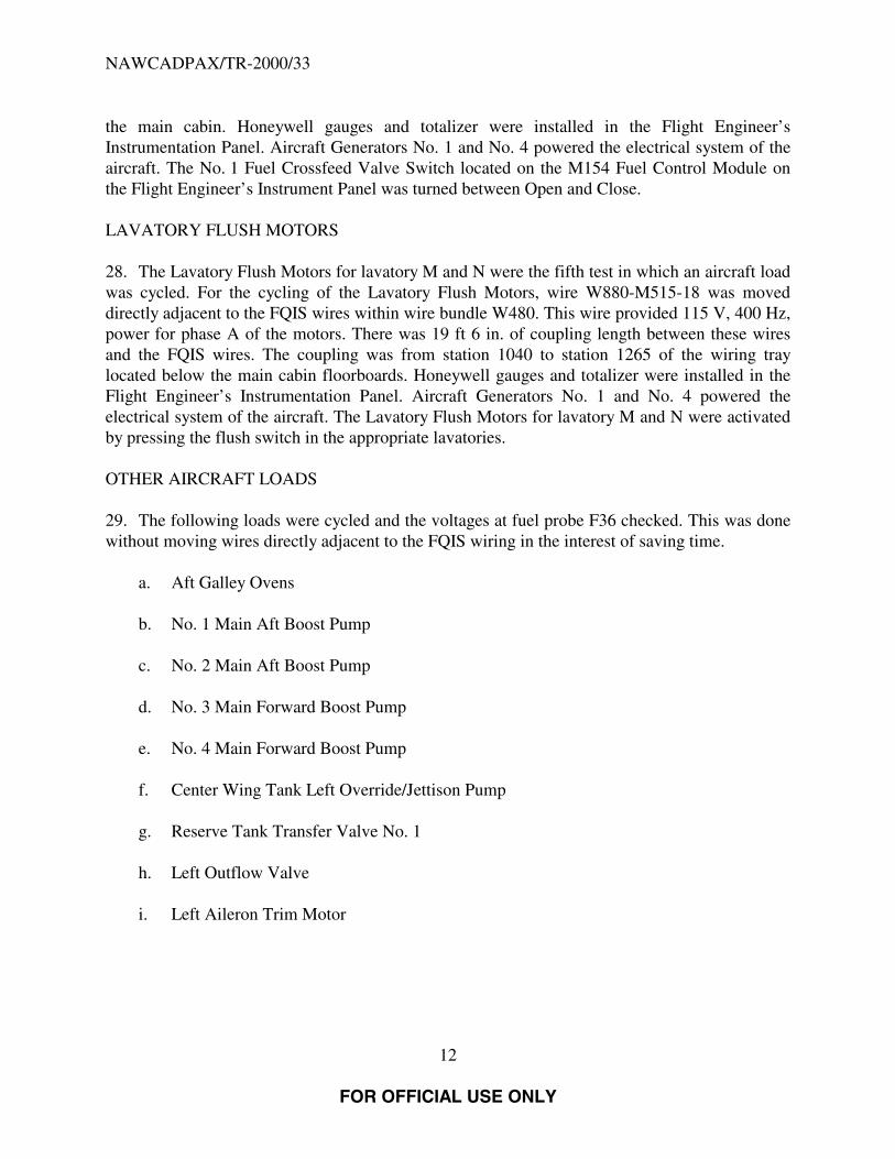
25. The Engine No. 1 Hydraulic Valve test was the second test in which an aircraft load wascycled and produced the highest energy. For the cycling of the Engine No. 1 Hydraulic Valvetest, Wire W528-1M270-18 was moved directly adjacent to the FQIS wires within wire bundleW480. Wire W528-1M270-18 powers the hydraulic depressurization valve of Engine No. 1,which is powered by 28 VDC. There was 39 ft 10 in. of coupling length between wire W528-1M270 and the FQIS wires. The coupling was from station 400 at the sidewall of the upper deckto station 920 in the ceiling of the main cabin. Honeywell gauges and totalizer were installed inthe Flight Engineer’s Instrumentation Panel. Aircraft Generators No. 1 and No. 4 powered theelectrical system of the aircraft. The Engine Driven Pump Control Switch, located on the M171System No. 1 Hydraulic Control Module in the Flight Engineer’s Instrumentation Panel wastoggled between Normal and Depressurize/Off.
AUXILIARY POWER UNIT FUEL BOOST PUMP AND AUXILIARY POWER UNIT FUELSHUTOFF VALVE
26. The APU Boost Pump was the third test in which an aircraft load was cycled. For thecycling of the APU Boost Pump test, wires W644-Q686-18, W644-Q99-18, W644-Q100-18, andW644-W75-20 were moved directly adjacent to the FQIS wires within wire bundle W480. Thefirst wire provided 28 VDC power to the APU Fuel Boost Pump. The next two wires provided 28VDC power for closing and opening of the APU Fuel Shutoff Valve, respectively. The last wireprovided APU Fuel Pump pressure indication. There was 19 ft 0 in. of coupling length betweenthese wires and the FQIS wires. The coupling was from station 1040 to station 1265 of the wiringtray located below the main cabin floorboards. Honeywell gauges and totalizer were installed inthe Flight Engineer’s Instrumentation Panel. Aircraft Generators No. 1 and No. 4 powered theelectrical system of the aircraft. The APU Master Control Switch, located on the M176 APUControl Module in the Flight Engineer’s Instrumentation Panel was toggled between On/Startand Off.
NO. 1 FUEL CROSSFEED VALVE
27. The No. 1 Fuel Crossfeed Valve was the fourth test in which an aircraft load was cycled. Forthe cycling of the No. 1 Fuel Crossfeed Valve test, wires W292-1Q28-18 and W292-1Q28-18were moved directly adjacent to the FQIS wires within wire bundle W480. These two wiresprovided 28 VDC power for opening and closing of the No. 1 Fuel Crossfeed Valve,respectively. There was 52 ft 10 in. of coupling length between these wires and the FQIS wires.The coupling was from station 400 at the ceiling of the flight deck to station 920 in the ceiling of
NAWCADPAX/TR-2000/33
12
FOR OFFICIAL USE ONLY
the main cabin. Honeywell gauges and totalizer were installed in the Flight Engineer’sInstrumentation Panel. Aircraft Generators No. 1 and No. 4 powered the electrical system of theaircraft. The No. 1 Fuel Crossfeed Valve Switch located on the M154 Fuel Control Module onthe Flight Engineer’s Instrument Panel was turned between Open and Close.
LAVATORY FLUSH MOTORS
28. The Lavatory Flush Motors for lavatory M and N were the fifth test in which an aircraft loadwas cycled. For the cycling of the Lavatory Flush Motors, wire W880-M515-18 was moveddirectly adjacent to the FQIS wires within wire bundle W480. This wire provided 115 V, 400 Hz,power for phase A of the motors. There was 19 ft 6 in. of coupling length between these wiresand the FQIS wires. The coupling was from station 1040 to station 1265 of the wiring traylocated below the main cabin floorboards. Honeywell gauges and totalizer were installed in theFlight Engineer’s Instrumentation Panel. Aircraft Generators No. 1 and No. 4 powered theelectrical system of the aircraft. The Lavatory Flush Motors for lavatory M and N were activatedby pressing the flush switch in the appropriate lavatories.
OTHER AIRCRAFT LOADS
29. The following loads were cycled and the voltages at fuel probe F36 checked. This was donewithout moving wires directly adjacent to the FQIS wiring in the interest of saving time.
a. Aft Galley Ovens
b. No. 1 Main Aft Boost Pump
c. No. 2 Main Aft Boost Pump
d. No. 3 Main Forward Boost Pump
e. No. 4 Main Forward Boost Pump
f. Center Wing Tank Left Override/Jettison Pump
g. Reserve Tank Transfer Valve No. 1
h. Left Outflow Valve
i. Left Aileron Trim Motor

NAWCADPAX/TR-2000/33
13
FOR OFFICIAL USE ONLY
CABLE CUTS/CRUSHES
30. There were three cable cuts/crushes performed. Honeywell gauges and totalizer wereinstalled in the Flight Engineer’s Instrumentation Panel. Aircraft Generators No. 1, No. 2, No. 3,and No. 4 powered the electrical system of the aircraft and the simulated wire bundle via a loaddistribution panel connected at BUS No. 1 in the P14 panel of the aircraft. The distribution panelwas added for safety and to have representative aircraft circuit breakers feeding the simulatedaircraft loads. The size of the wires, circuit breaker sizes feeding the load, and the load connectedto the simulated aircraft bundle wires are listed in appendix D. The simulated wire bundle wasplace next to the FQIS wiring from station 1000 to station 1265 of the wiring tray located belowthe main cabin floorboards. There was 19 ft 10 in. of coupling length between the wires of thesimulated wire bundle and the FQIS wires. The simulated wire bundles were run out a window ofthe left wing down to the tarmac. The simulated wire bundle was placed in a cable cutter. AnEPSD electrical power feeder harness protected by EPSD and aircraft circuit breakers wasconnected to aircraft power-generating systems within the aircraft. The EPSD electrical powerfeeder harness was installed along side the FQIS cabling. External load banks provided by theFAA and Boeing were used to energize the EPSD electrical power feeder harness during thesimulated short circuit and wire bundle-crush tests. A portion of the EPSD electrical powerfeeder harness was routed outside the aircraft to an EPSD cable cutter/crusher mechanism locatedon the ground. The EPSD electrical power feeder harness was cut and crushed utilizing sharp anddull blades, respectively. The cable cutter/crusher was activated by a mechanism that dropped aweight onto these cable-cutter blades. The cable cutting/crusher mechanism was electricallygrounded to the aircraft and electrically isolated from the operator.
PARAMETRIC SPACING TESTS
31. For the Parametric Spacing test, a simulated aircraft load was used. The simulated aircraftload was a three phase network of inductors connected in wye of 3.12 milliHenries per phase andfeed via six cables, three 12 AWG and three 14 AWG. The simulated aircraft load was cycled bya relay provided by Boeing P/N 58657-9126. For this test, the load was cycled with the loadwires directly adjacent to the FQIS wires within wire bundle W480 and with the load wiresspaced at set distances of ¼ in., ½ in., 1 in., 2 in., and 4 in. from the FQIS wiring. There was 19 ft8 in. of coupling length between these wires and the FQIS wires. The coupling is from station1000 to station 1240 of the wiring tray located below the main cabin floorboards. Honeywellgauges and totalizer were installed in the Flight Engineer’s Instrumentation Panel. AircraftGenerators No. 1 and No. 4 powered the electrical system of the aircraft. The simulated aircraftload was powered from the AC Bus No. 1 via the installed relay.
COCKPIT VOICE RECORDER VOLTAGE HARMONICS
32. Voltage harmonic spectrum measurements were taken at the input to the Captain’s channelof the CVR for various electrical load conditions. The input pins to the Captain’s channel wereconfirmed by keying the Captain’s microphone and confirming the change in voltage at the pins.Generators No. 1, No. 2, No. 3, and No. 4 powered the electrical systems of the aircraft. The

NAWCADPAX/TR-2000/33
14
FOR OFFICIAL USE ONLY
electrical load conditions of the aircraft were varied and harmonic spectrum recorded. Theelectrical load conditions are as follows:
a. Base Load Case
b. Storm Lights On
c. Overhead Panel Lights Off
d. Instrument Lights Captain-side Off
e. Upper Deck Light Breaker Pulled
f. Upper Deck Galley Equipment On
g. Keying the Passenger Address Microphone
h. Passenger Address Pressed on Captain’s Audio
i. Open Split System Breaker
j. Open GCB 3 and GCB 4
k. All GCB’s Open, No Emergency Lights
l. All GCB’s Closed, No Emergency Lights (Spectrum taken immediately after closingGCB’s)
m. All GCB’s Open, with Emergency Lights
n. All GCB’s Closed (Spectrum taken immediately after closing GCB’s)
o. GCB 1 and GCB 2 Open
p. Breaker Pulled for transformer rectifier unit (TRU) 1
q. Breaker Pulled for TRU2
r. Breaker Pulled for TRU3
s. Essential Power Selector to BUS 3
t. Essential Power Selector to BUS 2

NAWCADPAX/TR-2000/33
15
FOR OFFICIAL USE ONLY
u. Essential Power Selector to BUS 1
v. All TRU Breakers Pulled

NAWCADPAX/TR-2000/33
16
FOR OFFICIAL USE ONLY
RESULTS AND EVALUATION
GENERAL
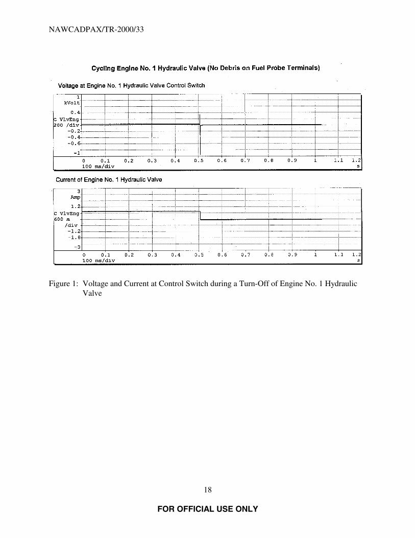
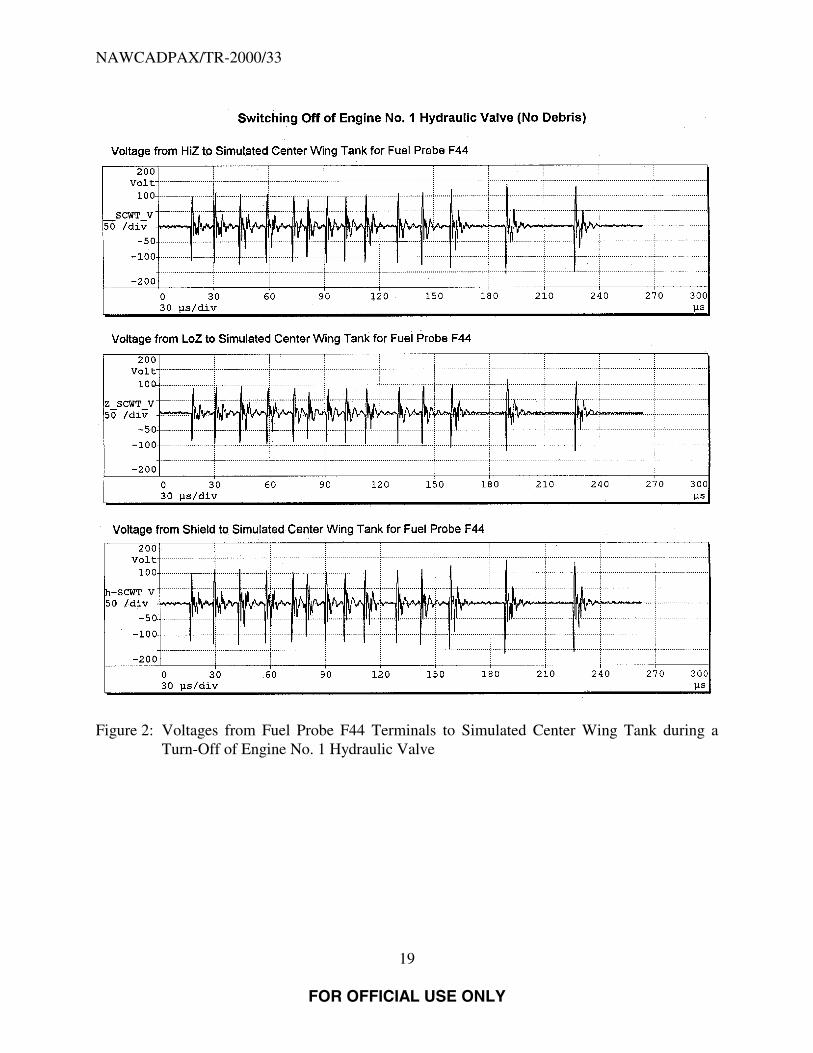
33. The maximum energy calculated for a transient through debris was 125 µJ. The debris was afew strands of aluminum wool placed between the HiZ terminal and the shield terminal of fuelprobe F44 during a turn off of the Engine No. 1 Hydraulic Valve. The transient lasted a durationof 207 µsec. The maximum voltage transient recorded for the no debris condition was 175 Vpeak measured on fuel probe F40 between the Shield terminal of the fuel probe and the simulatedcenter wing tank during a turn off of the Engine No. 1 Hydraulic Valve.
34. The Total Harmonic Distortion (THD) of the base load conditions of the voltages measuredat the CVR Captain’s channel input were approximately 33%. The electrical load conditions thatresulted in a reduction in the THD voltages measured at the CVR Captain’s channel were,immediately after closing all GCB’s, Breaker Pulled for TRU2, Essential Power Selector toBUS 3, Essential Power Selector to BUS 2, Essential Power Selector to BUS 1, and all TRUBreakers Pulled.
ENGINE NO. 1 HYDRAULIC VALVE
35. The results of cycling the Engine No. 1 Hydraulic Valve test are shown in tables E-1 throughE-4. Table 1 summarizes the maximum peak voltages for the no debris conditions. Themaximum voltage transient recorded for the no debris condition was 175 V peak measured onfuel probe F40 between the Shield terminal of the fuel probe and the simulated center wing tank.Figure 1 shows the waveform for the voltage at the switch and the current waveforms for theEngine No. 1 Hydraulic Valve during a turn-off. Figure 2 shows the voltage for the terminal tosimulated center wing tank at fuel probe F44 for a turn-off of the Engine No. 1 Hydraulic Valve.Table 2 summarizes the maximum energies calculated for the debris conditions. The maximumenergy calculated for a transient through debris was 125 µJ and lasted a duration of 207 µsec. Thedebris was a few strands of aluminum wool placed between the HiZ terminal and the shieldterminal of fuel probe F44. This was the maximum energy calculated for any debris condition forthis investigation. Figure 3 shows the waveform for the voltage at the switch and the currentwaveforms for the Engine No. 1 Hydraulic Valve during the turn-off for this debris transient.Figure 4 shows the voltage waveform from HiZ terminal to Shield off fuel probe F44, the currentwaveform for the current passing through the debris, the voltage and current waveforms for theEngine No. 1 Hydraulic Valve during the turn-off for this debris transient.

NAWCADPAX/TR-2000/33
17
FOR OFFICIAL USE ONLY
Table 1: Engine No. 1 Hydraulic Valve Maximum Peak Voltages on Fuel Probes for No Debris Conditions
FuelProbes
HiZ Terminal of FuelProbe to SCWT(1)
(V Peak)
LoZ Terminal of FuelProbe to SCWT
(V Peak)
Shield Terminal ofFuel Probe to SCWT
(V Peak)
HiZ Terminal toShield Terminal of
Fuel Probe(V Peak)
LoZ Terminal toShield Terminal of
Fuel Probe(V Peak)
HiZ Terminal to LoZTerminal of Fuel Probe
(V Peak)F 36 157 137 170 10 27 31F 40 164 124 175 12 79 76F 42 154 143 157 11 40 44F 44 158 130 163 13 69 69
NOTE: (1) SCWT - Simulated Center Wing Tank.
Table 2: Maximum Energy and Duration Calculated for the Debris Conditions of Aluminum Wool Placed between Terminaland Probe as Debris
FuelProbes
Aluminum WoolDebris from HiZTerminal of FuelProbe to SCWT(1)
Aluminum WoolDebris from LoZTerminal of FuelProbe to SCWT
Aluminum WoolDebris from ShieldTerminal of FuelProbe to SCWT
Aluminum WoolDebris from
HiZ Terminal toShield Terminal of
Fuel Probe
Aluminum WoolDebris from
LoZ Terminal toShield Terminal of
Fuel Probe
Aluminum WoolDebris from
HiZ Terminal to LoZTerminal of Fuel
ProbeF 36 87 µJ / 446 µsec 71 µJ / 250 µsec 23 µJ / 187 µsec 28 µJ /189 µsec N/A 98 µJ /221 µsecF 40 36 µJ /249 µsec 51 µJ /200 µsec 19 µJ / 199 µsec 16 µJ / 182 µsec 28 µ / 256 µsec 26 µJ / 181 µsecF 42 17 µJ / 106 µsec 11 µJ / 18 µsec 25 µJ / 166 µsec 28 µJ / 227 µsec 24 µJ / 180 µsec 7 µJ / 27 µsecF 44 74 µJ / 171 µsec 78 µJ / 214 µsec 24 µJ / 198 µsec 125 µJ / 207 µsec N/A 23 µJ / 182 µsec
NOTE: (1) SCWT - Simulated Center Wing Tank.
NAWCADPAX/TR-2000/33
FOR OFFICIAL USE ONLY
18
Figure 1: Voltage and Current at Control Switch during a Turn-Off of Engine No. 1 HydraulicValve
NAWCADPAX/TR-2000/33
FOR OFFICIAL USE ONLY
19
Figure 2: Voltages from Fuel Probe F44 Terminals to Simulated Center Wing Tank during aTurn-Off of Engine No. 1 Hydraulic Valve
NAWCADPAX/TR-2000/33
FOR OFFICIAL USE ONLY
20
Figure 3: Voltage and Current at Control Switch during Turn-Off of Engine No. 1 HydraulicValve with Debris from HiZ Terminal to Shield of Fuel Probe 44

NAWCADPAX/TR-2000/33
FOR OFFICIAL USE ONLY
21
Figure 4: Voltage from HiZ Terminal to Shield of Fuel Probe F44, Current through DebrisPlaced between HiZ Terminal and Shield of Fuel Probe F44, Voltage at ControlSwitch of Engine No. 1 Hydraulic Valve, and Current of Engine No. 1 HydraulicValve during Turn-Off of Engine No. 1 Hydraulic Valve

NAWCADPAX/TR-2000/33
FOR OFFICIAL USE ONLY
22
AUXILIARY POWER UNIT FUEL BOOST PUMP AND AUXILIARY POWER UNIT FUELSHUTOFF VALVE
36. The results of cycling the APU Boost Pump test are shown in tables E-5 and E-6. Themaximum voltage transient recorded for the no debris condition was 68 V peak measured on fuelprobe F44 between the LoZ terminal of the fuel probe and the simulated wing tank. Themaximum energy calculated for a transient through debris was 73 µJ and lasted a duration of390 µsec. The debris was a few strands of aluminum wool placed between the HiZ terminal andthe Shield terminal of fuel probe F44.
NO. 1 FUEL CROSSFEED VALVE
37. The results of cycling No. 1 Fuel Crossfeed Valve test are shown in table E-7. Themaximum voltage transient recorded for the no debris condition was 142 V peak measured onfuel probe F44 between the Shield terminal of the fuel probe and the simulated wing tank. Themaximum energy calculated for a transient through debris was 21 µJ and lasted a duration of29 µsec. The debris was a few strands of aluminum wool placed between the HiZ terminal of fuelprobe F44 and the simulated center wing tank.
SCAVENGE PUMP
38. The results of cycling the Scavenge Pump test are shown in tables E-8 and E-9. Themaximum voltage transient recorded for the no debris conditions was 88 V peak measured onfuel probe F44 between the Shield terminal of the fuel probe and the simulated wing tank. Nosignificant differences were noted in the transients produced by either Smiths gauges andtotalizer or Honeywell gauges and totalizer. The maximum energy for transients through debriscould not be calculated due to the high background noise of the current measurement.Instrumentation was changed subsequent to the Scavenge Pump test to eliminate these problems.The longest transient for the Scavenge Pump test lasted 563 µsec.
BUS TRANSFERS
39. The results of the Bus Transfer are shown in table E-10. The maximum voltage transientrecorded for the no debris condition was 18 V peak measured on fuel probe F36 between the LoZterminal of the fuel probe and the simulated wing tank. The maximum energy for transientsthrough debris could not be calculated due to the high background noise of the currentmeasurement. Instrumentation was changed subsequent to the Scavenge Pump test to eliminatethese problems. The longest transient for the Bus Transfer tests lasted 1,040 µsec.
LAVATORY FLUSH MOTORS
39. The results of cycling the Lavatory Flush Motors for lavatory M and N test are shown intable E-11. The maximum voltage transient recorded for the no debris condition was 10 V peak
NAWCADPAX/TR-2000/33
FOR OFFICIAL USE ONLY
23
measured on fuel probe F36 between the Shield terminal of the fuel probe and the simulatedcenter wing tank. The debris conditions and thus the energy calculation were not performedbecause of the low voltage levels in the no debris tests. The longest transient for the LavatoryFlush Motors test lasted 114 µsec.
OTHER AIRCRAFT LOADS
41. None of the aircraft loads listed below resulted in voltage transient large enough to triggerevent markers on the digital oscilloscope.
a. Aft Galley Ovens
b. No. 1 Main Aft Boost Pump
c. No. 2 Main Aft Boost Pump
d. No. 3 Main Forward Boost Pump
e. No. 4 Main Forward Boost Pump
f. Center Wing Tank Left Override/Jettison Pump
g. Reserve Tank Transfer Valve No. 1
h. Left Outflow Valve
i. Left Aileron Trim Motor
CABLE CUTS/CRUSHES
42. The maximum current for the cable cuts/crush tests was 660 amps on phase B of the bundlefor the second cut/crush test. The maximum voltage transient recorded was 33 V peak measuredon fuel probe F44 between the LoZ terminal of the fuel probe and the simulated wing tank.
PARAMETRIC SPACING TESTS
43. The maximum peak voltage transients recorded for the Parametric Spacing test on fuel probeF44 for the various spacing between the load wire and the FQIS wiring are listed below. All themaximum voltages for the fuel probe occurred from the HiZ terminal to the simulated centerwing tank.
a. 0 in. 124 V peak

NAWCADPAX/TR-2000/33
FOR OFFICIAL USE ONLY
24
b. 1/4 in. 71 V peak
c. 1/2 in. 73 V peak
d. 1 in. 52 V peak
e. 2 in. 48 V peak
f. 4 in. 46 V peak
COCKPIT VOICE RECORDER VOLTAGE HARMONICS
44. The results of CVR Voltage Harmonic Spectrum measurements taken at the input to theCaptain’s channel are listed in table F-1. The spectrum plots are shown in figures F-1 throughF-85. The THD of the base load condition of the voltages measured at the CVR Captain’schannel input were 33.13% and 33.78%. The electrical load conditions that resulted in areduction in the THD voltages measured at the CVR Captain’s channel input are listed below.
a. All GCB’s Closed, No Emergency Lights (Spectrum taken immediately after closingGCB’s), THD 12.25%
b. All GCB’s Closed (Spectrum taken immediately after closing breakers), THD 12.09%
c. Breaker Pulled for TRU2, THD 12.30% and THD 12.09%
d. Essential Power Selector to BUS 3, THD 11.98%
e. Essential Power Selector to BUS 2, THD 12.48%
f. Essential Power Selector to BUS 1, THD 12.51%
g. All TRU Breakers Pulled, THD 18.72% and THD 18.86%

NAWCADPAX/TR-2000/33
FOR OFFICIAL USE ONLY
25
THIS PAGE INTENTIONALLY LEFT BLANK
NAWCADPAX/TR-2000/33
FOR OFFICIAL USE ONLY
26
REFERENCES
1. Typical Flammability and Ignition Properties of Aircraft Fuels, Aviation Fuel PropertiesHandbook, of 1983.
2. Boeing 747 Maintenance Manual for Trans World Airlines, Inc., Boeing Doc No. DG-30002, of 25 Apr 1993.
3. Boeing Aircraft Company Letter No: B-B600-16330-ASI, “FQIS EMC Transient Test,TWA 747-100, N93119 Accident off Long Island, New York – 17 July 1996”, of 19 Jan1998.

NAWCADPAX/TR-2000/33
FOR OFFICIAL USE ONLY
27
THIS PAGE INTENTIONALLY LEFT BLANK

NAWCADPAX/TR-2000/33
FOR OFFICIAL USE ONLY
28
GLOSSARY
A ampereAC alternating currentADB Aircraft Discrepancy BookAmp-hr amp-hourAPU auxiliary power unitAWG american wire gaugeBTB bus transfer breakerCVR cockpit voice recorderCWT center wing tankDC direct currentdB decibelEPSD Electrical Power Systems DivisionFAA Federal Aviation AdministrationFQIS Fuel Quantity Indication Systemft feetGCB generator circuit breakerHF high frequencyHz hertz (cycles per second)in. inch(es)kHz kilohertzkS/s kilo-Samples per secondkV kilovoltkVA kilovolt AmpMHz megahertzµJ micro-Joulesµsec microsecondsMΩ megaohmsMs millisecondMS/s Mega-Samples per secondNAWCAD Naval Air Warfare Center Aircraft DivisionNTSB National Transportation Safety BoardSCWT simulated center wing tankSH shieldSSB split system breakerTHD total harmonic distortionTRU transformer rectifier unitTWA Trans World Airlines, Inc.V volt(s)VA volt ampereVAC volts alternating currentVDC volts direct current

NAWCADPAX/TR-2000/33
FOR OFFICIAL USE ONLY
29
VHF very high frequency

NAWCADPAX/TR-2000/33
FOR OFFICIAL USE ONLY
30
THIS PAGE INTENTIONALLY LEFT BLANK

NAWCADPAX/TR-2000/33
31 APPENDIX A
FOR OFFICIAL USE ONLY
APPENDIX AFUEL QUANTITY INDICATION SYSTEM WIRING

NAWCADPAX/TR-2000/33
32 APPENDIX A
FOR OFFICIAL USE ONLY
Figure A-1: FQIS Wiring Locations

NAWCADPAX/TR-2000/33
33 APPENDIX A
FOR OFFICIAL USE ONLY
Figure A-2: Center Wing Tank Fuel Probe Connections and Terminals

NAWCADPAX/TR-2000/33
34
FOR OFFICIAL USE ONLY
THIS PAGE INTENTIONALLY LEFT BLANK

NAWCADPAX/TR-2000/33
35 APPENDIX B
FOR OFFICIAL USE ONLY
APPENDIX BEQUIPMENT AND PERSONNEL TEST LOCATIONS

NAWCADPAX/TR-2000/33
36
FOR OFFICIAL USE ONLY
THIS PAGE INTENTIONALLY LEFT BLANK
NAWCADPAX/TR-2000/33
37 APPENDIXC
FOR OFFICIAL USE ONLY
APPENDIX CFUEL TANK INERTING PROCEDURE
PROCEDURE OVERVIEW
The fuel tank inerting procedure is designed to render all of the test aircraft’s fuel tanks inert tolower the potential for explosions. The procedure will use the pressure refueling lines to deliverthe gaseous nitrogen to each fuel tank.
A standard refueling nozzle has been adapted to accept a pressurized nitrogen line. The refuelingnozzle will be connected to the refueling receptacle in the aircraft, and the nitrogen will flowthrough the refueling lines in the tanks in the same fashion as fuel does during normal refueling.The gaseous nitrogen will be delivered at a pressure of approximately 1.5 psig.
Manual override of the refueling valves will be used in the system to allow for refueling aspecific tank while excluding the others. These valves will be used to direct nitrogen to each tankindividually during the initial inerting, and also to direct nitrogen to all of the tanks during thetests. As the nitrogen is delivered to the fuel tanks, the fuel/air vapors will be driven out of thetanks through the aircraft’s vent system. The vent lines for each tank run to a surge tank wherethey combine to exit the aircraft through a single line. The output for this line is on the undersideof the wing, near the wingtip. There is a vent system output port at each wingtip. The flowcoming out of this vent system output port will be monitored for oxygen content, and the tankswill be considered to be inert once the oxygen concentration drops below 9% (it is desired tolower the oxygen level to 5%). In addition, the total volume of nitrogen put into the tank will bemeasured, and it is expected that 1 to 1.5 complete, empty tank volumes of nitrogen will berequired for each tank to reach the 5% oxygen concentration level.
The tanks will be continuously inerted during the tests by a continuous flow of nitrogen into thetanks. The continuous flow will be metered to provide the volume necessary to make up for thefuel burned while the engines are running. A minimum flow calibration procedure will beperformed to calibrate each refueling valve’s minimum flow condition. A member of the testteam will be designated the “inerting system monitor” and will be tasked with monitoring theoxygen concentration in the vent system output ports prior to each test.
GENERAL SYSTEM DESCRIPTION: PRESSURE FUELING SYSTEM
(Note: This is the general system description of the pressure fueling system. It discusses aspectsof the system as they relate to normal pressure fueling. In most cases, changing the context fromJet-A refueling to nitrogen inerting will lead to the proper system description.)
NAWCADPAX/TR-2000/33
38 APPENDIXC
FOR OFFICIAL USE ONLY
The pressure fueling system provides a rapid means of filling the fuel tanks in the airplane. Thesystem distributes fuel under pressure from a fueling station in each wing to the tanks throughmanifolds and refuel valves. The refuel valves allow fuel to flow from the main distributionmanifold into the tanks. Refuel valves are installed as follows: one in each reserve and outboardtank; two in each of the inboard main and the center wing tanks.
The fueling station is equipped with two fueling receptacles coupled together to a manifold thatextends through the outboard main tank to the main distribution manifold. Each receptacleincorporates a manual shutoff valve. The fueling station in the left wing is provided with acontrol panel consisting of fueling quantity (repeater) indicators, refuel valve control switches,valve position indicator lights, a refuel power switch, and a test switch for the volumetric shutoffcontrol unit, and indicators. A proximity switch is actuated by the door to cut off all power to thepanel when the door is closed.
The fueling receptacles provide a means of connecting ground refueling hose nozzles to thepressure fueling system. Two receptacles at each fueling station are mounted on the front sparforward face. Each receptacle consists of a fueling nozzle adapter, a cast aluminum elbow, a cap,a spring-loaded check valve and a manual shutoff valve attached to the spar and connected to themanifold. The fueling nozzle adapter has mating lugs that couple with and secure the fuelinghose.
When the hose nozzle is coupled to the adapter, the spring-loaded check valve is lifted to aposition that allows the hose nozzle to lock in place. During pressure fueling, the check valveopens only when nozzle fuel pressure is greater than receptacle manifold pressure. (Dependingon the cracking pressure for this valve, it may or may not open during inerting operations atrelatively low pressures. If the nitrogen delivery pressure is insufficient to open the check valve,the receptacle may be put in the defuel configuration (lift lever on popet up), and the check valvewill be open as soon as the refuel nozzle is inserted. Care must be taken, however, since thismeans that if the tank fuel level is above the height of the refuel valve, fuel back flow can occur.The fuel levels in the individual tanks must be monitored to make sure that they do not exceedthe level of the refuel valve to prevent back flow.)
The refueling manifold distributes fuel to all tanks during a pressure fueling operation. Themanifold consists of two crossover manifolds and main distribution manifold; the maindistribution manifold is also used as the fuel jettison manifold. The crossover manifolds extendfrom the fueling receptacles at the front spar through outboard main tanks to the maindistribution manifold. The main distribution manifold is routed inside the fuel tank area withsolenoid-controlled refuel valves installed in each tank. Manual override of the valve is providedin the event of valve failure during fueling operation. The refuel valve can be opened or closedmanually by turning the valve override screw up to 10 - 13 complete revolutions in the directionindicated on the override screw retainer (clockwise to close/counterclockwise to open). Note thatfuel pressure should be removed from the fuel manifold during the opening/closing of therefueling valves in manual override.

NAWCADPAX/TR-2000/33
39 APPENDIXC
FOR OFFICIAL USE ONLY
MINIMUM FLOW CALIBRATION TESTS
This test is required to document the minimum number of turns on the manual override of therefueling valves that are required to achieve a minimum flow condition. The minimum flowcondition is important for the continuous inerting phase of the inerting operations. Each refuelingvalve will be opened individually, and flow will be checked to determine if nitrogen will flow.The actual flow rate demonstrated in that condition will be recorded.
The procedure is as follows:
a. Remove fueling receptacle caps.
b. Connect test fueling nozzle to fueling receptacles at left wing station.
c. Open test fueling nozzle manual shutoff valve
d. Open manual shutoff valve at fueling receptacles.
e. Note: All BA airplanes are equipped with a refuel system left to right isolation valve.This valve will need to be opened prior to inerting fuel tanks on the opposite side ofwhichever refuel receptacle is used.
f. Manually open (or increase the opening of the) applicable refuel valve.
(1) Verify fueling manifold has been depressurized.
(2) Remove lockwire from knurled knob of valve override screw (if applicable).Note: Do not remove retainer plate lockwire, screws, or retainer plate.
(3) Turn override screw (knurled knob) 1 (or one additional, as applicable) completerevolution in counterclockwise direction. Note: Pliers may be required to initiallyloosen override screw and to overcome increasing poppet spring pressure.
g. Start flow of nitrogen.
h. Note: Nitrogen will also flow through the manifold drain lines into the inboard maintanks
i. Monitor nitrogen supply flow meter. If nitrogen is flowing, test is complete for thatvalve. Record flow rate. If nitrogen is not flowing, turn off nitrogen supply and return tostep f.
j. Stop flow of nitrogen.
NAWCADPAX/TR-2000/33
40 APPENDIXC
FOR OFFICIAL USE ONLY
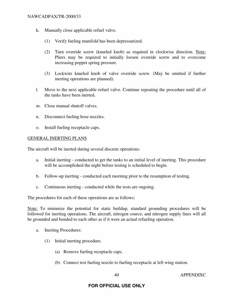
k. Manually close applicable refuel valve.
(1) Verify fueling manifold has been depressurized.
(2) Turn override screw (knurled knob) as required in clockwise direction. Note:Pliers may be required to initially loosen override screw and to overcomeincreasing poppet spring pressure.
(3) Lockwire knurled knob of valve override screw. (May be omitted if furtherinerting operations are planned).
l. Move to the next applicable refuel valve. Continue repeating the procedure until all ofthe tanks have been inerted.
m. Close manual shutoff valves.
n. Disconnect fueling hose nozzles.
o. Install fueling receptacle caps.
GENERAL INERTING PLANS
The aircraft will be inerted during several discrete operations:
a. Initial inerting - conducted to get the tanks to an initial level of inerting. This procedurewill be accomplished the night before testing is scheduled to begin.
b. Follow-up inerting - conducted each morning prior to the resumption of testing.
c. Continuous inerting - conducted while the tests are ongoing.
The procedures for each of these operations are as follows:
Note: To minimize the potential for static buildup, standard grounding procedures will befollowed for inerting operations. The aircraft, nitrogen source, and nitrogen supply lines will allbe grounded and bonded to each other as if it were an actual refueling operation.
a. Inerting Procedures:
(1) Initial inerting procedure.
(a) Remove fueling receptacle caps.
(b) Connect test fueling nozzle to fueling receptacle at left wing station.

NAWCADPAX/TR-2000/33
41 APPENDIXC
FOR OFFICIAL USE ONLY
(c) Open test fueling nozzle manual shutoff valve.
(d) Open manual shutoff valves at fueling receptacles.
(e) Note: All BA airplanes are equipped with a refuel system left to rightisolation valve. This valve will need to be opened prior to inerting fuel tankson the opposite side of whichever refuel receptacle is used.
(f) Manually open applicable refuel valve.
1. Verify fueling manifold has been depressurized.
2. Remove lockwire from knurled knob of valve override screw. Note: Donot remove retainer plate lockwire, screws, or retainer plate.
3. Turn override screw (knurled knob) 10-13 complete revolutions incounterclockwise direction. Note: Pliers may be required to initiallyloosen override screw and to overcome increasing poppet spring pressure.
(g) Start flow of nitrogen.
(h) Monitor oxygen concentration of vent outflow ports.
(i) When oxygen concentration falls below 9%, continue flow for an additional10 min or until the oxygen concentration falls below 5%. Note that theamount of nitrogen introduced into the tank should equal 1-1.5 times theempty volume of the tank. (Note: Some of this nitrogen flow will be going tothe inboard main tanks through the refuel manifold drain lines.
(j) Stop flow of nitrogen.
(k) Manually close applicable refuel valve.
1. Verify fueling manifold has been depressurized.
2. Turn override screw (knurled knob) 10-13 complete revolutions inclockwise direction. Note: Pliers may be required to initially loosenoverride screw and to overcome increasing poppet spring pressure.
3. Lockwire knurled knob of valve override screw. (May be omitted iffurther inerting operations are planned).

NAWCADPAX/TR-2000/33
42 APPENDIXC
FOR OFFICIAL USE ONLY
(l) Note: All BA airplanes are equipped with a refuel system left to rightisolation valve. This valve will need to be opened prior to inerting fuel tankson the opposite side of whichever refuel receptacle is used.
(m) Move to the next applicable refuel valve. Continue repeating the procedureuntil all of the tanks have been inerted.
(n) Close manual shutoff valves.
(o) Disconnect fueling hose nozzles.
(p) Install fueling receptacle caps.
b. Follow-up Inerting Procedures:
(1) Remove fueling receptacle caps.
(2) Connect test fueling nozzles to fueling receptacle at left wing station.
(3) Open test fueling nozzle manual shutoff valve.
(4) Open manual shutoff valves at fueling receptacles.
(5) Note: All BA airplanes are equipped with a refuel system left to right isolationvalve. This valve will need to be opened prior to inerting fuel tanks on theopposite side of whichever refuel receptacle is used.
(6) Manually open applicable refuel valve.
(a) Verify fueling manifold has been depressurized.
(b) Remove lockwire from knurled knob of valve override screw (if applicable).Note: Do not remove retainer plate lockwire, screws, or retainer plate.
(c) Turn override screw (knurled knob) 10-13 complete revolutions incounterclockwise direction. Note: Pliers may be required to initially loosenoverride screw and to overcome increasing poppet spring pressure.
(7) Start flow of nitrogen.
(8) Monitor oxygen concentration of vent outflow ports.
(9) Continue flow of nitrogen until oxygen concentration falls below 5% desired, 9%required.
NAWCADPAX/TR-2000/33
43 APPENDIXC
FOR OFFICIAL USE ONLY
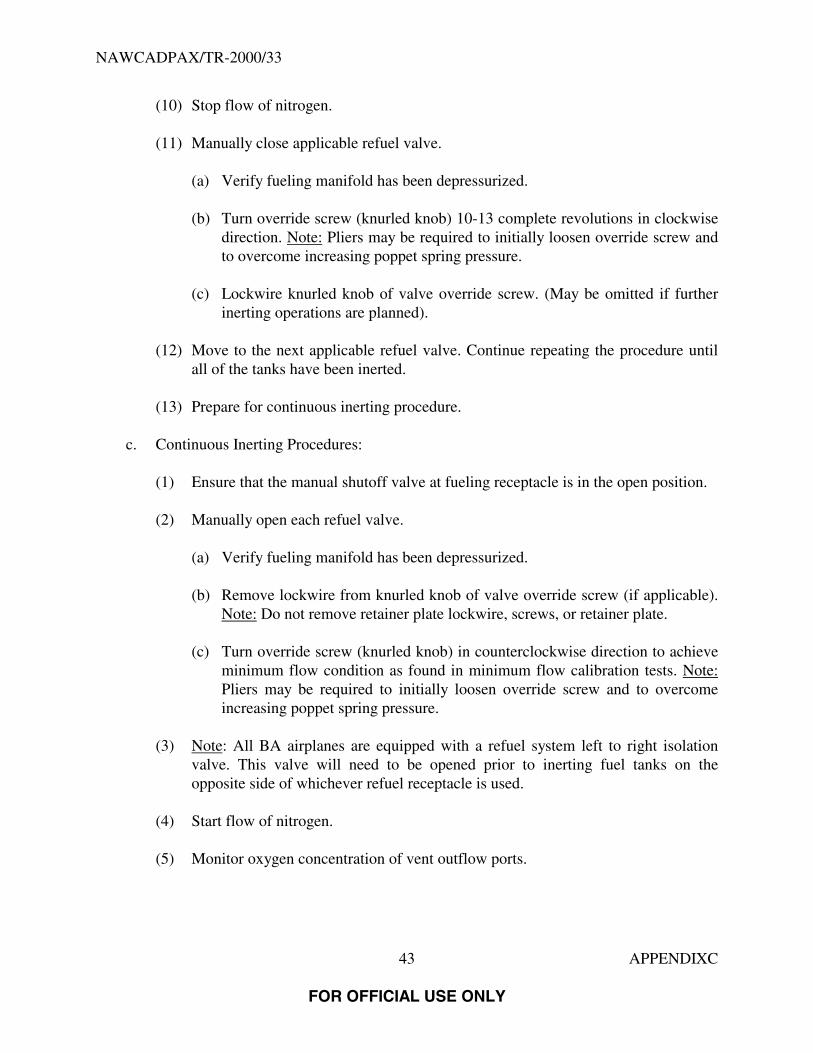
(10) Stop flow of nitrogen.
(11) Manually close applicable refuel valve.
(a) Verify fueling manifold has been depressurized.
(b) Turn override screw (knurled knob) 10-13 complete revolutions in clockwisedirection. Note: Pliers may be required to initially loosen override screw andto overcome increasing poppet spring pressure.
(c) Lockwire knurled knob of valve override screw. (May be omitted if furtherinerting operations are planned).
(12) Move to the next applicable refuel valve. Continue repeating the procedure untilall of the tanks have been inerted.
(13) Prepare for continuous inerting procedure.
c. Continuous Inerting Procedures:
(1) Ensure that the manual shutoff valve at fueling receptacle is in the open position.
(2) Manually open each refuel valve.
(a) Verify fueling manifold has been depressurized.
(b) Remove lockwire from knurled knob of valve override screw (if applicable).Note: Do not remove retainer plate lockwire, screws, or retainer plate.
(c) Turn override screw (knurled knob) in counterclockwise direction to achieveminimum flow condition as found in minimum flow calibration tests. Note:Pliers may be required to initially loosen override screw and to overcomeincreasing poppet spring pressure.
(3) Note: All BA airplanes are equipped with a refuel system left to right isolationvalve. This valve will need to be opened prior to inerting fuel tanks on theopposite side of whichever refuel receptacle is used.
(4) Start flow of nitrogen.
(5) Monitor oxygen concentration of vent outflow ports.

NAWCADPAX/TR-2000/33
44 APPENDIXC
FOR OFFICIAL USE ONLY
(6) Ensure that oxygen concentration stays below 9%. If oxygen concentrationincreases above 9%, stop tests. Since the oxygen monitors are only registering theoxygen concentration in the combined vent system output, all of the tanks must berechecked to ensure total inerting of the aircraft. Repeat follow-on inertingprocedure until the oxygen concentration in all tanks has been lowered below 9%.As a precaution, when oxygen concentration reaches 7%, increase the flow ofnitrogen by increasing the supply pressure.
(7) Once testing is complete, stop flow of nitrogen.
(8) Manually close applicable refuel valves.
(a) Verify fueling manifold has been depressurized.
(b) Turn override screw (knurled knob) as required in clockwise direction. Note:Pliers may be required to initially loosen override screw and to overcomeincreasing poppet spring pressure.
(c) Lockwire knurled knob of valve override screw. (May be omitted if furtherinerting operations are planned).
(9) Close manual shutoff valves.
(10) Disconnect fueling hose nozzle.
(11) Install fueling receptacle caps.

NAWCADPAX/TR-2000/33
45 APPENDIXC
FOR OFFICIAL USE ONLY
LEFT WING FUEL PRESSURE FILLING SYSTEM DIAGRAM

NAWCADPAX/TR-2000/33
46
FOR OFFICIAL USE ONLY
THIS PAGE INTENTIONALLY LEFT BLANK

NAWCADPAX/TR-2000/33
47 APPENDIX D
FOR OFFICIAL USE ONLY
APPENDIX DLOADS FOR CABLE CUT/CRUSH TESTS
Wire No. Wire Size Circuit Breaker Rating Power Phase Load Current Low Impedance Ohms Resistance/Reactance Watts or VA1 12 A 8.65 A 13.3 Ohms 5.29 mH 995 VA2 12 3-phase 20 amp 3-phase 115 VAC B 8.65 A 13.3 Ohms 5.29 mH 995 VA3 12 C 8.65 A 13.3 Ohms 5.29 mH 995 VA4 14 A 6.00 A 19.2 Ohms 7.63 mH 690 VA5 14 3-phase 10 amp 3-phase 115 VAC B 6.00 A 19.2 Ohms 7.63 mH 690 VA6 14 C 6.00 A 19.2 Ohms 7.63 mH 690 VA7 16 A 4.50 A 25.6 Ohms 10.17 mH 518 VA8 16 3-phase 7.5 amp 3-phase 115 VAC B 4.50 A 25.6 Ohms 10.17 mH 518 VA9 16 C 4.50 A 25.6 Ohms 10.17 mH 518 VA
10 16 7.5 amp Single 115 VAC A 2.95 A 39.0 Ohms 39.0 Ohms 339 W11 16 7.5 amp 28 VDC + 2.80 A 10.0 Ohms 10.0 Ohms 322 W12 16 7.5 amp 28 VDC + Unk Relay Relay Unknown13 18 A 3.00 A 38.3 Ohms 15.25 mH 345 VA14 18 3-phase 7.5 amp 3-phase 115 VAC B 3.00 A 38.3 Ohms 15.25 mH 345 VA15 18 C 3.00 A 38.3 Ohms 15.25 mH 345 VA16 18 A 2.00 A 57.5 Ohms 22.88 mH 230 VA17 18 3-phase 5 amp 3-phase 115 VAC B 2.00 A 57.5 Ohms 22.88 mH 230 VA18 18 C 2.00 A 57.5 Ohms 22.88 mH 230 VA19 18 5 amp Single 115 VAC A 2.50 A 46.0 Ohms 18.30 mH 288 VA20 18 5 amp Single 115 VAC B 2.45 A 47.0 Ohms 47.0 Ohms 281 W21 18 5 amp Single 115 VAC C 0.00 A Open Open N/A22 18 5 amp 28 VDC + 2.80 A 10.0 Ohms 10.0 Ohms 322 W23 18 2.5 amp 28 VDC + Unk Relay Relay Unknown24 18 2.5 amp 28 VDC + 0.00 A Open Open N/A25 20 A 2.00 A 57.5 Ohms 22.88 mH 230 VA26 20 3-phase 3 amp 3-phase 115 VAC B 2.00 A 57.5 Ohms 22.88 mH 230 VA27 20 C 2.00 A 57.5 Ohms 22.88 mH 230 VA28 20 2.5 amp Single 115 VAC A 2.00 A 57.5 Ohms 22.88 mH 230 VA29 20 2.5 amp Single 115 VAC B 1.00 A 115.0 Ohms 45.76 mH 115 VA30 20 2.5 amp Single 115 VAC C 0.96 A 120.0 Ohms 120.0 Ohms 110 W31 20 1 amp Single 115 VAC A 0.51 A 225.0 Ohms 225.0 Ohms 59 W32 20 1 amp Single 115 VAC B 0.00 A Open Open N/A33 20 2.5 amp 28 VDC + 0.50 A Relay Relay Unknown34 20 2.5 amp 28 VDC + 0.50 A Relay Relay Unknown35 20 2.5 amp 28 VDC + 0.00 A Open Open N/A36 20 1 amp 28 VDC + 0.00 A Open Open N/A

NAWCADPAX/TR-2000/33
48
FOR OFFICIAL USE ONLY
THIS PAGE INTENTIONALLY LEFT BLANK

NAWCADPAX/TR-2000/33
49 APPENDIX E
FOR OFFICIAL USE ONLY
APPENDIX EENERGY MEASUREMENTS AT FUEL PROBES FOR LOAD SWITCHINGS

NAWCADPAX/TR-2000/33
50 APPENDIX E
FOR OFFICIAL USE ONLY
Table E-1: Engine No. 1 Hydraulic Valves, Load Switching Event 3
Generators 1 and 4 - Honeywell Gauges
Fuel Probe F36No Debris
Debris HiZ-to-SCWT(1)
Debris LoZ-SCWT
Debris Shield-SCWT
Debris HiZ-Shield
Debris LoZ-Shield
Debris HiZ-LoZ
Maximum Peak Voltage at Fuel Probe (V) 170 47 106 37 41 10 31Location of Maximum Peak Voltage Shield-SCWT LoZ-SCWT LoZ-SCWT LoZ-SCWT HiZ-LoZ HiZ-LoZ HiZ-LoZMaximum Peak Current at Debris (mAmp) N/A 1072 1302 1218 498 502 598Maximum Energy Dissipated at Debris (µJ) N/A 87 71 23 N/A 28 98Maximum Duration (µsec) 370 390 267 185 224 192 1,720Minimum Duration (µsec) 147 156 153 185 84 59 105Maximum Peak Voltage across Load Switch (V) 1,050 406 1,189 1,102 1,090 350 1,146Maximum Peak Current of Load (amp) 10 134 161 134 179 76 167
NOTE (1) SCWT - Simulated Center Wing Tank
Table E-2: Engine No. 1 Hydraulic Valve, Load Switching Event 3
Generators 1 and 4 - Honeywell Gauges
Fuel Probe F40No Debris
Debris HiZ-to-SCWT(1)
Debris LoZ-SCWT
Debris Shield-SCWT
Debris HiZ-Shield
Debris LoZ-Shield
Debris HiZ-LoZ
Maximum Peak Voltage at Fuel Probe (V) 175 58 122 54 62 14 11Location of Maximum Peak Voltage Shield-SCWT LoZ-SCWT HiZ-SCWT LoZ-SCWT HiZ-LoZ HiZ-LoZ HiZ-LoZMaximum Peak Current at Debris (mAmp) N/A 992 1328 998 528 882 762Maximum Energy Dissipated at Debris (µJ) N/A 36 51 19 28 25 16Maximum Duration (µsec) 202 248 739 206 163 232 161Minimum Duration (µsec) 111 29 32 108 11 65 13Maximum Peak Voltage across Load Switch (V) 1,196 1,137 1,051 109 1,075 1,078 1,027Maximum Peak Current of Load (amp) 152 163 178 159 165 169 187
NOTE (1) SCWT - Simulated Center Wing Tank

NAWCADPAX/TR-2000/33
51 APPENDIX E
FOR OFFICIAL USE ONLY
Table E-3: Engine No. 1 Hydraulic Valve, Load Switching Event 3
Generators 1 and 4 - Honeywell Gauges
Fuel Probe F42No Debris
Debris HiZ-to-SCWT(1)
Debris LoZ-SCWT
Debris Shield-SCWT
Debris HiZ-Shield
Debris LoZ-Shield
Debris HiZ-LoZ
Maximum Peak Voltage at Fuel Probe (V) 157 42 92 38 49 11 20Location of Maximum Peak Voltage Shield-SCWT LoZ-SCWT - LoZ-SCWT HiZ-LoZ LoZ-shld LoZ-ShieldMaximum Peak Current at Debris (mAmp) N/A 1,035 1,112 1,195 530 1,037 797Maximum Energy Dissipated at Debris (µJ) N/A 17 11 25 28 24 7Maximum Duration (µsec) 220 59 38 28 216 182 27Minimum Duration (µsec) 69 29 29 28 83 119 15Maximum Peak Voltage across Load Switch (V) 1,090 1,036 1,137 1,077 1,037 985 1,112Maximum Peak Current of Load (amp) 200 168 109 157 162 143 171
NOTE (1) SCWT - Simulated Center Wing Tank
Table E-4: Engine No. 1 Hydraulic Valve, Load Switching Event 3
Generators 1 and 4 - Honeywell Gauges
Fuel Probe F44No Debris
Debris HiZ-to-SCWT(1)
Debris LoZ-SCWT
Debris Shield-SCWT
Debris HiZ-Shield
Debris LoZ-Shield
Debris HiZ-LoZ
Maximum Peak Voltage at Fuel Probe (V) 163 197 114 48 69 127 27Location of Maximum Peak Voltage Shield-SCWT Shield-SCWT HiZ-SCWT LoZ-SCWT LoZ-Shield LoZ-Shield LoZ-ShieldMaximum Peak Current at Debris (mAmp) N/A 773 1,300 953 150 1 N/AMaximum Energy Dissipated at Debris (µJ) N/A 197 78 32 7 125 23Maximum Duration (µsec) 596 631 205 219 227 218 225Minimum Duration (µsec) 168 187 155 187 153 167 149Maximum Peak Voltage across Load Switch (V) 1,105 1,179 1,088 1,019 1,046 1,087 1,140Maximum Peak Current of Load (amp) 174 182 164 172 165 177 166
NOTE (1) SCWT - Simulated Center Wing Tank

NAWCADPAX/TR-2000/33
52 APPENDIX E
FOR OFFICIAL USE ONLY
Table E-5: APU Boost Pump - Turn “On”, Load Switching Event 4
Fuel Probe F44
No DebrisDebris HiZ-to-
SCWT(1)Debris LoZ-to-
SCWT
Debris Shield-to-SCWT Debris HiZ-to-
ShieldDebris LoZ-
ShieldDebris HiZ-
LoZ
Maximum Peak Voltage at Fuel Probe (V) 68 42 31 34 42 11 15Location of Maximum Peak Voltage LoZ-SCWT Loz-SCWT Hiz-SCWT Loz-SCWT Hiz-Loz LoZ - Shield HiZ-ShieldMaximum Peak Current at Debris (mAmp) N/A 480 507 507 933 907 987Maximum Energy Dissipated at Debris (µJ) N/A 20 42 19 61 N/A N/AMaximum Duration (µsec) 352 198 385 396 320 N/A N/AMinimum Duration (µsec) 352 198 385 396 320 N/A N/AMaximum Peak Voltage across Load Switch (V) 98 86 71 84 94 98 92Maximum Peak Current of Load (amp) 153 149 153 154 158 170 172
NOTE (1) SCWT - Simulated Center Wing Tank
Table E-6: APU Boost Pump - Turn “Off”, Load Switching Event 4
Generators 1 and 4 - Honeywell Gauges
Fuel Probe F44
No Debris
Debris HiZ-to-SCWT(1)
Debris LoZ-to-SCWT
DebrisShield-to-
SCWT
Debris HiZ-to-Shield Debris HiZ-
Shield
Debris LoZ-Shield Debris HiZ-
LoZ
Maximum Peak Voltage at Fuel Probe (V) 15 14 13 15 15 24 9 14Location of Maximum Peak Voltage LoZ-SCWT Loz-SCWT Hiz-SCWT Loz-SCWT Loz-Shield HiZ-LoZ LoZ-Shield HiZ-ShieldMaximum Peak Current at Debris (mAmp) N/A 147 133 173 933 960 N/A 933Maximum Energy Dissipated at Debris (µJ) N/A N/A N/A 27 9 N/A N/A N/AMaximum Duration (µsec) N/A N/A N/A 1580 55 N/A N/A N/AMinimum Duration (µsec) N/A N/A N/A 1580 55 N/A N/A N/AMaximum Peak Voltage across Load Switch (V) 22 11 19 47 45 75 54 46Maximum Peak Current of Load (amp) 14 16 14 26 29 24 24 28
NOTE (1) SCWT - Simulated Center Wing Tank

NAWCADPAX/TR-2000/33
53 APPENDIX E
FOR OFFICIAL USE ONLY
Table E-7: No. 1 Fuel Crossfeed Valve, Load Switching Event 5
Generators 1 and 4 - Honeywell Gauges
Fuel Probe F44
No DebrisDebris HiZ-
SCWT(1)Debris HiZ -
SCWTDebris HiZ-
SCWTDebris HiZ-
SCWT
Debris LoZ-SCWT
Debris Shield-SCWT
Maximum Peak Voltage at Fuel Probe (V) 142 N/A 272 15 31 47 32Location of Maximum Peak Voltage Shield-SCWT HiZ - SCWT LoZ-SCWT LoZ-SCWT LoZ-SCWT Shield-
SCWTLoZ-SCWT
Maximum Peak Current at Debris (mAmp) N/A N/A 172 165 378 562 445Maximum Energy Dissipated at Debris (µJ) N/A 5 12 N/A 21 5 3Maximum Duration (µsec) 69 40 34 N/A 29 38 27Minimum Duration (µsec) 7 35 34 N/A 29 20 14Maximum Peak Voltage across Load Switch (V) 389 101 110 82 256 292 283Maximum Peak Current of Load (amp) 162 81 19 19 86 99 82
NOTE (1) SCWT - Simulated Center Wing Tank
Table E-8: Load Switching Event 2 Scavenge Pumps
Generators 1 and 4 - Smith Gauges
Fuel Probe F36No Debris
Debris HiZ-to-Shield
Maximum Peak Voltage at Fuel Probe (V) 26 37Location of Maximum Peak Voltage LoZ-SCWT(1) HiZ-ShieldMaximum Peak Current at Debris (mAmp) N/A N/AMaximum Energy Dissipated at Debris (µJ) N/A N/AMaximum Duration (µsec) 246 29Minimum Duration (µsec) 115 58Maximum Peak Voltage across Load Switch (V) 490 746Maximum Peak Current of Load (amp) 10 10
NOTE (1) SCWT - Simulated Center Wing Tank

NAWCADPAX/TR-2000/33
54 APPENDIX E
FOR OFFICIAL USE ONLY
Table E-9: Load Switching Event 2 Scavenge Pumps
Generators 1 and 4 - Honeywell Gauges
Fuel Probe F40
No DebrisDebris HiZ-to-
SCWT(1)Debris LoZ-
SCWT
Debris Shield-SCWT Debris HiZ-
ShieldDebris LoZ-
ShieldDebris HiZ-
LoZ
Maximum Peak Voltage at Fuel Probe (V) 36 38 41 36 12 7 12Location of Maximum Peak Voltage HiZ-LoZ LoZ-SCWT Shield-SCWT LoZ-SCWT LoZ-Shield HiZ-Shield LoZ-ShieldMaximum Peak Current at Debris (mAmp) N/A 9,133 9,000 8,600 9,533 8,867 9,533Maximum Energy Dissipated at Debris (µJ) N/A N/A N/A N/A N/A N/A N/AMaximum Duration (µsec) 130 128 191 78 N/A N/A N/AMinimum Duration (µsec) 58 127 50 22 N/A N/A N/AMaximum Peak Voltage across Load Switch (V) 737 727 716 662 522 829 486Maximum Peak Current of Load (amp) 11 11 10 10 10 10 10
NOTE (1) SCWT - Simulated Center Wing Tank
Noise on arc current channel was too high for energy calculations.
Table E-10: Bus Transfers, Load Switching Event 1
Generators 1 and 4 Smith Gauges
Fuel Probe F36
No DebrisDebris HiZ-to-
SCWT(1)Debris LoZ-to-
SCWT
Debris Shield-to-SCWT Debris HiZ-to-
ShieldDebris LoZ-to-
ShieldDebris HiZ-
LoZ
Maximum Peak Voltage at Fuel Probe (V) 18 35 6 14 15 6 16Location of Maximum Peak Voltage LoZ-SCWT Loz-SCWT Loz-SCWT LoZ-SCWT LoZ-Shield Hiz-Shield HiZ-ShieldMaximum Peak Current at Debris (mAmp) N/A 13 13 11 10 9 9Maximum Energy Dissipated at Debris (µJ) N/A N/A N/A N/A N/A N/A N/AMaximum Duration (µsec) N/A 131 N/A N/A 1040 N/A 141Minimum Duration (µsec) N/A 131 N/A N/A 43 N/A 127Maximum Peak Voltage across Load Switch (V) 169 193 169 169 165 166 165Maximum Peak Current of Load (amp) 469 300 418 302 227 545 397
NOTE (1) SCWT - Simulated Center Wing Tank
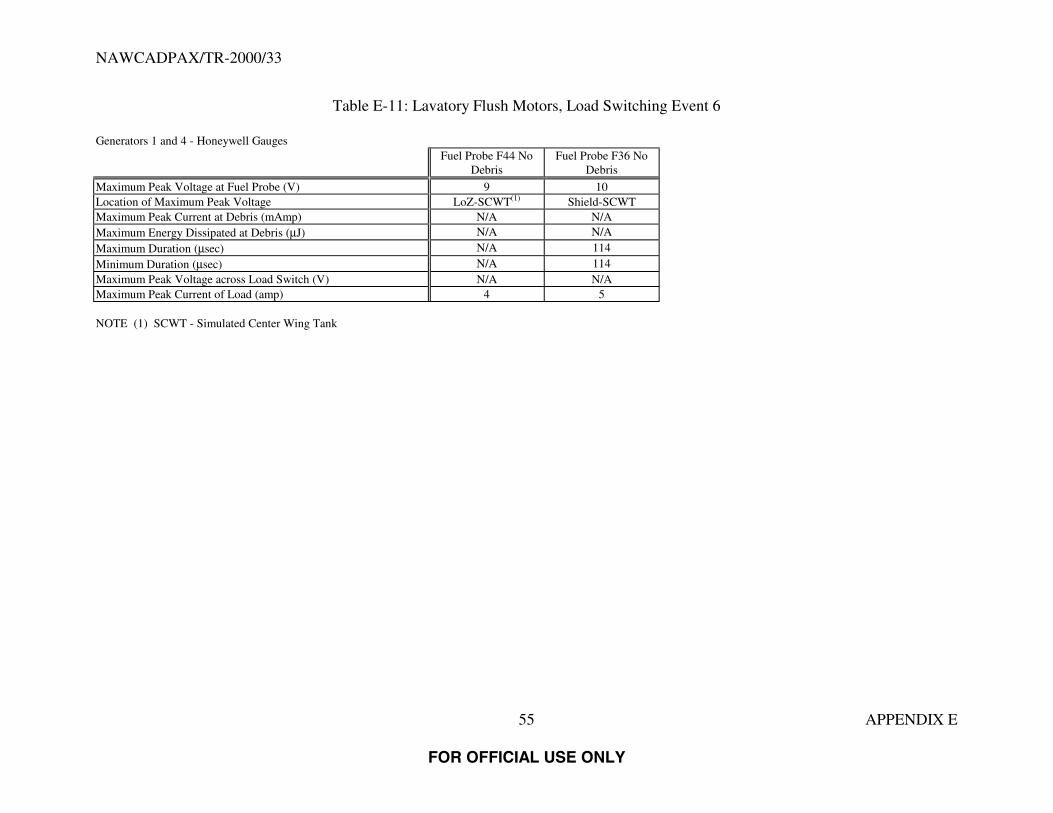
NAWCADPAX/TR-2000/33
55 APPENDIX E
FOR OFFICIAL USE ONLY
Table E-11: Lavatory Flush Motors, Load Switching Event 6
Generators 1 and 4 - Honeywell GaugesFuel Probe F44 No
DebrisFuel Probe F36 No
Debris
Maximum Peak Voltage at Fuel Probe (V) 9 10Location of Maximum Peak Voltage LoZ-SCWT(1) Shield-SCWTMaximum Peak Current at Debris (mAmp) N/A N/AMaximum Energy Dissipated at Debris (µJ) N/A N/AMaximum Duration (µsec) N/A 114Minimum Duration (µsec) N/A 114Maximum Peak Voltage across Load Switch (V) N/A N/AMaximum Peak Current of Load (amp) 4 5
NOTE (1) SCWT - Simulated Center Wing Tank

NAWCADPAX/TR-2000/33
56
FOR OFFICIAL USE ONLY
THIS PAGE INTENTIONALLY LEFT BLANK

NAWCADPAX/TR-2000/33
57 APPENDIX F
FOR OFFICIAL USE ONLY
APPENDIX FVOLTAGE HARMONIC’S ON CAPTAIN’S CHANNEL OF COCKPIT VOICE RECORDER
Total Harmonic RMS Voltage LevelDistortion of the
Electrical Load Condition (% THD) Fundamental mV Spectrum Trace
Base Load Case 33.13 110.4 Trace 1Base Load Case 33.78 105.3 Trace 2Storm Lights On 32.72 106.2 Trace 3Overhead Panel Lights Off 33.03 107.4 Trace 4Instrument Lights Captain-side Off 31.03 114.2 Trace 5Upper Deck Light Breaker Pulled 37.23 96.2 Trace 6Upper Deck Galley Equipment On 33.00 103.5 Trace 7Keying the Passenger Address Microphone 76.87 73.9 Trace 8Keying the Passenger Address Microphone 81.02 70.4 Trace 9Passenger Address Pressed on Captain’s Audio 80.47 67.0 Trace 10Open Split System Breaker 64.35 67.7 Trace 11Open GCB 3 and GCB 4 31.54 115.5 Trace 12All GCB’s Open, No Emergency Lights 48.76 11.4 Trace 13All GCB’s Open, No Emergency Lights 46.20 12.4 Trace 14All GCB’s Closed, No Emergency Lights (Spectrum taken immediately after closing GCB’s) 12.25 294.5 Trace 15All GCB’s Open, with Emergency Lights 47.58 12.0 Trace 16All GCB’s Closed (Spectrum taken immediately after closing GCB’s) 12.09 344.8 Trace 17GCB 1 and GCB 2 Open 32.06 106.5 Trace18Breaker Pulled for TRU1 58.66 99.9 Trace 19Breaker Pulled for TRU2 12.30 329.8 Trace 20Breaker Pulled for TRU2 12.09 327.7 Trace 21Breaker Pulled for TRU3 31.96 100.8 Trace 22Essential Power Selector to BUS 3 11.98 322.8 Trace 23Essential Power Selector to BUS 2 12.48 328.2 Trace 24Essential Power Selector to BUS 1 12.51 298.1 Trace 25All TRU Breakers Pulled 18.72 336.0 Trace 26All TRU Breakers Pulled 18.86 322.6 Trace 27

NAWCADPAX/TR-2000/33
58 APPENDIX F
FOR OFFICIAL USE ONLY
Figure F-1A: Spectrum for Base Load Case

NAWCADPAX/TR-2000/33
59 APPENDIX F
FOR OFFICIAL USE ONLY
Figure F-1B: Spectrum for Base Load Case (Cont’d)

NAWCADPAX/TR-2000/33
60 APPENDIX F
FOR OFFICIAL USE ONLY
Figure F-1C: Spectrum for Base Load Case (Cont’d)

NAWCADPAX/TR-2000/33
61 APPENDIX F
FOR OFFICIAL USE ONLY
Figure F-2A: Spectrum for Base Load Case (Repeated)

NAWCADPAX/TR-2000/33
62 APPENDIX F
FOR OFFICIAL USE ONLY
Figure F-2B: Spectrum for Base Load Case (Repeated) (Cont’d)

NAWCADPAX/TR-2000/33
63 APPENDIX F
FOR OFFICIAL USE ONLY
Figure F-2C: Spectrum for Base Load Case (Repeated) (Cont’d)

NAWCADPAX/TR-2000/33
64 APPENDIX F
FOR OFFICIAL USE ONLY
Figure F-3A: Spectrum for Storm Lights On

NAWCADPAX/TR-2000/33
65 APPENDIX F
FOR OFFICIAL USE ONLY
Figure F-3B: Spectrum for Storm Lights On (Cont’d)

NAWCADPAX/TR-2000/33
66 APPENDIX F
FOR OFFICIAL USE ONLY
Figure F-3C: Spectrum for Storm Lights On (Cont’d)

NAWCADPAX/TR-2000/33
67 APPENDIX F
FOR OFFICIAL USE ONLY
Figure F-4A: Spectrum for Overhead Panel Lights Off
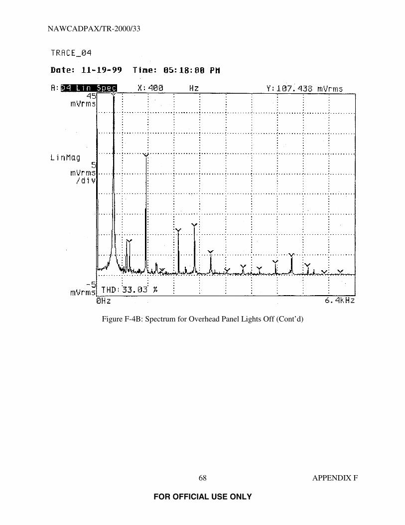
NAWCADPAX/TR-2000/33
68 APPENDIX F
FOR OFFICIAL USE ONLY
Figure F-4B: Spectrum for Overhead Panel Lights Off (Cont’d)

NAWCADPAX/TR-2000/33
69 APPENDIX F
FOR OFFICIAL USE ONLY
Figure F-4C: Spectrum for Overhead Panel Lights Off (Cont’d)

NAWCADPAX/TR-2000/33
70 APPENDIX F
FOR OFFICIAL USE ONLY
Figure F-5A: Spectrum for Instrument Lights Captain-side Off

NAWCADPAX/TR-2000/33
71 APPENDIX F
FOR OFFICIAL USE ONLY
Figure F-5B: Spectrum for Instrument Lights Captain-side Off (Cont’d)

NAWCADPAX/TR-2000/33
72 APPENDIX F
FOR OFFICIAL USE ONLY
Figure F-5C: Spectrum for Instrument Lights Captain-side Off (Cont’d)

NAWCADPAX/TR-2000/33
73 APPENDIX F
FOR OFFICIAL USE ONLY
Figure F-6A: Spectrum for Upper Deck Light Breaker Pulled

NAWCADPAX/TR-2000/33
74 APPENDIX F
FOR OFFICIAL USE ONLY
Figure F-6B: Spectrum for Upper Deck Light Breaker Pulled (Cont’d)

NAWCADPAX/TR-2000/33
75 APPENDIX F
FOR OFFICIAL USE ONLY
Figure F-6C: Spectrum for Upper Deck Light Breaker Pulled (Cont’d)

NAWCADPAX/TR-2000/33
76 APPENDIX F
FOR OFFICIAL USE ONLY
Figure F-7A: Spectrum for Upper Deck Galley Equipment On
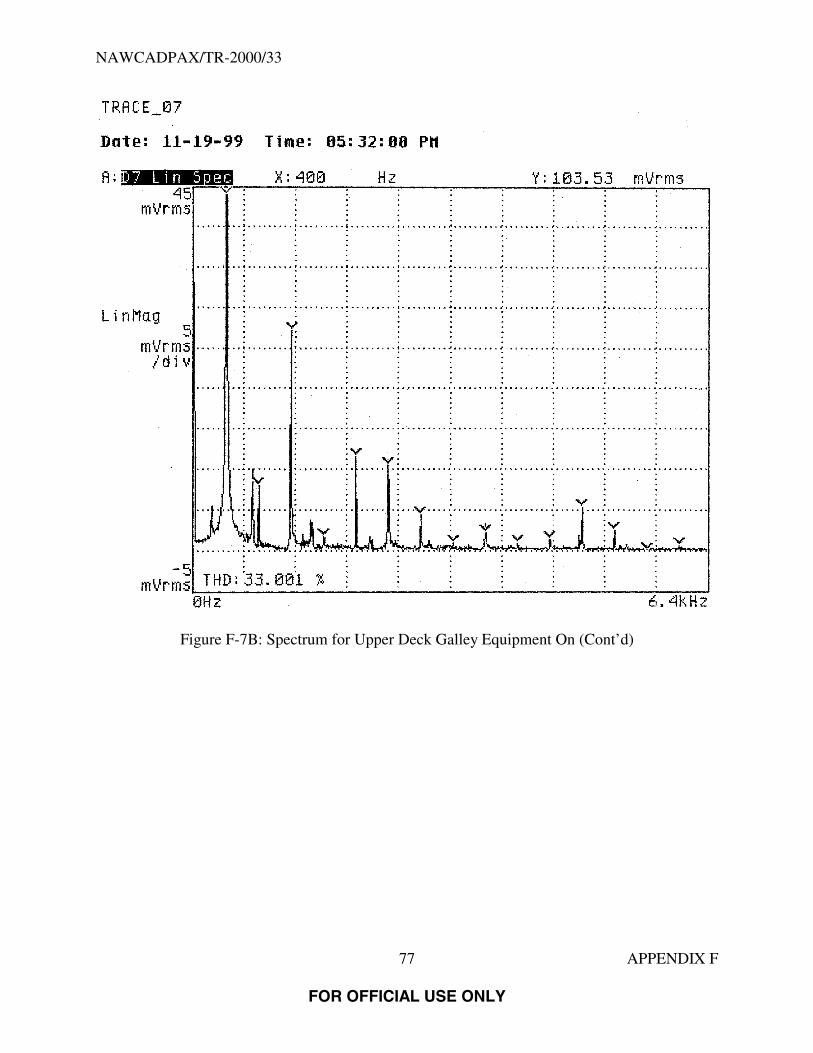
NAWCADPAX/TR-2000/33
77 APPENDIX F
FOR OFFICIAL USE ONLY
Figure F-7B: Spectrum for Upper Deck Galley Equipment On (Cont’d)

NAWCADPAX/TR-2000/33
78 APPENDIX F
FOR OFFICIAL USE ONLY
Figure F-7C: Spectrum for Upper Deck Galley Equipment On (Cont’d)

NAWCADPAX/TR-2000/33
79 APPENDIX F
FOR OFFICIAL USE ONLY
Figure F-8A: Spectrum for Keying the Passenger Address Microphone

NAWCADPAX/TR-2000/33
80 APPENDIX F
FOR OFFICIAL USE ONLY
Figure F-8B: Spectrum for Keying the Passenger Address Microphone (Cont’d)
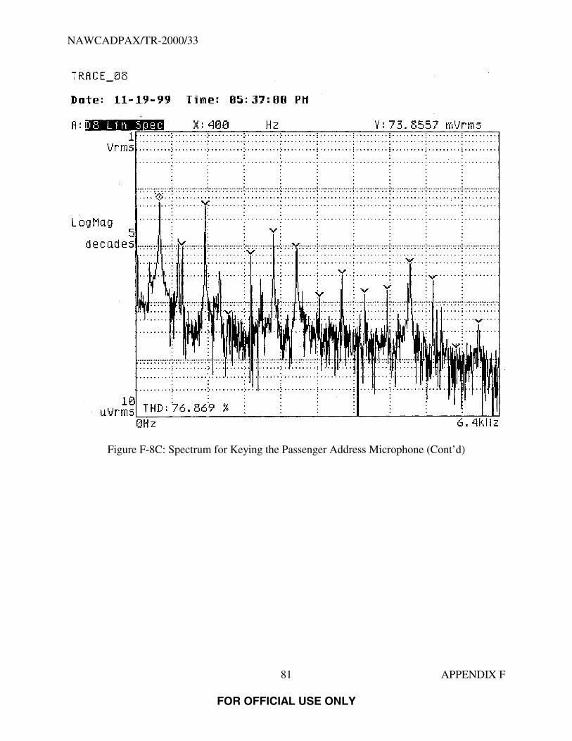
NAWCADPAX/TR-2000/33
81 APPENDIX F
FOR OFFICIAL USE ONLY
Figure F-8C: Spectrum for Keying the Passenger Address Microphone (Cont’d)
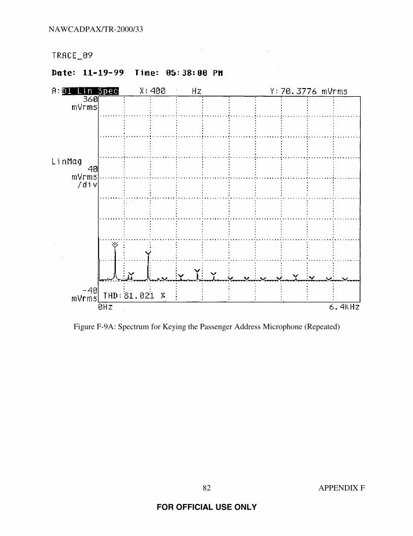
NAWCADPAX/TR-2000/33
82 APPENDIX F
FOR OFFICIAL USE ONLY
Figure F-9A: Spectrum for Keying the Passenger Address Microphone (Repeated)

NAWCADPAX/TR-2000/33
83 APPENDIX F
FOR OFFICIAL USE ONLY
Figure F-9B: Spectrum for Keying the Passenger Address Microphone (Repeated) (Cont’d)

NAWCADPAX/TR-2000/33
84 APPENDIX F
FOR OFFICIAL USE ONLY
Figure F-9C: Spectrum for Keying the Passenger Address Microphone (Repeated) (Cont’d)

NAWCADPAX/TR-2000/33
85 APPENDIX F
FOR OFFICIAL USE ONLY
Figure F-10A: Spectrum for Passenger Address Pressed on Captain’s Audio

NAWCADPAX/TR-2000/33
86 APPENDIX F
FOR OFFICIAL USE ONLY
Figure F-10B: Spectrum for Passenger Address Pressed on Captain’s Audio (Cont’d)
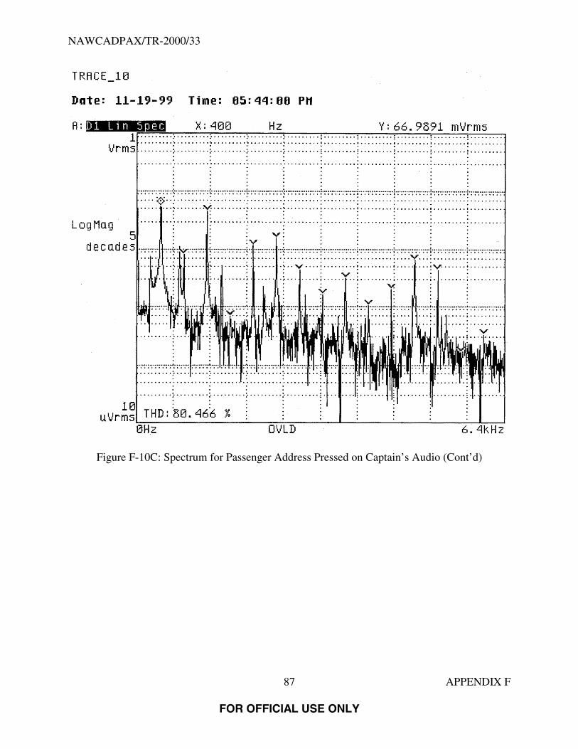
NAWCADPAX/TR-2000/33
87 APPENDIX F
FOR OFFICIAL USE ONLY
Figure F-10C: Spectrum for Passenger Address Pressed on Captain’s Audio (Cont’d)

NAWCADPAX/TR-2000/33
88 APPENDIX F
FOR OFFICIAL USE ONLY
Figure F-11A: Spectrum for Open Split System Breaker

NAWCADPAX/TR-2000/33
89 APPENDIX F
FOR OFFICIAL USE ONLY
Figure F-11B: Spectrum for Open Split System Breaker (Cont’d)

NAWCADPAX/TR-2000/33
90 APPENDIX F
FOR OFFICIAL USE ONLY
Figure F-11C: Spectrum for Open Split System Breaker (Cont’d)

NAWCADPAX/TR-2000/33
91 APPENDIX F
FOR OFFICIAL USE ONLY
Figure F-12A: Spectrum for Open GCB 3 and GCB 4

NAWCADPAX/TR-2000/33
92 APPENDIX F
FOR OFFICIAL USE ONLY
Figure F-12B: Spectrum for Open GCB 3 and GCB 4 (Cont’d)

NAWCADPAX/TR-2000/33
93 APPENDIX F
FOR OFFICIAL USE ONLY
Figure F-12C: Spectrum for Open GCB 3 and GCB 4 (Cont’d)

NAWCADPAX/TR-2000/33
94 APPENDIX F
FOR OFFICIAL USE ONLY
Figure F-13A: Spectrum for All GCB’s Open, No Emergency Lights
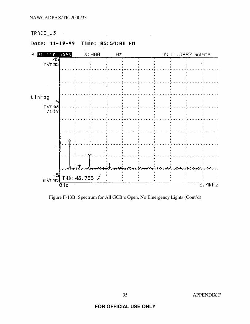
NAWCADPAX/TR-2000/33
95 APPENDIX F
FOR OFFICIAL USE ONLY
Figure F-13B: Spectrum for All GCB’s Open, No Emergency Lights (Cont’d)

NAWCADPAX/TR-2000/33
96 APPENDIX F
FOR OFFICIAL USE ONLY
Figure F-13C: Spectrum for All GCB’s Open, No Emergency Lights (Cont’d)

NAWCADPAX/TR-2000/33
97 APPENDIX F
FOR OFFICIAL USE ONLY
Figure F-14A: Spectrum for All GCB’s Open, No Emergency Lights (Repeated)

NAWCADPAX/TR-2000/33
98 APPENDIX F
FOR OFFICIAL USE ONLY
Figure F-14B: Spectrum for All GCB’s Open, No Emergency Lights (Repeated) (Cont’d)
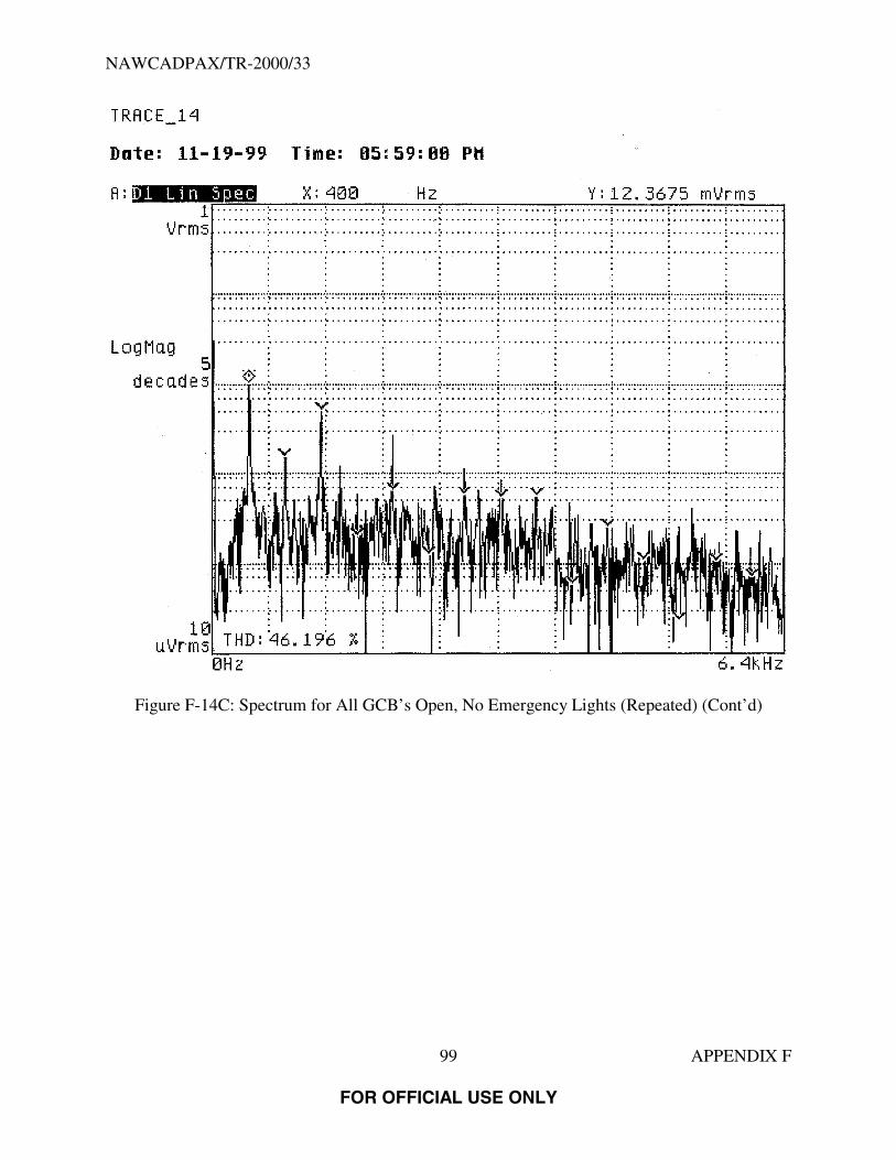
NAWCADPAX/TR-2000/33
99 APPENDIX F
FOR OFFICIAL USE ONLY
Figure F-14C: Spectrum for All GCB’s Open, No Emergency Lights (Repeated) (Cont’d)

NAWCADPAX/TR-2000/33
100 APPENDIX F
FOR OFFICIAL USE ONLY
Figure F-15A: Spectrum for All GCB’s Closed, No Emergency Lights(Spectrum taken immediately after closing GCB’s)

NAWCADPAX/TR-2000/33
101 APPENDIX F
FOR OFFICIAL USE ONLY
Figure F-15B: Spectrum for All GCB’s Closed, No Emergency Lights (Cont’d)(Spectrum taken immediately after closing GCB’s)

NAWCADPAX/TR-2000/33
102 APPENDIX F
FOR OFFICIAL USE ONLY
Figure F-15C: Spectrum for All GCB’s Closed, No Emergency Lights (Cont’d)(Spectrum taken immediately after closing GCB’s)
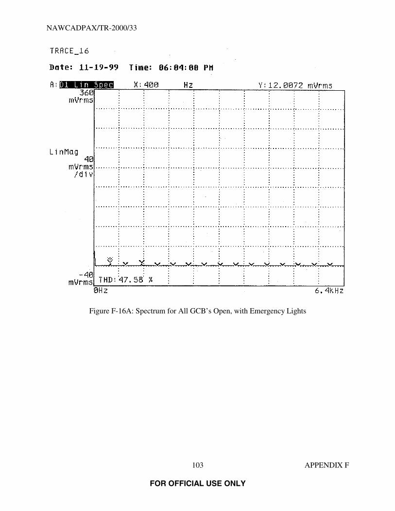
NAWCADPAX/TR-2000/33
103 APPENDIX F
FOR OFFICIAL USE ONLY
Figure F-16A: Spectrum for All GCB’s Open, with Emergency Lights
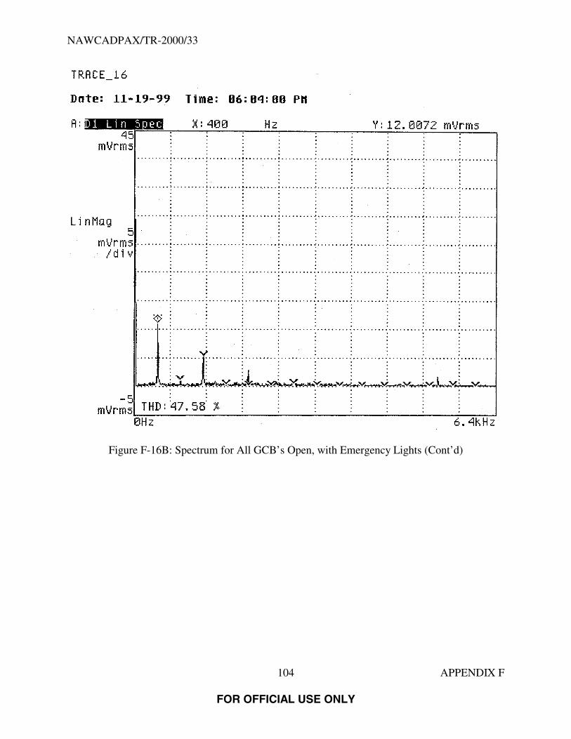
NAWCADPAX/TR-2000/33
104 APPENDIX F
FOR OFFICIAL USE ONLY
Figure F-16B: Spectrum for All GCB’s Open, with Emergency Lights (Cont’d)
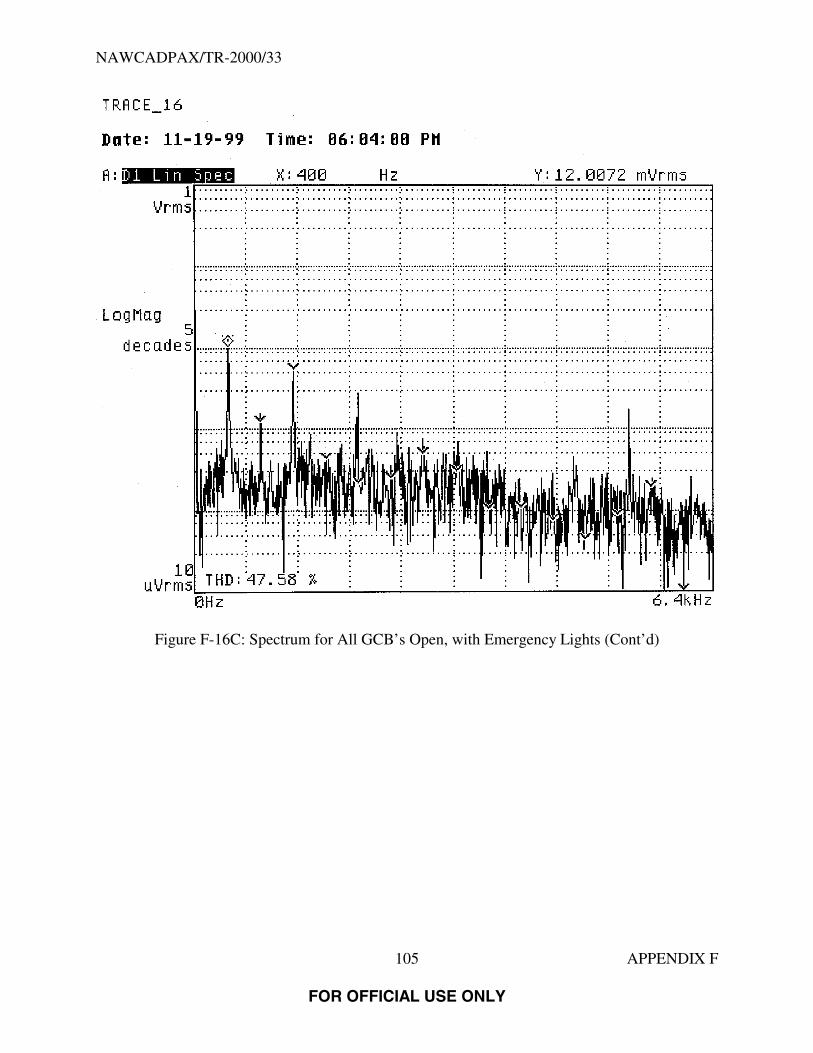
NAWCADPAX/TR-2000/33
105 APPENDIX F
FOR OFFICIAL USE ONLY
Figure F-16C: Spectrum for All GCB’s Open, with Emergency Lights (Cont’d)
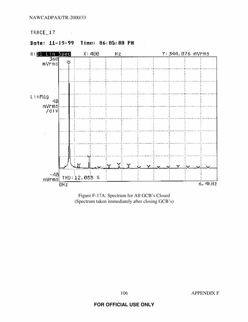
NAWCADPAX/TR-2000/33
106 APPENDIX F
FOR OFFICIAL USE ONLY
Figure F-17A: Spectrum for All GCB’s Closed(Spectrum taken immediately after closing GCB’s)

NAWCADPAX/TR-2000/33
107 APPENDIX F
FOR OFFICIAL USE ONLY
Figure F-17B: Spectrum for All GCB’s Closed (Cont’d)(Spectrum taken immediately after closing GCB’s)
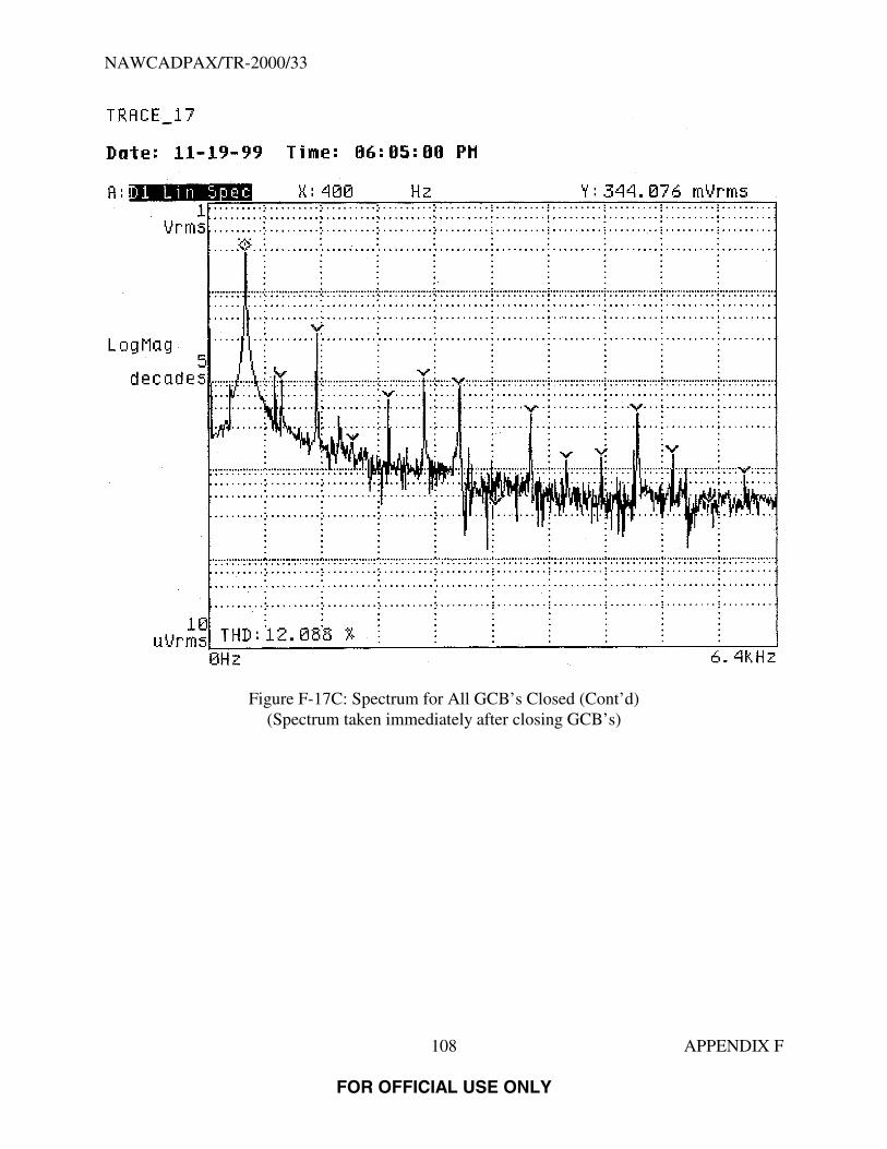
NAWCADPAX/TR-2000/33
108 APPENDIX F
FOR OFFICIAL USE ONLY
Figure F-17C: Spectrum for All GCB’s Closed (Cont’d)(Spectrum taken immediately after closing GCB’s)

NAWCADPAX/TR-2000/33
109 APPENDIX F
FOR OFFICIAL USE ONLY
Figure F-18A: Spectrum for GCB 1 and GCB 2 Open
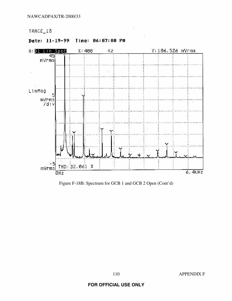
NAWCADPAX/TR-2000/33
110 APPENDIX F
FOR OFFICIAL USE ONLY
Figure F-18B: Spectrum for GCB 1 and GCB 2 Open (Cont’d)

NAWCADPAX/TR-2000/33
111 APPENDIX F
FOR OFFICIAL USE ONLY
Figure F-18C: Spectrum for GCB 1 and GCB 2 Open (Cont’d)
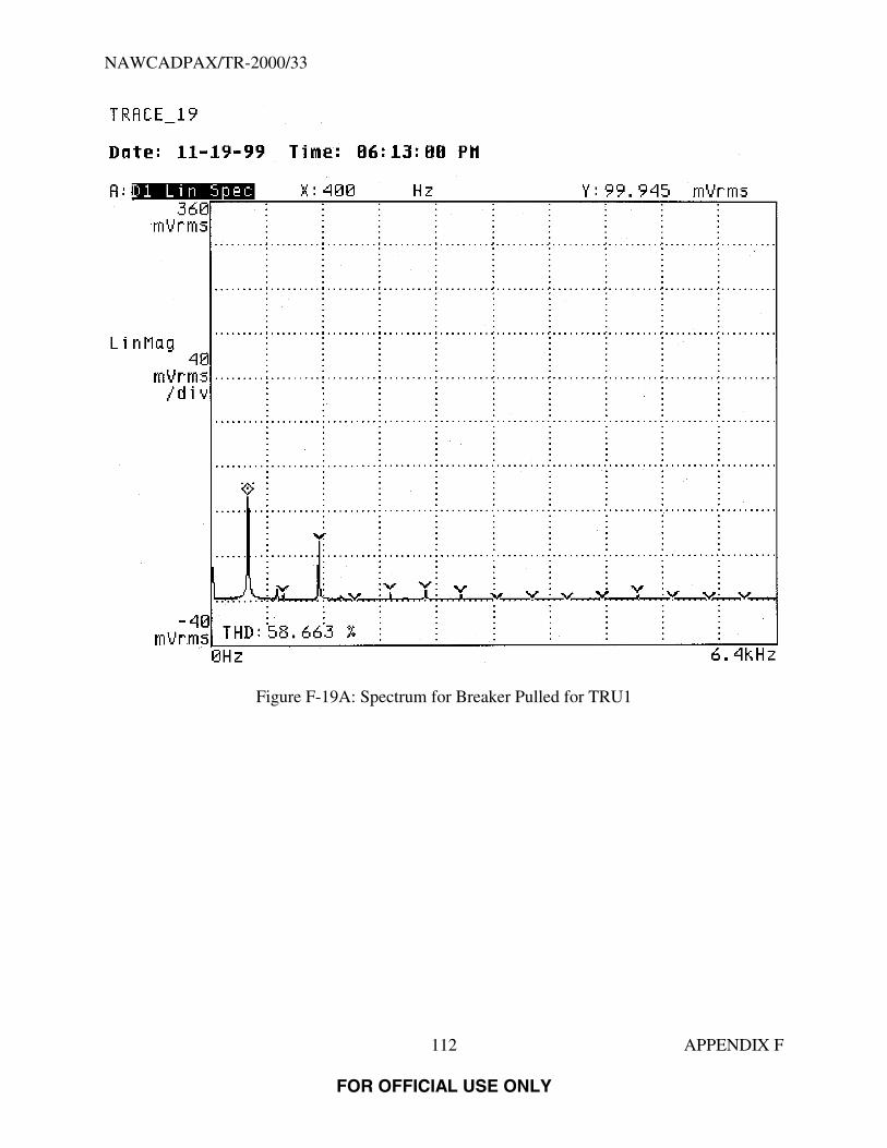
NAWCADPAX/TR-2000/33
112 APPENDIX F
FOR OFFICIAL USE ONLY
Figure F-19A: Spectrum for Breaker Pulled for TRU1
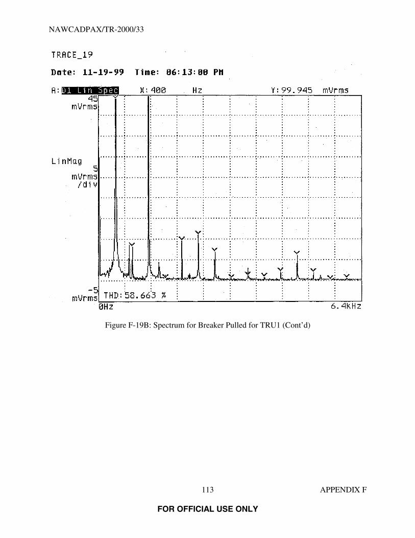
NAWCADPAX/TR-2000/33
113 APPENDIX F
FOR OFFICIAL USE ONLY
Figure F-19B: Spectrum for Breaker Pulled for TRU1 (Cont’d)

NAWCADPAX/TR-2000/33
114 APPENDIX F
FOR OFFICIAL USE ONLY
Figure F-19C: Spectrum for Breaker Pulled for TRU1 (Cont’d)

NAWCADPAX/TR-2000/33
115 APPENDIX F
FOR OFFICIAL USE ONLY
Figure F-20A: Spectrum for Breaker Pulled for TRU2

NAWCADPAX/TR-2000/33
116 APPENDIX F
FOR OFFICIAL USE ONLY
Figure F-20B: Spectrum for Breaker Pulled for TRU2 (Cont’d)

NAWCADPAX/TR-2000/33
117 APPENDIX F
FOR OFFICIAL USE ONLY
Figure F-20C: Spectrum for Breaker Pulled for TRU2 (Cont’d)

NAWCADPAX/TR-2000/33
118 APPENDIX F
FOR OFFICIAL USE ONLY
Figure F-21A: Spectrum for Breaker Pulled for TRU2 (Repeated)

NAWCADPAX/TR-2000/33
119 APPENDIX F
FOR OFFICIAL USE ONLY
Figure F-21B: Spectrum for Breaker Pulled for TRU2 (Repeated) (Cont’d)

NAWCADPAX/TR-2000/33
120 APPENDIX F
FOR OFFICIAL USE ONLY
Figure F-21C: Spectrum for Breaker Pulled for TRU2 (Repeated) (Cont’d)

NAWCADPAX/TR-2000/33
121 APPENDIX F
FOR OFFICIAL USE ONLY
Figure F-22A: Spectrum for Breaker Pulled for TRU3
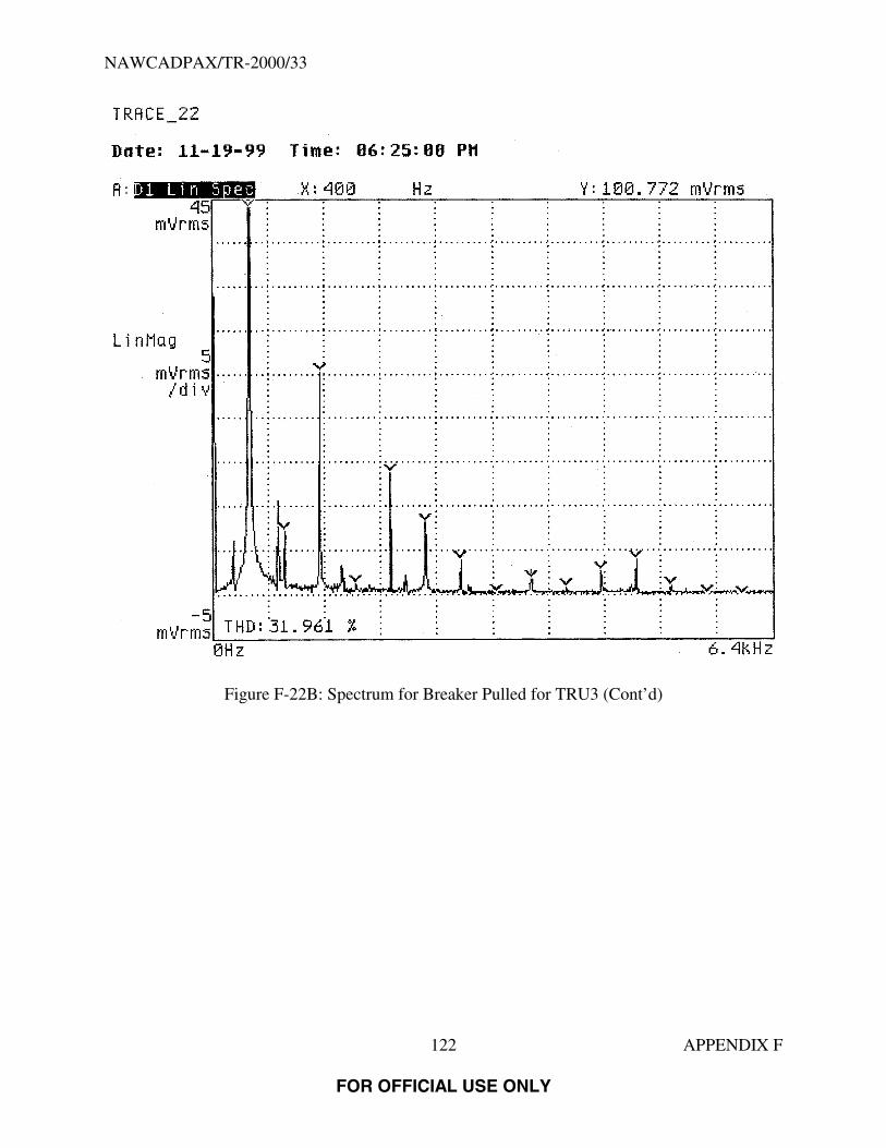
NAWCADPAX/TR-2000/33
122 APPENDIX F
FOR OFFICIAL USE ONLY
Figure F-22B: Spectrum for Breaker Pulled for TRU3 (Cont’d)

NAWCADPAX/TR-2000/33
123 APPENDIX F
FOR OFFICIAL USE ONLY
Figure F-22C: Spectrum for Breaker Pulled for TRU3 (Cont’d)
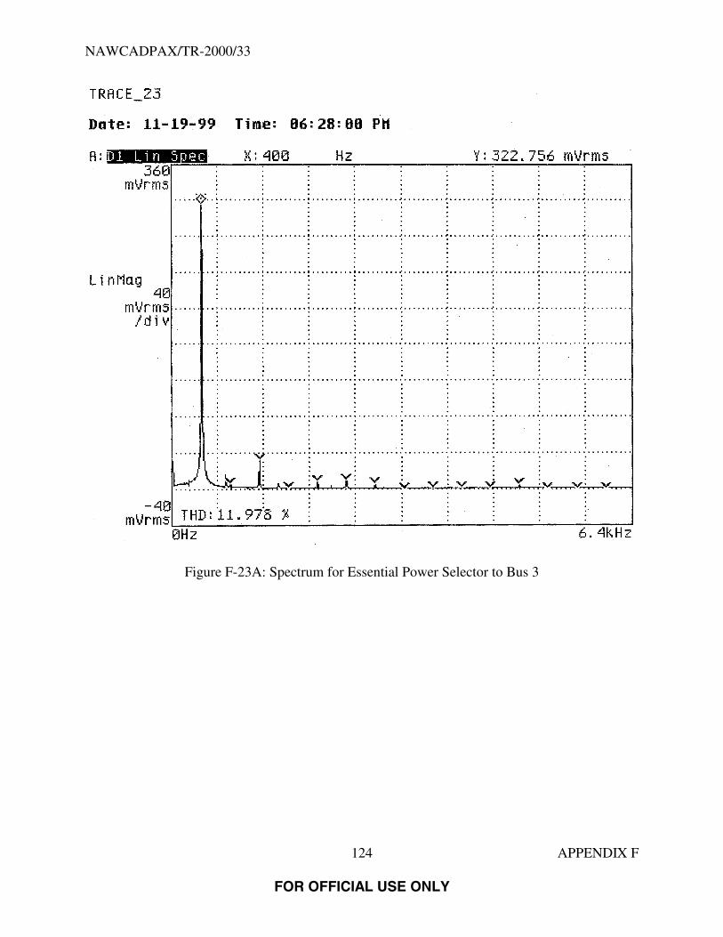
NAWCADPAX/TR-2000/33
124 APPENDIX F
FOR OFFICIAL USE ONLY
Figure F-23A: Spectrum for Essential Power Selector to Bus 3

NAWCADPAX/TR-2000/33
125 APPENDIX F
FOR OFFICIAL USE ONLY
Figure F-23B: Spectrum for Essential Power Selector to Bus 3 (Cont’d)

NAWCADPAX/TR-2000/33
126 APPENDIX F
FOR OFFICIAL USE ONLY
Figure F-23C: Spectrum for Essential Power Selector to Bus 3 (Cont’d)

NAWCADPAX/TR-2000/33
127 APPENDIX F
FOR OFFICIAL USE ONLY
Figure F-24A: Spectrum for Essential Power Selector to Bus 2
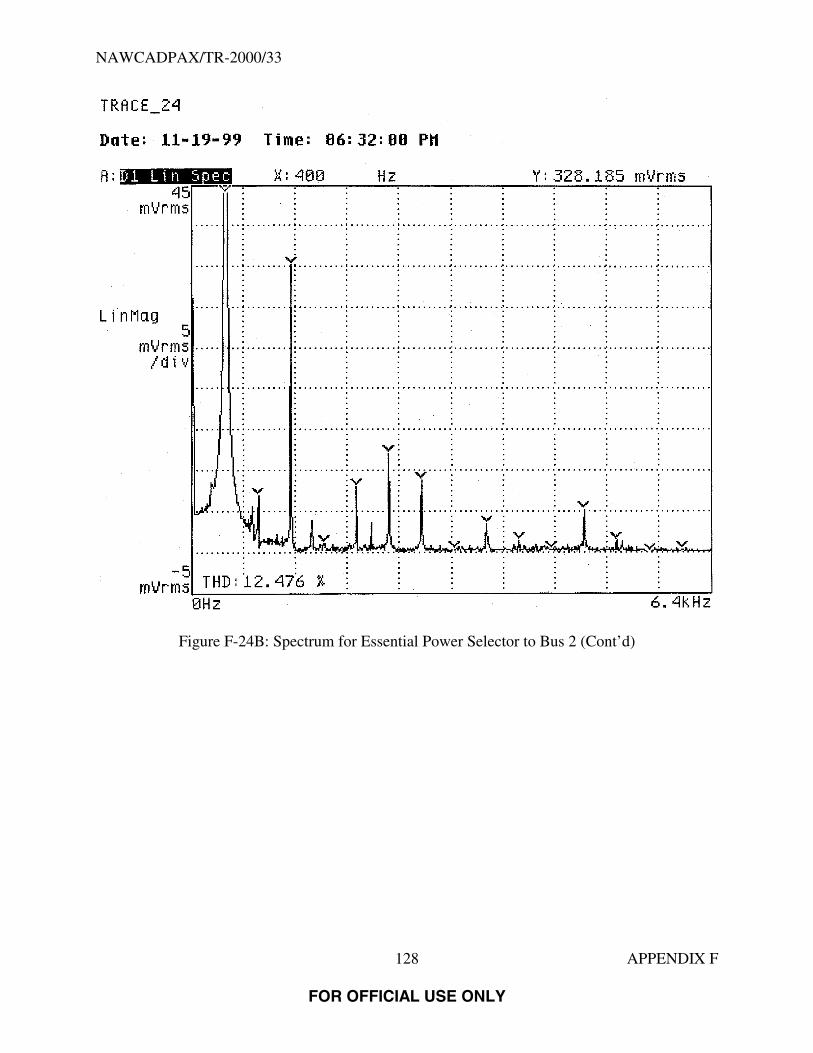
NAWCADPAX/TR-2000/33
128 APPENDIX F
FOR OFFICIAL USE ONLY
Figure F-24B: Spectrum for Essential Power Selector to Bus 2 (Cont’d)
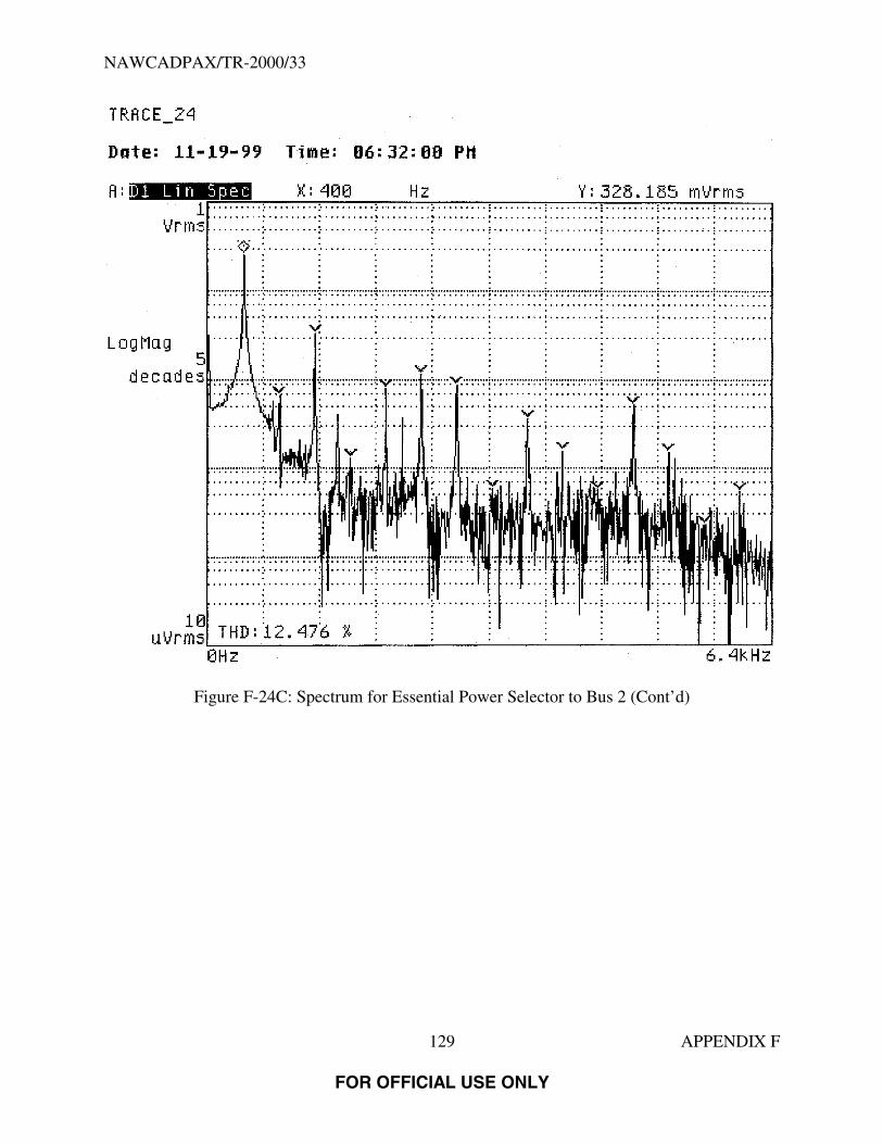
NAWCADPAX/TR-2000/33
129 APPENDIX F
FOR OFFICIAL USE ONLY
Figure F-24C: Spectrum for Essential Power Selector to Bus 2 (Cont’d)

NAWCADPAX/TR-2000/33
130 APPENDIX F
FOR OFFICIAL USE ONLY
Figure F-25A: Spectrum for Essential Power Selector to Bus 1

NAWCADPAX/TR-2000/33
131 APPENDIX F
FOR OFFICIAL USE ONLY
Figure F-25B: Spectrum for Essential Power Selector to Bus 1 (Cont’d)

NAWCADPAX/TR-2000/33
132 APPENDIX F
FOR OFFICIAL USE ONLY
Figure F-25C: Spectrum for Essential Power Selector to Bus 1 (Cont’d)
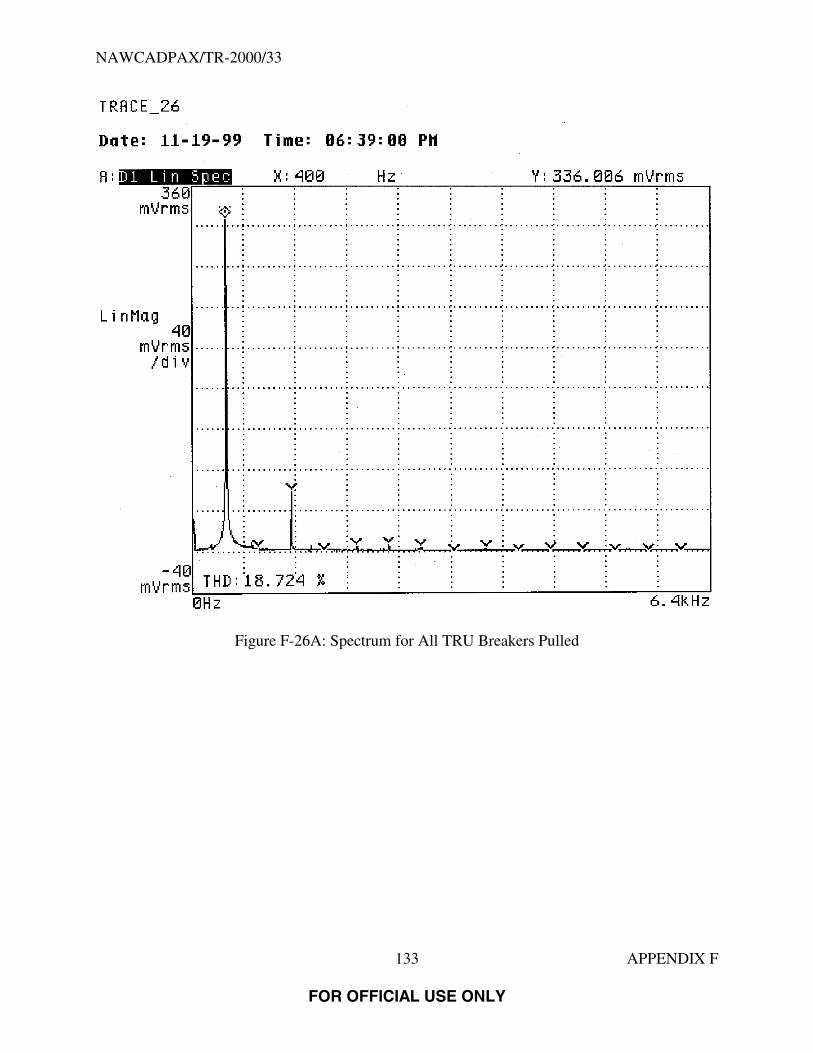
NAWCADPAX/TR-2000/33
133 APPENDIX F
FOR OFFICIAL USE ONLY
Figure F-26A: Spectrum for All TRU Breakers Pulled

NAWCADPAX/TR-2000/33
134 APPENDIX F
FOR OFFICIAL USE ONLY
Figure F-26B: Spectrum for All TRU Breakers Pulled (Cont’d)

NAWCADPAX/TR-2000/33
135 APPENDIX F
FOR OFFICIAL USE ONLY
Figure F-26C: Spectrum for All TRU Breakers Pulled (Cont’d)

NAWCADPAX/TR-2000/33
136 APPENDIX F
FOR OFFICIAL USE ONLY
Figure F-27A: Spectrum for All TRU Breakers Pulled (Repeated)

NAWCADPAX/TR-2000/33
137 APPENDIX F
FOR OFFICIAL USE ONLY
Figure F-27B: Spectrum for All TRU Breakers Pulled (Repeated) (Cont’d)

NAWCADPAX/TR-2000/33
138 APPENDIX F
FOR OFFICIAL USE ONLY
Figure F-27C: Spectrum for All TRU Breakers Pulled (Repeated) (Cont’d)

NAWCADPAX/TR-2000/33
139
FOR OFFICIAL USE ONLY
DISTRIBUTION:
National Transportation Safety Board (15)NAVAIRSYSCOM (AIR-4.4.4.2) (5)NAVTESTWINGLANT Patuxent River, Maryland (55TW01A) (1)NAVAIRWARCENACDIV Patuxent River, Maryland (4.4.4.1) (1)NAVAIRWARCENACDIV Patuxent River, Maryland (4.11) (1)NAVAIRWARCENACDIV Patuxent River, Maryland (Technical Publishing Team) (1)DTIC (1)

FOR OFFICIAL USE ONLY
FOR OFFICIAL USE ONLY