body jet product code: jet2 c / jet3 c telephone help …...aftercare instructions your fitting has...
TRANSCRIPT

AFTERCARE INSTRUCTIONS Your fitting has a high quality finish and should be treated with care to preserve the visible surfaces. All surface finishes will wear if not cleaned correctly, the only safe way to clean your fitting is to wipe with a soft damp cloth. Stains can be removed using washing up liquid. All bath cleaning powders and liquids will damage the surface of your fitting even the non-scratch cleaners. GUARANTEE All products are manufactured to the highest standards and a 5 year guarantee covers any defect in manufacture. As gold and special effect finishes are softer than chromium plate, special care must be taken when cleaning; a 3 year guarantee covers these finishes. NOTE: - the 5 year guarantee is invalidated if damaged by any waterborne debris. In the interests of continuous product development we reserve the right to alter specification as necessary
PRODUCT CODE: JET2 C / JET3 C
TELEPHONE HELP LINE! +44 (0) 870 4425553 Bristan Limited Birch Coppice Business Park Dordon Tamworth Staffordshire B78 1SG UK Web site: www.bristan.com Telephone: +44 (0) 870 4425556 Facsimile: +44 (0) 870 4425554 Email: [email protected] (FI JET2/3) (Rev. D1) (B)
Body Jet Fitting Instructions & Content list Please keep these instructions for future reference and request of replacement parts
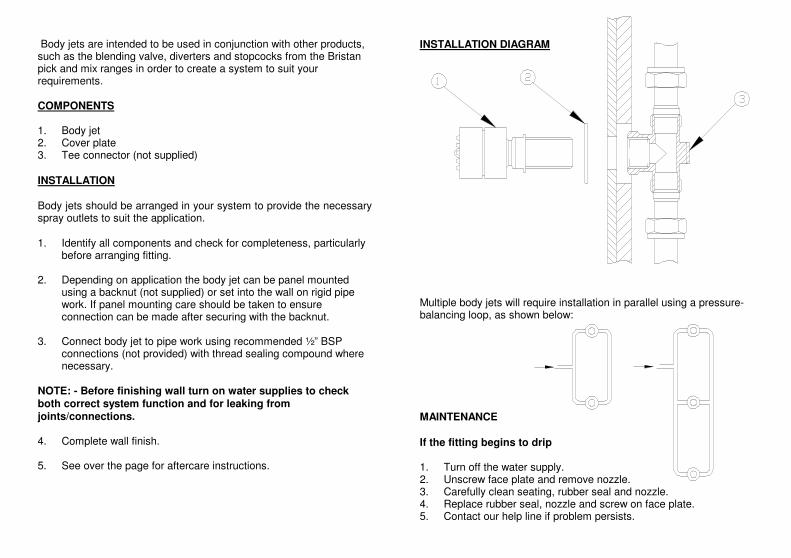
Body jets are intended to be used in conjunction with other products, such as the blending valve, diverters and stopcocks from the Bristan pick and mix ranges in order to create a system to suit your requirements. COMPONENTS 1. Body jet 2. Cover plate 3. Tee connector (not supplied) INSTALLATION Body jets should be arranged in your system to provide the necessary spray outlets to suit the application. 1. Identify all components and check for completeness, particularly
before arranging fitting. 2. Depending on application the body jet can be panel mounted
using a backnut (not supplied) or set into the wall on rigid pipe work. If panel mounting care should be taken to ensure connection can be made after securing with the backnut.
3. Connect body jet to pipe work using recommended ½” BSP
connections (not provided) with thread sealing compound where necessary.
NOTE: - Before finishing wall turn on water supplies to check both correct system function and for leaking from joints/connections. 4. Complete wall finish. 5. See over the page for aftercare instructions.
INSTALLATION DIAGRAM Multiple body jets will require installation in parallel using a pressure-balancing loop, as shown below: MAINTENANCE If the fitting begins to drip 1. Turn off the water supply. 2. Unscrew face plate and remove nozzle. 3. Carefully clean seating, rubber seal and nozzle. 4. Replace rubber seal, nozzle and screw on face plate. 5. Contact our help line if problem persists.


Slim Line Square/RoundFixed Shower Head
Fitting Instructions
Please keep these instructions for future reference.(FI FH SL) (REV D1)
GUARANTEEAll products are manufactured to the highest standards and a 5 year guaranteecovers any defect in manufacture.
In the interests of continuous product development we reserve the right to alterspecification as necessary
Bristan Group LimitedBirch Coppice Business ParkDordonTamworthStaffordshireB78 1SGUK
A Masco CompanyWebsite: www.bristan.comTelephone: 0844 701 6274Facsimile: 0844 701 6275Email:
All products must have access for servicing or replacement during the life ofthe product.
THIS BOOKLET COVERS PRODUCT CODES:
FH SLRD01 C FH SLSQ01 CFH SLRD02 C FH SLSQ02 CFH SLRD03 C FH SLSQ03 C
TELEPHONE HELPLINE: 0844 701 6273
Bristan recommend E-Cloth for cleaning all of ourbathroom & kitchen products. Using just water, E-clothgives a smear free, deep clean by breaking up and holdingdirt, which normal cloths leave behind. Order throughyour Bristan stockist. (ORDER CODE: ECLOTH)
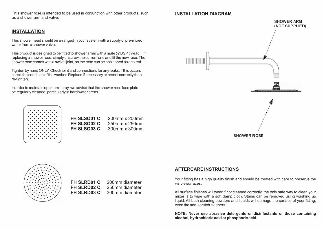
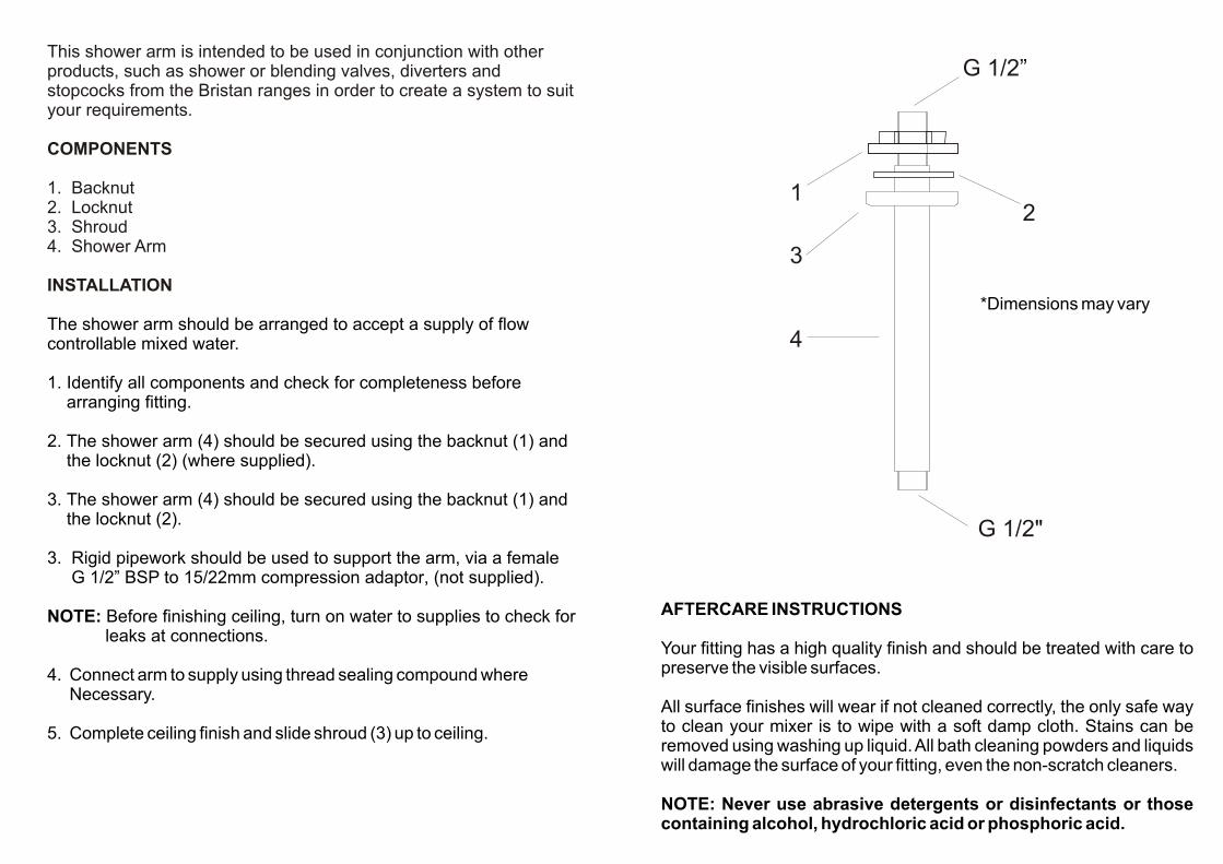
This shower rose is intended to be used in conjunction with other products, suchas a shower arm and valve.
INSTALLATION DIAGRAM
INSTALLATION
This shower head should be arranged in your system with a supply of pre-mixedwater from a shower valve.
This product is designed to be fitted to shower arms with a male ½”BSP thread. Ifreplacing a shower rose, simply unscrew the current one and fit the new rose. Theshower rose comes with a swivel joint, so the rose can be positioned as desired.
Tighten by hand ONLY. Check joint and connections for any leaks, if this occurscheck the condition of the washer. Replace if necessary or reseat correctly thenre-tighten.
In order to maintain optimum spray, we advise that the shower rose face platebe regularly cleaned, particularly in hard water areas.
AFTERCARE INSTRUCTIONS
Your fitting has a high quality finish and should be treated with care to preserve thevisible surfaces.
All surface finishes will wear if not cleaned correctly, the only safe way to clean yourmixer is to wipe with a soft damp cloth. Stains can be removed using washing upliquid. All bath cleaning powders and liquids will damage the surface of your fitting,even the non-scratch cleaners.
NOTE: Never use abrasive detergents or disinfectants or those containingalcohol, hydrochloric acid or phosphoric acid.
FH SLRD01 CFH SLRD02 CFH SLRD03 C
200mm diameter250mm diameter300mm diameter
FH SLSQ01 CFH SLSQ02 CFH SLSQ03 C
200mm x 200mm250mm x 250mm300mm x 300mm

Installation Instructions and User Guide
Thermostatic Recessed Three Control Shower Valve with Stopcock & Two outlet Diverter
Models covered: CAS SHC3DIV C, PM2 SHC3DIV C, TRI SHC3DIV C, PIV SHC3DIV C, ORB SHC3DIV C, GLR SHC3DIV C, BRG SHC3DIV C, DSC SHC3DIV C, HOU SHC3DIV C & SAI SHC3DIV C
Please keep this booklet for future reference.
Installer, when you have read these instructions please ensure you leave them with the user.
Thank you for choosing Bristan, the UK’s leading showers and taps expert. We have designed this product with your enjoyment in mind. To ensure that it works to its full potential, it needs to be fitted correctly. These fitting instructions have been created to give you all of the information you need and, if you need any further help, please do not hesitate to give us a call on 0844 701 6273.
Important Safety Information …………………………………………………..…………..
General Information ……………………………………………………………………………..
Product Features ………………………………………………………………………………….
Specifications ……………………………………………………………………………………….
Dimensions ………………………………………………………………………………….……….
Pack Contents ………………………………………………………………………………………
Prior to Installation …………………………………………………………..………............
Installation …………………………………………………………………………………..……….
Front Access …………………………………………………..……................
Rear Access .…………………………………………………………….………….
Wall Outlet ……………………………………………………………………………
Operating the Shower ………………………………………………………………….……….
Maintenance ………………………………………………………………………………..……….
Adjusting the Temperature …………………………………………………………………..
Troubleshooting …………………………………………………………………………..……….
Notes …………………………………………………………………………………………………...
Guarantee ……………………………………………………………………………………………..
Contents
2 Need help? Give us a call on 0844 701 6273 and speak to one of our trained advisers.
3
4
5
6
7-9
10-16
17
18-22
18-19
20-21
22
23
24
25
26-27
28-29
30-31

Important Safety Information
Need help? Give us a call on 0844 701 6273 and speak to one of our trained advisers. 3
• Please read these instructions thoroughly and retain for future use.
• All products manufactured and supplied by Bristan are safe provided they are installed, used correctly and receive regular maintenance in accordance with these instructions.
• If you are in any doubt about your ability to install this product safely you must employ the services of an experienced qualified plumber.
• These fittings need to be installed in accordance with, and meet the requirements of the Water Supply (Water Fittings) Regulations 1999 and Scottish Byelaws 2004.
• Remove all packaging and check there are no missing or damaged parts.
• Before starting any installation please consider the following:
• Before drilling into walls, check that there are no hidden electrical wires, cables or water supply pipes. This can be checked with the aid of an electronic detector.
• If power tools are used do not forget to: - Wear eye protection - Unplug equipment after use
• Warning: Before installing the new shower valve it is essential that you thoroughly flush through the pipework in order to remove any remaining swarf, solder, etc. Failure to carry out this procedure could cause problems or damage to the workings of the shower valve.
• Fitting isolation valves to the inlet feeds is required for ease of maintenance.
• Access must be made available to the shower valve / mixer body for maintenance /
servicing purposes.
• Warning: Do not operate this product if you suspect it is frozen. Do not site the Mixing Valve where it might be subjected to freezing conditions.
• These shower valves must not be modified in any way as this will invalidate the guarantee.

General Information
4 Need help? Give us a call on 0844 701 6273 and speak to one of our trained advisers.
Recommended Usage
DomesticHeavy Commercial
Light Commercial
Health Care
This product has been tested to the Water Regulations Advisory Scheme (WRAS) and satisfies the requirements of the Water Supply (Water Fittings) Regulations 1999 and current bylaws.
For full Installation Requirements & Notes (IRN) please visit www.wras.co.uk/directory.
BS7600 recommends the temperature of stored water should never exceed 65ºC. A stored water temperature of 60ºC is considered sufficient to meet all normal requirements and will minimise the build up of lime scale in hard water areas.
If the shower valve is installed at low pressure (tank fed), then the minimum distance from the highest installed position of the showerhead to the underside of the cold tank should be at least 1 metre to ensure adequate performance.
Note: Nominally equal (balanced) inlet supply pressures are recommended for optimum performance.
This shower valve should be installed in compliance with the Water Supply (Water Fittings) Regulations1999 and the Scottish Bylaws 2004.
If in doubt, contact a registered plumber or your Local Water Authority or the Secretary of The Institute of Plumbing, address as follows;-
The Institute of Plumbing,64 Station Lane, Hornchurch,Essex, RM12 6NBTel: 01708 472791

Product Features
Need help? Give us a call on 0844 701 6273 and speak to one of our trained advisers. 5
1. Two outlet diverterThis outlet allows the user to divert the flow of water from one water outlet to another. E.g. Fixed rigid riser or an adjustable riser.
2. Temperature controlAdjustable temperature control.
Turn the handle clockwise for a cooler temperature.
Turn the handle anti-clockwise for a hotter temperature.
3. Single outlet stopcockAllows the user to operate another water outlet e.g. body jets while one outlet from the top diverter is also being used.
This outlet also allows the user to use this outlet independantly.
Note: Both the bottom stopcock and one of the top diverter outlets can be used together. If both of these outlets are used together the flow will be shared between both outlets.
1
2
3
CAS SHC3DIV C shown

Specifications
Inlet connections: 15mm compression with 150mm between centres.
Minimum working pressure: 0.2 bar
Note: This product has been designed to deliver a high flow of water on low pressure systems, however depending on the installation, type of system and shower accessories used, a higher pressure maybe required to optimise the showering experence.
Maximum working pressure: 5 bar
Maximum static pressure: 10.0 bar
Note: Static pressure is the build up of pressure when the valve is closed.
Supply requirements:
Minimum cold water supply temperature: 5ºC.Maximum cold water supply temperature: 25ºC.Maximum hot water supply temperature: 80ºC.
Note: The inlet hot water temperature must be at least 10ºC above the required blend temperature (e.g. shower temperature 43ºC: minimum hot water temperature 53ºC).
System requirements:
Gravity fed hot & cold (Equal pressures)Gravity fed hot & mains cold (Differential pressure, maximum ration 5:1)Unvented systemsInstantaneous water heater (Combination boiler)Pumped system
Note: When using a pumped system we recommend that an essex flange is used.
Important: Minimum wall cavity depth: 35mm
6 Need help? Give us a call on 0844 701 6273 and speak to one of our trained advisers.
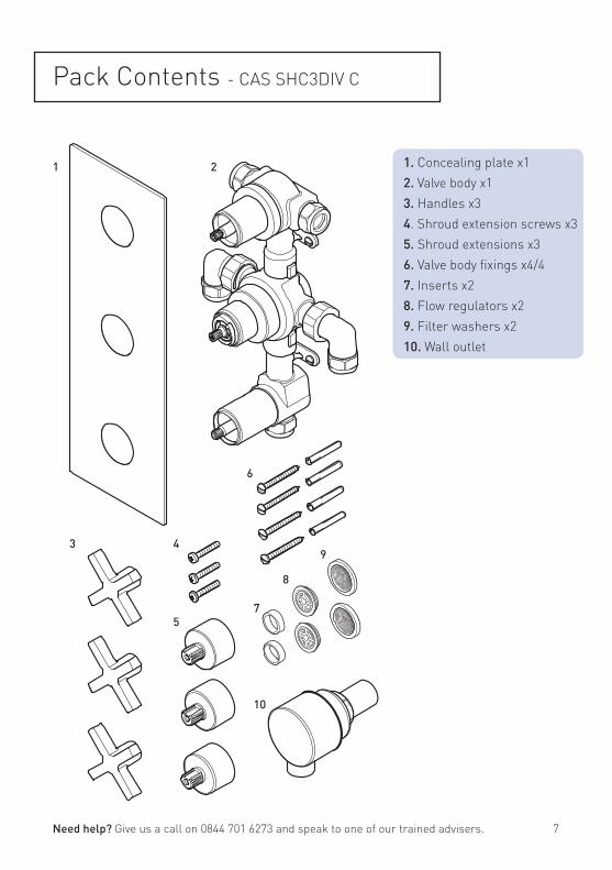
Pack Contents - CAS SHC3DIV C
1
3 4
5
6
7
2 1. Concealing plate x12. Valve body x13. Handles x34. Shroud extension screws x35. Shroud extensions x36. Valve body fixings x4/47. Inserts x28. Flow regulators x29. Filter washers x210. Wall outlet
9
10
8
Need help? Give us a call on 0844 701 6273 and speak to one of our trained advisers. 7

1
3
4
7
2
5
8
6
9
10
Pack Contents - PM2 SHC3DIV C
1. Concealing plate x12. Valve body x13. Handles x34. Extension screws x35. Spline adaptors x36. Valve body fixings x4/47. Inserts x28. Flow regulators x29. Filter washers x210. Wall outlet
8 Need help? Give us a call on 0844 701 6273 and speak to one of our trained advisers.

Pack Contents- TRI SHC3DIV C
1
34
7
2
5
8
6
910
1. Concealing plate x12. Valve body x13. Handles x34. Extension screws x35. Spline adaptors x36. Valve body fixings x4/47. Inserts x28. Flow regulators x29. Filter washers x210. Wall outlet
Need help? Give us a call on 0844 701 6273 and speak to one of our trained advisers. 9

Pack Contents - PIV SHC3DIV C
1
34
7
2
5
8
6
910
1. Concealing plate x12. Valve body x13. Handles x34. Extension screws x35. Spline adaptors x36. Valve body fixings x4/47. Inserts x28. Flow regulators x29. Filter washers x210. Wall outlet
10 Need help? Give us a call on 0844 701 6273 and speak to one of our trained advisers.

Pack Contents - ORB SHC3DIV C
1
3
4
7
2
8
9
10
5
6
1. Concealing plates x32. Valve body x13. Handles x34. Extension screws x35. Spline adaptors x36. Valve body fixings x4/47. Inserts x28. Flow regulators x29. Filter washers x210. Wall outlet
Need help? Give us a call on 0844 701 6273 and speak to one of our trained advisers. 11
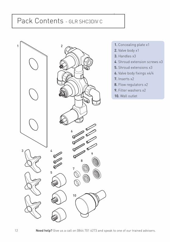
Pack Contents - GLR SHC3DIV C
1
3 4
5
6
7
2 1. Concealing plate x12. Valve body x13. Handles x34. Shroud extension screws x35. Shroud extensions x36. Valve body fixings x4/47. Inserts x28. Flow regulators x29. Filter washers x210. Wall outlet
9
10
8
12 Need help? Give us a call on 0844 701 6273 and speak to one of our trained advisers.
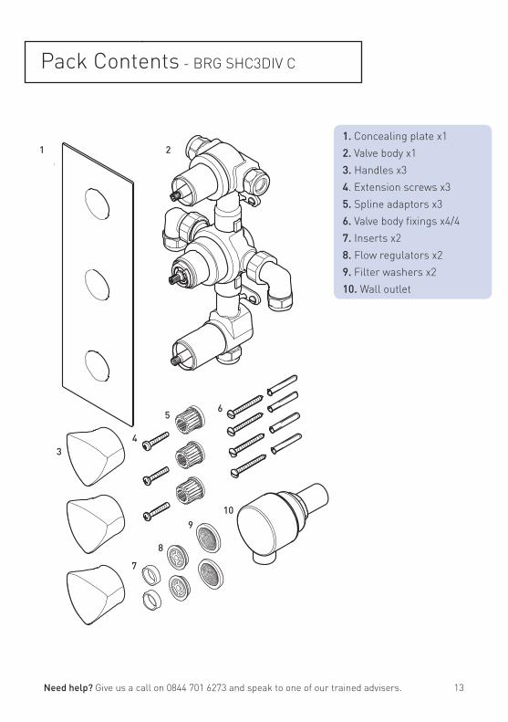
Pack Contents - BRG SHC3DIV C
1. Concealing plate x12. Valve body x13. Handles x34. Extension screws x35. Spline adaptors x36. Valve body fixings x4/47. Inserts x28. Flow regulators x29. Filter washers x210. Wall outlet
1
34
7
2
5
8
6
910
Need help? Give us a call on 0844 701 6273 and speak to one of our trained advisers. 13

1
3
4
7
2
5
8
6
9
10
Pack Contents - DSC SHC3DIV C
1. Concealing plate x12. Valve body x13. Handles x34. Extension screws x35. Spline adaptors x36. Valve body fixings x4/47. Inserts x28. Flow regulators x29. Filter washers x210. Wall outlet
14 Need help? Give us a call on 0844 701 6273 and speak to one of our trained advisers.

Pack Contents - HOU SHC3DIV C
1. Concealing plate x12. Valve body x13. Handles x34. Extension screws x35. Spline adaptors x36. Valve body fixings x4/47. Inserts x28. Flow regulators x29. Filter washers x210. Wall outlet
1
34
7
2
8
9
10
5
6
Need help? Give us a call on 0844 701 6273 and speak to one of our trained advisers. 15

1
3
4
7
2
5
8
6
9
10
Pack Contents - SAI SHC3DIV C
1. Concealing plate x12. Valve body x13. Handles x34. Extension screws x35. Spline adaptors x36. Valve body fixings x4/47. Inserts x28. Flow regulators x29. Filter washers x210. Wall outlet
16 Need help? Give us a call on 0844 701 6273 and speak to one of our trained advisers

Flow RegulatorsThis shower valve is supplied with a 5 and 7 litre per minute flow regulator loose in the box which must be fitted if the shower valve is installed in conjunction with an instantaneous water heater / combination boiler.
With both flow regulators fitted and by turning the water heater / combination boiler to its hottest setting, will ensure a sufficiently hot water supply to the shower valve during winter months (in the UK), when the mains cold water supply is at its coldest.
To fit the flow regulatorsRemove the inlet elbows ensuring the filter washer is also removed. carefully remove the plastic inserts from the valve inlets and push in the flow regulators. The green 7 litre per minute flow regulator must be fitted to the cold inlet and the yellow 5 litre per minute flow regulator must be fitted to the hot inlet.
Place the filter washers back into the elbow nuts and tighten the nuts fully onto the outlets.
In the event that this shower valve is not installed with an instantaneous water heater / combination boiler, the flow regulators do not need to be fitted.
Prior to Installation
Flow Regulator
Insert
Elbow
FilterWasher
Need help? Give us a call on 0844 701 6273 and speak to one of our trained advisers. 17

Installation - Front Access
BottomOutlet
Olive
Compression nut
Elbow
Important: Water supplies to the mixer must be with hot on the left and cold on the right when viewed from the front.
Wall plugs
Fixing screws
Front access installation is designed for installations where a recessed valve is already installed in the wall cavity and is to be replaced.
Before InstallationFlush through the pipework to ensure removal of any debris. Turn off the mains water supply and close any isolating valves.
1. Attach shower valve to wallPlace the shower valve in the required position and mark the centres of the fixing holes onto the wall.
Warning: Please check for any hidden pipes and cables before drilling holes in the wall.
Drill suitable holes and insert the wall plugs. Securely attach the shower valve to the wall using the screws supplied.
Important: The ORB SHC3DIV C can be installed either portrate or landscape. The TRI SHC3DIV C must be installed landscape. The hot water inlet must be at the bottom with the cold water inlet at the top.
2.Connect water supply pipesInsert 15mm hot and cold water supply pipes into the inlet connections and tighten nuts, ensuring the olives are fitted.
3. Plumb in outletsInsert 15mm pipework into the top and bottom outlets and plumb into the users chosen products. Ensure the olives are fitted when tightening the nuts.
18 Need help? Give us a call on 0844 701 6273 and speak to one of our trained advisers.

Installation - Front Access
4. Fit concealing plateNote: The concealing plate can be used as a template by drawing around the plate and measuring in by 10mm to give sufficient clearance.
See page 18 for concealing plate adjustment.
Run a bead of waterproof silicon sealant around the inner edge of the concealing plate.
Slide the concealing plate onto the shower valve control handles and apply firm pressure to ensure to silicon sealant spreads.
5. Fit HandlesPush the spline adaptors (if required) onto the valve spindles.
Push the handles onto the spline adaptors and secure by tightening the grub screw and push-fit the cap into position.
Concealing plate
Need help? Give us a call on 0844 701 6273 and speak to one of our trained advisers. 19

Installation - Rear Access
Rear access installation is designed for new installations where there is no shower valve already installed. Once the shower valve is secured in the wall cavity the wall should be finished and tiled. Access is required from the rear for future servicing of the shower valve filters. The cartridge can be accessed from the front.
Before InstallationFlush through the pipework to ensure removal of any debris. Turn off the mains water supply and close any isolating valves.
1. Install shower valveInstall suitable battons (if required) onto the rear cavity wall. Place the shower valve in the required position and mark the fixing holes.Drill suitable holes and insert the wall plugs (if necessary). Securely attach the shower valve to the wall / battons using the screws supplied.
2.Connect water supply pipesInsert 15mm hot and cold water supply pipes into the inlet connections and tighten nuts, ensuring the olives are fitted.
3. Plumb in outletsInsert 15mm pipework into the top and bottom outlets and plumb into the users chosen products. Ensure the olives are fitted when tightening the nuts.Important: The ORB SHC3DIV C can be installed either portrate or landscape. If the valve is installed landscape the hot water inlet must be at the bottom with the cold water inlet at the top.
Front of Cavity
Rear of Cavity
Batton
Batton
Rear Access
Important: Cascade, Tria, Pivot and Orb all require installing with rear access to allow for future serving and maintenance of the filters. The cartridge can be accessed from the front.
This installation method should be used to install the CAS, TRI, PIV, GLR, BRG & ORB SHC3DIV C
20 Need help? Give us a call on 0844 701 6273 and speak to one of our trained advisers.
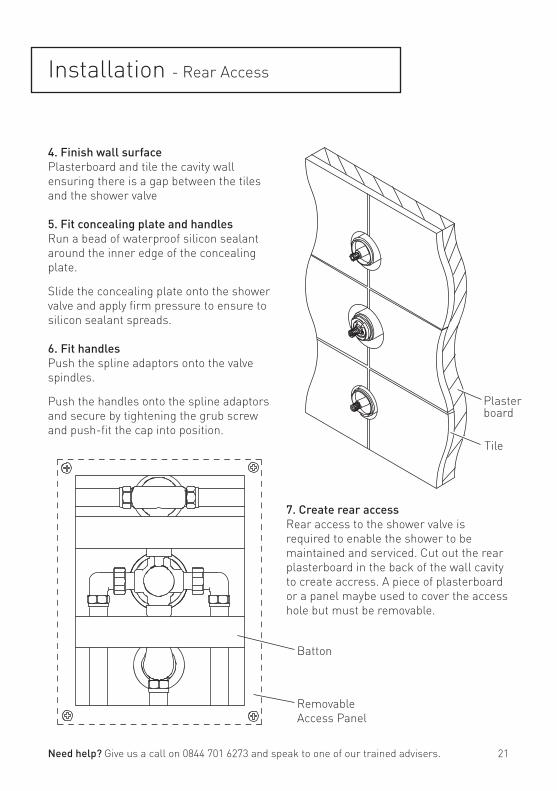
Installation - Rear Access
4. Finish wall surfacePlasterboard and tile the cavity wall ensuring there is a gap between the tiles and the shower valve
5. Fit concealing plate and handlesRun a bead of waterproof silicon sealant around the inner edge of the concealing plate.
Slide the concealing plate onto the shower valve and apply firm pressure to ensure to silicon sealant spreads.
6. Fit handlesPush the spline adaptors onto the valve spindles.
Push the handles onto the spline adaptors and secure by tightening the grub screw and push-fit the cap into position.
7. Create rear accessRear access to the shower valve is required to enable the shower to be maintained and serviced. Cut out the rear plasterboard in the back of the wall cavity to create accress. A piece of plasterboard or a panel maybe used to cover the access hole but must be removable.
Removable Access Panel
Batton
Tile
Plasterboard
Need help? Give us a call on 0844 701 6273 and speak to one of our trained advisers. 21

Installation - Wall Outlet
Fitting the Wall OutletThere are two methods of fixing the wall outlet depending on the type of wall:
a: With rear access once wall finishedFit the rubber washer to the back of the wall outlet, place the assembly through a 25-30mm hole in the wall and secure with the backnut ensuring the washer is fitted between the backnut and the wall.
Connect the wall outlet assembly to the shower valve outlet.
b: Without rear access once wall finishedFit a ‘1/2” female connection’ (not supplied) within the wall cavity and plumb in from the shower valve. Screw the wall outlet into the ‘1/2” female connection’ using a suitable thread sealant ensuring the rubber seal is fitted to the back of the wall outlet.
Note: The backnut and washer are not required.
Backnut
Washer
Wall
Rubber seal
Wall outlet
Wall
Rubber seal
Wall outlet
Female fitting
22 Need help? Give us a call on 0844 701 6273 and speak to one of our trained advisers.

Operating the Shower
Hot
1. Two outlet diverterThis outlet allows the user to divert the flow of water from one product to another.
Turn the handle one way or the other to turn the flow of water on to your chosen product.
To turn the flow of water off turn the handle back to the centre.
2. Temperature controlAdjustable temperature control.
Turn the handle clockwise for a cooler temperature.
Turn the handle anti-clockwise for a hotter temperature.
3. Single outlet stopcockAllows the user to operate a product while one outlet from the top diverter is also being used.
Turn the handle anti-clockwise to turn the flow of water on.
Turn the handle back to the centre to turn the flow of water off.
Cold
On
Off
1
2
3
Need help? Give us a call on 0844 701 6273 and speak to one of our trained advisers. 23

Maintenance
General CleaningYour fitting has a high quality finish and should be treated with care to preserve the visible surfaces. All surfaces will wear if not cleaned correctly, the only safe way to clean your product is to wipe with a soft damp cloth. Stains can be removed using washing up liquid. All bath cleaning powders and liquids will damage the surface of your fitting, even the non-scratch cleaners.
Note: Never use abrasive detergents or disinfectants or those containing alcohol, hydrochloric acid or phosphoric acid.
Bristan recommend E-cloth for cleaning all of our bathroom & kitchen products. Using just water, E-cloth gives a smear
free, deep clean by breaking up and holding dirt, which normal cloths leave behind. Order through your Bristan stockist (order code: ECLOTH).
Cartridge MaintenanceWe advise that the shower valve is regularly serviced in hard water areas to maintain the flow of water.Isolate both hot and cold water supplies to the shower valve by either:• Turning the water supply off at the mains stopcock or• Turning off the isolation valves to the shower valve.
1. Remove the temperature handle and plastic stop.
Important: Take note of the position of the plastic stop and handle - They must be refitted in the same position.
2. Unscrew the cartridge anti-clockwise and remove from the valve body.
3. Remove the piston and thermostat assembly and place into a bowl. Carefully add hot water (just off the boil) and vinegar to de-scale. Leave in the solution until the water has cooled and rinse with clean water.
4. Grease the seals with a silicon grease supplied by Bristan (part number: SP-495-0002) and carefully refit.
5. Refit the temperature stop and handle. Reset the maximum temperature.
Piston
Thermostat
Unscrewanti-clockwiseto remove
Tighten clockwiseto replace
24 Need help? Give us a call on 0844 701 6273 and speak to one of our trained advisers.

Adjusting the Temperature
Adjusting the TemperatureThe shower valve has been factory set to 42ºC with equal (balanced) hot and cold water supply pressures, with the hot water supply at 65ºC.
If your operating conditions are different from those above, the outlet water temperature may differ from the factory setting.
If required the shower valve can be re-calibrated to suit your own temperature requirements.
Set the temperature control to the maximum setting and check the
temperature of the water with a thermometer. If the temperature is not correct, re-calibrate the shower valve:
1. Remove the temperature handle but do not remove the plastic temperature stop.
2. Turn the spline clockwise to decrease the temperature and anti-clockwise to increase the temperature. Check the temperature and adjust until you achieve the required temperature.
3. Replace the temperature handle ensuring it is fitted back into the maximum position.
Temperature Stop(Do not remove)
Spline
Hotter
Colder
Need help? Give us a call on 0844 701 6273 and speak to one of our trained advisers. 25

Troubleshooting
Symptom Cause Remedy
No flow or low flow rate and / or varying temperatures.
Check showerhead, hose and filters for any blockage.
Clean as necessary, refer to Maintenance section (page 24).
Partially closed stop or service valve in water supply pipework to the shower valve.
Open stop or service valve.
Instantaneous water heater cycles on and off as the flow rate or pressure is too low.
Increase water flow rate or pressure through system. Contact the boiler manufacturer.
Head of water is below the minimum distance required.
Raise the cistern or fit a shower booster pump.
Inlet filter is partially blocked. Clean or replace, flush through pipework before refitting.
Hot or cold water being drawn off elsewhere causing pressure changes or instantaneous boiler temperature changes.
Do not use other water outlets when using the shower.
Make sure the maintained inlet pressures are nominally balanced and sufficient.
Refer to Specification (page 6).
Airlock or partial blockage of the pipework.
Flush through pipework to ensure removal of debris and any airlocks.
No hot or cold water reaching the shower valve.
Check hot and cold feeds (the valve will shut down if either the hot or cold supply fails).
Only hot or cold water from the shower valve outlet.
Partially closed stop or service valve in water supply pipework to the shower valve.
Open stop or service valve.
Inlet filter is partially blocked. Clean or replace, flush through pipework before refitting.
Inlet water supplies are reversed (hot to cold supply).
Check the connections are the correct way round. Hot on the left and cold on the right when viewed from the front. Rework pipework as necessary.
26 Need help? Give us a call on 0844 701 6273 and speak to one of our trained advisers.
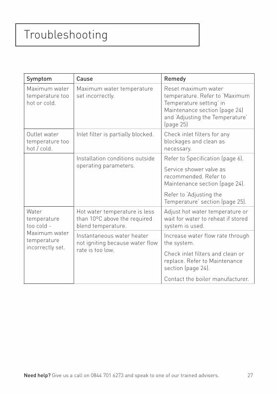
Troubleshooting
Symptom Cause Remedy
Maximum water temperature too hot or cold.
Maximum water temperature set incorrectly.
Reset maximum water temperature. Refer to ‘Maximum Temperature setting’ in Maintenance section (page 24) and ‘Adjusting the Temperature’ (page 25)
Outlet water temperature too hot / cold.
Inlet filter is partially blocked. Check inlet filters for any blockages and clean as necessary.
Installation conditions outside operating parameters.
Refer to Specification (page 6).
Service shower valve as recommended. Refer to Maintenance section (page 24).
Refer to ‘Adjusting the Temperature’ section (page 25).
Water temperature too cold - Maximum water temperature incorrectly set.
Hot water temperature is less than 10ºC above the required blend temperature.
Adjust hot water temperature or wait for water to reheat if stored system is used.
Instantaneous water heater not igniting because water flow rate is too low.
Increase water flow rate through the system.
Check inlet filters and clean or replace. Refer to Maintenance section (page 24).
Contact the boiler manufacturer.
Need help? Give us a call on 0844 701 6273 and speak to one of our trained advisers. 27

Notes
Please use this space to add any notes you or your installer may have regarding the plumbing system / installation of this product.
28 Need help? Give us a call on 0844 701 6273 and speak to one of our trained advisers.

Notes
Please use this space to add any notes you or your installer may have regarding the plumbing system / installation of this product.
Need help? Give us a call on 0844 701 6273 and speak to one of our trained advisers. 29

Guarantee
At Bristan, we want to make things as easy as possible for our customers. That’s why we design products that are easy to fit and use, and that are quality tested to make sure they won’t let you down. It’s also why we offer solid guarantees on all products, effective from the date of purchase, to give you peace of mind.
Bristan’s shower valves are covered by a 5 year guarantee. This also includes 5 years labour cover * (subject to registration)which means that, in the unlikely event that there is a problem in the first year after purchase, we’ll send one of our expert engineers to fix it.
*Labour is provided by an approved Bristan Care engineer or appointed representative. The guarantee only applies to products with a manufacturing fault. There will be a call out charge for any incidents where no fault has been found with the product, or if the issue is due to poor installation or maintenance.
Guarantee Terms and ConditionsThis guarantee is in addition to your statutory and other legal rights and is subject to the following conditions:
• The product was purchased within the United Kingdom or Republic of Ireland.
• The guarantee applies solely to the original purchaser with proof of purchase.
• The installation must allow ready access to all products for the purpose of inspection, maintenance or replacement.
• Repair under this guarantee does not extend the original expiry date. The guarantee on any replacement parts or product ends at the original expiry date.
• Any part found to be defective during the guarantee period will be replaced without charge, providing that the product has been installed in accorance with the instructions given in this guide
and used as the manufacturer intended.
The guarantee does not cover:
• Damage or defects caused by;
- General wear and tear (including special non-chrome finishes; components such as filters, seals, ‘O’ rings and washers) - Incorrect installation - Repair using non-Bristan parts - Accidental or wilful misuse - Corrosion and the use of inappropriate cleaning products - System debris including the build up of limescale (which can be controlled through regular servicing and maintenance)
• Compensation for loss of use of the product or consequential loss of any kind.
In the interests of continuous product improvement, Bristan reserves the right to alter product specifications without notice.
The Bristan Product Guarantee does not affect your statutory rights as a consumer.
30 Need help? Give us a call on 0844 701 6273 and speak to one of our trained advisers.

Guarantee
• Need help?If this product does not function correctly when first used, contact Bristan Care Customer Service on 0844 701 6273 where our expert team of advisors will be able to offer you help and advice.
• Problems during the guarantee periodIn the unlikely event that you encounter any problems with the product during the guarantee period, contact Bristan Care Customer Service on 0844 701 6273 with your proof of purchase and we will work to resolve the problem quickly.
Bristan Care Customer SupportBristan customers also benefit from the support of Bristan Care, our comprehensive customer support package which offers:
Technical support hotline(Tel: 0844 701 6273) with access to fully trained advisers who can offer installation advice, talk you through quick maintenance checks, or recommend the best course of action to fix any problems with a product.
Expert adviceFind easy to follow ‘how to’ video guides and technical FAQs online at www.bristan.com. Our guides take you step-by-step through many product installations and you can find plenty of easy guides to quick product fixes and servicing.
Spare partsWe hold thousands of spares and we keep them for discontinued products for over seven years. Spares can easily be ordered online at www.bristan.com and are dispatched the same day.
Expert plumbing engineersIf we can’t solve the problem over the ‘phone or with a spare part, then we’ll send out one of our Bristan Care engineers to take a look. Bristan Care engineers provide free support for products that are within guarantee, but are also available to service products that are out of guarantee for a small charge. For details, please call Bristan Care Customer Service on 0844 701 6273.
Need help? Give us a call on 0844 701 6273 and speak to one of our trained advisers. 31

Part Number: FI: SHC3DIV
Issue: D4
Bristan Group Ltd,Birch Coppice Business ParkDordonTamworthStaffordshireB78 1SGWeb: www.bristan.comEmail: [email protected]
A Masco Company
Useful contact details:Customer Service:0844 7016273Customer Service Email:[email protected] Service Fax:0844 7016275Reception:0844 7016274Join us on...

CAS KIT03 CStep 1 Step 2 Step 3 Step 4
Step 5
Step 6 Step 7
Slider operation
Step 8