body exterior, doors, roof & vehicle security sec a · dtc/circuit diagnosis ..... 53 p1610...
TRANSCRIPT

BODY EXTERIOR, DOORS, ROOF & VEHICLE SECURITY
C
D
E
SECTION SECA
B
SECURITY CONTROL SYSTEM
F
G
H
I
J
L
M
EC
N
O
P
CONTENTS
S
WITH INTELLIGENT KEY SYSTEM
PRECAUTION ............................................... 5
PRECAUTIONS ................................................... 5Precaution for Supplemental Restraint System (SRS) "AIR BAG" and "SEAT BELT PRE-TEN-SIONER" ...................................................................5Precaution Necessary for Steering Wheel Rota-tion after Battery Disconnect .....................................5Precaution for Procedure without Cowl Top Cover ......6
SYSTEM DESCRIPTION .............................. 7
COMPONENT PARTS ........................................ 7Component Parts Location ........................................7Component Description .............................................8A/T Shift Selector (Detention Switch) ........................8BCM ..........................................................................8ECM ..........................................................................9IPDM E/R ..................................................................9NATS Antenna Amp. .................................................9TCM ..........................................................................9Combination Meter ....................................................9Door Switch ...............................................................9Hood Switch ..............................................................9Inside Key Antenna ...................................................9Intelligent Key ............................................................9Push-button Ignition Switch .....................................10Remote Keyless Entry Receiver .............................10Security Indicator Lamp ..........................................10Starter Control Relay ...............................................10Starter Relay ...........................................................10Steering Lock Relay ................................................10Steering Lock Unit ...................................................10Stop Lamp Switch ...................................................10Transmission Range Switch ....................................10Vehicle Information Display .....................................11
SYSTEM .............................................................12
INTELLIGENT KEY SYSTEM/ENGINE START FUNCTION .................................................................12
INTELLIGENT KEY SYSTEM/ENGINE START FUNCTION : System Diagram ................................12INTELLIGENT KEY SYSTEM/ENGINE START FUNCTION : System Description ............................12
INFINITI VEHICLE IMMOBILIZER SYSTEM-NATS ....14INFINITI VEHICLE IMMOBILIZER SYSTEM-NATS : System Diagram .........................................15INFINITI VEHICLE IMMOBILIZER SYSTEM-NATS : System Description .....................................15
VEHICLE SECURITY SYSTEM .................................17VEHICLE SECURITY SYSTEM : System Dia-gram ........................................................................17VEHICLE SECURITY SYSTEM : System Descrip-tion ...........................................................................18
DIAGNOSIS SYSTEM (BCM) ...........................21
COMMON ITEM .........................................................21COMMON ITEM : CONSULT-III Function (BCM - COMMON ITEM) .....................................................21
INTELLIGENT KEY ....................................................22INTELLIGENT KEY : CONSULT-III Function (BCM - INTELLIGENT KEY) ....................................22
THEFT ALM ...............................................................26THEFT ALM : CONSULT-III Function (BCM - THEFT) ....................................................................26
IMMU ..........................................................................27IMMU : CONSULT-III Function (BCM - IMMU) ........27
DIAGNOSIS SYSTEM (IPDM E/R) ...................28CONSULT-III Function (IPDM E/R) .........................28
ECU DIAGNOSIS INFORMATION ..............30
ECM, IPDM E/R, BCM .......................................30List of ECU Reference .............................................30
SEC-1Revision: 2010 May 2011 QX56

WIRING DIAGRAM ..................................... 31
SECURITY CONTROL SYSTEM ....................... 31Wiring Diagram ....................................................... 31
BASIC INSPECTION ................................... 48
DIAGNOSIS AND REPAIR WORK FLOW ........ 48Work Flow ............................................................... 48
ADDITIONAL SERVICE WHEN REPLACING CONTROL UNIT ................................................ 51
ECM ........................................................................... 51ECM : Description ................................................... 51ECM : Work Procedure ........................................... 51
BCM ........................................................................... 51BCM : Description ................................................... 51BCM : Work Procedure ........................................... 51
DTC/CIRCUIT DIAGNOSIS ......................... 53
P1610 LOCK MODE .......................................... 53Description .............................................................. 53DTC Logic ............................................................... 53Diagnosis Procedure .............................................. 53
P1611 ID DISCORD, IMMU-ECM ...................... 54DTC Logic ............................................................... 54Diagnosis Procedure .............................................. 54
P1612 CHAIN OF ECM-IMMU ........................... 55DTC Logic ............................................................... 55Diagnosis Procedure .............................................. 55
P1614 CHAIN OF IMMU-KEY ........................... 56DTC Logic ............................................................... 56Diagnosis Procedure .............................................. 56
B2192 ID DISCORD, IMMU-ECM ...................... 60DTC Logic ............................................................... 60Diagnosis Procedure .............................................. 60
B2193 CHAIN OF ECM-IMMU ........................... 61DTC Logic ............................................................... 61Diagnosis Procedure .............................................. 61
B2195 ANTI-SCANNING ................................... 62DTC Logic ............................................................... 62Diagnosis Procedure .............................................. 62
B2196 DONGLE UNIT ....................................... 63Description .............................................................. 63DTC Logic ............................................................... 63Diagnosis Procedure .............................................. 63
B2198 NATS ANTENNA AMP. ......................... 65DTC Logic ............................................................... 65Diagnosis Procedure .............................................. 65
B2013 STEERING LOCK UNIT ......................... 69DTC Logic ............................................................... 69
Diagnosis Procedure ............................................... 69
B2014 CHAIN OF STRG-IMMU ........................ 70DTC Logic ............................................................... 70Diagnosis Procedure ............................................... 70
B2555 STOP LAMP ........................................... 73DTC Logic ............................................................... 73Diagnosis Procedure ............................................... 73Component Inspection ............................................ 74
B2556 PUSH-BUTTON IGNITION SWITCH ..... 76DTC Logic ............................................................... 76Diagnosis Procedure ............................................... 76Component Inspection ............................................ 77
B2557 VEHICLE SPEED ................................... 78DTC Logic ............................................................... 78Diagnosis Procedure ............................................... 78
B2601 SHIFT POSITION ................................... 79DTC Logic ............................................................... 79Diagnosis Procedure ............................................... 79Component Inspection ............................................ 81
B2602 SHIFT POSITION ................................... 82DTC Logic ............................................................... 82Diagnosis Procedure ............................................... 82Component Inspection ............................................ 83
B2603 SHIFT POSITION ................................... 85DTC Logic ............................................................... 85Diagnosis Procedure ............................................... 85Component Inspection ............................................ 87
B2604 SHIFT POSITION ................................... 89DTC Logic ............................................................... 89Diagnosis Procedure ............................................... 89
B2605 SHIFT POSITION ................................... 91DTC Logic ............................................................... 91Diagnosis Procedure ............................................... 91
B2608 STARTER RELAY ................................. 93DTC Logic ............................................................... 93Diagnosis Procedure ............................................... 93
B2609 STEERING STATUS .............................. 95DTC Logic ............................................................... 95Diagnosis Procedure ............................................... 95
B260B STEERING LOCK UNIT ........................ 98DTC Logic ............................................................... 98Diagnosis Procedure ............................................... 98
B260C STEERING LOCK UNIT ........................ 99DTC Logic ............................................................... 99Diagnosis Procedure ............................................... 99
B260D STEERING LOCK UNIT .......................100DTC Logic ............................................................. 100Diagnosis Procedure ............................................. 100
SEC-2Revision: 2010 May 2011 QX56

C
D
E
F
G
H
I
J
L
M
A
B
EC
N
O
P
S
B260F ENGINE STATUS ................................. 101Description ............................................................ 101DTC Logic ............................................................. 101Diagnosis Procedure ............................................. 101
B2612 STEERING STATUS ............................. 102DTC Logic ............................................................. 102Diagnosis Procedure ............................................. 102
B2619 BCM ...................................................... 105DTC Logic ............................................................. 105Diagnosis Procedure ............................................. 105
B26E9 STEERING STATUS ............................ 106DTC Logic ............................................................. 106Diagnosis Procedure ............................................. 106
B26EF STEERING LOCK RELAY ................... 107DTC Logic ............................................................. 107Diagnosis Procedure ............................................. 107
B26F0 STEERING LOCK RELAY ................... 109DTC Logic ............................................................. 109Diagnosis Procedure ............................................. 109
B26F3 STARTER CONTROL RELAY ............. 111DTC Logic ............................................................. 111Diagnosis Procedure ............................................. 111
B26F4 STARTER CONTROL RELAY ............. 112DTC Logic ............................................................. 112Diagnosis Procedure ............................................. 112
B26F5 STEERING LOCK STATUS SWITCH ..113DTC Logic ............................................................. 113Diagnosis Procedure ............................................. 113
B26F7 BCM ...................................................... 116DTC Logic ............................................................. 116Diagnosis Procedure ............................................. 116
B26F8 BCM ...................................................... 117DTC Logic ............................................................. 117Diagnosis Procedure ............................................. 117
B26F9 CRANKING REQUEST CIRCUIT ......... 118DTC Logic ............................................................. 118Diagnosis Procedure ............................................. 118
B26FA CRANKING REQUEST CIRCUIT ........ 120DTC Logic ............................................................. 120Diagnosis Procedure ............................................. 120
B26FC KEY REGISTRATION .......................... 122DTC Logic ............................................................. 122Diagnosis Procedure ............................................. 122
B209F CRANKING REQUEST CIRCUIT ......... 123DTC Logic ............................................................. 123Diagnosis Procedure ............................................. 123
B20A0 CRANKING REQUEST CIRCUIT ....... 125DTC Logic ..............................................................125Diagnosis Procedure .............................................125
B2108 STEERING LOCK RELAY .................. 127DTC Logic ..............................................................127Diagnosis Procedure .............................................127
B2109 STEERING LOCK RELAY .................. 128DTC Logic ..............................................................128Diagnosis Procedure .............................................128
B210A STEERING LOCK UNIT ...................... 129DTC Logic ..............................................................129Diagnosis Procedure .............................................129
B210B STARTER CONTROL RELAY ............ 131DTC Logic ..............................................................131Diagnosis Procedure .............................................131
B210C STARTER CONTROL RELAY ............ 132DTC Logic ..............................................................132Diagnosis Procedure .............................................132
B210D STARTER RELAY .............................. 133DTC Logic ..............................................................133Diagnosis Procedure .............................................133
B210E STARTER RELAY ............................... 134DTC Logic ..............................................................134Diagnosis Procedure .............................................134
B210F SHIFT POSITION/CLUTCH INTER-LOCK SWITCH ............................................... 136
DTC Logic ..............................................................136Diagnosis Procedure .............................................136
B2110 SHIFT POSITION/CLUTCH INTER-LOCK SWITCH ............................................... 138
DTC Logic ..............................................................138Diagnosis Procedure .............................................138
HEADLAMP FUNCTION ................................. 140Component Function Check ..................................140Diagnosis Procedure .............................................140
HOOD SWITCH ............................................... 141Component Function Check ................................141Diagnosis Procedure ............................................141Component Inspection ...........................................142
HORN FUNCTION ........................................... 143Component Function Check ................................143Diagnosis Procedure ............................................143Component Inspection ...........................................145
SECURITY INDICATOR LAMP ...................... 146Component Function Check ................................146Diagnosis Procedure .............................................146
SYMPTOM DIAGNOSIS ............................ 148
SEC-3Revision: 2010 May 2011 QX56

ENGINE DOES NOT START WHEN INTELLI-GENT KEY IS INSIDE OF VEHICLE ............... 148
Description .............................................................148Diagnosis Procedure .............................................148
STEERING DOES NOT LOCK ........................ 149Description .............................................................149Diagnosis Procedure .............................................149
SECURITY INDICATOR LAMP DOES NOT TURN ON OR BLINK ....................................... 150
Description .............................................................150Diagnosis Procedure .............................................150
VEHICLE SECURITY SYSTEM CANNOT BE SET .................................................................. 151
INTELLIGENT KEY ..................................................151INTELLIGENT KEY : Description ..........................151INTELLIGENT KEY : Diagnosis Procedure ...........151
DOOR REQUEST SWITCH .....................................151DOOR REQUEST SWITCH : Description .............151
DOOR REQUEST SWITCH : Diagnosis Proce-dure ....................................................................... 151
DOOR KEY CYLINDER .......................................... 152DOOR KEY CYLINDER : Description ................... 152DOOR KEY CYLINDER : Diagnosis Procedure ... 152
VEHICLE SECURITY ALARM DOES NOT ACTIVATE ........................................................153
Description ............................................................ 153Diagnosis Procedure ............................................. 153
PANIC ALARM FUNCTION DOES NOT OP-ERATE ..............................................................154
Description ............................................................ 154Diagnosis Procedure ............................................. 154
REMOVAL AND INSTALLATION .............155
NATS ANTENNA AMP. ....................................155Removal and Installation ....................................... 155
PUSH-BUTTON IGNITION SWITCH ................156Exploded View ...................................................... 156Removal and Installation ....................................... 156
SEC-4Revision: 2010 May 2011 QX56

PRECAUTIONS[WITH INTELLIGENT KEY SYSTEM]
C
D
E
F
G
H
I
J
L
M
A
B
EC
N
O
P
< PRECAUTION >
S
PRECAUTIONPRECAUTIONS
Precaution for Supplemental Restraint System (SRS) "AIR BAG" and "SEAT BELT PRE-TENSIONER" INFOID:0000000006226148
The Supplemental Restraint System such as “AIR BAG” and “SEAT BELT PRE-TENSIONER”, used alongwith a front seat belt, helps to reduce the risk or severity of injury to the driver and front passenger for certaintypes of collision. This system includes seat belt switch inputs and dual stage front air bag modules. The SRSsystem uses the seat belt switches to determine the front air bag deployment, and may only deploy one frontair bag, depending on the severity of a collision and whether the front occupants are belted or unbelted.Information necessary to service the system safely is included in the “SRS AIR BAG” and “SEAT BELT” of thisService Manual.WARNING:• To avoid rendering the SRS inoperative, which could increase the risk of personal injury or death in
the event of a collision that would result in air bag inflation, all maintenance must be performed byan authorized NISSAN/INFINITI dealer.
• Improper maintenance, including incorrect removal and installation of the SRS, can lead to personalinjury caused by unintentional activation of the system. For removal of Spiral Cable and Air BagModule, see the “SRS AIR BAG”.
• Do not use electrical test equipment on any circuit related to the SRS unless instructed to in thisService Manual. SRS wiring harnesses can be identified by yellow and/or orange harnesses or har-ness connectors.
PRECAUTIONS WHEN USING POWER TOOLS (AIR OR ELECTRIC) AND HAMMERSWARNING:• When working near the Air Bag Diagnosis Sensor Unit or other Air Bag System sensors with the
ignition ON or engine running, DO NOT use air or electric power tools or strike near the sensor(s)with a hammer. Heavy vibration could activate the sensor(s) and deploy the air bag(s), possiblycausing serious injury.
• When using air or electric power tools or hammers, always switch the ignition OFF, disconnect thebattery, and wait at least 3 minutes before performing any service.
Precaution Necessary for Steering Wheel Rotation after Battery DisconnectINFOID:0000000006226149
NOTE:• Before removing and installing any control units, first turn the push-button ignition switch to the LOCK posi-
tion, then disconnect both battery cables.• After finishing work, confirm that all control unit connectors are connected properly, then re-connect both
battery cables.• Always use CONSULT-III to perform self-diagnosis as a part of each function inspection after finishing work.
If a DTC is detected, perform trouble diagnosis according to self-diagnosis results.For vehicle with steering lock unit, if the battery is disconnected or discharged, the steering wheel will lock andcannot be turned.If turning the steering wheel is required with the battery disconnected or discharged, follow the operation pro-cedure below before starting the repair operation.
OPERATION PROCEDURE1. Connect both battery cables.
NOTE:Supply power using jumper cables if battery is discharged.
2. Turn the push-button ignition switch to ACC position.(At this time, the steering lock will be released.)
3. Disconnect both battery cables. The steering lock will remain released with both battery cables discon-nected and the steering wheel can be turned.
4. Perform the necessary repair operation.
SEC-5Revision: 2010 May 2011 QX56

[WITH INTELLIGENT KEY SYSTEM]PRECAUTIONS
< PRECAUTION >5. When the repair work is completed, re-connect both battery cables. With the brake pedal released, turn
the push-button ignition switch from ACC position to ON position, then to LOCK position. (The steeringwheel will lock when the push-button ignition switch is turned to LOCK position.)
6. Perform self-diagnosis check of all control units using CONSULT-III.
Precaution for Procedure without Cowl Top Cover INFOID:0000000006226150
When performing the procedure after removing cowl top cover, coverthe lower end of windshield with urethane, etc.
PIIB3706J
SEC-6Revision: 2010 May 2011 QX56

COMPONENT PARTS[WITH INTELLIGENT KEY SYSTEM]
C
D
E
F
G
H
I
J
L
M
A
B
EC
N
O
P
< SYSTEM DESCRIPTION >
S
SYSTEM DESCRIPTIONCOMPONENT PARTS
Component Parts Location INFOID:0000000006226151
1. Inside key antenna (console)Refer to DLK-11, "DOOR LOCK SYSTEM : Component Parts Location".
2. A/T assemblyRefer to TM-10, "A/T CONTROL SYSTEM : Component Parts Loca-tion".
3. Push-button ignition switch
4. NATS antenna amp. 5. Inside key antenna (instrument cen-ter)Refer to DLK-11, "DOOR LOCK SYSTEM : Component Parts Location".
6. IPDM E/RRefer to PCS-4, "Component Parts Location".
7. ECMRefer to EC-16, "Component Parts Location").
8. Horn 9. ABS actuator and electric unit (con-trol unit)Refer to BRC-10, "Component Parts Location".
10. Stop lamp switchRefer to EC-16, "Component Parts Location".
11. BCMRefer to BCS-4, "BODY CONTROL SYSTEM : Component Parts Loca-tion".
12. Combination meterRefer to MWI-6, "METER SYSTEM : Component Parts Location".
JMKIA5243ZZ
SEC-7Revision: 2010 May 2011 QX56

[WITH INTELLIGENT KEY SYSTEM]COMPONENT PARTS
< SYSTEM DESCRIPTION >
Component Description INFOID:0000000006226152
A/T Shift Selector (Detention Switch) INFOID:0000000006226153
Detention switch detects that A/T shift selector is in the P position, and then transmits the signal to BCM andIPDM E/R.BCM confirms the A/T shift selector position with the following 5 signals.• P position signal from A/T shift selector (detention switch)• P/N position signal from TCM• P position signal from IPDM E/R (CAN)• P/N position signal from IPDM E/R (CAN)• P/N position signal from TCM (CAN)IPDM E/R confirms the A/T shift selector position with the following 3 signals.• P position signal from A/T shift selector (detention switch)• P/N position signal from TCM• P/N position signal from BCM (CAN)
BCM INFOID:0000000006226154
BCM controls INTELLIGENT KEY SYSTEM (ENGINE START FUNCTION), INFINITI VEHICLE IMMOBI-LIZER SYSTEM-NATS [IVIS (NATS)], and VEHICLE SECURITY SYSTEM.BCM performs the ID verification between BCM and Intelligent Key when the Intelligent Key is carried into thedetection area of inside key antenna, and push-button ignition switch is pressed. If the ID verification result isOK, push-button ignition switch operation is available.
13. Front door switch (driver side)Refer to DLK-11, "DOOR LOCK SYSTEM : Component Parts Location".
14. Remote keyless entry receiverRefer to DLK-11, "DOOR LOCK SYSTEM : Component Parts Location".
15. Inside key antenna (luggage room)Refer to DLK-11, "DOOR LOCK SYSTEM : Component Parts Location".
A. Behind push-button ignition switch
Component Reference
A/T shift selector (detention switch) SEC-8
BCM SEC-8
ECM SEC-9
IPDM E/R SEC-9
NATS antenna amp. SEC-9
TCM SEC-9
Combination meter SEC-9
Door switch SEC-9
Hood switch SEC-9
Inside key antenna SEC-9
Intelligent Key SEC-9
Push-button ignition switch SEC-10
Remote keyless entry receiver SEC-10
Security indicator lamp SEC-10
Starter control relay SEC-10
Starter relay SEC-10
Steering lock relay SEC-10
Steering lock unit SEC-10
Stop lamp switch SEC-10
Transmission range switch SEC-10
Vehicle information display SEC-11
SEC-8Revision: 2010 May 2011 QX56

COMPONENT PARTS[WITH INTELLIGENT KEY SYSTEM]
C
D
E
F
G
H
I
J
L
M
A
B
EC
N
O
P
< SYSTEM DESCRIPTION >
S
Then, when the power supply position is turned ON, BCM performs ID verification between BCM and ECM. Ifthe ID verification result is OK, ECM can start engine.
ECM INFOID:0000000006226155
ECM controls the engine.When power supply position is turned ON, BCM starts communication with ECM and performs the ID verifica-tion between BCM and ECM.If the verification result is OK, the engine can start. If the verification result is NG, the engine can not start.
IPDM E/R INFOID:0000000006226156
IPDM E/R has steering lock relay, starter relay and starter control relay inside. Steering lock relay is used forthe steering lock/unlock function. Starter relay and starter control relay are used for the engine starting func-tion. IPDM E/R controls these relays while communicating with BCM.
NATS Antenna Amp. INFOID:0000000006226157
The ID verification is performed between BCM and transponder in Intelligent Key via NATS antenna amp.when Intelligent Key backside is contacted to push-button ignition switch in case that Intelligent Key battery isdischarged. If the ID verification result is OK, the release of steering lock and the operation of starting engineis available.
TCM INFOID:0000000006226158
TCM transmits the shift position signal (P/N position) to BCM and IPDM E/R. And further, TCM transmits theshift position signal (P/N position) to BCM via CAN communication.BCM confirms the A/T shift selector position with the following 5 signals.• P position signal from A/T shift selector (detention switch)• P/N position signal from TCM• P position signal from IPDM E/R (CAN)• P/N position signal from IPDM E/R (CAN)• P/N position signal from TCM (CAN)IPDM E/R confirms the A/T shift selector position with the following 3 signals.• P position signal from A/T shift selector (detention switch)• P/N position signal from TCM• P/N position signal from BCM (CAN)
Combination Meter INFOID:0000000006226159
Combination meter transmits the vehicle speed signal to BCM via CAN communication.BCM also receives the vehicle speed signal from ABS actuator and electric unit (control unit) via CAN commu-nication. BCM compares both signals to detect the vehicle speed.
Door Switch INFOID:0000000006226160
Door switch detects door open/close condition and then transmits ON/OFF signal to BCM.
Hood Switch INFOID:0000000006226161
Hood switch detects that hood is open, and then transmits the signal to IPDM E/R. IPDM E/R transmits hoodswitch signal to BCM via CAN communication.
Inside Key Antenna INFOID:0000000006226162
Inside key antenna detects whether Intelligent Key is inside the vehicle, and transmits the signal to BCM.Three inside key antennas are installed in the instrument center, console and luggage room.
Intelligent Key INFOID:0000000006226163
Each Intelligent key has an individual electronic ID, and transmits the ID signal by request from BCM.Carrying the Intelligent Key whose ID is registered in BCM, the driver can performs door lock/unlock operationand push-button ignition switch operation.
SEC-9Revision: 2010 May 2011 QX56

[WITH INTELLIGENT KEY SYSTEM]COMPONENT PARTS
< SYSTEM DESCRIPTION >
Push-button Ignition Switch INFOID:0000000006226165
Push-button ignition switch detects that push-button is pressed, and then transmits the signal to BCM. BCMchanges the power supply position with the operation of push-button ignition switch. BCM maintains the powersupply position status while push-button is not operated.
Remote Keyless Entry Receiver INFOID:0000000006226166
Remote keyless entry receiver receives each button operation signal and electronic key ID signal from Intelli-gent Key, and then transmits the signal to BCM.
Security Indicator Lamp INFOID:0000000006226167
Security indicator lamp is located on combination meter.Security indicator lamp blinks when power supply position is any position other than ON to warn that INFINITIVEHICLE IMMOBILIZER SYSTEM-NATS [IVIS (NATS)] is on board.
Starter Control Relay INFOID:0000000006226170
Engine starting system functions by controlling both starter relay and starter control relay.Both relays are integrated in IPDM E/R. Starter relay is controlled by BCM, and starter control relay is con-trolled by IPDM E/R on request from BCM.IPDM E/R transmits starter relay and starter control relay status signal to BCM via CAN communication.
Starter Relay INFOID:0000000006226171
Engine starting system functions by controlling both starter relay and starter control relay.Both relays are integrated in IPDM E/R. Starter relay is controlled by BCM, and starter control relay is con-trolled by IPDM E/R on request from BCM.IPDM E/R transmits starter relay and starter control relay status signal to BCM via CAN communication.
Steering Lock Relay INFOID:0000000006226172
Steering lock relay is integrated in IPDM E/R, and supplies power source to steering lock unit.When IPDM E/R receives the steering lock relay ON request signal from BCM, IPDM E/R turns ON steeringlock relay and then transmits the steering lock relay condition signal to BCM.
Steering Lock Unit INFOID:0000000006226173
Steering lock unit performs steering lock/unlock operation on request from BCM, and power source is suppliedfrom steering lock relay integrated in IPDM E/R.When push-button ignition switch is pressed while the Intelligent Key is inside the vehicle, BCM performs theID verification with steering lock unit. Steering lock unit releases the steering lock based on the result of the IDverification.Steering lock unit has 2 switches (steering lock status switch and steering unlock status switch) inside. BCMjudges the steering lock/unlock condition by comparing these switch signals and steering lock unit status sig-nal transmitted from IPDM E/R via CAN communication.
Stop Lamp Switch INFOID:0000000006226174
Stop lamp switch detects that brake pedal is depressed, and then transmits the signal to BCM.
Transmission Range Switch INFOID:0000000006226175
Transmission range switch is integrated in A/T assembly, and detects the A/T shift selector position.TCM receives the transmission range switch signal and then transmits the P/N position signal to BCM andIPDM E/R.BCM confirms the A/T shift selector position with the following 5 signals.• P position signal from A/T shift selector (detention switch)• P/N position signal from TCM• P position signal from IPDM E/R (CAN)• P/N position signal from IPDM E/R (CAN)• P/N position signal from TCM (CAN)IPDM E/R confirms the A/T shift selector position with the following 3 signals.
SEC-10Revision: 2010 May 2011 QX56

COMPONENT PARTS[WITH INTELLIGENT KEY SYSTEM]
C
D
E
F
G
H
I
J
L
M
A
B
EC
N
O
P
< SYSTEM DESCRIPTION >
S
• P position signal from A/T shift selector (detention switch)• P/N position signal from TCM• P/N position signal from BCM (CAN)
Vehicle Information Display INFOID:0000000006226176
Vehicle information display is integrated in combination meter.Various information and warnings regarding to the Intelligent Key System are displayed.
SEC-11Revision: 2010 May 2011 QX56

[WITH INTELLIGENT KEY SYSTEM]SYSTEM
< SYSTEM DESCRIPTION >
SYSTEMINTELLIGENT KEY SYSTEM/ENGINE START FUNCTION
INTELLIGENT KEY SYSTEM/ENGINE START FUNCTION : System DiagramINFOID:0000000006226178
INTELLIGENT KEY SYSTEM/ENGINE START FUNCTION : System DescriptionINFOID:0000000006226179
SYSTEM DESCRIPTION • The engine start function of Intelligent Key system makes it possible to start and stop the engine without
using the key, based on the electronic ID verification. The electronic ID verification is performed betweenBCM and Intelligent Key when the push-button ignition switch is pressed while the Intelligent Key is withinthe detection area of inside key antenna.NOTE:The driver should carry the Intelligent Key at all times.
• Intelligent Key has 2 IDs [Intelligent Key ID and IVIS (NATS) ID]. It can perform the door lock/unlock opera-tion and the push-button ignition switch operation when the registered Intelligent Key is carried.
• When Intelligent Key battery is discharged, engine can be started by operating push-button ignition switchafter contacting Intelligent Key backside to push-button ignition switch. At that time, the IVIS (NATS) ID veri-fication is performed.
• If the ID is successfully verified, when push-button ignition switch is pressed, steering lock is released andthe engine can be started.
JMKIA5239GB
SEC-12Revision: 2010 May 2011 QX56

SYSTEM[WITH INTELLIGENT KEY SYSTEM]
C
D
E
F
G
H
I
J
L
M
A
B
EC
N
O
P
< SYSTEM DESCRIPTION >
S
• Up to 4 Intelligent Keys can be registered (Including the standard Intelligent Key) upon request from the cus-tomer.NOTE:Refer to DLK-18, "INTELLIGENT KEY SYSTEM : System Description" for any functions other than enginestart function of Intelligent Key system.
PRECAUTIONS FOR INTELLIGENT KEY SYSTEMThe transponder [the chip for IVIS (NATS) ID verification] is integrated into the Intelligent Key. (For theconventional models, it is integrated into the mechanical key.) Therefore, ID verification cannot be per-formed by mechanical key only.In that case, the IVIS (NATS) ID verification can be performed when Intelligent Key backside is con-tacted to push-button ignition switch. If verification result is OK, engine can be started.
OPERATION WHEN INTELLIGENT KEY IS CARRIED1. When the push-button ignition switch is pressed, the BCM activates the inside key antenna and transmits
the request signal to the Intelligent Key.2. The Intelligent Key receives the request signal and transmits the Intelligent Key ID signal to the BCM.3. BCM receives the Intelligent Key ID signal via remote keyless entry receiver and verifies it with the regis-
tered ID.4. BCM transmits the unlock signal to steering lock unit and IPDM E/R if the verification results are OK.5. IPDM E/R turns the steering lock relay ON and supplies power supply to the steering lock unit.6. The steering lock releases.7. BCM transmits the power supply stop signal to IPDM E/R when detecting that the steering lock is in the
unlock condition.8. IPDM E/R turns the steering lock relay OFF and stops power supply to the steering lock unit.9. BCM turns ACC relay ON and transmits the ignition power supply ON signal to IPDM E/R.10. IPDM E/R turns the ignition relay ON and starts the ignition power supply.11. BCM detects that the selector lever position and brake pedal operating condition.12. BCM transmits the starter request signal to IPDM E/R and turns the starter relay in IPDM E/R ON if BCM
judges that the engine start condition* is satisfied.13. IPDM E/R turns the starter control relay ON when receiving the starter request signal.14. Power supply is supplied through the starter relay and the starter control relay to operate the starter motor.
CAUTION:If a malfunction is detected in the Intelligent Key system, the “KEY” warning lamp in the combina-tion meter illuminates. At that time, the engine cannot be started.
15. When BCM receives feedback signal from ECM indicating that the engine is started, the BCM transmits astop signal to IPDM E/R and stops cranking by turning OFF the starter motor relay. (If engine start isunsuccessful, cranking stops automatically within 5 seconds.)CAUTION:When the Intelligent Key is carried outside of the vehicle (inside key antenna detection area) whilethe power supply is in the ACC or ON position, even if the engine start condition* is satisfied, theengine cannot be started.
*: For the engine start condition, refer to “POWER SUPPLY POSITION CHANGE TABLE BY PUSH-BUTTONIGNITION SWITCH OPERATION”.
OPERATION RANGEEngine can be started when Intelligent Key is inside the vehicle. However, sometimes engine may not startwhen Intelligent Key is on instrument panel or in glove box.
ENGINE START OPERATION WHEN INTELLIGENT KEY IS CONTACTED TO PUSH-BUTTON IG-NITION SWITCHWhen Intelligent Key battery is discharged, the IVIS (NATS) ID verification between transponder in IntelligentKey and BCM is performed when Intelligent Key backside is contacted to push-button ignition switch. If theverification result is OK, engine can be started.
STEERING LOCK OPERATIONSteering is locked by steering lock unit when any of the following conditions are met.
SEC-13Revision: 2010 May 2011 QX56
[WITH INTELLIGENT KEY SYSTEM]SYSTEM
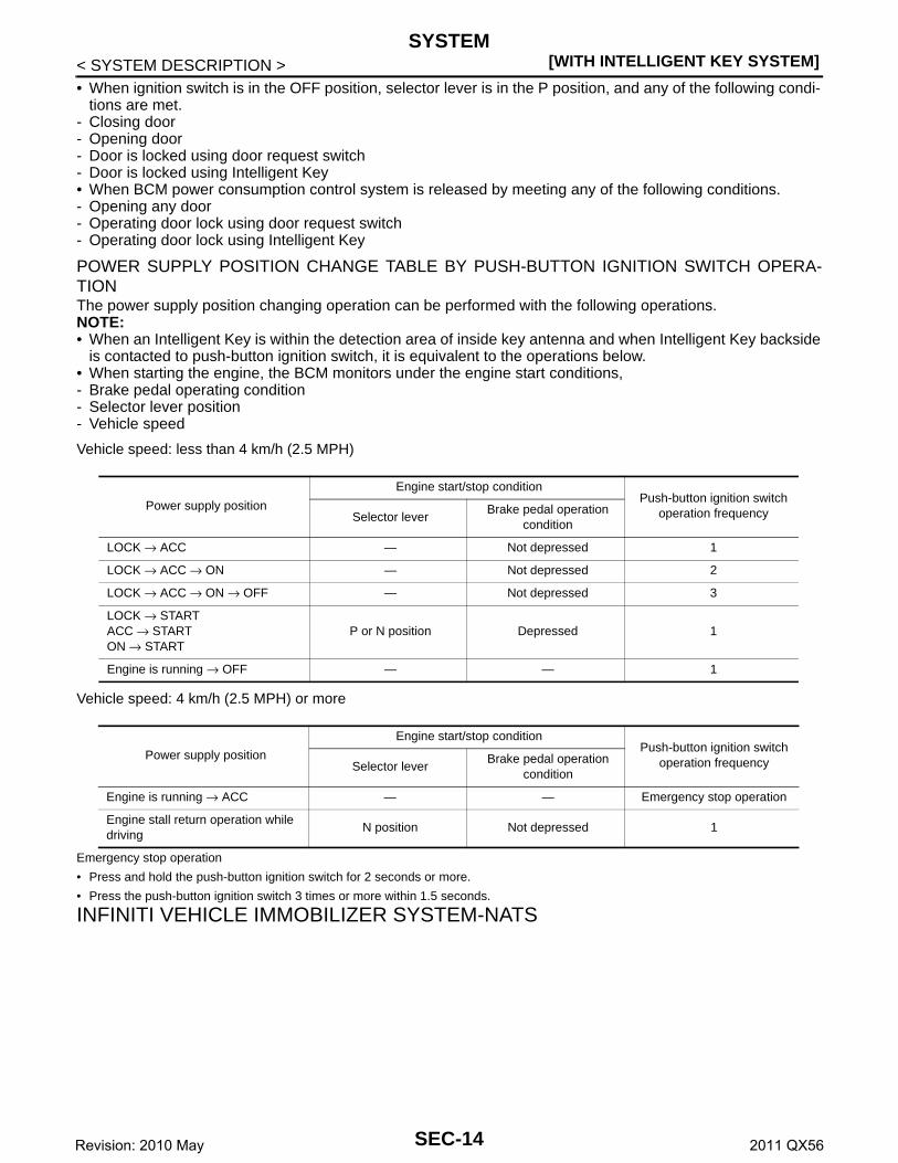
< SYSTEM DESCRIPTION >• When ignition switch is in the OFF position, selector lever is in the P position, and any of the following condi-
tions are met.- Closing door- Opening door- Door is locked using door request switch- Door is locked using Intelligent Key• When BCM power consumption control system is released by meeting any of the following conditions.- Opening any door- Operating door lock using door request switch- Operating door lock using Intelligent Key
POWER SUPPLY POSITION CHANGE TABLE BY PUSH-BUTTON IGNITION SWITCH OPERA-TIONThe power supply position changing operation can be performed with the following operations.NOTE:• When an Intelligent Key is within the detection area of inside key antenna and when Intelligent Key backside
is contacted to push-button ignition switch, it is equivalent to the operations below.• When starting the engine, the BCM monitors under the engine start conditions,- Brake pedal operating condition- Selector lever position- Vehicle speed
Vehicle speed: less than 4 km/h (2.5 MPH)
Vehicle speed: 4 km/h (2.5 MPH) or more
Emergency stop operation
• Press and hold the push-button ignition switch for 2 seconds or more.
• Press the push-button ignition switch 3 times or more within 1.5 seconds.
INFINITI VEHICLE IMMOBILIZER SYSTEM-NATS
Power supply position
Engine start/stop conditionPush-button ignition switch
operation frequencySelector leverBrake pedal operation
condition
LOCK → ACC — Not depressed 1
LOCK → ACC → ON — Not depressed 2
LOCK → ACC → ON → OFF — Not depressed 3
LOCK → STARTACC → STARTON → START
P or N position Depressed 1
Engine is running → OFF — — 1
Power supply position
Engine start/stop conditionPush-button ignition switch
operation frequencySelector leverBrake pedal operation
condition
Engine is running → ACC — — Emergency stop operation
Engine stall return operation while driving
N position Not depressed 1
SEC-14Revision: 2010 May 2011 QX56

SYSTEM[WITH INTELLIGENT KEY SYSTEM]
C
D
E
F
G
H
I
J
L
M
A
B
EC
N
O
P
< SYSTEM DESCRIPTION >
S
INFINITI VEHICLE IMMOBILIZER SYSTEM-NATS : System Diagram INFOID:0000000006226180
INFINITI VEHICLE IMMOBILIZER SYSTEM-NATS : System Description INFOID:0000000006226181
SYSTEM DESCRIPTION• The INFINITI VEHICLE IMMOBILIZER SYSTEM-NATS [IVIS (NATS)] prevents the engine from being
started by Intelligent Key whose ID is not registered to the vehicle (BCM). It has higher protection againstauto theft involving the duplication of mechanical keys.
• The ignition key integrated in the Intelligent Key cannot start the engine. When the Intelligent Key battery isdischarged, the IVIS (NATS) ID verification is performed between the transponder integrated with IntelligentKey and BCM via NATS antenna amp. when the Intelligent Key backside is contacted to push-button ignitionswitch. If the verification results are OK, the engine start operation can be performed by the push-button igni-tion switch operation.
• Locate the security indicator lamp and apply the anti-theft system equipment sticker that warns that the IVIS(NATS) is on board the model.
• Security indicator lamp always blinks when the power supply position is any position other than ON.• Up to 4 Intelligent Keys can be registered (including the standard ignition key) upon request from the owner.• Specified registration is required when replacing ECM, BCM or Intelligent Key. For the registration proce-
dures, refer to CONSULT-III Operation Manual NATS-IVIS/NVIS.• Possible symptom of IVIS (NATS) malfunction is “Engine cannot start”. The engine can not be started
because of other than IVIS (NATS) malfunction, so start the trouble diagnosis according to SEC-48, "WorkFlow".
• If ECM other than genuine part is installed, the engine cannot be started. For ECM replacement procedure,refer to EC-143, "Work Procedure".
JMKIA5734GB
SEC-15Revision: 2010 May 2011 QX56

[WITH INTELLIGENT KEY SYSTEM]SYSTEM
< SYSTEM DESCRIPTION >
PRECAUTIONS FOR KEY REGISTRATION• The ID registration is a procedure that erases the current IVIS (NATS) ID once, and then reregisters a new
ID. Therefore before starting the registration operation, collect all registered Intelligent Keys from the cus-tomer.
• When registering the Intelligent Key, perform only one procedure to simultaneously register both ID [IVIS(NATS) ID and Intelligent Key ID].
SECURITY INDICATOR LAMP• Warns that the vehicle is equipped with IVIS (NATS).• Security indicator lamp always blinks when the power supply position is any position other than ON.
NOTE:Because security indicator lamp is highly efficient, the battery is barely affected.
ENGINE START OPERATION WHEN INTELLIGENT KEY IS CONTACTED TO PUSH-BUTTON IG-NITION SWITCH1. When brake pedal is depressed while selector lever is in the P position, BCM activates NATS antenna
amp. that is located behind push-button ignition switch.2. When Intelligent Key (transponder built-in) backside is contacted to push-button ignition switch, BCM
starts IVIS (NATS) ID verification between BCM and Intelligent Key (transponder built-in) via NATSantenna amp.
3. When the IVIS (NATS) ID verification result is OK, buzzer in combination meter sounds and BCM trans-mits the result to ECM.
4. When push-button ignition switch is pressed, BCM transmits steering unlock signal to steering lock unitand IPDM E/R.
5. IPDM E/R turns steering lock relay ON and supplies power supply to the steering lock unit.6. The steering lock is released.7. BCM transmits the power supply stop signal to IPDM E/R when detecting that the steering lock is in the
unlock position.8. IPDM E/R turns steering lock relay OFF and stops power supply to the steering lock unit.9. BCM turns ACC relay ON and transmits ignition power supply ON signal to IPDM E/R.10. IPDM E/R turns the ignition relay ON and starts the ignition power supply.11. BCM detects that the selector lever position is P or N.12. BCM transmits starter request signal to IPDM E/R and turns the starter relay in IPDM E/R ON if BCM
judges that the engine start condition* is satisfied.13. IPDM E/R turns the starter control relay ON when receiving the starter request signal.14. Power supply is supplied through the starter relay and the starter control relay to operate the starter motor.15. When BCM receives feedback signal from ECM indicating that the engine is started, BCM transmits a
stop signal to IPDM E/R and stops cranking by turning off the starter motor relay. (If engine start is unsuc-cessful, cranking stops automatically within 5 seconds.)
*: For the engine start condition, refer to “POWER SUPPLY POSITION CHANGE TABLE BY PUSH-BUTTONIGNITION SWITCH OPERATION” below.
POWER SUPPLY POSITION CHANGE TABLE BY PUSH-BUTTON IGNITION SWITCH OPERA-TIONThe power supply position changing operation can be performed with the following operations.NOTE:• When an Intelligent Key is within the detection area of inside key antenna and when Intelligent Key backside
is contacted to push-button ignition switch, it is equivalent to the operations below.• When starting the engine, the BCM monitors under the engine start conditions,- Brake pedal operating condition- Selector lever position- Vehicle speed
Vehicle speed: less than 4 km/h (2.5 MPH)
SEC-16Revision: 2010 May 2011 QX56

SYSTEM[WITH INTELLIGENT KEY SYSTEM]
C
D
E
F
G
H
I
J
L
M
A
B
EC
N
O
P
< SYSTEM DESCRIPTION >
S
Vehicle speed: 4 km/h (2.5 MPH) or more
Emergency stop operation
• Press and hold the push-button ignition switch for 2 seconds or more.
• Press the push-button ignition switch 3 times or more within 1.5 seconds.
VEHICLE SECURITY SYSTEM
VEHICLE SECURITY SYSTEM : System Diagram INFOID:0000000006226184
Power supply position
Engine start/stop conditionPush-button ignition switch
operation frequencySelector leverBrake pedal operation
condition
LOCK → ACC — Not depressed 1
LOCK → ACC → ON — Not depressed 2
LOCK → ACC → ON → OFF — Not depressed 3
LOCK → STARTACC → STARTON → START
P or N position Depressed 1
Engine is running → OFF — — 1
Power supply position
Engine start/stop conditionPush-button ignition switch
operation frequencySelector leverBrake pedal operation
condition
Engine is running → ACC — — Emergency stop operation
Engine stall return operation while driving
N position Not depressed 1
JMKIA5735GB
SEC-17Revision: 2010 May 2011 QX56

[WITH INTELLIGENT KEY SYSTEM]SYSTEM
< SYSTEM DESCRIPTION >
VEHICLE SECURITY SYSTEM : System Description INFOID:0000000006226185
• The vehicle security system has two alarm functions (theft warning alarm and panic alarm), and reduces thepossibility of a theft or mischief by activating horns and headlamps intermittently.
• The panic alarm does not start when the theft warning alarm is activating, and the panic alarm stops whenthe theft warning alarm is activated.The priority of the functions are as per the following.
THEFT WARNING ALARM• The theft warning alarm function activates horns and headlamps intermittently when BCM detects that any
door or hood is opened by unauthorized means, while the system is in the ARMED state.• Security indicator lamp on combination meter always blinks when power supply position is any position other
than ON. Security indicator lamp blinking warns that the vehicle is equipped with a vehicle security system.
Operation Flow
Priority Function
1 Theft warning alarm
2 Panic alarm
JMKIA5416GB
No. System state Switching condition
1 DISARMED to PRE-ARMED
When all conditions of A and one condition of B is satis-fied.
A B
• Power supply position: OFF/LOCK• All doors: Closed• Hood: Closed
All doors are locked by:• Door key cylinder LOCK switch• LOCK button of Intelligent Key• Door request switch
2 PRE-ARMED to ARMED
When all of the following conditions are satisfied for 30 seconds.
• Power supply position: OFF/LOCK• All doors: Locked• Hood: Closed
3 ARMED to ALARM
When one condition of A and one condition of B are satis-fied.
A B
Intelligent Key: Not used • Any door: Open• Hood: Open
4 DISARMED to PRE-RESET
When all conditions of A and one condition of B is satis-fied.
A B
• Power supply position: OFF/LOCK• All doors: Closed• Hood: Open
All doors are locked by:• Door key cylinder LOCK switch• LOCK button of Intelligent Key• Door request switch
5 PRE-ARMED to PRE-RESET
When one of the following conditions is satisfied.
• Hood: Open
SEC-18Revision: 2010 May 2011 QX56

SYSTEM[WITH INTELLIGENT KEY SYSTEM]
C
D
E
F
G
H
I
J
L
M
A
B
EC
N
O
P
< SYSTEM DESCRIPTION >
S
NOTE:
• BCM ignores the door key cylinder UNLOCK switch signal input for 1 second after the door key cylinder LOCK switch signal input.
• To lock/unlock all doors by operating remote controller button of Intelligent Key or door request switch, Intelligent Key must be withinthe detection area of outside key antenna. For details, refer to DLK-18, "INTELLIGENT KEY SYSTEM : System Description".
• To open back door by operating back door opener switch, Intelligent Key must be within the detection area of outside key antenna. Fordetails, refer to DLK-18, "INTELLIGENT KEY SYSTEM : System Description".
DISARMED PhaseThe vehicle security system is not set in the DISARMED phase. The vehicle security system stays in thisphase while any door is open, because it is assumed that the owner is inside or nearby the vehicle. Securityindicator lamp blinks every 2.4 seconds.When the vehicle security system is reset, each phase switches to the DISARMED phase directly.
PRE-ARMED PhaseThe PRE-ARMED phase is the transient state between the DISARMED phase and the ARMED phase. Thisphase is maintained for 30 seconds, so that the owner can reset the setting due to a mis-operation. This phaseswitches to the ARMED phase when vehicle conditions are not changed for 30 seconds. Security indicatorlamp illuminates while being in this phase.To reset the PRE-ARMED phase, refer to the switching condition of No. 10 in the table above.
ARMED PhaseThe vehicle security system is set, and BCM monitors all necessary inputs. If any door or hood is opened with-out using Intelligent Key, vehicle security system switches to the ALARM phase. Security indicator lamp blinksevery 2.4 seconds.To reset the ARMED phase, refer to the switching condition of No. 11 in the table above.
ALARM PhaseBCM transmits “Theft Warning Horn Request” signal and “High Beam Request” signal intermittently to IPDME/R via CAN communication. In this phase, horns and headlamps are activated intermittently for approxi-mately 50 seconds to warn that the vehicle is accessed by unauthorized means. ON/OFF timing of horns andheadlamps are synchronized. After 50 seconds, the vehicle security system returns to the ARMED phase. At
6 ARMED to PRE-RESET
No conditions.
7 ALARM to PRE-RESET
8 PRE-RESET to DISARMED
When one of the following conditions is satisfied.
• Power supply position: ACC/ON/CRANKING/RUN• Door key cylinder UNLOCK switch: ON• UNLOCK button of Intelligent Key: ON• Door request switch: ON• Back door opener switch: ON• UNLOCK switch of door lock and unlock switch: ON• Any door: Open
9 PRE-RESET to PRE-ARMED
When all of the following conditions are satisfied.
• Power supply position: OFF/LOCK• All doors: Closed• Hood: Closed
10 PRE-ARMED to DISARMED
When one of the following condition is satisfied.
• Power supply position: ACC/ON/CRANKING/RUN• Door key cylinder UNLOCK switch: ON• UNLOCK button of Intelligent Key: ON• AUTO BACK DOOR button of Intelligent Key: ON• Door request switch: ON• Back door opener switch: ON• Any door: Open
11 ARMED to DISARMED
When one of the following condition is satisfied.
• Power supply position: ACC/ON/CRANKING/RUN• Door key cylinder UNLOCK switch: ON• UNLOCK button of Intelligent Key: ON• AUTO BACK DOOR button of Intelligent Key: ON• Door request switch: ON• Back door opener switch: ON
12 ALARM to DISARMED
13 RE-ALARM When one of the following condition is satisfied after the ALARM operation is finished.
• Any door: Open• Hood: Open
No. System state Switching condition
SEC-19Revision: 2010 May 2011 QX56

[WITH INTELLIGENT KEY SYSTEM]SYSTEM
< SYSTEM DESCRIPTION >this time, if BCM still detects unauthorized access to the vehicle, the system is switched to the ALARM phaseagain. This RE-ALARM operation is carried out a maximum of 2 times.To cancel the ALARM operation, refer to the switching condition of No. 12 in the table above.NOTE:If a battery terminal is disconnected during the ALARM phase, theft warning alarm stops. But when the batteryterminal is reconnected, theft warning alarm is activated again.
PRE-RESET PhaseThe PRE-RESET phase is the transient state between each phase and DISARMED phase. If only the condi-tion of hood is not satisfied, the system switches to the PRE-RESET phase. Then, when any condition ischanged, the system switches to the DISARMED phase or PRE-ARMED phase.
PANIC ALARM• The panic alarm function activates horns and headlamps intermittently when the owner presses the PANIC
ALARM button of Intelligent Key outside the vehicle while the power supply position is OFF or LOCK.• When BCM receives panic alarm signal from Intelligent Key, BCM transmits “Theft Warning Horn Request”
signal and “High Beam Request” signal intermittently to IPDM E/R via CAN communication. To prevent theactivation due to mis-operation of Intelligent Key by owner, the panic alarm function is activated when BCMreceives the signal for 0.4 - 0.6 seconds.
• Panic alarm operation is maintained for 25 seconds.• Panic alarm operation is cancelled when BCM receives one of the following signals.- LOCK button of Intelligent Key: ON- UNLOCK button of Intelligent Key: ON- PANIC ALARM button of Intelligent Key: Long pressed- Any door request switch: ON
SEC-20Revision: 2010 May 2011 QX56

DIAGNOSIS SYSTEM (BCM)[WITH INTELLIGENT KEY SYSTEM]
C
D
E
F
G
H
I
J
L
M
A
B
EC
N
O
P
< SYSTEM DESCRIPTION >
S
DIAGNOSIS SYSTEM (BCM)COMMON ITEM
COMMON ITEM : CONSULT-III Function (BCM - COMMON ITEM) INFOID:0000000006365349
APPLICATION ITEMCONSULT-III performs the following functions via CAN communication with BCM.
SYSTEM APPLICATIONBCM can perform the following functions for each system.NOTE:It can perform the diagnosis modes except the following for all sub system selection items.
×: Applicable item
*: This item is indicated, but not used.
FREEZE FRAME DATA (FFD)The BCM records the following vehicle condition at the time a particular DTC is detected, and displays onCONSULT-III.
Diagnosis mode Function Description
Work Support Changes the setting for each system function.
Self Diagnostic Result Displays the diagnosis results judged by BCM. Refer to BCS-57, "DTC Index".
CAN Diag Support MonitorMonitors the reception status of CAN communication viewed from BCM. Refer to CONSULT-III opera-tion manual.
Data Monitor The BCM input/output signals are displayed.
Active Test The signals used to activate each device are forcibly supplied from BCM.
Ecu Identification The BCM part number is displayed.
Configuration• Read and save the vehicle specification.• Write the vehicle specification when replacing BCM.
System Sub system selection itemDiagnosis mode
Work Support Data Monitor Active Test
Door lock DOOR LOCK × × ×
Rear window defogger REAR DEFOGGER × ×
Warning chime BUZZER × ×
Interior room lamp timer INT LAMP × × ×
Exterior lamp HEAD LAMP × × ×
Wiper and washer WIPER × × ×
Turn signal and hazard warning lamps FLASHER × × ×
— AIR CONDITONER* × ×
• Intelligent Key system• Engine start system
INTELLIGENT KEY × × ×
Combination switch COMB SW ×
Body control system BCM ×
IVIS IMMU × × ×
Interior room lamp battery saver BATTERY SAVER × × ×
Back door TRUNK ×
Vehicle security system THEFT ALM × × ×
RAP system RETAINED PWR ×
Signal buffer system SIGNAL BUFFER × ×
SEC-21Revision: 2010 May 2011 QX56

[WITH INTELLIGENT KEY SYSTEM]DIAGNOSIS SYSTEM (BCM)
< SYSTEM DESCRIPTION >
INTELLIGENT KEY
INTELLIGENT KEY : CONSULT-III Function (BCM - INTELLIGENT KEY) INFOID:0000000006365350
WORK SUPPORT
CONSULT screen item Indication/Unit Description
Vehicle Speed km/h Vehicle speed of the moment a particular DTC is detected
Odo/Trip Meter km Total mileage (Odometer value) of the moment a particular DTC is detected
Vehicle Condition
SLEEP>LOCK
Power position status of the moment a particular DTC is detected
While turning BCM status from low power consumption mode to normal mode (Power supply position is “LOCK”)
SLEEP>OFFWhile turning BCM status from low power consumption mode to normal mode (Power supply position is “OFF”.)
LOCK>ACC While turning power supply position from “LOCK” to “ACC”
ACC>ON While turning power supply position from “ACC” to “IGN”
RUN>ACCWhile turning power supply position from “RUN” to “ACC” (Vehicle is stopping and selector lever is except P position.)
CRANK>RUNWhile turning power supply position from “CRANKING” to “RUN” (From cranking up the engine to run it)
RUN>URGENTWhile turning power supply position from “RUN“ to “ACC” (Emer-gency stop operation)
ACC>OFF While turning power supply position from “ACC” to “OFF”
OFF>LOCK While turning power supply position from “OFF” to “LOCK”
OFF>ACC While turning power supply position from “OFF” to “ACC”
ON>CRANK While turning power supply position from “IGN” to “CRANKING”
OFF>SLEEPWhile turning BCM status from normal mode (Power supply posi-tion is “OFF”.) to low power consumption mode
LOCK>SLEEPWhile turning BCM status from normal mode (Power supply posi-tion is “LOCK”.) to low power consumption mode
LOCKPower supply position is “LOCK” (Ignition switch OFF with steer-ing is locked.)
OFFPower supply position is “OFF” (Ignition switch OFF with steering is unlocked.)
ACC Power supply position is “ACC” (Ignition switch ACC)
ONPower supply position is “IGN” (Ignition switch ON with engine stopped)
ENGINE RUNPower supply position is “RUN” (Ignition switch ON with engine running)
CRANKING Power supply position is “CRANKING” (At engine cranking)
IGN Counter 0 - 39
The number of times that ignition switch is turned ON after DTC is detected• The number is 0 when a malfunction is detected now.• The number increases like 1 → 2 → 3...38 → 39 after returning to the normal condition
whenever ignition switch OFF → ON.• The number is fixed to 39 until the self-diagnosis results are erased if it is over 39.
Monitor item Description
INSIDE ANT DIAGNOSIS This function allows inside key antenna self-diagnosis
LOCK/UNLOCK BY I-KEY
Door lock/unlock function by door request switch mode can be changed to operation in this mode• On: Operate• Off: Non-operation
SEC-22Revision: 2010 May 2011 QX56

DIAGNOSIS SYSTEM (BCM)[WITH INTELLIGENT KEY SYSTEM]
C
D
E
F
G
H
I
J
L
M
A
B
EC
N
O
P
< SYSTEM DESCRIPTION >
S
ENGINE START BY I-KEYEngine start function mode can be changed to operation with this mode • On: Operate• Off: Non-operation
TRUNK/GLASS HATCH OPEN
Buzzer reminder function mode by back door opener switch can be changed to operation with this mode• On: Operate• Off: Non-operation
PANIC ALARM SET
Panic alarm button pressing time on Intelligent Key button can be selected from the following with this mode• MODE 1: 0.5 sec• MODE 2: Non-operation• MODE 3: 1.5 sec
TRUNK OPEN DELAY
Back door open button pressing to Intelligent Key button can be selected as per the following in this mode• MODE 1: Press and hold• MODE 2: Press twice• MODE 3: Press and hold, or press twice
LO- BATT OF KEY FOB WARNIntelligent Key low battery warning mode can be changed to operation with this mode • On: Operate• Off: Non-operation
ANTI KEY LOCK IN FUNCTIKey reminder function mode can be changed to operation with this mode• On: Operate• Off: Non-operation
HAZARD ANSWER BACK
Hazard reminder function mode by door request switch and Intelligent Key button can be se-lected from the following with this mode• Lock Only: Door lock operation only• Unlock Only: Door unlock operation only• Lock/Unlock: Lock and unlock operation• Off: Non-operation
ANS BACK I-KEY LOCK
Buzzer reminder function (lock operation) mode by door request switch can be selected from the following with this mode • Horn Chirp: Sound horn• Buzzer: Sound Intelligent Key warning buzzer• Off: Non-operation
ANS BACK I-KEY UNLOCK
Buzzer reminder function (unlock operation) mode by door request switch can be changed to operation with this mode• On: Operate• Off: Non-operation
SHORT CRANKING OUTPUT
Starter motor can operate during the times below• 70 msec• 100 msec• 200 msec
CONFIRM KEY FOB ID It can be checked whether Intelligent Key ID code is registered or not in this mode
AUTO LOCK SET
Auto door lock operation time can be changed in this mode• MODE 1: OFF• MODE 2: 30 sec• MODE 3: 1 minute• MODE 4: 2 minutes• MODE 5: 3 minutes• MODE 6: 4 minutes• MODE 7: 5 minutes
HORN WITH KEYLESS LOCK
Horn reminder function mode by Intelligent Key button can be selected from the following with this mode• On: Operate• Off: Non-operation
Monitor item Description
SEC-23Revision: 2010 May 2011 QX56
[WITH INTELLIGENT KEY SYSTEM]DIAGNOSIS SYSTEM (BCM)
< SYSTEM DESCRIPTION >
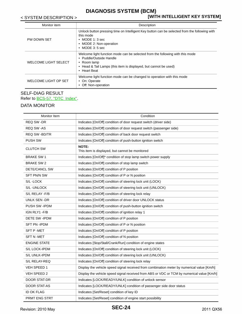
SELF-DIAG RESULTRefer to BCS-57, "DTC Index".
DATA MONITOR
PW DOWN SET
Unlock button pressing time on Intelligent Key button can be selected from the following with this mode• MODE 1: 3 sec• MODE 2: Non-operation• MODE 3: 5 sec
WELCOME LIGHT SELECT
Welcome light function mode can be selected from the following with this mode• Puddle/Outside Handle• Room lamp• Head & Tail Lamps (this item is displayed, but cannot be used)• Heart Beat
WELCOME LIGHT OP SETWelcome light function mode can be changed to operation with this mode• On: Operate• Off: Non-operation
Monitor item Description
Monitor Item Condition
REQ SW -DR Indicates [On/Off] condition of door request switch (driver side)
REQ SW -AS Indicates [On/Off] condition of door request switch (passenger side)
REQ SW -BD/TR Indicates [On/Off] condition of back door request switch
PUSH SW Indicates [On/Off] condition of push-button ignition switch
CLUTCH SWNOTE:This item is displayed, but cannot be monitored
BRAKE SW 1 Indicates [On/Off]* condition of stop lamp switch power supply
BRAKE SW 2 Indicates [On/Off] condition of stop lamp switch
DETE/CANCL SW Indicates [On/Off] condition of P position
SFT PN/N SW Indicates [On/Off] condition of P or N position
S/L -LOCK Indicates [On/Off] condition of steering lock unit (LOCK)
S/L -UNLOCK Indicates [On/Off] condition of steering lock unit (UNLOCK)
S/L RELAY -F/B Indicates [On/Off] condition of steering lock relay
UNLK SEN -DR Indicates [On/Off] condition of driver door UNLOCK status
PUSH SW -IPDM Indicates [On/Off] condition of push-button ignition switch
IGN RLY1 -F/B Indicates [On/Off] condition of ignition relay 1
DETE SW -IPDM Indicates [On/Off] condition of P position
SFT PN -IPDM Indicates [On/Off] condition of P or N position
SFT P -MET Indicates [On/Off] condition of P position
SFT N -MET Indicates [On/Off] condition of N position
ENGINE STATE Indicates [Stop/Stall/Crank/Run] condition of engine states
S/L LOCK-IPDM Indicates [On/Off] condition of steering lock unit (LOCK)
S/L UNLK-IPDM Indicates [On/Off] condition of steering lock unit (UNLOCK)
S/L RELAY-REQ Indicates [On/Off] condition of steering lock relay
VEH SPEED 1 Display the vehicle speed signal received from combination meter by numerical value [Km/h]
VEH SPEED 2 Display the vehicle speed signal received from ABS or VDC or TCM by numerical value [Km/h]
DOOR STAT-DR Indicates [LOCK/READY/UNLK] condition of unlock sensor
DOOR STAT-AS Indicates [LOCK/READY/UNLK] condition of passenger side door status
ID OK FLAG Indicates [Set/Reset] condition of key ID
PRMT ENG STRT Indicates [Set/Reset] condition of engine start possibility
SEC-24Revision: 2010 May 2011 QX56

DIAGNOSIS SYSTEM (BCM)[WITH INTELLIGENT KEY SYSTEM]
C
D
E
F
G
H
I
J
L
M
A
B
EC
N
O
P
< SYSTEM DESCRIPTION >
S
*: OFF is displayed when brake pedal is depressed while brake switch power supply is OFF.
ACTIVE TEST
PRMT RKE STRTNOTE:This item is displayed, but cannot be monitored
TRNK/HAT MNTRNOTE:This item is displayed, but cannot be monitored
RKE-LOCK Indicates [On/Off] condition of LOCK signal from Intelligent Key
RKE-UNLOCK Indicates [On/Off] condition of UNLOCK signal from Intelligent Key
RKE-TR/BDNOTE:This item is displayed, but cannot be monitored
RKE-PANIC Indicates [On/Off] condition of PANIC button of Intelligent Key
RKE-MODE CHG Indicates [On/Off] condition of MODE CHANGE signal from Intelligent Key
RKE OPE COUN1When remote keyless entry receiver receives the signal transmitted while operating on Intelli-gent Key, the numerical value start changing
RKE OPE COUN2NOTE:This item is displayed, but cannot be monitored
Monitor Item Condition
Test item Description
BATTERY SAVERThis test is able to check interior room lamp operation• On: Operate• Off: Non-operation
OUTSIDE BUZZERThis test is able to check Intelligent Key warning buzzer operation• On: Operate• Off: Non-operation
INSIDE BUZZER
This test is able to check warning chime in combination meter operation• Take Out: Take away warning chime sounds when CONSULT-III screen is touched• Key: Key warning chime sounds when CONSULT-III screen is touched• Knob: OFF position warning chime sounds when CONSULT-III screen is touched• Off: Non-operation
INDICATOR
This test is able to check warning lamp operation• KEY ON: “KEY” Warning lamp illuminates when CONSULT-III screen is touched• KEY IND: “KEY” Warning lamp blinks when CONSULT-III screen is touched• Off: Non-operation
INT LAMPThis test is able to check interior room lamp operation• On: Operate• Off: Non-operation
LCD
This test is able to check meter display information• Engine start information displays when “BP N” on CONSULT-III screen is touched• Engine start information displays when “BP I” on CONSULT-III screen is touched• Key ID warning displays when “ID NG” on CONSULT-III screen is touched• Steering lock information displays when “ROTAT” on CONSULT-III screen is touched• P position warning displays when “SFT P” on CONSULT-III screen is touched• INSRT: This item is displayed, but cannot be monitored • BATT: This item is displayed, but cannot be monitored • Take away through window warning displays when “NO KY” on CONSULT-III screen is
touched• Take away warning display when “OUTKEY” on CONSULT-III screen is touched• OFF position warning display when “LK WN” on CONSULT-III screen is touched
FLASHERThis test is able to check security hazard lamp operationThe hazard lamps are activated after “LH/RH/Off” on CONSULT-III screen is touched
P RANGEThis test is able to check A/T shift selector power supply• On: Operate• Off: Non-operation
ENGINE SW ILLUMIThis test is able to check push-button ignition switch illumination operationPush-ignition switch illumination illuminates when “ON” on CONSULT-III screen is touched
SEC-25Revision: 2010 May 2011 QX56

[WITH INTELLIGENT KEY SYSTEM]DIAGNOSIS SYSTEM (BCM)
< SYSTEM DESCRIPTION >
THEFT ALM
THEFT ALM : CONSULT-III Function (BCM - THEFT) INFOID:0000000006226189
DATA MONITOR
WORK SUPPORT
LOCK INDICATORThis test is able to check LOCK indicator (push-button ignition switch) operation• On: Operate• Off: Non-operation
ACC INDICATORThis test is able to check ACC indicator (push-button ignition switch) operation• On: Operate• Off: Non-operation
IGNITION ON INDThis test is able to check ON indicator (push-button ignition switch) operation• On: Operate• Off: Non-operation
HORNThis test is able to check horn operation• On: Operate• Off: Non-operation
TRUNK/BACK DOORNOTE:This item is displayed, but cannot be used
Test item Description
Monitored Item Description
REQ SW -DR Indicates [ON/OFF] condition of door request switch (driver side).
REQ SW -AS Indicates [ON/OFF] condition of door request switch (passenger side).
REQ SW -RRNOTE:This item is displayed, but cannot be monitored.
REQ SW -RLNOTE:This item is displayed, but cannot be monitored.
REQ SW -BD/TR Indicates [ON/OFF] condition of back door request switch.
PUSH SW Indicates [ON/OFF] condition of push-button ignition switch
UNLK SEN -DR Indicates [ON/OFF] condition of driver door UNLOCK status.
DOOR SW-DR Indicates [ON/OFF] condition of front door switch (driver side).
DOOR SW-AS Indicates [ON/OFF] condition of front door switch (passenger side).
DOOR SW-RR Indicates [ON/OFF] condition of rear door switch RH.
DOOR SW-RL Indicates [ON/OFF] condition of rear door switch LH.
DOOR SW-BK Indicates [ON/OFF] condition of back door switch.
CDL LOCK SW Indicates [ON/OFF] condition of lock signal from door lock/unlock switch LH and RH.
CDL UNLOCK SW Indicates [ON/OFF] condition of unlock signal from door lock/unlock switch LH and RH.
KEY CYL LK-SW Indicates [ON/OFF] condition of lock signal from door key cylinder.
KEY CYL UN-SW Indicates [ON/OFF] condition of unlock signal from door key cylinder.
TR/BD OPEN SW Indicates [ON/OFF] condition of back door opener switch.
TRNK/HAT MNTRNOTE:This item is displayed, but cannot be monitored.
RKE-LOCK Indicates [ON/OFF] condition of LOCK signal from Intelligent Key.
RKE-UNLOCK Indicates [ON/OFF] condition of UNLOCK signal from Intelligent Key.
RKE-TR/BDNOTE:This item is displayed, but cannot be monitored.
SEC-26Revision: 2010 May 2011 QX56

DIAGNOSIS SYSTEM (BCM)[WITH INTELLIGENT KEY SYSTEM]
C
D
E
F
G
H
I
J
L
M
A
B
EC
N
O
P
< SYSTEM DESCRIPTION >
S
ACTIVE TEST
IMMU
IMMU : CONSULT-III Function (BCM - IMMU) INFOID:0000000006226190
DATA MONITOR
ACTIVE TEST
WORK SUPPORT
Service Item Description
SECURITY ALARM SET This mode is able to confirm and change security alarm ON-OFF setting.
THEFT ALM TRGThe switch which triggered vehicle security alarm is recorded.This mode is able to confirm and erase the record of vehicle security alarm.The trigger data can be erased by touching “CLEAR” on CONSULT-III screen.
Test Item Description
THEFT INDThis test is able to check security indicator lamp operation. Security indicator lamp is turned on when “ON” on CONSULT-III screen is touched.
VEHICLE SECURITY HORNThis test is able to check horn operation. Horn is activated for 0.5 seconds after “ON” on CONSULT-III screen is touched.
HEADLAMP(HI)This test is able to check headlamp operation. Headlamps are activated for 0.5 seconds after “ON” on CONSULT-III screen is touched.
FLASHERThis test is able to check hazard warning lamp operation. Hazard warning lamps are activated after “ON” on CONSULT-III screen is touched.
Monitor item Content
CONFRM ID ALL
Indicates [YET] at all time.Switches to [DONE] when a registered Intelligent Key backside is contacted to push-button ignition switch.
CONFIRM ID4
CONFIRM ID3
CONFIRM ID2
CONFIRM ID1
NOT REGISTEREDIndicates [ID OK] when key ID that is registered is received or is not yet received.Indicates [ID NG] when key ID that is not registered is received.
TP 4
Indicates the number of IDs that are registered.TP 3
TP 2
TP 1
PUSH SW Indicates [ON/OFF] condition of push-button ignition switch.
Test item Description
THEFT INDThis test is able to check security indicator lamp operation.Security indicator lamp is turned on when “ON” on CONSULT-III screen touched.
Service item Description
CONFIRM DONGLE ID It is possible to check that dongle unit is applied to the vehicle.
SEC-27Revision: 2010 May 2011 QX56

[WITH INTELLIGENT KEY SYSTEM]DIAGNOSIS SYSTEM (IPDM E/R)
< SYSTEM DESCRIPTION >
DIAGNOSIS SYSTEM (IPDM E/R)
CONSULT-III Function (IPDM E/R) INFOID:0000000006365348
APPLICATION ITEMCONSULT-III performs the following functions via CAN communication with IPDM E/R.
SELF DIAGNOSTIC RESULTRefer to PCS-22, "DTC Index".
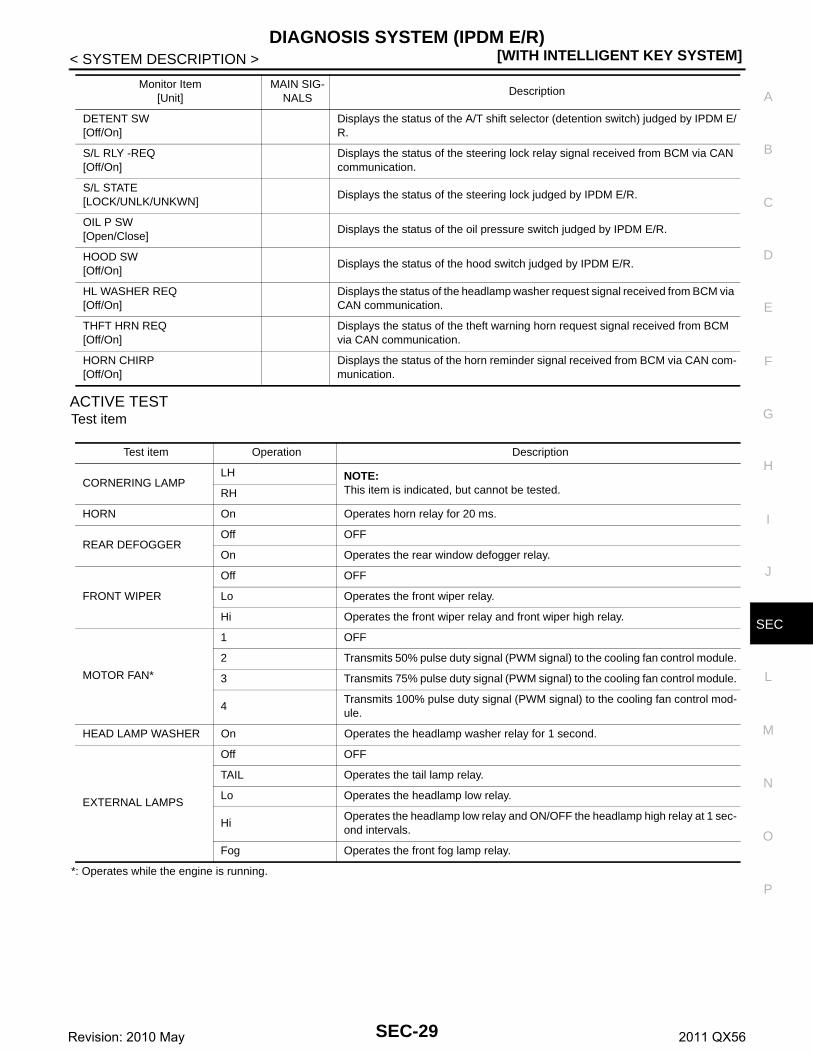
DATA MONITORMonitor item
Diagnosis mode Description
Ecu Identification Allows confirmation of IPDM E/R part number.
Self Diagnostic Result Displays the diagnosis results judged by IPDM E/R.
Data Monitor Displays the real-time input/output data from IPDM E/R input/output data.
Active Test IPDM E/R can provide a drive signal to electronic components to check their operations.
CAN Diag Support Monitor The results of transmit/receive diagnosis of CAN communication can be read.
Monitor Item[Unit]
MAIN SIG-NALS
Description
RAD FAN REQ[1/2/3/4]
× Displays the value of the cooling fan speed request signal received from ECM via CAN communication.
AC COMP REQ[Off/On]
× Displays the status of the A/C compressor request signal received from ECM via CAN communication.
TAIL&CLR REQ[Off/On]
× Displays the status of the position light request signal received from BCM via CAN communication.
HL LO REQ[Off/On]
× Displays the status of the low beam request signal received from BCM via CAN communication.
HL HI REQ[Off/On]
× Displays the status of the high beam request signal received from BCM via CAN communication.
FR FOG REQ[Off/On]
× Displays the status of the front fog light request signal received from BCM via CAN communication.
FR WIP REQ[Stop/1LOW/Low/Hi]
× Displays the status of the front wiper request signal received from BCM via CAN communication.
WIP AUTO STOP[STOP P/ACT P]
× Displays the status of the front wiper auto stop signal judged by IPDM E/R.
WIP PROT[Off/BLOCK]
× Displays the status of the front wiper fail-safe operation judged by IPDM E/R.
IGN RLY1 -REQ[Off/On]
Displays the status of the ignition switch ON signal received from BCM via CAN communication.
IGN RLY[Off/On]
× Displays the status of the ignition relay judged by IPDM E/R.
PUSH SW[Off/On]
Displays the status of the push-button ignition switch judged by IPDM E/R.
INTER/NP SW[Off/On]
Displays the status of the shift position judged by IPDM E/R.
ST RLY CONT[Off/On]
Displays the status of the starter relay status signal received from BCM via CAN communication.
IHBT RLY -REQ[Off/On]
Displays the status of the starter control relay signal received from BCM via CAN communication.
ST/INHI RLY[Off/ ST ON/INHI ON/UNKWN]
Displays the status of the starter relay and starter control relay judged by IPDM E/R.
SEC-28Revision: 2010 May 2011 QX56
DIAGNOSIS SYSTEM (IPDM E/R)[WITH INTELLIGENT KEY SYSTEM]
C
D
E
F
G
H
I
J
L
M
A
B
EC
N
O
P
< SYSTEM DESCRIPTION >
S
ACTIVE TESTTest item
*: Operates while the engine is running.
DETENT SW[Off/On]
Displays the status of the A/T shift selector (detention switch) judged by IPDM E/R.
S/L RLY -REQ[Off/On]
Displays the status of the steering lock relay signal received from BCM via CAN communication.
S/L STATE[LOCK/UNLK/UNKWN]
Displays the status of the steering lock judged by IPDM E/R.
OIL P SW[Open/Close]
Displays the status of the oil pressure switch judged by IPDM E/R.
HOOD SW[Off/On]
Displays the status of the hood switch judged by IPDM E/R.
HL WASHER REQ[Off/On]
Displays the status of the headlamp washer request signal received from BCM via CAN communication.
THFT HRN REQ[Off/On]
Displays the status of the theft warning horn request signal received from BCM via CAN communication.
HORN CHIRP[Off/On]
Displays the status of the horn reminder signal received from BCM via CAN com-munication.
Monitor Item[Unit]
MAIN SIG-NALS
Description
Test item Operation Description
CORNERING LAMPLH NOTE:
This item is indicated, but cannot be tested.RH
HORN On Operates horn relay for 20 ms.
REAR DEFOGGEROff OFF
On Operates the rear window defogger relay.
FRONT WIPER
Off OFF
Lo Operates the front wiper relay.
Hi Operates the front wiper relay and front wiper high relay.
MOTOR FAN*
1 OFF
2 Transmits 50% pulse duty signal (PWM signal) to the cooling fan control module.
3 Transmits 75% pulse duty signal (PWM signal) to the cooling fan control module.
4Transmits 100% pulse duty signal (PWM signal) to the cooling fan control mod-ule.
HEAD LAMP WASHER On Operates the headlamp washer relay for 1 second.
EXTERNAL LAMPS
Off OFF
TAIL Operates the tail lamp relay.
Lo Operates the headlamp low relay.
HiOperates the headlamp low relay and ON/OFF the headlamp high relay at 1 sec-ond intervals.
Fog Operates the front fog lamp relay.
SEC-29Revision: 2010 May 2011 QX56

[WITH INTELLIGENT KEY SYSTEM]ECM, IPDM E/R, BCM
< ECU DIAGNOSIS INFORMATION >
ECU DIAGNOSIS INFORMATIONECM, IPDM E/R, BCM
List of ECU Reference INFOID:0000000006226193
ECU Reference
ECM
Reference Value EC-72, "Reference Value"
Fail-safe EC-93, "Fail-safe"
DTC Inspection Priority Chart EC-96, "DTC Inspection Priority Chart"
DTC Index EC-98, "DTC Index"
IPDM E/R
Reference Value PCS-15, "Reference Value"
Fail-safe PCS-21, "Fail-Safe"
DTC Index PCS-22, "DTC Index"
BCM
Reference Value BCS-33, "Reference Value"
Fail-safe BCS-54, "Fail-safe"
DTC Inspection Priority Chart BCS-56, "DTC Inspection Priority Chart"
DTC Index BCS-57, "DTC Index"
SEC-30Revision: 2010 May 2011 QX56

SECURITY CONTROL SYSTEM[WITH INTELLIGENT KEY SYSTEM]
C
D
E
F
G
H
I
J
L
M
A
B
EC
N
O
P
< WIRING DIAGRAM >
S
WIRING DIAGRAMSECURITY CONTROL SYSTEM
Wiring Diagram INFOID:0000000006226195
For connector terminal arrangements, harness layouts, and alphabets in a (option abbreviation; if notdescribed in wiring diagram), refer to GI-12, "Connector Information".
JCKWM4456GB
SEC-31Revision: 2010 May 2011 QX56

[WITH INTELLIGENT KEY SYSTEM]SECURITY CONTROL SYSTEM
< WIRING DIAGRAM >
JCKWM4457GB
SEC-32Revision: 2010 May 2011 QX56

SECURITY CONTROL SYSTEM[WITH INTELLIGENT KEY SYSTEM]
C
D
E
F
G
H
I
J
L
M
A
B
EC
N
O
P
< WIRING DIAGRAM >
S
JCKWM4458GB
SEC-33Revision: 2010 May 2011 QX56

[WITH INTELLIGENT KEY SYSTEM]SECURITY CONTROL SYSTEM
< WIRING DIAGRAM >
JCKWM4459GB
SEC-34Revision: 2010 May 2011 QX56

SECURITY CONTROL SYSTEM[WITH INTELLIGENT KEY SYSTEM]
C
D
E
F
G
H
I
J
L
M
A
B
EC
N
O
P
< WIRING DIAGRAM >
S
JCKWM4460GB
SEC-35Revision: 2010 May 2011 QX56

[WITH INTELLIGENT KEY SYSTEM]SECURITY CONTROL SYSTEM
< WIRING DIAGRAM >
JCKWM4461GB
SEC-36Revision: 2010 May 2011 QX56
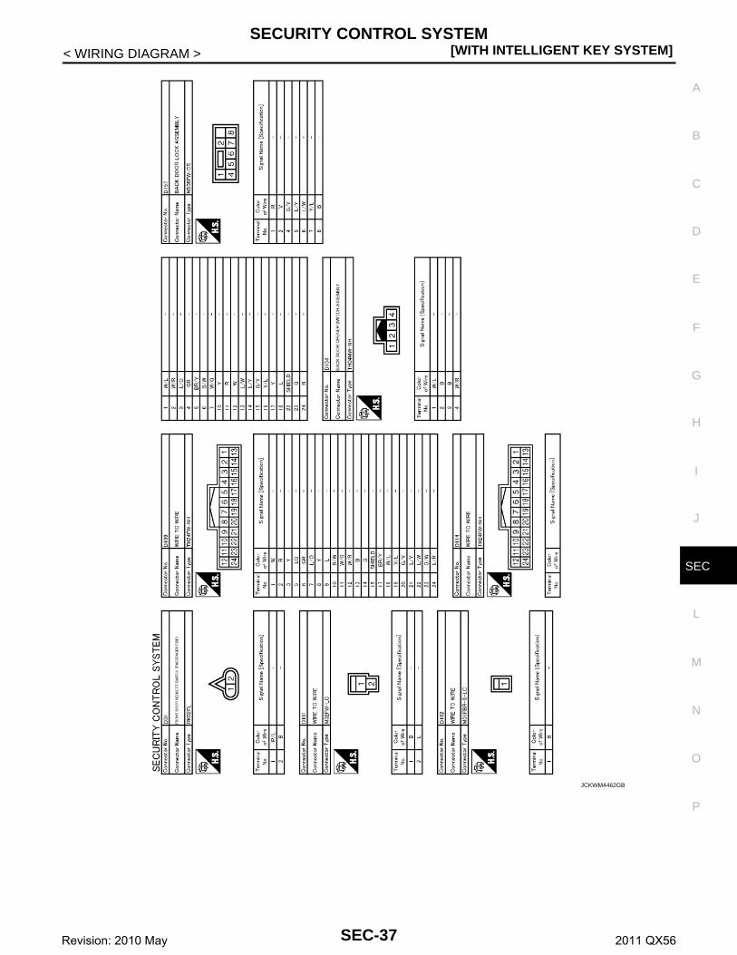
SECURITY CONTROL SYSTEM[WITH INTELLIGENT KEY SYSTEM]
C
D
E
F
G
H
I
J
L
M
A
B
EC
N
O
P
< WIRING DIAGRAM >
S
JCKWM4462GB
SEC-37Revision: 2010 May 2011 QX56

[WITH INTELLIGENT KEY SYSTEM]SECURITY CONTROL SYSTEM
< WIRING DIAGRAM >
JCKWM4463GB
SEC-38Revision: 2010 May 2011 QX56

SECURITY CONTROL SYSTEM[WITH INTELLIGENT KEY SYSTEM]
C
D
E
F
G
H
I
J
L
M
A
B
EC
N
O
P
< WIRING DIAGRAM >
S
JCKWM4464GB
SEC-39Revision: 2010 May 2011 QX56

[WITH INTELLIGENT KEY SYSTEM]SECURITY CONTROL SYSTEM
< WIRING DIAGRAM >
JCKWM4465GB
SEC-40Revision: 2010 May 2011 QX56

SECURITY CONTROL SYSTEM[WITH INTELLIGENT KEY SYSTEM]
C
D
E
F
G
H
I
J
L
M
A
B
EC
N
O
P
< WIRING DIAGRAM >
S
JCKWM4466GB
SEC-41Revision: 2010 May 2011 QX56

[WITH INTELLIGENT KEY SYSTEM]SECURITY CONTROL SYSTEM
< WIRING DIAGRAM >
JCKWM4467GB
SEC-42Revision: 2010 May 2011 QX56

SECURITY CONTROL SYSTEM[WITH INTELLIGENT KEY SYSTEM]
C
D
E
F
G
H
I
J
L
M
A
B
EC
N
O
P
< WIRING DIAGRAM >
S
JCKWM4468GB
SEC-43Revision: 2010 May 2011 QX56

[WITH INTELLIGENT KEY SYSTEM]SECURITY CONTROL SYSTEM
< WIRING DIAGRAM >
JCKWM4469GB
SEC-44Revision: 2010 May 2011 QX56

SECURITY CONTROL SYSTEM[WITH INTELLIGENT KEY SYSTEM]
C
D
E
F
G
H
I
J
L
M
A
B
EC
N
O
P
< WIRING DIAGRAM >
S
JCKWM4470GB
SEC-45Revision: 2010 May 2011 QX56
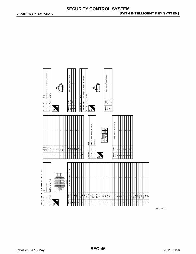
[WITH INTELLIGENT KEY SYSTEM]SECURITY CONTROL SYSTEM
< WIRING DIAGRAM >
JCKWM4471GB
SEC-46Revision: 2010 May 2011 QX56

SECURITY CONTROL SYSTEM[WITH INTELLIGENT KEY SYSTEM]
C
D
E
F
G
H
I
J
L
M
A
B
EC
N
O
P
< WIRING DIAGRAM >
S
JCKWM4472GB
SEC-47Revision: 2010 May 2011 QX56

[WITH INTELLIGENT KEY SYSTEM]DIAGNOSIS AND REPAIR WORK FLOW
< BASIC INSPECTION >
BASIC INSPECTIONDIAGNOSIS AND REPAIR WORK FLOW
Work Flow INFOID:0000000006226196
OVERALL SEQUENCE
DETAILED FLOW
JMKIA3449GB
SEC-48Revision: 2010 May 2011 QX56

DIAGNOSIS AND REPAIR WORK FLOW[WITH INTELLIGENT KEY SYSTEM]
C
D
E
F
G
H
I
J
L
M
A
B
EC
N
O
P
< BASIC INSPECTION >
S
1.GET INFORMATION ABOUT SYMPTOM
Get detailed information from the customer about the symptom (the condition and the environment when theincident/malfunction occurs).
>> GO TO 2.
2.CHECK DTC
1. Check DTC of “ENGINE”, “BCM” and “IPDM E/R” using CONSULT-III.2. Perform the following procedure if DTC is detected.- Record DTC and freeze frame data (Print them out using CONSULT-III.)- Erase DTC.- Study the relationship between the cause detected by DTC and the symptom described by the customer.3. Check related service bulletins for information.Are any symptoms described and any DTC detected?Symptom is described, DTC is detected>>GO TO 3.Symptom is described, DTC is not detected>>GO TO 4.Symptom is not described, DTC is detected>>GO TO 5.
3.CONFIRM THE SYMPTOM
Confirm the symptom described by the customer.Connect CONSULT-III to the vehicle, and check self diagnostic results in real time.Verify relation between the symptom and the condition when the symptom is detected.
>> GO TO 5.
4.CONFIRM THE SYMPTOM
Confirm the symptom described by the customer.Connect CONSULT-III to the vehicle, and check self diagnostic results in real time.Verify relation between the symptom and the condition when the symptom is detected.
>> GO TO 6.
5.PERFORM DTC CONFIRMATION PROCEDURE
Perform DTC Confirmation Procedure for the detected DTC, and then check that DTC is detected again.At this time, always connect CONSULT-III to the vehicle, and check self diagnostic results in real time.If two or more DTCs are detected, refer to BCS-56, "DTC Inspection Priority Chart" (BCM) or PCS-22,"DTC Index" (IPDM E/R), and determine trouble diagnosis order.Is DTC detected?YES >> GO TO 7.NO >> Refer to GI-40, "Intermittent Incident".
6.DETECT MALFUNCTIONING SYSTEM BY SYMPTOM DIAGNOSIS
Detect malfunctioning system according to SYMPTOM DIAGNOSIS based on the confirmed symptom in step4, and determine the trouble diagnosis order based on possible causes and symptom.
>> GO TO 7.
7.DETECT MALFUNCTIONING PART BY DIAGNOSTIC PROCEDURE
Inspect according to Diagnostic Procedure of the system.NOTE:The Diagnostic Procedure is described based on open and short circuit inspection. Is malfunctioning part detected?YES >> GO TO 8.NO >> Check voltage of related BCM terminals or IPDM E/R terminals using CONSULT-III.
8.REPAIR OR REPLACE THE MALFUNCTIONING PART
1. Repair or replace the malfunctioning part.
SEC-49Revision: 2010 May 2011 QX56

[WITH INTELLIGENT KEY SYSTEM]DIAGNOSIS AND REPAIR WORK FLOW
< BASIC INSPECTION >2. Reconnect parts or connectors disconnected during Diagnostic Procedure again after repair and replace-
ment.3. Check DTC. If DTC is detected, erase it.
>> GO TO 9.
9.FINAL CHECK
When DTC is detected in step 2, perform DTC CONFIRMATION PROCEDURE again, and then check that themalfunction is repaired securely.When symptom is described by the customer, refer to confirmed symptom in step 3 or 4, and check that thesymptom is not detected.Does the symptom reappear?YES (DTC is detected)>>GO TO 7.YES (Symptom remains)>>GO TO 6.NO >> INSPECTION END
SEC-50Revision: 2010 May 2011 QX56

ADDITIONAL SERVICE WHEN REPLACING CONTROL UNIT[WITH INTELLIGENT KEY SYSTEM]
C
D
E
F
G
H
I
J
L
M
A
B
EC
N
O
P
< BASIC INSPECTION >
S
ADDITIONAL SERVICE WHEN REPLACING CONTROL UNITECM
ECM : Description INFOID:0000000006226197
Performing the following procedure can automatically activate recommunication of ECM and BCM, but onlywhen the ECM is replaced with a new one*.*: New one means a virgin ECM that has never been energized on-board.(In this step, initialization procedure by CONSULT-III is not necessary)NOTE:• When registering new Key IDs or replacing the ECM that is not brand new, refer to CONSULT-III Oper-
ation Manual NATS-IVIS/NVIS.• If multiple keys are attached to the key holder, separate them before beginning work.• Distinguish keys with unregistered key IDs from those with registered IDs.
ECM : Work Procedure INFOID:0000000006226198
1.PERFORM ECM RECOMMUNICATING FUNCTION
1. Install ECM.2. Contact backside of registered Intelligent key* to push-button ignition switch, then turn power supply posi-
tion to ON.*: To perform this step, use the key that is used before performing ECM replacement.
3. Maintain power supply position in the ON position for at least 5 seconds.4. Turn power supply position to OFF.5. Check that the engine starts.
>> GO TO 2.
2.PERFORM ADDITIONAL SERVICE WHEN REPLACING ECM
Perform EC-143, "Work Procedure".
>> ENDBCM
BCM : Description INFOID:0000000006397657
BEFORE REPLACEMENTWhen replacing BCM, save or print current vehicle specification with CONSULT-III configuration beforereplacement.NOTE:If “READ CONFIGURATION” can not be used, use the “WRITE CONFIGURATION - Manual selection” afterreplacing BCM.
AFTER REPLACEMENTCAUTION:• When replacing BCM, you must perform “WRITE CONFIGURATION” with CONSULT-III.- Complete the procedure of “WRITE CONFIGURATION” in order.- If you set incorrect “WRITE CONFIGURATION”, incidents might occur.- Configuration is different for each vehicle model. Confirm configuration of each vehicle model.• When replacing BCM, perform the system initialization (NATS).
BCM : Work Procedure INFOID:0000000006397658
1.SAVING VEHICLE SPECIFICATION
CONSULT-III ConfigurationPerform “READ CONFIGURATION” to save or print current vehicle specification. Refer to BCS-67, "CONFIG-URATION (BCM) : Description".NOTE:
SEC-51Revision: 2010 May 2011 QX56

[WITH INTELLIGENT KEY SYSTEM]ADDITIONAL SERVICE WHEN REPLACING CONTROL UNIT
< BASIC INSPECTION >If “READ CONFIGURATION” can not be used, use the “WRITE CONFIGURATION - Manual selection” afterreplacing BCM.
>> GO TO 2.
2.REPLACE BCM
Replace BCM. Refer toBCS-81, "Removal and Installation".
>> GO TO 3.
3.WRITING VEHICLE SPECIFICATION
CONSULT-III ConfigurationPerform “WRITE CONFIGURATION - Config file” or “WRITE CONFIGURATION - Manual selection” to writevehicle specification. Refer to BCS-69, "CONFIGURATION (BCM) : Configuration list".
>> GO TO 4.
4.INITIALIZE BCM (NATS)
Perform BCM initialization. (NATS)
>> WORK END
SEC-52Revision: 2010 May 2011 QX56
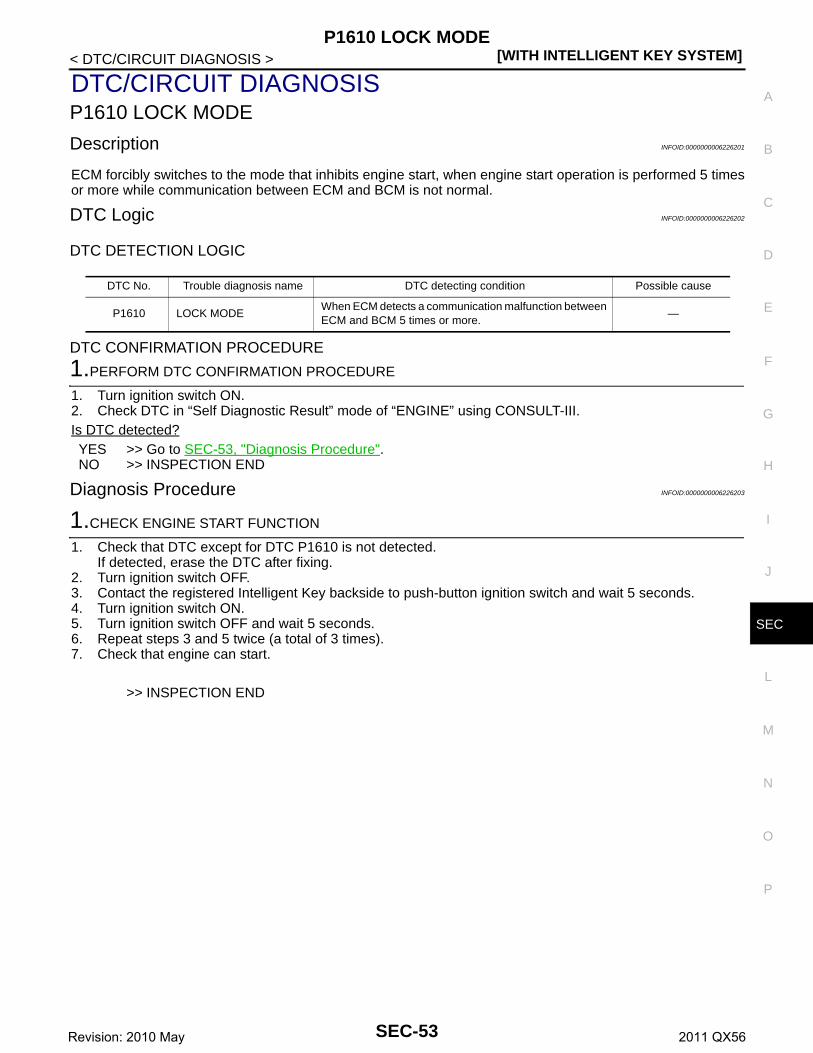
P1610 LOCK MODE[WITH INTELLIGENT KEY SYSTEM]
C
D
E
F
G
H
I
J
L
M
A
B
EC
N
O
P
< DTC/CIRCUIT DIAGNOSIS >
S
DTC/CIRCUIT DIAGNOSISP1610 LOCK MODE
Description INFOID:0000000006226201
ECM forcibly switches to the mode that inhibits engine start, when engine start operation is performed 5 timesor more while communication between ECM and BCM is not normal.
DTC Logic INFOID:0000000006226202
DTC DETECTION LOGIC
DTC CONFIRMATION PROCEDURE
1.PERFORM DTC CONFIRMATION PROCEDURE
1. Turn ignition switch ON.2. Check DTC in “Self Diagnostic Result” mode of “ENGINE” using CONSULT-III.Is DTC detected?YES >> Go to SEC-53, "Diagnosis Procedure".NO >> INSPECTION END
Diagnosis Procedure INFOID:0000000006226203
1.CHECK ENGINE START FUNCTION
1. Check that DTC except for DTC P1610 is not detected.If detected, erase the DTC after fixing.
2. Turn ignition switch OFF.3. Contact the registered Intelligent Key backside to push-button ignition switch and wait 5 seconds.4. Turn ignition switch ON.5. Turn ignition switch OFF and wait 5 seconds.6. Repeat steps 3 and 5 twice (a total of 3 times).7. Check that engine can start.
>> INSPECTION END
DTC No. Trouble diagnosis name DTC detecting condition Possible cause
P1610 LOCK MODEWhen ECM detects a communication malfunction between ECM and BCM 5 times or more.
—
SEC-53Revision: 2010 May 2011 QX56
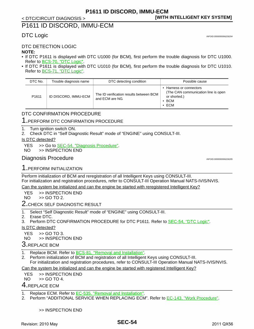
[WITH INTELLIGENT KEY SYSTEM]P1611 ID DISCORD, IMMU-ECM
< DTC/CIRCUIT DIAGNOSIS >
P1611 ID DISCORD, IMMU-ECM
DTC Logic INFOID:0000000006226204
DTC DETECTION LOGICNOTE:• If DTC P1611 is displayed with DTC U1000 (for BCM), first perform the trouble diagnosis for DTC U1000.
Refer to BCS-70, "DTC Logic".• If DTC P1611 is displayed with DTC U1010 (for BCM), first perform the trouble diagnosis for DTC U1010.
Refer to BCS-71, "DTC Logic".
DTC CONFIRMATION PROCEDURE
1.PERFORM DTC CONFIRMATION PROCEDURE
1. Turn ignition switch ON.2. Check DTC in “Self Diagnostic Result” mode of “ENGINE” using CONSULT-III.Is DTC detected?YES >> Go to SEC-54, "Diagnosis Procedure".NO >> INSPECTION END
Diagnosis Procedure INFOID:0000000006226205
1.PERFORM INITIALIZATION
Perform initialization of BCM and reregistration of all Intelligent Keys using CONSULT-III.For initialization and registration procedures, refer to CONSULT-III Operation Manual NATS-IVIS/NVIS.Can the system be initialized and can the engine be started with reregistered Intelligent Key?YES >> INSPECTION ENDNO >> GO TO 2.
2.CHECK SELF DIAGNOSTIC RESULT
1. Select “Self Diagnostic Result” mode of “ENGINE” using CONSULT-III.2. Erase DTC.3. Perform DTC CONFIRMATION PROCEDURE for DTC P1611. Refer to SEC-54, "DTC Logic".Is DTC detected?YES >> GO TO 3.NO >> INSPECTION END
3.REPLACE BCM
1. Replace BCM. Refer to BCS-81, "Removal and Installation".2. Perform initialization of BCM and registration of all Intelligent Keys using CONSULT-III.
For initialization and registration procedures, refer to CONSULT-III Operation Manual NATS-IVIS/NVIS.Can the system be initialized and can the engine be started with registered Intelligent Key?YES >> INSPECTION ENDNO >> GO TO 4.
4.REPLACE ECM
1. Replace ECM. Refer to EC-535, "Removal and Installation".2. Perform “ADDITIONAL SERVICE WHEN REPLACING ECM”. Refer to EC-143, "Work Procedure".
>> INSPECTION END
DTC No. Trouble diagnosis name DTC detecting condition Possible cause
P1611 ID DISCORD, IMMU-ECMThe ID verification results between BCM and ECM are NG.
• Harness or connectors(The CAN communication line is open or shorted.)
• BCM• ECM
SEC-54Revision: 2010 May 2011 QX56

P1612 CHAIN OF ECM-IMMU[WITH INTELLIGENT KEY SYSTEM]
C
D
E
F
G
H
I
J
L
M
A
B
EC
N
O
P
< DTC/CIRCUIT DIAGNOSIS >
S
P1612 CHAIN OF ECM-IMMU
DTC Logic INFOID:0000000006226206
DTC DETECTION LOGICNOTE:• If DTC P1612 is displayed with DTC U1000 (for BCM), first perform the trouble diagnosis for DTC U1000.
Refer to BCS-70, "DTC Logic".• If DTC P1612 is displayed with DTC U1010 (for BCM), first perform the trouble diagnosis for DTC U1010.
Refer to BCS-71, "DTC Logic".
DTC CONFIRMATION PROCEDURE
1.PERFORM DTC CONFIRMATION PROCEDURE
1. Turn ignition switch ON.2. Check DTC in “Self Diagnostic Result” mode of “ENGINE” using CONSULT-III.Is DTC detected?YES >> Go to SEC-55, "Diagnosis Procedure".NO >> INSPECTION END
Diagnosis Procedure INFOID:0000000006226207
1.REPLACE BCM
1. Replace BCM. Refer to BCS-81, "Removal and Installation".2. Perform initialization of BCM and registration of all Intelligent Keys using CONSULT-III.
For initialization and registration procedures, refer to CONSULT-III Operation Manual NATS-IVIS/NVIS.Can the system be initialized and can the engine be started with registered Intelligent Key?YES >> INSPECTION ENDNO >> GO TO 2.
2.REPLACE ECM
1. Replace ECM. Refer to EC-535, "Removal and Installation".2. Perform “ADDITIONAL SERVICE WHEN REPLACING ECM”. Refer to EC-143, "Work Procedure".
>> INSPECTION END
DTC No. Trouble diagnosis name DTC detecting condition Possible cause
P1612 CHAIN OF ECM-IMMUInactive communication between ECM and BCM
• Harness or connectors(The CAN communication line is open or shorted.)
• BCM • ECM
SEC-55Revision: 2010 May 2011 QX56

[WITH INTELLIGENT KEY SYSTEM]P1614 CHAIN OF IMMU-KEY
< DTC/CIRCUIT DIAGNOSIS >
P1614 CHAIN OF IMMU-KEY
DTC Logic INFOID:0000000006226208
DTC DETECTION LOGIC
DTC CONFIRMATION PROCEDURE
1.PERFORM DTC CONFIRMATION PROCEDURE 1
1. Contact Intelligent Key backside to push-button ignition switch.2. Check DTC in “Self Diagnostic Result” mode of “ENGINE” using CONSULT-III.Is DTC detected?YES >> Go to SEC-56, "Diagnosis Procedure".NO >> GO TO 2.
2.PERFORM DTC CONFIRMATION PROCEDURE 2
1. Press the push-button ignition switch.2. Check DTC in “Self Diagnostic Result” mode of “ENGINE” using CONSULT-III.Is DTC detected?YES >> Go to SEC-56, "Diagnosis Procedure".NO >> INSPECTION END
Diagnosis Procedure INFOID:0000000006226209
1.CHECK FUSE
1. Turn ignition switch OFF.2. Check that the following fuse in IPDM E/R is not blown.
Is the fuse fusing?YES >> Replace the blown fuse after repairing the cause of blowing.NO >> GO TO 2.
2.CHECK NATS ANTENNA AMP. POWER SUPPLY
1. Disconnect NATS antenna amp. connector.2. Check voltage between NATS antenna amp. harness connector and ground.
Is the inspection result normal?YES >> GO TO 4.NO >> GO TO 3.
3.CHECK NATS ANTENNA AMP. POWER SUPPLY CIRCUIT
1. Disconnect IPDM E/R connector.2. Check continuity between IPDM E/R harness connector and NATS antenna amp. connector.
DTC No. Trouble diagnosis name DTC detecting condition Possible cause
P1614 CHAIN OF IMMU-KEYInactive communication between NATS antenna amp. and BCM
• Harness or connectors(NATS antenna amp. circuit is open or shorted.)
• NATS antenna amp.• IPDM E/R
Signal name Fuse No.
Battery power supply 43
(+)
(–)Voltage (V)(Approx.)
NATS antenna amp.
Connector Terminal
M26 1 Ground Battery voltage
SEC-56Revision: 2010 May 2011 QX56

P1614 CHAIN OF IMMU-KEY[WITH INTELLIGENT KEY SYSTEM]
C
D
E
F
G
H
I
J
L
M
A
B
EC
N
O
P
< DTC/CIRCUIT DIAGNOSIS >
S
3. Check continuity between IPDM E/R harness connector and ground.
Is the inspection result normal?YES >> Replace IPDM E/R. Refer to PCS-32, "Removal and Installation".NO >> Repair or replace harness.
4.CHECK NATS ANTENNA AMP. OUTPUT SIGNAL 1
1. Connect NATS antenna amp. connector.2. Disconnect BCM connector.3. Check voltage between BCM harness connector and ground.
Is the inspection result normal?YES >> GO TO 6.NO >> GO TO 5.
5.CHECK NATS ANTENNA AMP. OUTPUT SIGNAL CIRCUIT 1
1. Disconnect NATS antenna amp. connector.2. Check continuity between BCM harness connector and NATS antenna amp. connector.
3. Check continuity between BCM harness connector and ground.
Is the inspection result normal?YES >> Replace NATS antenna amp. Refer to SEC-155, "Removal and Installation".NO >> Repair or replace harness.
6.CHECK NATS ANTENNA AMP. COMMUNICATION SIGNAL 1
1. Connect BCM connector.2. Check voltage between BCM harness connector and ground using analog tester.
Is the inspection result normal?
IPDM E/R NATS antenna amp.Continuity
Connector Terminal Connector Terminal
E14 42 M26 1 Existed
IPDM E/R
GroundContinuity
Connector Terminal
E14 42 Not existed
(+)
(–)Voltage (V)(Approx.)
BCM
Connector Terminal
M68 21 Ground 12
BCM NATS antenna amp.Continuity
Connector Terminal Connector Terminal
M68 21 M26 2 Existed
BCM
GroundContinuity
Connector Terminal
M68 21 Not existed
(+)
(–) ConditionVoltage (V)(Approx.)
BCM
Connector Terminal
M68 21 GroundContact Intelligent Key backside to push-button ignition switch, then turn ignition switch ON.
Just after pressing push-button ignition switch, pointer of analog tester should move.
SEC-57Revision: 2010 May 2011 QX56

[WITH INTELLIGENT KEY SYSTEM]P1614 CHAIN OF IMMU-KEY
< DTC/CIRCUIT DIAGNOSIS >YES >> GO TO 7.NO >> Replace NATS antenna amp. Refer to SEC-155, "Removal and Installation".
7.CHECK NATS ANTENNA AMP. OUTPUT SIGNAL 2
1. Disconnect BCM connector.2. Check voltage between BCM harness connector and ground.
Is the inspection result normal?YES >> GO TO 9.NO >> GO TO 8.
8.CHECK NATS ANTENNA AMP. OUTPUT SIGNAL CIRCUIT 2
1. Disconnect NATS antenna amp. connector.2. Check continuity between BCM harness connector and NATS antenna amp. connector.
3. Check continuity between BCM harness connector and ground.
Is the inspection result normal?YES >> Replace NATS antenna amp. Refer to SEC-155, "Removal and Installation".NO >> Repair or replace harness.
9.CHECK NATS ANTENNA AMP. COMMUNICATION SIGNAL 2
1. Connect BCM connector.2. Check voltage between BCM harness connector and ground using analog tester.
Is the inspection result normal?YES >> GO TO 10.NO >> Replace NATS antenna amp. Refer to SEC-155, "Removal and Installation".
10.CHECK NATS ANTENNA AMP. GROUND CIRCUIT
1. Disconnect NATS antenna amp. connector.2. Check continuity between NATS antenna amp. harness connector and ground.
Is the inspection result normal?
(+)
(–)Voltage (V)(Approx.)
BCM
Connector Terminal
M68 25 Ground 12
BCM NATS antenna amp.Continuity
Connector Terminal Connector Terminal
M68 25 M26 3 Existed
BCM
GroundContinuity
Connector Terminal
M68 25 Not existed
(+)
(–) ConditionVoltage (V)(Approx.)
BCM
Connector Terminal
M68 25 GroundContact Intelligent Key backside to push-button ignition switch, then turn ignition switch ON.
Just after pressing push-button ignition switch, pointer of analog tester should move.
NATS antenna amp.
GroundContinuity
Connector Terminal
M26 4 Existed
SEC-58Revision: 2010 May 2011 QX56

P1614 CHAIN OF IMMU-KEY[WITH INTELLIGENT KEY SYSTEM]
C
D
E
F
G
H
I
J
L
M
A
B
EC
N
O
P
< DTC/CIRCUIT DIAGNOSIS >
S
YES >> GO TO 11.NO >> Repair or replace harness.
11.CHECK INTERMITTENT INCIDENT
Refer to GI-40, "Intermittent Incident".
>> INSPECTION END
SEC-59Revision: 2010 May 2011 QX56

[WITH INTELLIGENT KEY SYSTEM]B2192 ID DISCORD, IMMU-ECM
< DTC/CIRCUIT DIAGNOSIS >
B2192 ID DISCORD, IMMU-ECM
DTC Logic INFOID:0000000006226210
DTC DETECTION LOGICNOTE:• If DTC B2192 is displayed with DTC U1000, first perform the trouble diagnosis for DTC U1000. Refer to
BCS-70, "DTC Logic".• If DTC B2192 is displayed with DTC U1010, first perform the trouble diagnosis for DTC U1010. Refer to
BCS-71, "DTC Logic".
DTC CONFIRMATION PROCEDURE
1.PERFORM DTC CONFIRMATION PROCEDURE
1. Turn ignition switch ON.2. Check DTC in “Self Diagnostic Result” mode of “BCM” using CONSULT-III.Is DTC detected?YES >> Go to SEC-60, "Diagnosis Procedure".NO >> INSPECTION END
Diagnosis Procedure INFOID:0000000006226211
1.PERFORM INITIALIZATION
Perform initialization of BCM and reregistration of all Intelligent Keys using CONSULT-III.For initialization and registration procedures, refer to CONSULT-III Operation Manual NATS-IVIS/NVIS.Can the system be initialized and can the engine be started with reregistered Intelligent Key?YES >> INSPECTION ENDNO >> GO TO 2.
2.CHECK SELF-DIAGNOSIS RESULT
1. Select “Self Diagnostic Result” mode of “BCM” using CONSULT-III.2. Erase DTC.3. Perform DTC CONFIRMATION PROCEDURE for DTC B2192. Refer to SEC-60, "DTC Logic".Is DTC detected?YES >> GO TO 3.NO >> INSPECTION END
3.REPLACE BCM
1. Replace BCM. Refer to BCS-81, "Removal and Installation".2. Perform initialization of BCM and reregistration of all Intelligent Keys using CONSULT-III.
For initialization and registration procedures, refer to CONSULT-III Operation Manual NATS-IVIS/NVIS.Can the system be initialized and can the engine be started with registered Intelligent Key?YES >> INSPECTION ENDNO >> GO TO 4.
4.REPLACE ECM
1. Replace ECM. Refer to EC-535, "Removal and Installation".2. Perform “ADDITIONAL SERVICE WHEN REPLACING ECM”. Refer to EC-143, "Work Procedure".
>> INSPECTION END
DTC No. Trouble diagnosis name DTC detecting condition Possible cause
B2192 ID DISCORD BCM-ECMThe ID verification results between BCM and ECM are NG.
• Harness or connectors(The CAN communication line is open or shorted.)
• BCM• ECM
SEC-60Revision: 2010 May 2011 QX56

B2193 CHAIN OF ECM-IMMU[WITH INTELLIGENT KEY SYSTEM]
C
D
E
F
G
H
I
J
L
M
A
B
EC
N
O
P
< DTC/CIRCUIT DIAGNOSIS >
S
B2193 CHAIN OF ECM-IMMU
DTC Logic INFOID:0000000006226212
DTC DETECTION LOGICNOTE:• If DTC B2193 is displayed with DTC U1000, first perform the trouble diagnosis for DTC U1000. Refer to
BCS-70, "DTC Logic".• If DTC B2193 is displayed with DTC U1010, first perform the trouble diagnosis for DTC U1010. Refer to
BCS-71, "DTC Logic".
DTC CONFIRMATION PROCEDURE
1.PERFORM DTC CONFIRMATION PROCEDURE
1. Turn ignition switch ON.2. Check DTC in “Self Diagnostic Result” mode of “BCM” using CONSULT-III.Is DTC detected?YES >> Go to SEC-61, "Diagnosis Procedure".NO >> INSPECTION END
Diagnosis Procedure INFOID:0000000006226213
1.REPLACE BCM
1. Replace BCM. Refer to BCS-81, "Removal and Installation".2. Perform initialization of BCM and registration of all Intelligent Keys using CONSULT-III.
For initialization and registration procedures, refer to CONSULT-III Operation Manual NATS-IVIS/NVIS.Can the system be initialized and can the engine be started with registered Intelligent Key?YES >> INSPECTION ENDNO >> GO TO 2.
2.REPLACE ECM
1. Replace ECM. Refer to EC-535, "Removal and Installation".2. Perform “ADDITIONAL SERVICE WHEN REPLACING ECM”. Refer to EC-143, "Work Procedure".
>> INSPECTION END
DTC No. Trouble diagnosis name DTC detecting condition Possible cause
B2193 CHAIN OF BCM-ECMInactive communication between BCM and ECM
• Harness or connectors(The CAN communication line is open or shorted.)
• BCM • ECM
SEC-61Revision: 2010 May 2011 QX56

[WITH INTELLIGENT KEY SYSTEM]B2195 ANTI-SCANNING
< DTC/CIRCUIT DIAGNOSIS >
B2195 ANTI-SCANNING
DTC Logic INFOID:0000000006226214
DTC DETECTION LOGIC
DTC CONFIRMATION PROCEDURE
1.PERFORM DTC CONFIRMATION PROCEDURE
1. Turn ignition switch ON.2. Check DTC in “Self Diagnostic Result” mode of “BCM” using CONSULT-III.Is DTC detected?YES >> Refer to SEC-62, "Diagnosis Procedure".NO >> INSPECTION END.
Diagnosis Procedure INFOID:0000000006226215
1.CHECK SELF DIAGNOSTIC RESULT 1
1. Select “Self Diagnostic Result” mode of “BCM” using CONSULT-III.2. Erase DTC.3. Perform DTC CONFIRMATION PROCEDURE for DTC B2195. Refer to SEC-62, "DTC Logic".Is DTC detected?YES >> GO TO 2.NO >> INSPECTION END
2.CHECK EQUIPMENT OF THE VEHICLE
Check that unspecified accessory part related to engine start is not installed.Is unspecified accessory part related to engine start installed?YES >> GO TO 3.NO >> GO TO 4.
3.CHECK SELF DIAGNOSTIC RESULT 2
1. Obtain the customers approval to remove unspecified accessory part related to engine start, and thenremove it.
2. Select “Self Diagnostic Result” of “BCM” using CONSULT-III.3. Erase DTC.4. Perform DTC CONFIRMATION PROCEDURE for DTC B2195. Refer to SEC-62, "DTC Logic".Is DTC detected?YES >> GO TO 4.NO >> INSPECTION END
4.REPLACE BCM
1. Replace BCM. Refer to BCS-81, "Removal and Installation".2. Perform initialization of BCM and registration of all Intelligent Keys using CONSULT-III.
For initialization and registration procedures, refer to CONSULT-III Operation Manual NATS-IVIS/NVIS.
>> INSPECTION END
DTC No. Trouble diagnosis name DTC detecting condition Possible cause
B2195 ANTI-SCANNINGID verification between BCM and ECM that is out of the specified specification is detected.
ID verification request out of the specified specification
SEC-62Revision: 2010 May 2011 QX56
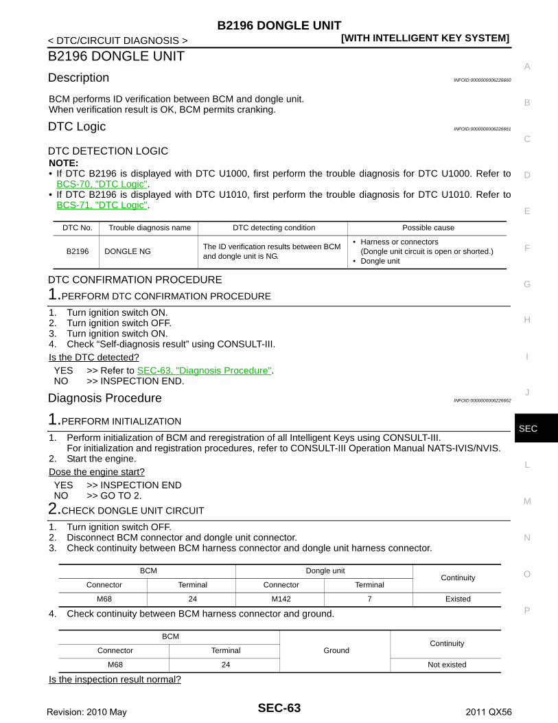
B2196 DONGLE UNIT[WITH INTELLIGENT KEY SYSTEM]
C
D
E
F
G
H
I
J
L
M
A
B
EC
N
O
P
< DTC/CIRCUIT DIAGNOSIS >
S
B2196 DONGLE UNIT
Description INFOID:0000000006226660
BCM performs ID verification between BCM and dongle unit.When verification result is OK, BCM permits cranking.
DTC Logic INFOID:0000000006226661
DTC DETECTION LOGICNOTE:• If DTC B2196 is displayed with DTC U1000, first perform the trouble diagnosis for DTC U1000. Refer to
BCS-70, "DTC Logic".• If DTC B2196 is displayed with DTC U1010, first perform the trouble diagnosis for DTC U1010. Refer to
BCS-71, "DTC Logic".
DTC CONFIRMATION PROCEDURE
1.PERFORM DTC CONFIRMATION PROCEDURE
1. Turn ignition switch ON.2. Turn ignition switch OFF.3. Turn ignition switch ON.4. Check “Self-diagnosis result” using CONSULT-III.Is the DTC detected?YES >> Refer to SEC-63, "Diagnosis Procedure".NO >> INSPECTION END.
Diagnosis Procedure INFOID:0000000006226662
1.PERFORM INITIALIZATION
1. Perform initialization of BCM and reregistration of all Intelligent Keys using CONSULT-III.For initialization and registration procedures, refer to CONSULT-III Operation Manual NATS-IVIS/NVIS.
2. Start the engine.Dose the engine start?YES >> INSPECTION ENDNO >> GO TO 2.
2.CHECK DONGLE UNIT CIRCUIT
1. Turn ignition switch OFF.2. Disconnect BCM connector and dongle unit connector.3. Check continuity between BCM harness connector and dongle unit harness connector.
4. Check continuity between BCM harness connector and ground.
Is the inspection result normal?
DTC No. Trouble diagnosis name DTC detecting condition Possible cause
B2196 DONGLE NGThe ID verification results between BCM and dongle unit is NG.
• Harness or connectors(Dongle unit circuit is open or shorted.)
• Dongle unit
BCM Dongle unitContinuity
Connector Terminal Connector Terminal
M68 24 M142 7 Existed
BCM
GroundContinuity
Connector Terminal
M68 24 Not existed
SEC-63Revision: 2010 May 2011 QX56

[WITH INTELLIGENT KEY SYSTEM]B2196 DONGLE UNIT
< DTC/CIRCUIT DIAGNOSIS >YES >> GO TO 3.NO >> Repair or replace harness.
3.CHECK DONGLE UNIT GROUND CIRCUIT
Check continuity between dongle unit harness connector and ground.
Is the inspection result normal?YES >> Replace dongle unit.NO >> Repair or replace harness.
Dongle unit
GroundContinuity
Connector Terminal
M142 1 Existed
SEC-64Revision: 2010 May 2011 QX56

B2198 NATS ANTENNA AMP.[WITH INTELLIGENT KEY SYSTEM]
C
D
E
F
G
H
I
J
L
M
A
B
EC
N
O
P
< DTC/CIRCUIT DIAGNOSIS >
S
B2198 NATS ANTENNA AMP.
DTC Logic INFOID:0000000006226216
DTC DETECTION LOGIC
DTC CONFIRMATION PROCEDURE
1.PERFORM DTC CONFIRMATION PROCEDURE 1
1. Contact Intelligent Key backside to push-button ignition switch.2. Check DTC in “Self Diagnostic Result” mode of “BCM” using CONSULT-III.Is DTC detected?YES >> Go to SEC-65, "Diagnosis Procedure".NO >> GO TO 2.
2.PERFORM DTC CONFIRMATION PROCEDURE 2
1. Press the push-button ignition switch.2. Check DTC in “Self Diagnostic Result” mode of “BCM” using CONSULT-III.Is DTC detected?YES >> Go to SEC-65, "Diagnosis Procedure".NO >> INSPECTION END
Diagnosis Procedure INFOID:0000000006226217
1.CHECK FUSE
1. Turn ignition switch OFF.2. Check that the following fuse in IPDM E/R is not blown.
Is the fuse fusing?YES >> Replace the blown fuse after repairing the cause of blowing.NO >> GO TO 2.
2.CHECK NATS ANTENNA AMP. POWER SUPPLY
1. Disconnect NATS antenna amp. connector.2. Check voltage between NATS antenna amp. harness connector and ground.
Is the inspection result normal?YES >> GO TO 4.NO >> GO TO 3.
3.CHECK NATS ANTENNA AMP. POWER SUPPLY CIRCUIT
1. Disconnect IPDM E/R connector.2. Check continuity between IPDM E/R harness connector and NATS antenna amp. connector.
DTC No. Trouble diagnosis name DTC detecting condition Possible cause
B2198 NATS ANTENNA AMP.Inactive communication between NATS antenna amp. and BCM
• Harness or connectors(NATS antenna amp. circuit is open or shorted.)
• NATS antenna amp.• IPDM E/R
Signal name Fuse No.
Battery power supply 43
(+)
(–)Voltage (V)(Approx.)
NATS antenna amp.
Connector Terminal
M26 1 Ground Battery voltage
SEC-65Revision: 2010 May 2011 QX56
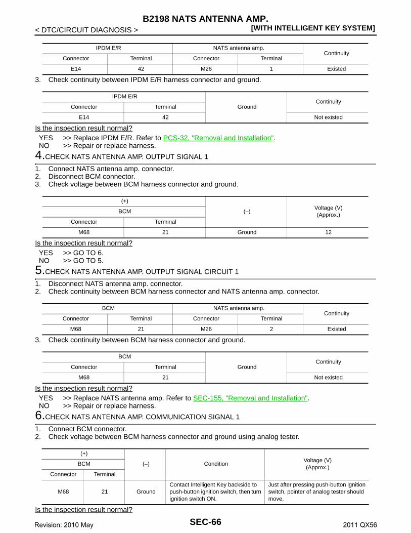
[WITH INTELLIGENT KEY SYSTEM]B2198 NATS ANTENNA AMP.
< DTC/CIRCUIT DIAGNOSIS >
3. Check continuity between IPDM E/R harness connector and ground.
Is the inspection result normal?YES >> Replace IPDM E/R. Refer to PCS-32, "Removal and Installation".NO >> Repair or replace harness.
4.CHECK NATS ANTENNA AMP. OUTPUT SIGNAL 1
1. Connect NATS antenna amp. connector.2. Disconnect BCM connector.3. Check voltage between BCM harness connector and ground.
Is the inspection result normal?YES >> GO TO 6.NO >> GO TO 5.
5.CHECK NATS ANTENNA AMP. OUTPUT SIGNAL CIRCUIT 1
1. Disconnect NATS antenna amp. connector.2. Check continuity between BCM harness connector and NATS antenna amp. connector.
3. Check continuity between BCM harness connector and ground.
Is the inspection result normal?YES >> Replace NATS antenna amp. Refer to SEC-155, "Removal and Installation".NO >> Repair or replace harness.
6.CHECK NATS ANTENNA AMP. COMMUNICATION SIGNAL 1
1. Connect BCM connector.2. Check voltage between BCM harness connector and ground using analog tester.
Is the inspection result normal?
IPDM E/R NATS antenna amp.Continuity
Connector Terminal Connector Terminal
E14 42 M26 1 Existed
IPDM E/R
GroundContinuity
Connector Terminal
E14 42 Not existed
(+)
(–)Voltage (V)(Approx.)
BCM
Connector Terminal
M68 21 Ground 12
BCM NATS antenna amp.Continuity
Connector Terminal Connector Terminal
M68 21 M26 2 Existed
BCM
GroundContinuity
Connector Terminal
M68 21 Not existed
(+)
(–) ConditionVoltage (V)(Approx.)
BCM
Connector Terminal
M68 21 GroundContact Intelligent Key backside to push-button ignition switch, then turn ignition switch ON.
Just after pressing push-button ignition switch, pointer of analog tester should move.
SEC-66Revision: 2010 May 2011 QX56

B2198 NATS ANTENNA AMP.[WITH INTELLIGENT KEY SYSTEM]
C
D
E
F
G
H
I
J
L
M
A
B
EC
N
O
P
< DTC/CIRCUIT DIAGNOSIS >
S
YES >> GO TO 7.NO >> Replace NATS antenna amp. Refer to SEC-155, "Removal and Installation".
7.CHECK NATS ANTENNA AMP. OUTPUT SIGNAL 2
1. Disconnect BCM connector.2. Check voltage between BCM harness connector and ground.
Is the inspection result normal?YES >> GO TO 9.NO >> GO TO 8.
8.CHECK NATS ANTENNA AMP. OUTPUT SIGNAL CIRCUIT 2
1. Disconnect NATS antenna amp. connector.2. Check continuity between BCM harness connector and NATS antenna amp. connector.
3. Check continuity between BCM harness connector and ground.
Is the inspection result normal?YES >> Replace NATS antenna amp. Refer to SEC-155, "Removal and Installation".NO >> Repair or replace harness.
9.CHECK NATS ANTENNA AMP. COMMUNICATION SIGNAL 2
1. Connect BCM connector.2. Check voltage between BCM harness connector and ground using analog tester.
Is the inspection result normal?YES >> GO TO 10.NO >> Replace NATS antenna amp. Refer to SEC-155, "Removal and Installation".
10.CHECK NATS ANTENNA AMP. GROUND CIRCUIT
1. Disconnect NATS antenna amp. connector.2. Check continuity between NATS antenna amp. harness connector and ground.
Is the inspection result normal?
(+)
(–)Voltage (V)(Approx.)
BCM
Connector Terminal
M68 25 Ground 12
BCM NATS antenna amp.Continuity
Connector Terminal Connector Terminal
M68 25 M26 3 Existed
BCM
GroundContinuity
Connector Terminal
M68 25 Not existed
(+)
(–) ConditionVoltage (V)(Approx.)
BCM
Connector Terminal
M68 25 GroundContact Intelligent Key backside to push-button ignition switch, then turn ignition switch ON.
Just after pressing push-button ignition switch, pointer of analog tester should move.
NATS antenna amp.
GroundContinuity
Connector Terminal
M26 4 Existed
SEC-67Revision: 2010 May 2011 QX56

[WITH INTELLIGENT KEY SYSTEM]B2198 NATS ANTENNA AMP.
< DTC/CIRCUIT DIAGNOSIS >YES >> GO TO 11.NO >> Repair or replace harness.
11.CHECK INTERMITTENT INCIDENT
Refer to GI-40, "Intermittent Incident".
>> INSPECTION END
SEC-68Revision: 2010 May 2011 QX56
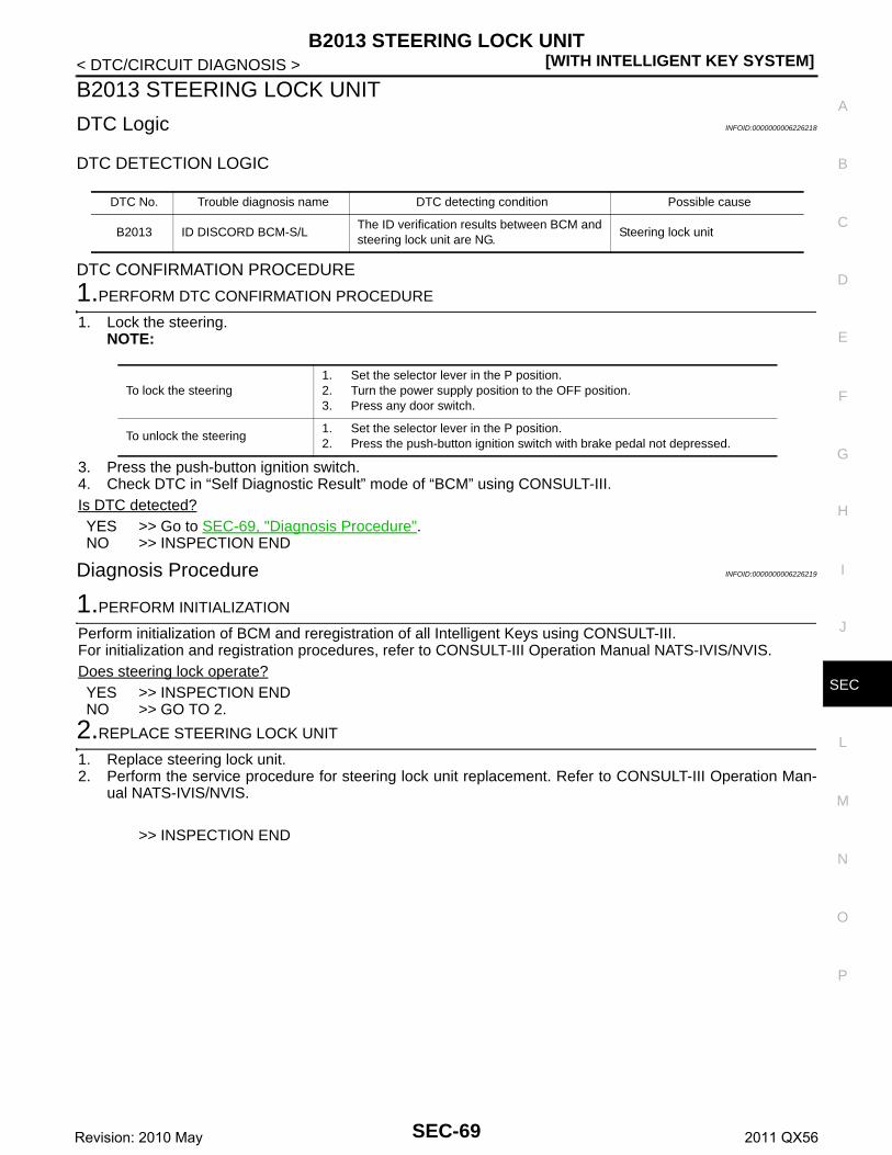
B2013 STEERING LOCK UNIT[WITH INTELLIGENT KEY SYSTEM]
C
D
E
F
G
H
I
J
L
M
A
B
EC
N
O
P
< DTC/CIRCUIT DIAGNOSIS >
S
B2013 STEERING LOCK UNIT
DTC Logic INFOID:0000000006226218
DTC DETECTION LOGIC
DTC CONFIRMATION PROCEDURE
1.PERFORM DTC CONFIRMATION PROCEDURE
1. Lock the steering.NOTE:
3. Press the push-button ignition switch.4. Check DTC in “Self Diagnostic Result” mode of “BCM” using CONSULT-III.Is DTC detected?YES >> Go to SEC-69, "Diagnosis Procedure".NO >> INSPECTION END
Diagnosis Procedure INFOID:0000000006226219
1.PERFORM INITIALIZATION
Perform initialization of BCM and reregistration of all Intelligent Keys using CONSULT-III.For initialization and registration procedures, refer to CONSULT-III Operation Manual NATS-IVIS/NVIS.Does steering lock operate?YES >> INSPECTION ENDNO >> GO TO 2.
2.REPLACE STEERING LOCK UNIT
1. Replace steering lock unit.2. Perform the service procedure for steering lock unit replacement. Refer to CONSULT-III Operation Man-
ual NATS-IVIS/NVIS.
>> INSPECTION END
DTC No. Trouble diagnosis name DTC detecting condition Possible cause
B2013 ID DISCORD BCM-S/LThe ID verification results between BCM and steering lock unit are NG.
Steering lock unit
To lock the steering1. Set the selector lever in the P position.2. Turn the power supply position to the OFF position.3. Press any door switch.
To unlock the steering1. Set the selector lever in the P position.2. Press the push-button ignition switch with brake pedal not depressed.
SEC-69Revision: 2010 May 2011 QX56

[WITH INTELLIGENT KEY SYSTEM]B2014 CHAIN OF STRG-IMMU
< DTC/CIRCUIT DIAGNOSIS >
B2014 CHAIN OF STRG-IMMU
DTC Logic INFOID:0000000006226220
DTC DETECTION LOGIC
DTC CONFIRMATION PROCEDURE
1.PERFORM DTC CONFIRMATION PROCEDURE
1. Lock steering.NOTE:
3. Press the push-button ignition switch.4. Check DTC in “Self Diagnostic Result” mode of “BCM” using CONSULT-III.Is DTC detected?YES >> Go to SEC-70, "Diagnosis Procedure".NO >> INSPECTION END
Diagnosis Procedure INFOID:0000000006226221
1.CHECK STEERING LOCK UNIT POWER SUPPLY
1. Turn ignition switch OFF.2. Disconnect steering lock unit connector.3. Check voltage between steering lock unit harness connector and ground.
Is the inspection result normal?YES >> GO TO 3.NO >> GO TO 2.
2.CHECK STEERING LOCK UNIT POWER SUPPLY CIRCUIT
1. Disconnect BCM connector.2. Check continuity between steering lock unit harness connector and BCM harness connector.
3. Check continuity between steering lock unit harness connector and ground.
DTC No. Trouble diagnosis name DTC detecting condition Possible cause
B2014 CHAIN OF S/L-BCMInactive communication between steering lock unit and BCM
• Harness or connectors(Steering lock unit circuit is open or shorted.)
• Steering lock unit• BCM
To lock the steering1. Set the selector lever in the P position.2. Turn the power supply position to the OFF position.3. Press any door switch.
To unlock the steering1. Set the selector lever in the P position.2. Press the push-button ignition switch with brake pedal not depressed.
(+)
(–) ConditionVoltage (V)(Approx.)
Steering lock unit
Connector Terminal
M12 7 Ground Ignition switchOFF or ACC 12
ON 0
Steering lock unit BCMContinuity
Connector Terminal Connector Terminal
M12 7 M71 95 Existed
SEC-70Revision: 2010 May 2011 QX56

B2014 CHAIN OF STRG-IMMU[WITH INTELLIGENT KEY SYSTEM]
C
D
E
F
G
H
I
J
L
M
A
B
EC
N
O
P
< DTC/CIRCUIT DIAGNOSIS >
S
Is the inspection result normal?YES >> GO TO 7.NO >> Repair or replace harness.
3.CHECK STEERING LOCK UNIT GROUND CIRCUIT
Check continuity between steering lock unit and ground.
Is the inspection result normal?YES >> GO TO 4.NO >> Repair or replace harness.
4.CHECK STEERING LOCK UNIT COMMUNICATION SIGNAL
1. Connect steering lock unit connector and BCM connector.2. Read voltage signal between steering lock unit harness connector and ground.
NOTE:
Is the inspection result normal?YES >> GO TO 5.NO >> GO TO 6.
5.REPLACE STEERING LOCK UNIT
1. Replace steering lock unit.2. Perform the service procedure for steering lock unit replacement. Refer to CONSULT-III Operation Man-
ual NATS-IVIS/NVIS.
Steering lock unit
GroundContinuity
Connector Terminal
M12 7 Not existed
Steering lock unit
Ground
ContinuityConnector Terminal
M125
Existed6
(+)
(–) ConditionVoltage (V)(Approx.)
Steering lock unit
Connector Terminal
M12 2 Ground Steering lock unit
Lock status 12
Lock or unlock
For 15 seconds after unlock
12
15 seconds or later after unlock.
0
To lock the steering1. Set the selector lever in the P position.2. Turn the power supply position to the OFF position.3. Press any door switch.
To unlock the steering1. Set the selector lever in the P position.2. Press the push-button ignition switch with brake pedal not depressed.
JMKIA0066GB
SEC-71Revision: 2010 May 2011 QX56
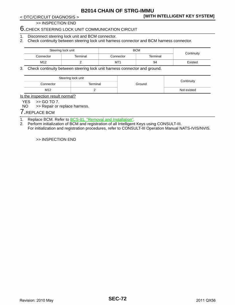
[WITH INTELLIGENT KEY SYSTEM]B2014 CHAIN OF STRG-IMMU
< DTC/CIRCUIT DIAGNOSIS >>> INSPECTION END
6.CHECK STEERING LOCK UNIT COMMUNICATION CIRCUIT
1. Disconnect steering lock unit and BCM connector.2. Check continuity between steering lock unit harness connector and BCM harness connector.
3. Check continuity between steering lock unit harness connector and ground.
Is the inspection result normal?YES >> GO TO 7.NO >> Repair or replace harness.
7.REPLACE BCM
1. Replace BCM. Refer to BCS-81, "Removal and Installation".2. Perform initialization of BCM and registration of all Intelligent Keys using CONSULT-III.
For initialization and registration procedures, refer to CONSULT-III Operation Manual NATS-IVIS/NVIS.
>> INSPECTION END
Steering lock unit BCMContinuity
Connector Terminal Connector Terminal
M12 2 M71 94 Existed
Steering lock unit
GroundContinuity
Connector Terminal
M12 2 Not existed
SEC-72Revision: 2010 May 2011 QX56
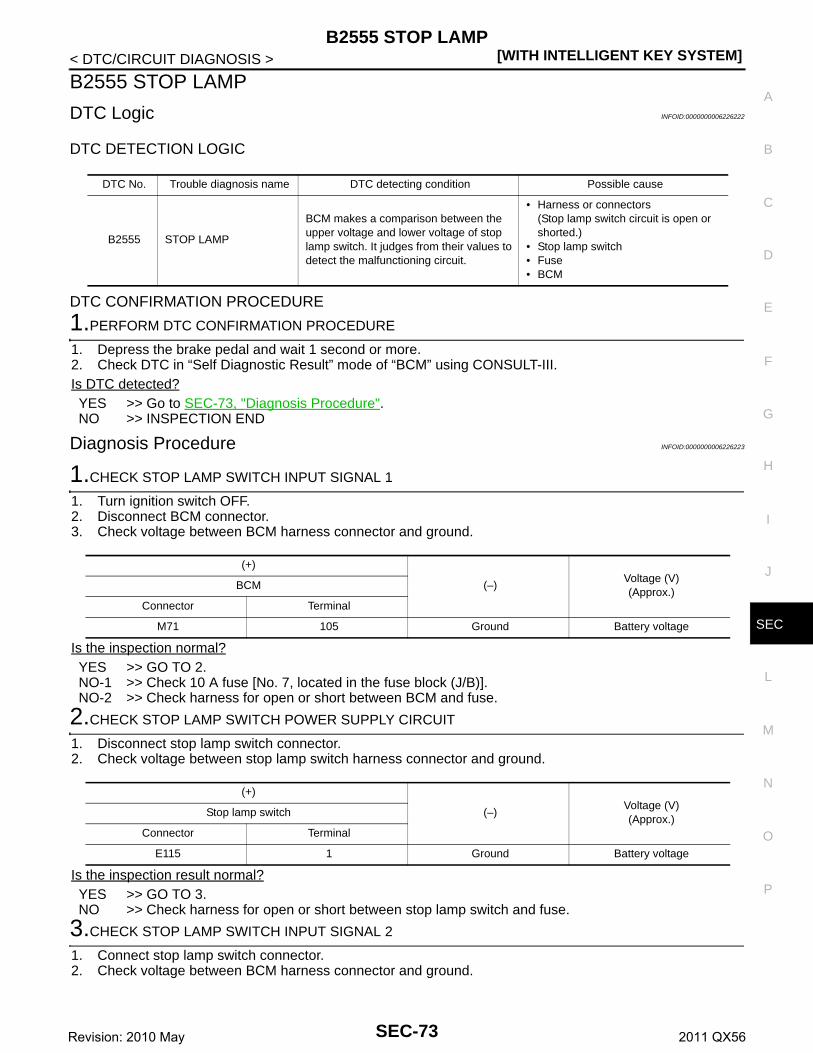
B2555 STOP LAMP[WITH INTELLIGENT KEY SYSTEM]
C
D
E
F
G
H
I
J
L
M
A
B
EC
N
O
P
< DTC/CIRCUIT DIAGNOSIS >
S
B2555 STOP LAMP
DTC Logic INFOID:0000000006226222
DTC DETECTION LOGIC
DTC CONFIRMATION PROCEDURE
1.PERFORM DTC CONFIRMATION PROCEDURE
1. Depress the brake pedal and wait 1 second or more.2. Check DTC in “Self Diagnostic Result” mode of “BCM” using CONSULT-III.Is DTC detected?YES >> Go to SEC-73, "Diagnosis Procedure".NO >> INSPECTION END
Diagnosis Procedure INFOID:0000000006226223
1.CHECK STOP LAMP SWITCH INPUT SIGNAL 1
1. Turn ignition switch OFF.2. Disconnect BCM connector.3. Check voltage between BCM harness connector and ground.
Is the inspection normal?YES >> GO TO 2.NO-1 >> Check 10 A fuse [No. 7, located in the fuse block (J/B)].NO-2 >> Check harness for open or short between BCM and fuse.
2.CHECK STOP LAMP SWITCH POWER SUPPLY CIRCUIT
1. Disconnect stop lamp switch connector.2. Check voltage between stop lamp switch harness connector and ground.
Is the inspection result normal?YES >> GO TO 3.NO >> Check harness for open or short between stop lamp switch and fuse.
3.CHECK STOP LAMP SWITCH INPUT SIGNAL 2
1. Connect stop lamp switch connector.2. Check voltage between BCM harness connector and ground.
DTC No. Trouble diagnosis name DTC detecting condition Possible cause
B2555 STOP LAMP
BCM makes a comparison between the upper voltage and lower voltage of stop lamp switch. It judges from their values to detect the malfunctioning circuit.
• Harness or connectors(Stop lamp switch circuit is open or shorted.)
• Stop lamp switch• Fuse• BCM
(+)
(–)Voltage (V)(Approx.)
BCM
Connector Terminal
M71 105 Ground Battery voltage
(+)
(–)Voltage (V)(Approx.)
Stop lamp switch
Connector Terminal
E115 1 Ground Battery voltage
SEC-73Revision: 2010 May 2011 QX56

[WITH INTELLIGENT KEY SYSTEM]B2555 STOP LAMP
< DTC/CIRCUIT DIAGNOSIS >
Is the inspecting result normal?YES >> GO TO 4.NO >> GO TO 5.
4.REPLACE BCM
1. Replace BCM. Refer to BCS-81, "Removal and Installation".2. Perform initialization of BCM and registration of all Intelligent Keys using CONSULT-III.
For initialization and registration procedures, refer to CONSULT-III Operation Manual NATS-IVIS/NVIS.
>> INSPECTION END
5.CHECK STOP LAMP SWITCH CIRCUIT
1. Disconnect stop lamp switch connector.2. Check continuity between stop lamp switch harness connector and BCM harness connector.
3. Check continuity between stop lamp switch harness connector and ground.
Is the inspection result normal?YES >> GO TO 6.NO >> Repair or replace harness.
6.CHECK STOP LAMP SWITCH
Refer to SEC-74, "Component Inspection".Is the inspection result normal?YES >> GO TO 7.NO >> Replace stop lamp switch. Refer to BR-20, "Removal and Installation".
7.CHECK INTERMITTENT INCIDENT
Refer to GI-40, "Intermittent Incident".
>> INSPECTION END
Component Inspection INFOID:0000000006226224
1.CHECK STOP LAMP SWITCH
1. Turn ignition switch OFF.2. Disconnect stop lamp switch connector.3. Check continuity between stop lamp switch terminals.
(+)
(–) ConditionVoltage (V)(Approx.)
BCM
Connector Terminal
M68 9 Ground Brake pedalDepressed Battery voltage
Not depressed 0
Stop lamp switch BCMContinuity
Connector Terminal Connector Terminal
E115 2 M68 9 Existed
Stop lamp switch
GroundContinuity
Connector Terminal
E115 2 Not existed
SEC-74Revision: 2010 May 2011 QX56

B2555 STOP LAMP[WITH INTELLIGENT KEY SYSTEM]
C
D
E
F
G
H
I
J
L
M
A
B
EC
N
O
P
< DTC/CIRCUIT DIAGNOSIS >
S
Is the inspection result normal?YES >> INSPECTION ENDNO >> Replace stop lamp switch. Refer to BR-20, "Removal and Installation".
Stop lamp switchCondition Continuity
Terminal
1 2 Brake pedalNot depressed Not existed
Depressed Existed
SEC-75Revision: 2010 May 2011 QX56

[WITH INTELLIGENT KEY SYSTEM]B2556 PUSH-BUTTON IGNITION SWITCH
< DTC/CIRCUIT DIAGNOSIS >
B2556 PUSH-BUTTON IGNITION SWITCH
DTC Logic INFOID:0000000006226225
DTC DETECTION LOGIC
DTC CONFIRMATION PROCEDURE
1.PERFORM DTC CONFIRMATION PROCEDURE
1. Press push-button ignition switch under the following condition.- Brake pedal: Not depressed2. Release push-button ignition switch and wait 100 seconds or more. 3. Check DTC in “Self Diagnostic Result” mode of “BCM” using CONSULT-III.Is DTC detected?YES >> Go to SEC-76, "Diagnosis Procedure".NO >> INSPECTION END
Diagnosis Procedure INFOID:0000000006226226
1.CHECK PUSH-BUTTON IGNITION SWITCH INPUT SIGNAL
1. Turn ignition switch OFF.2. Disconnect push-button ignition switch connector.3. Check voltage between push-button ignition switch harness connector and ground.
Is the inspection result normal?YES >> GO TO 4.NO >> GO TO 2.
2.CHECK PUSH-BUTTON IGNITION SWITCH CIRCUIT
1. Disconnect BCM connector and IPDM E/R connector.2. Check continuity between push-button ignition switch harness connector and BCM harness connector.
3. Check continuity between push-button ignition switch harness connector and ground.
Is the inspection result normal?YES >> GO TO 3.NO >> Repair or replace harness.
DTC No. Trouble diagnosis name DTC detecting condition Possible cause
B2556 PUSH-BTN IGN SWBCM detects the push-button ignition switch stuck at ON for 100 seconds or more.
• Harness or connectors(Push-button ignition switch circuit is shorted.)
• Push-button ignition switch• BCM
(+)
(–)Voltage (V)(Approx.)
Push-button ignition switch
Connector Terminal
M101 4 Ground 12
Push-button ignition switch BCMContinuity
Connector Terminal Connector Terminal
M101 4 M71 100 Existed
Push-button ignition switch
GroundContinuity
Connector Terminal
M101 4 Not existed
SEC-76Revision: 2010 May 2011 QX56

B2556 PUSH-BUTTON IGNITION SWITCH[WITH INTELLIGENT KEY SYSTEM]
C
D
E
F
G
H
I
J
L
M
A
B
EC
N
O
P
< DTC/CIRCUIT DIAGNOSIS >
S
3.REPLACE BCM
1. Replace BCM. Refer to BCS-81, "Removal and Installation".2. Perform initialization of BCM and registration of all Intelligent Keys using CONSULT-III.
For initialization and registration procedures, refer to CONSULT-III Operation Manual NATS-IVIS/NVIS.
>> INSPECTION END
4.CHECK PUSH-BUTTON IGNITION SWITCH GROUND CIRCUIT
Check continuity between push-button ignition switch harness connector and ground.
Is the inspection result normal?YES >> GO TO 5.NO >> Repair or replace harness.
5.CHECK PUSH-BUTTON IGNITION SWITCH
Refer to SEC-77, "Component Inspection".Is the inspection result normal?YES >> GO TO 6.NO >> Replace push-button ignition switch. Refer to SEC-156, "Removal and Installation".
6.CHECK INTERMITTENT INCIDENT
Refer to GI-40, "Intermittent Incident".
>> INSPECTION END
Component Inspection INFOID:0000000006226227
1.CHECK PUSH-BUTTON IGNITION SWITCH
1. Turn ignition switch OFF.2. Disconnect push-button ignition switch connector.3. Check continuity between push-button ignition switch terminals.
Is the inspection result normal?YES >> INSPECTION ENDNO >> Replace push-button ignition switch. Refer to SEC-156, "Removal and Installation".
Push-button ignition switch
GroundContinuity
Connector Terminal
M101 1 Existed
Push-button ignition switchCondition Continuity
Terminal
1 4Push-button ignition switch
Pressed Existed
Not pressed Not existed
SEC-77Revision: 2010 May 2011 QX56

[WITH INTELLIGENT KEY SYSTEM]B2557 VEHICLE SPEED
< DTC/CIRCUIT DIAGNOSIS >
B2557 VEHICLE SPEED
DTC Logic INFOID:0000000006226228
DTC DETECTION LOGICNOTE:• If DTC B2557 is displayed with DTC U1000, first perform the trouble diagnosis for DTC U1000. Refer to
BCS-70, "DTC Logic".• If DTC B2557 is displayed with DTC U1010, first perform the trouble diagnosis for DTC U1010. Refer to
BCS-71, "DTC Logic".
DTC CONFIRMATION PROCEDURE
1.PERFORM DTC CONFIRMATION PROCEDURE
1. Start engine and wait 10 seconds or more.2. Drive the vehicle at a vehicle speed of 10 km/h (6.2 MPH) or more for 10 seconds or more.3. Check DTC in “Self Diagnostic Result” mode of “BCM” using CONSULT-III.Is DTC detected?YES >> Go to SEC-78, "Diagnosis Procedure".NO >> INSPECTION END
Diagnosis Procedure INFOID:0000000006226229
1.CHECK DTC OF “ABS ACTUATOR AND ELECTRIC UNIT (CONTROL UNIT)”
Check DTC in “Self Diagnostic Result” mode of “ABS” using CONSULT-III.Is DTC detected?YES >> Perform the trouble diagnosis related to the detected DTC. Refer to BRC-51, "DTC Index".NO >> GO TO 2.
2.CHECK DTC OF “COMBINATION METER”
Check DTC in “Self Diagnostic Result” mode of “METER/M&A” using CONSULT-III.Is DTC detected?YES >> Perform the trouble diagnosis related to the detected DTC. Refer to MWI-43, "DTC Index".NO >> GO TO 3.
3.CHECK INTERMITTENT INCIDENT
Refer to GI-40, "Intermittent Incident".
>> INSPECTION END
DTC No. Trouble diagnosis name DTC detecting condition Possible causes
B2557 VEHICLE SPEED
BCM detects one of the following conditions for 10 seconds continuously.• Vehicle speed signal from combination meter is 10
km/h (6.2 MPH) or more, and vehicle speed signal from ABS actuator and electric unit (control unit) is 4 km/h (2.5 MPH) or less.
• Vehicle speed signal from combination meter is 4 km/h (2.5 MPH) or less, and vehicle speed signal from ABS actuator and electric unit (control unit) is 10 km/h (6.2 MPH) or more.
• Harness or connectors(The CAN communication line is open or shorted.)
• Combination meter• ABS actuator and electric unit
(control unit)
SEC-78Revision: 2010 May 2011 QX56
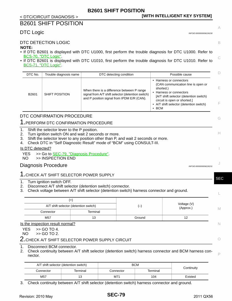
B2601 SHIFT POSITION[WITH INTELLIGENT KEY SYSTEM]
C
D
E
F
G
H
I
J
L
M
A
B
EC
N
O
P
< DTC/CIRCUIT DIAGNOSIS >
S
B2601 SHIFT POSITION
DTC Logic INFOID:0000000006226230
DTC DETECTION LOGICNOTE:• If DTC B2601 is displayed with DTC U1000, first perform the trouble diagnosis for DTC U1000. Refer to
BCS-70, "DTC Logic".• If DTC B2601 is displayed with DTC U1010, first perform the trouble diagnosis for DTC U1010. Refer to
BCS-71, "DTC Logic".
DTC CONFIRMATION PROCEDURE
1.PERFORM DTC CONFIRMATION PROCEDURE
1. Shift the selector lever to the P position.2. Turn ignition switch ON and wait 2 seconds or more.3. Shift the selector lever to any position other than P, and wait 2 seconds or more.4. Check DTC in “Self Diagnostic Result” mode of “BCM” using CONSULT-III.Is DTC detected?YES >> Go to SEC-79, "Diagnosis Procedure".NO >> INSPECTION END
Diagnosis Procedure INFOID:0000000006226231
1.CHECK A/T SHIFT SELECTOR POWER SUPPLY
1. Turn ignition switch OFF.2. Disconnect A/T shift selector (detention switch) connector.3. Check voltage between A/T shift selector (detention switch) harness connector and ground.
Is the inspection result normal?YES >> GO TO 4.NO >> GO TO 2.
2.CHECK A/T SHIFT SELECTOR POWER SUPPLY CIRCUIT
1. Disconnect BCM connector.2. Check continuity between A/T shift selector (detention switch) harness connector and BCM harness con-
nector.
3. Check continuity between A/T shift selector (detention switch) harness connector and ground.
DTC No. Trouble diagnosis name DTC detecting condition Possible cause
B2601 SHIFT POSITIONWhen there is a difference between P range signal from A/T shift selector (detention switch) and P position signal from IPDM E/R (CAN).
• Harness or connectors(CAN communication line is open or shorted.)
• Harness or connectors[A/T shift selector (detention switch) circuit is open or shorted.]
• A/T shift selector (detention switch)• BCM
(+)
(–)Voltage (V)(Approx.)
A/T shift selector (detention switch)
Connector Terminal
M57 13 Ground 12
A/T shift selector (detention switch) BCMContinuity
Connector Terminal Connector Terminal
M57 13 M71 104 Existed
SEC-79Revision: 2010 May 2011 QX56

[WITH INTELLIGENT KEY SYSTEM]B2601 SHIFT POSITION
< DTC/CIRCUIT DIAGNOSIS >
Is the inspection result normal?YES >> GO TO 3.NO >> Repair or replace harness.
3.REPLACE BCM
1. Replace BCM. Refer to BCS-81, "Removal and Installation".2. Perform initialization of BCM and registration of all Intelligent Keys using CONSULT-III.
For initialization and registration procedures, refer to CONSULT-III Operation Manual NATS-IVIS/NVIS.
>> INSPECTION END
4.CHECK A/T SHIFT SELECTOR CIRCUIT (BCM)
1. Disconnect BCM connector and IPDM E/R connector.2. Check continuity between A/T shift selector (detention switch) harness connector and BCM harness con-
nector.
3. Check continuity between A/T shift selector (detention switch) harness connector and ground.
Is the inspection result normal?YES >> GO TO 5.NO >> Repair or replace harness.
5.CHECK A/T SHIFT SELECTOR CIRCUIT (IPDM E/R)
Check continuity between A/T shift selector (detention switch) harness connector and IPDM E/R harness con-nector.
Is the inspection result normal?YES >> GO TO 6.NO >> Repair or replace harness.
6.CHECK A/T SHIFT SELECTOR (DETENTION SWITCH)
Refer to SEC-81, "Component Inspection".Is the inspection result normal?YES >> GO TO 7.NO >> Replace A/T shift selector. Refer to TM-176, "Removal and Installation".
7.CHECK INTERMITTENT INCIDENT
Refer to GI-40, "Intermittent Incident".
>> INSPECTION END
A/T shift selector (detention switch)
GroundContinuity
Connector Terminal
M57 13 Not existed
A/T shift selector (detention switch) BCMContinuity
Connector Terminal Connector Terminal
M57 14 M68 37 Existed
A/T shift selector (detention switch)
GroundContinuity
Connector Terminal
M57 14 Not existed
A/T shift selector (detention switch) IPDM E/RContinuity
Connector Terminal Connector Terminal
M57 14 E17 64 Existed
SEC-80Revision: 2010 May 2011 QX56

B2601 SHIFT POSITION[WITH INTELLIGENT KEY SYSTEM]
C
D
E
F
G
H
I
J
L
M
A
B
EC
N
O
P
< DTC/CIRCUIT DIAGNOSIS >
S
Component Inspection INFOID:0000000006226232
1.CHECK A/T SHIFT SELECTOR (DETENTION SWITCH)
1. Turn ignition switch OFF.2. Disconnect A/T shift selector connector.3. Check continuity between A/T shift selector (detention switch) terminals.
Is the inspection result normal?YES >> INSPECTION ENDNO >> Replace A/T shift selector. Refer to TM-176, "Removal and Installation".
A/T shift selector (detention switch)Condition Continuity
Terminal
13 14 Selector leverP position Not existed
Other than above Existed
SEC-81Revision: 2010 May 2011 QX56

[WITH INTELLIGENT KEY SYSTEM]B2602 SHIFT POSITION
< DTC/CIRCUIT DIAGNOSIS >
B2602 SHIFT POSITION
DTC Logic INFOID:0000000006226233
DTC DETECTION LOGICNOTE:• If DTC B2602 is displayed with DTC U1000, first perform the trouble diagnosis for DTC U1000. Refer to
BCS-70, "DTC Logic".• If DTC B2602 is displayed with DTC U1010, first perform the trouble diagnosis for DTC U1010. Refer to
BCS-71, "DTC Logic".
DTC CONFIRMATION PROCEDURE
1.PERFORM DTC CONFIRMATION PROCEDURE
1. Start engine.2. Drive vehicle at a speed of 4 km/h (2.5 MPH) or more for 10 seconds or more.3. Check DTC in “Self Diagnostic Result” mode of “BCM” using CONSULT-III.Is DTC detected?YES >> Go to SEC-82, "Diagnosis Procedure".NO >> INSPECTION END
Diagnosis Procedure INFOID:0000000006226234
1.CHECK DTC OF COMBINATION METER
Check DTC in “Self Diagnostic Result” mode of “METER/M&A” using CONSULT-III.Is DTC detected?YES >> Perform the trouble diagnosis related to the detected DTC. Refer to MWI-43, "DTC Index".NO >> GO TO 2.
2.CHECK A/T SHIFT SELECTOR POWER SUPPLY
1. Turn ignition switch OFF.2. Disconnect A/T shift selector (detention switch) connector.3. Check voltage between A/T shift selector (detention switch) harness connector and ground.
Is the inspection result normal?YES >> GO TO 5.NO >> GO TO 3.
3.CHECK A/T SHIFT SELECTOR POWER SUPPLY CIRCUIT
1. Disconnect BCM connector.2. Check continuity between A/T shift selector (detention switch) harness connector and BCM harness con-
nector.
DTC No. Trouble diagnosis name DTC detecting condition Possible cause
B2602 SHIFT POSITION
BCM detects the following status for 10 seconds.• Selector lever is in the P position• Vehicle speed is 4 km/h (2.5 MPH) or more• Ignition switch is in the ON position
• Harness or connectors(CAN communication line is open or shorted.)
• Harness or connectors[A/T shift selector (detention switch) circuit is open or shorted.]
• A/T shift selector (detention switch)• Combination meter• BCM
(+)
(–)Voltage (V)(Approx.)
A/T shift selector (detention switch)
Connector Terminal
M57 13 Ground 12
SEC-82Revision: 2010 May 2011 QX56

B2602 SHIFT POSITION[WITH INTELLIGENT KEY SYSTEM]
C
D
E
F
G
H
I
J
L
M
A
B
EC
N
O
P
< DTC/CIRCUIT DIAGNOSIS >
S
3. Check continuity between A/T shift selector (detention switch) harness connector and ground.
Is the inspection result normal?YES >> GO TO 4.NO >> Repair or replace harness.
4.REPLACE BCM
1. Replace BCM. Refer to BCS-81, "Removal and Installation".2. Perform initialization of BCM and registration of all Intelligent Keys using CONSULT-III.
For initialization and registration procedures, refer to CONSULT-III Operation Manual NATS-IVIS/NVIS.
>> INSPECTION END
5.CHECK A/T SHIFT SELECTOR CIRCUIT
1. Disconnect BCM connector and IPDM E/R connector.2. Check continuity between A/T shift selector (detention switch) harness connector and BCM harness con-
nector.
3. Check continuity between A/T shift selector (detention switch) harness connector and ground.
Is the inspection result normal?YES >> GO TO 6.NO >> Repair or replace harness.
6.CHECK A/T SHIFT SELECTOR (DETENTION SWITCH)
Refer to SEC-83, "Component Inspection".Is the inspection result normal?YES >> GO TO 7.NO >> Replace A/T shift selector. Refer to TM-176, "Removal and Installation".
7.CHECK INTERMITTENT INCIDENT
Refer to GI-40, "Intermittent Incident".
>> INSPECTION END
Component Inspection INFOID:0000000006226235
1.CHECK A/T SHIFT SELECTOR (DETENTION SWITCH)
1. Turn ignition switch OFF.2. Disconnect A/T shift selector connector.3. Check continuity between A/T shift selector (detention switch) terminals.
A/T shift selector (detention switch) BCMContinuity
Connector Terminal Connector Terminal
M57 13 M71 104 Existed
A/T shift selector (detention switch)
GroundContinuity
Connector Terminal
M57 13 Not existed
A/T shift selector (detention switch) BCMContinuity
Connector Terminal Connector Terminal
M57 14 M68 37 Existed
A/T shift selector (detention switch)
GroundContinuity
Connector Terminal
M57 14 Not existed
SEC-83Revision: 2010 May 2011 QX56
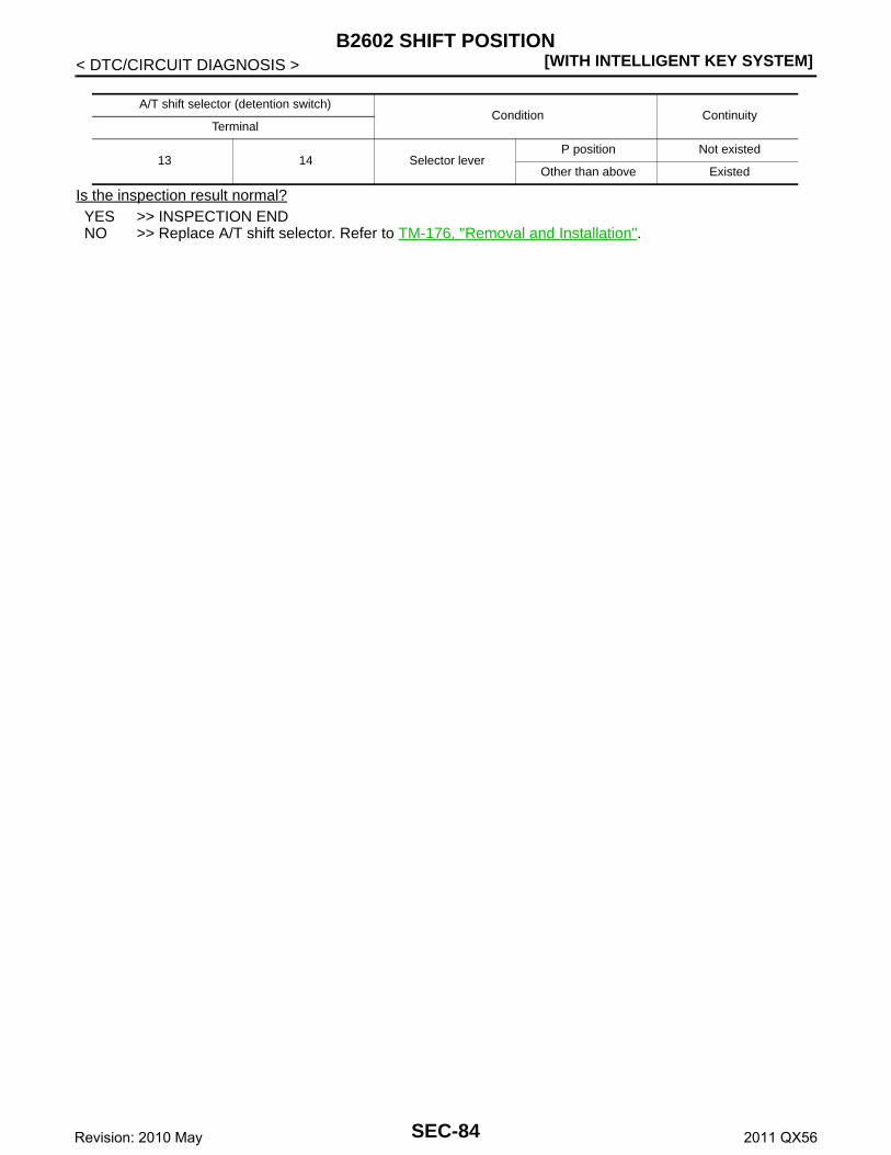
[WITH INTELLIGENT KEY SYSTEM]B2602 SHIFT POSITION
< DTC/CIRCUIT DIAGNOSIS >
Is the inspection result normal?YES >> INSPECTION ENDNO >> Replace A/T shift selector. Refer to TM-176, "Removal and Installation".
A/T shift selector (detention switch)Condition Continuity
Terminal
13 14 Selector leverP position Not existed
Other than above Existed
SEC-84Revision: 2010 May 2011 QX56

B2603 SHIFT POSITION[WITH INTELLIGENT KEY SYSTEM]
C
D
E
F
G
H
I
J
L
M
A
B
EC
N
O
P
< DTC/CIRCUIT DIAGNOSIS >
S
B2603 SHIFT POSITION
DTC Logic INFOID:0000000006226236
DTC DETECTION LOGICNOTE:• If DTC B2603 is displayed with DTC B2601, first perform the trouble diagnosis for DTC B2601. Refer to
SEC-79, "DTC Logic".
DTC CONFIRMATION PROCEDURE
1.PERFORM DTC CONFIRMATION PROCEDURE 1
1. Shift the selector lever to the P position.2. Turn ignition switch ON and wait 1 second or more.3. Check DTC in “Self Diagnostic Result” mode of “BCM” using CONSULT-III.Is DTC detected?YES >> Go to SEC-85, "Diagnosis Procedure".NO >> GO TO 2.
2.PERFORM DTC CONFIRMATION PROCEDURE 2
1. Shift the selector lever to any position other than P, and wait 1 second or more.2. Check DTC in “Self Diagnostic Result” mode of “BCM” using CONSULT-III.Is DTC detected?YES >> Go to SEC-85, "Diagnosis Procedure".NO >> INSPECTION END
Diagnosis Procedure INFOID:0000000006226237
1.INSPECTION START
Perform inspection in accordance with procedure that confirms DTC.Which procedure confirms DTC?DTC confirmation procedure 1>>GO TO 2.DTC confirmation procedure 2>>GO TO 6.
2.CHECK DTC OF TCM
Check DTC in “Self Diagnostic Result” mode of “TCM” using CONSULT-III.Is DTC detected?YES >> Perform the trouble diagnosis related to the detected DTC. Refer to TM-78, "DTC Index".NO >> GO TO 3.
3.CHECK BCM INPUT SIGNAL
1. Turn ignition switch ON.2. Check voltage between BCM harness connector and ground.
DTC No. Trouble diagnosis name DTC detecting condition Possible causes
B2603 SHIFT POSI STATUS
BCM detects the following status when ignition switch is in the ON position.• P position signal from TCM: approx. 0 V• A/T shift selector (detention switch) signal:
approx. 0 V
• Harness or connector[A/T shift selector (detention switch) circuit is open or shorted.]
• Harness or connectors(TCM circuit is open or shorted.)
• A/T shift selector (detention switch)• A/T assembly (TCM)• BCM
SEC-85Revision: 2010 May 2011 QX56
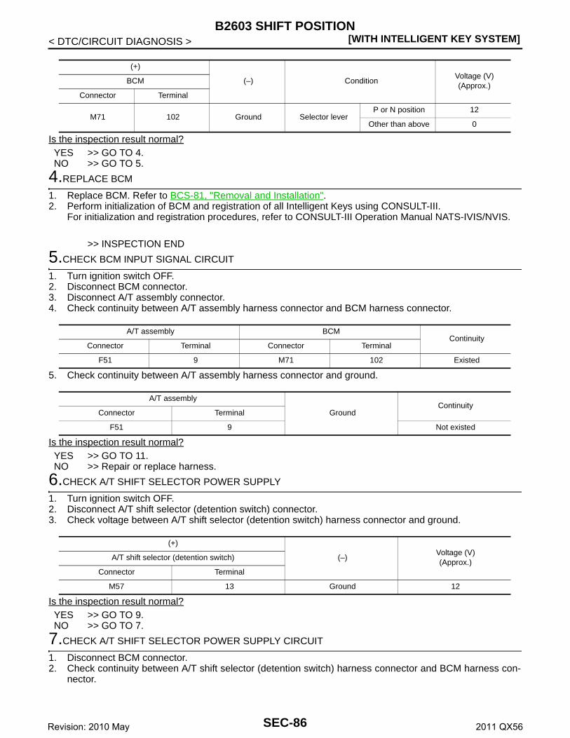
[WITH INTELLIGENT KEY SYSTEM]B2603 SHIFT POSITION
< DTC/CIRCUIT DIAGNOSIS >
Is the inspection result normal?YES >> GO TO 4.NO >> GO TO 5.
4.REPLACE BCM
1. Replace BCM. Refer to BCS-81, "Removal and Installation".2. Perform initialization of BCM and registration of all Intelligent Keys using CONSULT-III.
For initialization and registration procedures, refer to CONSULT-III Operation Manual NATS-IVIS/NVIS.
>> INSPECTION END
5.CHECK BCM INPUT SIGNAL CIRCUIT
1. Turn ignition switch OFF.2. Disconnect BCM connector.3. Disconnect A/T assembly connector.4. Check continuity between A/T assembly harness connector and BCM harness connector.
5. Check continuity between A/T assembly harness connector and ground.
Is the inspection result normal?YES >> GO TO 11.NO >> Repair or replace harness.
6.CHECK A/T SHIFT SELECTOR POWER SUPPLY
1. Turn ignition switch OFF.2. Disconnect A/T shift selector (detention switch) connector.3. Check voltage between A/T shift selector (detention switch) harness connector and ground.
Is the inspection result normal?YES >> GO TO 9.NO >> GO TO 7.
7.CHECK A/T SHIFT SELECTOR POWER SUPPLY CIRCUIT
1. Disconnect BCM connector.2. Check continuity between A/T shift selector (detention switch) harness connector and BCM harness con-
nector.
(+)
(–) ConditionVoltage (V)(Approx.)
BCM
Connector Terminal
M71 102 Ground Selector leverP or N position 12
Other than above 0
A/T assembly BCMContinuity
Connector Terminal Connector Terminal
F51 9 M71 102 Existed
A/T assembly
GroundContinuity
Connector Terminal
F51 9 Not existed
(+)
(–)Voltage (V)(Approx.)
A/T shift selector (detention switch)
Connector Terminal
M57 13 Ground 12
SEC-86Revision: 2010 May 2011 QX56
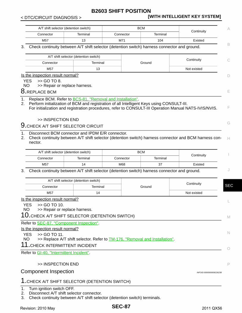
B2603 SHIFT POSITION[WITH INTELLIGENT KEY SYSTEM]
C
D
E
F
G
H
I
J
L
M
A
B
EC
N
O
P
< DTC/CIRCUIT DIAGNOSIS >
S
3. Check continuity between A/T shift selector (detention switch) harness connector and ground.
Is the inspection result normal?YES >> GO TO 8.NO >> Repair or replace harness.
8.REPLACE BCM
1. Replace BCM. Refer to BCS-81, "Removal and Installation".2. Perform initialization of BCM and registration of all Intelligent Keys using CONSULT-III.
For initialization and registration procedures, refer to CONSULT-III Operation Manual NATS-IVIS/NVIS.
>> INSPECTION END
9.CHECK A/T SHIFT SELECTOR CIRCUIT
1. Disconnect BCM connector and IPDM E/R connector.2. Check continuity between A/T shift selector (detention switch) harness connector and BCM harness con-
nector.
3. Check continuity between A/T shift selector (detention switch) harness connector and ground.
Is the inspection result normal?YES >> GO TO 10.NO >> Repair or replace harness.
10.CHECK A/T SHIFT SELECTOR (DETENTION SWITCH)
Refer to SEC-87, "Component Inspection".Is the inspection result normal?YES >> GO TO 11.NO >> Replace A/T shift selector. Refer to TM-176, "Removal and Installation".
11.CHECK INTERMITTENT INCIDENT
Refer to GI-40, "Intermittent Incident".
>> INSPECTION END
Component Inspection INFOID:0000000006226238
1.CHECK A/T SHIFT SELECTOR (DETENTION SWITCH)
1. Turn ignition switch OFF.2. Disconnect A/T shift selector connector.3. Check continuity between A/T shift selector (detention switch) terminals.
A/T shift selector (detention switch) BCMContinuity
Connector Terminal Connector Terminal
M57 13 M71 104 Existed
A/T shift selector (detention switch)
GroundContinuity
Connector Terminal
M57 13 Not existed
A/T shift selector (detention switch) BCMContinuity
Connector Terminal Connector Terminal
M57 14 M68 37 Existed
A/T shift selector (detention switch)
GroundContinuity
Connector Terminal
M57 14 Not existed
SEC-87Revision: 2010 May 2011 QX56

[WITH INTELLIGENT KEY SYSTEM]B2603 SHIFT POSITION
< DTC/CIRCUIT DIAGNOSIS >
Is the inspection result normal?YES >> INSPECTION ENDNO >> Replace A/T shift selector. Refer to TM-176, "Removal and Installation".
A/T shift selector (detention switch)Condition Continuity
Terminal
13 14 Selector leverP position Not existed
Other than above Existed
SEC-88Revision: 2010 May 2011 QX56

B2604 SHIFT POSITION[WITH INTELLIGENT KEY SYSTEM]
C
D
E
F
G
H
I
J
L
M
A
B
EC
N
O
P
< DTC/CIRCUIT DIAGNOSIS >
S
B2604 SHIFT POSITION
DTC Logic INFOID:0000000006226239
DTC DETECTION LOGICNOTE:• If DTC B2604 is displayed with DTC U1000, first perform the trouble diagnosis for DTC U1000. Refer to
BCS-70, "DTC Logic".• If DTC B2604 is displayed with DTC U1010, first perform the trouble diagnosis for DTC U1010. Refer to
BCS-71, "DTC Logic".
DTC CONFIRMATION PROCEDURE
1.PERFORM DTC CONFIRMATION PROCEDURE
1. Shift the selector lever to the P position.2. Turn ignition switch ON and wait 5 seconds or more.3. Shift the selector lever to the N position and wait 5 seconds or more.4. Shift the selector lever to any position other than P and N, and wait 5 seconds or more.5. Check DTC in “Self Diagnostic Result” mode of “BCM” using CONSULT-III.Is DTC detected?YES >> Go to SEC-89, "Diagnosis Procedure".NO >> INSPECTION END
Diagnosis Procedure INFOID:0000000006226240
1.CHECK DTC OF TCM
Check DTC in “Self Diagnostic Result” mode of “TCM” using CONSULT-III.Is DTC detected?YES >> Perform the trouble diagnosis related to the detected DTC. Refer to TM-78, "DTC Index".NO >> GO TO 2.
2.CHECK BCM INPUT SIGNAL
1. Turn ignition switch ON.2. Check voltage between BCM harness connector and ground.
Is the inspection result normal?YES >> GO TO 3.NO >> GO TO 4.
3.REPLACE BCM
1. Replace BCM. Refer to BCS-81, "Removal and Installation".2. Perform initialization of BCM and registration of all Intelligent Keys using CONSULT-III.
DTC No. Trouble diagnosis name DTC detecting condition Possible cause
B2604 PNP/CLUTCH SW
The following states are detected for 5 seconds while ignition switch is ON.• P/N position signal is sent from TCM but shift
position signal input (CAN) from TCM is other than P and N
• P/N position signal is not sent from TCM but shift position signal input (CAN) from TCM is P or N
• Harness or connectors(CAN communication line is open or shorted.)
• Harness or connectors(TCM circuit is open or shorted.)
• TCM• BCM
(+)
(–) ConditionVoltage (V)(Approx.)
BCM
Connector Terminal
M71 102 Ground Selector leverP or N position 12
Other than above 0
SEC-89Revision: 2010 May 2011 QX56

[WITH INTELLIGENT KEY SYSTEM]B2604 SHIFT POSITION
< DTC/CIRCUIT DIAGNOSIS >For initialization and registration procedures, refer to CONSULT-III Operation Manual NATS-IVIS/NVIS.
>> INSPECTION END
4.CHECK BCM INPUT SIGNAL CIRCUIT
1. Turn ignition switch OFF.2. Disconnect A/T assembly connector.3. Disconnect BCM connector.4. Check continuity between A/T assembly harness connector and BCM harness connector.
5. Check continuity between A/T assembly harness connector and ground.
Is the inspection result normal?YES >> GO TO 5.NO >> Repair or replace harness.
5.CHECK INTERMITTENT INCIDENT
Refer to GI-40, "Intermittent Incident".
>> INSPECTION END
A/T assembly BCMContinuity
Connector Terminal Connector Terminal
F51 9 M71 102 Existed
A/T assembly
GroundContinuity
Connector Terminal
F51 9 Not existed
SEC-90Revision: 2010 May 2011 QX56

B2605 SHIFT POSITION[WITH INTELLIGENT KEY SYSTEM]
C
D
E
F
G
H
I
J
L
M
A
B
EC
N
O
P
< DTC/CIRCUIT DIAGNOSIS >
S
B2605 SHIFT POSITION
DTC Logic INFOID:0000000006226241
DTC DETECTION LOGICNOTE:• If DTC B2605 is displayed with DTC U1000, first perform the trouble diagnosis for DTC U1000. Refer to
BCS-70, "DTC Logic".• If DTC B2605 is displayed with DTC U1010, first perform the trouble diagnosis for DTC U1010. Refer to
BCS-71, "DTC Logic".
DTC CONFIRMATION PROCEDURE
1.PERFORM DTC CONFIRMATION PROCEDURE
1. Shift the selector lever to the P position.2. Turn ignition switch ON and wait 1 second or more.3. Shift the selector lever to the N position and wait 1 second or more.4. Shift the selector lever to any position other than P and N, and wait 1 second or more.5. Check DTC in “Self Diagnostic Result” mode of “BCM” using CONSULT-III.Is DTC detected?YES >> Go to SEC-91, "Diagnosis Procedure".NO >> INSPECTION END
Diagnosis Procedure INFOID:0000000006226242
1.CHECK IPDM E/R INPUT SIGNAL
1. Turn ignition switch OFF.2. Disconnect IPDM E/R connector.3. Turn ignition switch ON.4. Check voltage between IPDM E/R harness connector and ground.
Is the inspection result normal?YES >> Replace IPDM E/R. Refer to PCS-32, "Removal and Installation".NO >> GO TO 2.
2.CHECK IPDM E/R INPUT SIGNAL CIRCUIT
1. Turn ignition switch OFF.2. Disconnect BCM connector.3. Check continuity between IPDM E/R harness connector and BCM harness connector.
DTC No. Trouble diagnosis name DTC detecting condition Possible cause
B2605 PNP/CLUTCH SW
When ignition switch is ON, P/N position signal input from TCM and P/N position signal (CAN) input from IPDM E/R do not match.
• Harness or connectors(CAN communication line is open or shorted.)
• Harness or connectors(TCM circuit is open or shorted.)
• IPDM E/R• BCM
(+)
(–) ConditionVoltage (V)(Approx.)
IPDM E/R
Connector Terminal
E15 48 Ground Selector leverP or N position 12
Other than above 0
IPDM E/R BCMContinuity
Connector Terminal Connector Terminal
E15 48 M71 102 Existed
SEC-91Revision: 2010 May 2011 QX56

[WITH INTELLIGENT KEY SYSTEM]B2605 SHIFT POSITION
< DTC/CIRCUIT DIAGNOSIS >4. Check continuity between IPDM E/R harness connector and ground.
Is the inspection result normal?YES >> GO TO 3.NO >> Repair or replace harness.
3.REPLACE BCM
1. Replace BCM. Refer to BCS-81, "Removal and Installation".2. Perform initialization of BCM and registration of all Intelligent Keys using CONSULT-III.
For initialization and registration procedures, refer to CONSULT-III Operation Manual NATS-IVIS/NVIS.
>> INSPECTION END
IPDM E/R
GroundContinuity
Connector Terminal
E15 48 Not existed
SEC-92Revision: 2010 May 2011 QX56
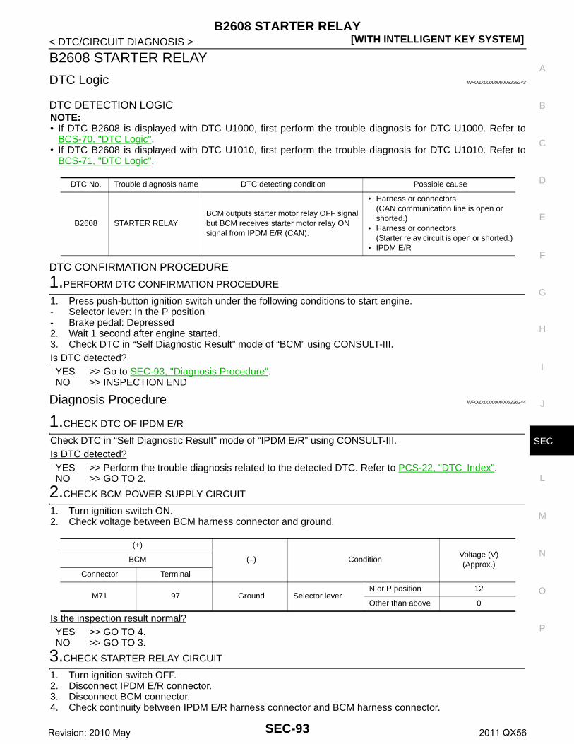
B2608 STARTER RELAY[WITH INTELLIGENT KEY SYSTEM]
C
D
E
F
G
H
I
J
L
M
A
B
EC
N
O
P
< DTC/CIRCUIT DIAGNOSIS >
S
B2608 STARTER RELAY
DTC Logic INFOID:0000000006226243
DTC DETECTION LOGICNOTE:• If DTC B2608 is displayed with DTC U1000, first perform the trouble diagnosis for DTC U1000. Refer to
BCS-70, "DTC Logic".• If DTC B2608 is displayed with DTC U1010, first perform the trouble diagnosis for DTC U1010. Refer to
BCS-71, "DTC Logic".
DTC CONFIRMATION PROCEDURE
1.PERFORM DTC CONFIRMATION PROCEDURE
1. Press push-button ignition switch under the following conditions to start engine.- Selector lever: In the P position- Brake pedal: Depressed2. Wait 1 second after engine started.3. Check DTC in “Self Diagnostic Result” mode of “BCM” using CONSULT-III.Is DTC detected?YES >> Go to SEC-93, "Diagnosis Procedure".NO >> INSPECTION END
Diagnosis Procedure INFOID:0000000006226244
1.CHECK DTC OF IPDM E/R
Check DTC in “Self Diagnostic Result” mode of “IPDM E/R” using CONSULT-III.Is DTC detected?YES >> Perform the trouble diagnosis related to the detected DTC. Refer to PCS-22, "DTC Index".NO >> GO TO 2.
2.CHECK BCM POWER SUPPLY CIRCUIT
1. Turn ignition switch ON.2. Check voltage between BCM harness connector and ground.
Is the inspection result normal?YES >> GO TO 4.NO >> GO TO 3.
3.CHECK STARTER RELAY CIRCUIT
1. Turn ignition switch OFF.2. Disconnect IPDM E/R connector.3. Disconnect BCM connector.4. Check continuity between IPDM E/R harness connector and BCM harness connector.
DTC No. Trouble diagnosis name DTC detecting condition Possible cause
B2608 STARTER RELAYBCM outputs starter motor relay OFF signal but BCM receives starter motor relay ON signal from IPDM E/R (CAN).
• Harness or connectors (CAN communication line is open or shorted.)
• Harness or connectors (Starter relay circuit is open or shorted.)
• IPDM E/R
(+)
(–) ConditionVoltage (V)(Approx.)
BCM
Connector Terminal
M71 97 Ground Selector leverN or P position 12
Other than above 0
SEC-93Revision: 2010 May 2011 QX56
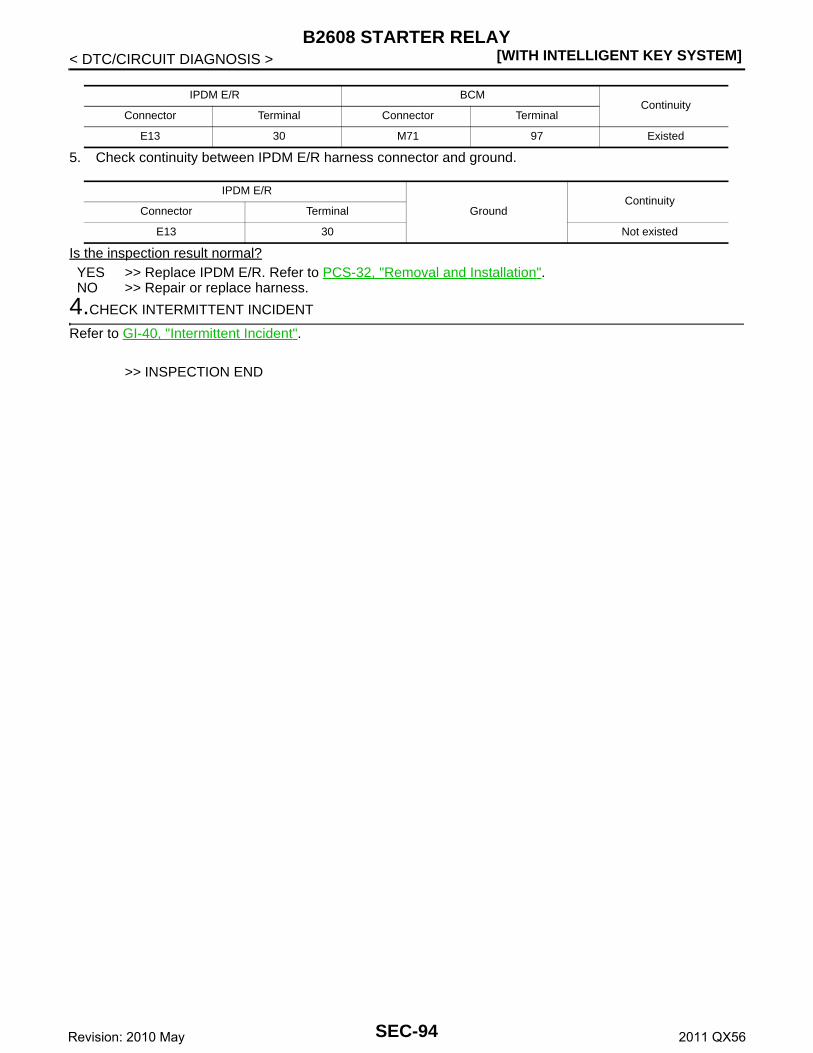
[WITH INTELLIGENT KEY SYSTEM]B2608 STARTER RELAY
< DTC/CIRCUIT DIAGNOSIS >
5. Check continuity between IPDM E/R harness connector and ground.
Is the inspection result normal?YES >> Replace IPDM E/R. Refer to PCS-32, "Removal and Installation".NO >> Repair or replace harness.
4.CHECK INTERMITTENT INCIDENT
Refer to GI-40, "Intermittent Incident".
>> INSPECTION END
IPDM E/R BCMContinuity
Connector Terminal Connector Terminal
E13 30 M71 97 Existed
IPDM E/R
GroundContinuity
Connector Terminal
E13 30 Not existed
SEC-94Revision: 2010 May 2011 QX56

B2609 STEERING STATUS[WITH INTELLIGENT KEY SYSTEM]
C
D
E
F
G
H
I
J
L
M
A
B
EC
N
O
P
< DTC/CIRCUIT DIAGNOSIS >
S
B2609 STEERING STATUS
DTC Logic INFOID:0000000006226245
DTC DETECTION LOGIC
DTC CONFIRMATION PROCEDURE
1.PERFORM DTC CONFIRMATION PROCEDURE 1
1. Press push-button ignition switch under the following conditions and wait 1 second or more.- Selector lever: In the P position- Brake pedal: Not depressed2. Check DTC in “Self Diagnostic Result” mode of “BCM” using CONSULT-III.Is DTC detected?YES >> Go to SEC-95, "Diagnosis Procedure".NO >> GO TO 2.
2.PERFORM DTC CONFIRMATION PROCEDURE 2
1. Turn ignition switch ON.2. Turn ignition switch OFF.3. Press driver side door switch and wait 1 second or more.4. Check DTC in “Self Diagnostic Result” mode of “BCM” using CONSULT-III.Is DTC detected?YES >> Go to SEC-95, "Diagnosis Procedure".NO >> INSPECTION END
Diagnosis Procedure INFOID:0000000006226246
1.CHECK IPDM E/R INPUT SIGNAL
1. Turn ignition switch OFF.2. Check voltage between IPDM E/R harness connector and ground.
NOTE:
Is the inspection result normal?YES >> GO TO 4.
DTC No. Trouble diagnosis name DTC detecting condition Possible cause
B2609 S/L STATUS
BCM detects one of the following status.• Combination of steering lock state switch and
steering unlock state switch is not normal.• Combination of steering lock state switch and
steering unlock state switch is different from steering lock/unlock state that BCM recognizes.
• Harness or connectors(Steering lock unit circuit is open or shorted.)
• Steering lock unit • BCM
(+)
(–) ConditionVoltage (V)(Approx.)
IPDM E/R
Connector Terminal
E17
63
Ground Steering lock unit
Lock 12
Unlock 0
65Lock 0
Unlock 12
To lock the steering1. Set the selector lever in the P position.2. Turn the power supply position to the OFF position.3. Press any door switch.
To unlock the steering1. Set the selector lever in the P position.2. Press the push-button ignition switch with brake pedal not depressed.
SEC-95Revision: 2010 May 2011 QX56
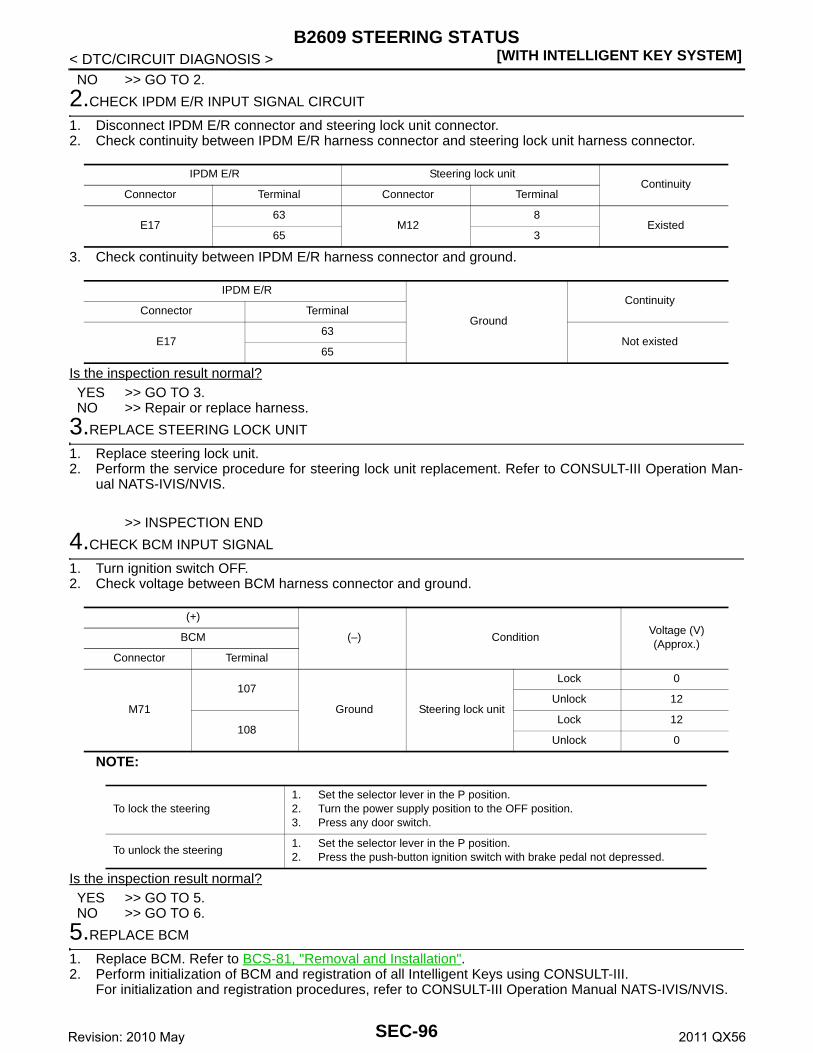
[WITH INTELLIGENT KEY SYSTEM]B2609 STEERING STATUS
< DTC/CIRCUIT DIAGNOSIS >NO >> GO TO 2.
2.CHECK IPDM E/R INPUT SIGNAL CIRCUIT
1. Disconnect IPDM E/R connector and steering lock unit connector.2. Check continuity between IPDM E/R harness connector and steering lock unit harness connector.
3. Check continuity between IPDM E/R harness connector and ground.
Is the inspection result normal?YES >> GO TO 3.NO >> Repair or replace harness.
3.REPLACE STEERING LOCK UNIT
1. Replace steering lock unit.2. Perform the service procedure for steering lock unit replacement. Refer to CONSULT-III Operation Man-
ual NATS-IVIS/NVIS.
>> INSPECTION END
4.CHECK BCM INPUT SIGNAL
1. Turn ignition switch OFF.2. Check voltage between BCM harness connector and ground.
NOTE:
Is the inspection result normal?YES >> GO TO 5.NO >> GO TO 6.
5.REPLACE BCM
1. Replace BCM. Refer to BCS-81, "Removal and Installation".2. Perform initialization of BCM and registration of all Intelligent Keys using CONSULT-III.
For initialization and registration procedures, refer to CONSULT-III Operation Manual NATS-IVIS/NVIS.
IPDM E/R Steering lock unitContinuity
Connector Terminal Connector Terminal
E1763
M128
Existed65 3
IPDM E/R
Ground
ContinuityConnector Terminal
E1763
Not existed65
(+)
(–) ConditionVoltage (V)(Approx.)
BCM
Connector Terminal
M71
107
Ground Steering lock unit
Lock 0
Unlock 12
108Lock 12
Unlock 0
To lock the steering1. Set the selector lever in the P position.2. Turn the power supply position to the OFF position.3. Press any door switch.
To unlock the steering1. Set the selector lever in the P position.2. Press the push-button ignition switch with brake pedal not depressed.
SEC-96Revision: 2010 May 2011 QX56

B2609 STEERING STATUS[WITH INTELLIGENT KEY SYSTEM]
C
D
E
F
G
H
I
J
L
M
A
B
EC
N
O
P
< DTC/CIRCUIT DIAGNOSIS >
S
>> INSPECTION END
6.CHECK BCM INPUT SIGNAL CIRCUIT
1. Disconnect BCM connector and steering lock unit connector.2. Check continuity between BCM harness connector and steering lock unit harness connector.
3. Check continuity between BCM harness connector and ground.
Is the inspection result normal?YES >> GO TO 7.NO >> Repair or replace harness.
7.REPLACE STEERING LOCK UNIT
1. Replace steering lock unit.2. Perform the service procedure for steering lock unit replacement. Refer to CONSULT-III Operation Man-
ual NATS-IVIS/NVIS.
>> INSPECTION END
BCM Steering lock unitContinuity
Connector Terminal Connector Terminal
M71107
M123
Existed108 8
BCM
Ground
ContinuityConnector Terminal
M71107
Not existed108
SEC-97Revision: 2010 May 2011 QX56

[WITH INTELLIGENT KEY SYSTEM]B260B STEERING LOCK UNIT
< DTC/CIRCUIT DIAGNOSIS >
B260B STEERING LOCK UNIT
DTC Logic INFOID:0000000006226247
DTC DETECTION LOGIC
DTC CONFIRMATION PROCEDURE
1.PERFORM DTC CONFIRMATION PROCEDURE
1. Turn ignition switch ON.2. Turn ignition switch OFF.3. Press driver side door switch.4. Shift selector lever to the P position.5. Press push-button ignition switch under the following condition.- Brake pedal: Not depressed6. Check DTC in “Self Diagnostic Result” mode of “BCM” using CONSULT-III.Is DTC detected?YES >> Go to SEC-98, "Diagnosis Procedure".NO >> INSPECTION END
Diagnosis Procedure INFOID:0000000006226248
1.INSPECTION START
1. Turn ignition switch ON.2. Select “Self Diagnostic Result” mode of “BCM” using CONSULT-III.3. Touch “ERASE”.4. Perform DTC CONFIRMATION PROCEDURE for DTC B260B. Refer to SEC-98, "DTC Logic".Is DTC detected?YES >> GO TO 2.NO >> INSPECTION END
2.REPLACE STEERING LOCK UNIT
1. Replace steering lock unit.2. Perform the service procedure for steering lock unit replacement. Refer to CONSULT-III Operation Man-
ual NATS-IVIS/NVIS.
>> INSPECTION END
DTC No. Trouble diagnosis name DTC detecting condition Possible cause
B260B STEERING LOCK UNITBCM detects malfunctioning of steering lock unit before steering unlocking.
Steering lock unit
SEC-98Revision: 2010 May 2011 QX56

B260C STEERING LOCK UNIT[WITH INTELLIGENT KEY SYSTEM]
C
D
E
F
G
H
I
J
L
M
A
B
EC
N
O
P
< DTC/CIRCUIT DIAGNOSIS >
S
B260C STEERING LOCK UNIT
DTC Logic INFOID:0000000006226249
DTC DETECTION LOGIC
DTC CONFIRMATION PROCEDURE
1.PERFORM DTC CONFIRMATION PROCEDURE
1. Shift selector lever to the P position.2. Press push-button ignition switch under the following condition.- Brake pedal: Not depressed3. Turn ignition switch ON.4. Turn ignition switch OFF.5. Press driver side door switch.6. Check DTC in “Self Diagnostic Result” mode of “BCM” using CONSULT-III.Is DTC detected?YES >> Go to SEC-99, "Diagnosis Procedure".NO >> INSPECTION END
Diagnosis Procedure INFOID:0000000006226250
1.INSPECTION START
1. Turn ignition switch ON.2. Select “Self Diagnostic Result” mode of “BCM” using CONSULT-III.3. Touch “ERASE”.4. Perform DTC CONFIRMATION PROCEDURE for DTC B260C. Refer to SEC-99, "DTC Logic".Is DTC detected?YES >> GO TO 2.NO >> INSPECTION END
2.REPLACE STEERING LOCK UNIT
1. Replace steering lock unit.2. Perform the service procedure for steering lock unit replacement. Refer to CONSULT-III Operation Man-
ual NATS-IVIS/NVIS.
>> INSPECTION END
DTC No. Trouble diagnosis name DTC detecting condition Possible cause
B260C STEERING LOCK UNITBCM detects malfunctioning of steering lock unit before steering locking.
Steering lock unit
SEC-99Revision: 2010 May 2011 QX56

[WITH INTELLIGENT KEY SYSTEM]B260D STEERING LOCK UNIT
< DTC/CIRCUIT DIAGNOSIS >
B260D STEERING LOCK UNIT
DTC Logic INFOID:0000000006226251
DTC DETECTION LOGIC
DTC CONFIRMATION PROCEDURE
1.PERFORM DTC CONFIRMATION PROCEDURE
1. Shift selector lever to the P position.2. Press push-button ignition switch under the following condition.- Brake pedal: Not depressed3. Turn ignition switch ON.4. Turn ignition switch OFF.5. Press driver side door switch.6. Check DTC in “Self Diagnostic Result” mode of “BCM” using CONSULT-III.Is DTC detected?YES >> Go to SEC-100, "Diagnosis Procedure".NO >> INSPECTION END
Diagnosis Procedure INFOID:0000000006226252
1.INSPECTION START
1. Turn ignition switch ON.2. Select “Self Diagnostic Result” mode of “BCM” using CONSULT-III.3. Touch “ERASE”.4. Perform DTC Confirmation Procedure for DTC B260D. Refer to SEC-100, "DTC Logic".Is DTC detected?YES >> GO TO 2.NO >> INSPECTION END
2.REPLACE STEERING LOCK UNIT
1. Replace steering lock unit.2. Perform the service procedure for steering lock unit replacement. Refer to CONSULT-III Operation Man-
ual NATS-IVIS/NVIS.
>> INSPECTION END
DTC No. Trouble diagnosis name DTC detecting condition Possible cause
B260D STEERING LOCK UNITBCM detects malfunctioning of steering lock unit after steering locking.
Steering lock unit
SEC-100Revision: 2010 May 2011 QX56

B260F ENGINE STATUS[WITH INTELLIGENT KEY SYSTEM]
C
D
E
F
G
H
I
J
L
M
A
B
EC
N
O
P
< DTC/CIRCUIT DIAGNOSIS >
S
B260F ENGINE STATUS
Description INFOID:0000000006226253
BCM receives the engine status signal from ECM via CAN communication.
DTC Logic INFOID:0000000006226254
DTC DETECTION LOGICNOTE:• If DTC B260F is displayed with DTC U1000, first perform the trouble diagnosis for DTC U1000. Refer to
BCS-70, "DTC Logic".• If DTC B260F is displayed with DTC U1010, first perform the trouble diagnosis for DTC U1010. Refer to
BCS-71, "DTC Logic".
DTC CONFIRMATION PROCEDURE
1.PERFORM DTC CONFIRMATION PROCEDURE
1. Turn ignition switch ON and wait 2 seconds or more.2. Check DTC in “Self Diagnostic Result” mode of “BCM” using CONSULT-III.Is DTC detected?YES >> Go to SEC-101, "Diagnosis Procedure".NO >> INSPECTION END
Diagnosis Procedure INFOID:0000000006226255
1.INSPECTION START
1. Turn ignition switch ON.2. Select “Self Diagnostic Result” mode of “BCM” using CONSULT-III.3. Touch “ERASE”.4. Perform DTC CONFIRMATION PROCEDURE for DTC B260F. Refer to SEC-101, "DTC Logic".Is DTC detected?YES >> GO TO 2.NO >> INSPECTION END
2.REPLACE ECM
1. Replace ECM. Refer to EC-535, "Removal and Installation".2. Perform “ADDITIONAL SERVICE WHEN REPLACING ECM”. Refer to EC-143, "Work Procedure".
>> INSPECTION END
DTC No. Trouble diagnosis name DTC detecting condition Possible cause
B260F ENG STATE SIG LOSTBCM has not yet received the engine status signal from ECM when ignition switch is in the ON position.
• Harness or connectors (CAN communication line is open or shorted.)
• ECM
SEC-101Revision: 2010 May 2011 QX56

[WITH INTELLIGENT KEY SYSTEM]B2612 STEERING STATUS
< DTC/CIRCUIT DIAGNOSIS >
B2612 STEERING STATUS
DTC Logic INFOID:0000000006226256
DTC DETECTION LOGICNOTE:• If DTC B2612 is displayed with DTC U1000, first perform the trouble diagnosis for DTC U1000. Refer to
BCS-70, "DTC Logic".• If DTC B2612 is displayed with DTC U1010, first perform the trouble diagnosis for DTC U1010. Refer to
BCS-71, "DTC Logic".
DTC CONFIRMATION PROCEDURE
1.PERFORM DTC CONFIRMATION PROCEDURE 1
1. Press push-button ignition switch under the following conditions and wait 1 second or more.- Selector lever: In the P position- Brake pedal: Not depressed2. Check DTC in “Self Diagnostic Result” mode of “BCM” using CONSULT-III.Is DTC detected?YES >> Go to SEC-102, "Diagnosis Procedure".NO >> GO TO 2.
2.PERFORM DTC CONFIRMATION PROCEDURE 2
1. Turn ignition switch ON.2. Turn ignition switch OFF.3. Press driver side door switch and wait 1 second or more.4. Check DTC in “Self Diagnostic Result” mode of “BCM” using CONSULT-III.Is DTC detected?YES >> Go to SEC-102, "Diagnosis Procedure".NO >> INSPECTION END
Diagnosis Procedure INFOID:0000000006226257
1.CHECK IPDM E/R INPUT SIGNAL
1. Turn ignition switch OFF.2. Check voltage between IPDM E/R harness connector and ground.
NOTE:
DTC No. Trouble diagnosis name DTC detecting condition Possible causes
B2612 S/L STATUSThe following 2 state signals are different.• Steering lock state recognition of BCM• Steering lock state signal from IPDM E/R
• Harness or connectors (CAN communication line is open or shorted.)
• Harness or connectors(Steering lock unit circuit is open or shorted.)
• Steering lock unit • IPDM E/R• BCM
(+)
(–) ConditionVoltage (V)(Approx.)
IPDM E/R
Connector Terminal
E17
63
Ground Steering lock unit
Lock 12
Unlock 0
65Lock 0
Unlock 12
SEC-102Revision: 2010 May 2011 QX56
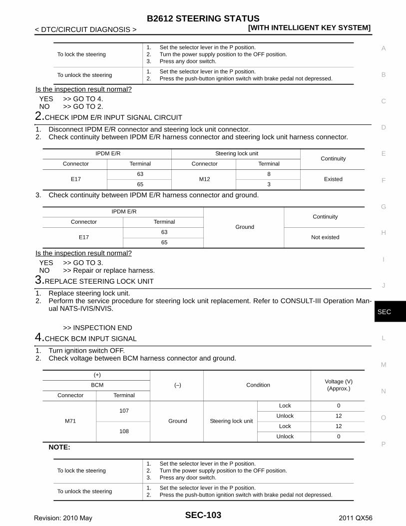
B2612 STEERING STATUS[WITH INTELLIGENT KEY SYSTEM]
C
D
E
F
G
H
I
J
L
M
A
B
EC
N
O
P
< DTC/CIRCUIT DIAGNOSIS >
S
Is the inspection result normal?YES >> GO TO 4.NO >> GO TO 2.
2.CHECK IPDM E/R INPUT SIGNAL CIRCUIT
1. Disconnect IPDM E/R connector and steering lock unit connector.2. Check continuity between IPDM E/R harness connector and steering lock unit harness connector.
3. Check continuity between IPDM E/R harness connector and ground.
Is the inspection result normal?YES >> GO TO 3.NO >> Repair or replace harness.
3.REPLACE STEERING LOCK UNIT
1. Replace steering lock unit.2. Perform the service procedure for steering lock unit replacement. Refer to CONSULT-III Operation Man-
ual NATS-IVIS/NVIS.
>> INSPECTION END
4.CHECK BCM INPUT SIGNAL
1. Turn ignition switch OFF.2. Check voltage between BCM harness connector and ground.
NOTE:
To lock the steering1. Set the selector lever in the P position.2. Turn the power supply position to the OFF position.3. Press any door switch.
To unlock the steering1. Set the selector lever in the P position.2. Press the push-button ignition switch with brake pedal not depressed.
IPDM E/R Steering lock unitContinuity
Connector Terminal Connector Terminal
E1763
M128
Existed65 3
IPDM E/R
Ground
ContinuityConnector Terminal
E1763
Not existed65
(+)
(–) ConditionVoltage (V)(Approx.)
BCM
Connector Terminal
M71
107
Ground Steering lock unit
Lock 0
Unlock 12
108Lock 12
Unlock 0
To lock the steering1. Set the selector lever in the P position.2. Turn the power supply position to the OFF position.3. Press any door switch.
To unlock the steering1. Set the selector lever in the P position.2. Press the push-button ignition switch with brake pedal not depressed.
SEC-103Revision: 2010 May 2011 QX56

[WITH INTELLIGENT KEY SYSTEM]B2612 STEERING STATUS
< DTC/CIRCUIT DIAGNOSIS >Is the inspection result normal?YES >> GO TO 5.NO >> GO TO 6.
5.REPLACE BCM
1. Replace BCM. Refer to BCS-81, "Removal and Installation".2. Perform initialization of BCM and registration of all Intelligent Keys using CONSULT-III.
For initialization and registration procedures, refer to CONSULT-III Operation Manual NATS-IVIS/NVIS.
>> INSPECTION END
6.CHECK BCM INPUT SIGNAL CIRCUIT
1. Disconnect BCM connector and steering lock unit connector.2. Check continuity between BCM harness connector and steering lock unit harness connector.
3. Check continuity between BCM harness connector and ground.
Is the inspection result normal?YES >> GO TO 7.NO >> Repair or replace harness.
7.REPLACE STEERING LOCK UNIT
1. Replace steering lock unit.2. Perform the service procedure for steering lock unit replacement. Refer to CONSULT-III Operation Man-
ual NATS-IVIS/NVIS.
>> INSPECTION END
BCM Steering lock unitContinuity
Connector Terminal Connector Terminal
M71107
M123
Existed108 8
BCM
Ground
ContinuityConnector Terminal
M71107
Not existed108
SEC-104Revision: 2010 May 2011 QX56

B2619 BCM[WITH INTELLIGENT KEY SYSTEM]
C
D
E
F
G
H
I
J
L
M
A
B
EC
N
O
P
< DTC/CIRCUIT DIAGNOSIS >
S
B2619 BCM
DTC Logic INFOID:0000000006226258
DTC DETECTION LOGIC
DTC CONFIRMATION PROCEDURE
1.PERFORM DTC CONFIRMATION PROCEDURE
1. Press push-button ignition switch under the following conditions and wait 1 second or more.- Selector lever: In the P position- Brake pedal: Not depressed2. Check DTC in “Self Diagnostic Result” of “BCM” using CONSULT-III.Is DTC detected?YES >> Go to SEC-105, "Diagnosis Procedure".NO >> INSPECTION END
Diagnosis Procedure INFOID:0000000006226259
1.INSPECTION START
1. Turn ignition switch ON.2. Select “Self Diagnostic Result” mode of “BCM” using CONSULT-III.3. Touch “ERASE”.4. Perform DTC CONFIRMATION PROCEDURE for DTC B2619. Refer to SEC-105, "DTC Logic".Is DTC detected?YES >> GO TO 2.NO >> INSPECTION END
2.REPLACE BCM
1. Replace BCM. Refer to BCS-81, "Removal and Installation".2. Perform initialization of BCM and registration of all Intelligent Keys using CONSULT-III.
For initialization and registration procedures, refer to CONSULT-III Operation Manual NATS-IVIS/NVIS.
>> INSPECTION END
DTC No. Trouble diagnosis name DTC detecting condition Possible cause
B2619 BCMThere is a difference between power supply output to steering lock unit and steering lock unit F/B result.
BCM
SEC-105Revision: 2010 May 2011 QX56

[WITH INTELLIGENT KEY SYSTEM]B26E9 STEERING STATUS
< DTC/CIRCUIT DIAGNOSIS >
B26E9 STEERING STATUS
DTC Logic INFOID:0000000006226260
DTC DETECTION LOGIC
DTC CONFIRMATION PROCEDURE
1.PERFORM DTC CONFIRMATION PROCEDURE
1. Turn ignition switch ON.2. Turn ignition switch OFF.3. Press driver side door switch.4. Turn ignition switch ON.5. Check DTC in “Self Diagnostic Result” mode of “BCM” using CONSULT-III.Is DTC detected?YES >> Refer to SEC-106, "Diagnosis Procedure".NO >> INSPECTION END
Diagnosis Procedure INFOID:0000000006226261
1.INSPECTION START
1. Turn ignition switch ON.2. Select “Self Diagnostic Result” mode of “BCM” using CONSULT-III.3. Touch “ERASE”.4. Perform DTC CONFIRMATION PROCEDURE for DTC B26E9. Refer to SEC-106, "DTC Logic".Is DTC detected?YES >> GO TO 2.NO >> INSPECTION END
2.REPLACE STEERING LOCK UNIT
1. Replace steering lock unit.2. Perform the service procedure for steering lock unit replacement. Refer to CONSULT-III Operation Man-
ual NATS-IVIS/NVIS.
>> INSPECTION END
DTC No. Trouble diagnosis name DTC detecting condition Possible cause
B26E9 LOCK MALFUNCTIONBCM activates steering lock but steering state that BCM recognizes is unlock.
Steering lock unit
SEC-106Revision: 2010 May 2011 QX56

B26EF STEERING LOCK RELAY[WITH INTELLIGENT KEY SYSTEM]
C
D
E
F
G
H
I
J
L
M
A
B
EC
N
O
P
< DTC/CIRCUIT DIAGNOSIS >
S
B26EF STEERING LOCK RELAY
DTC Logic INFOID:0000000006226262
DTC DETECTION LOGICNOTE:• If DTC B26EF is displayed with DTC U1000, first perform the trouble diagnosis for DTC U1000. Refer to
BCS-70, "DTC Logic".• If DTC B26EF is displayed with DTC U1010, first perform the trouble diagnosis for DTC U1010. Refer to
BCS-71, "DTC Logic".
DTC CONFIRMATION PROCEDURE
1.PERFORM DTC CONFIRMATION PROCEDURE
1. Shift selector lever to the P position.2. Turn ignition switch ON.3. Turn ignition switch OFF.4. Press driver side door switch and wait 2 seconds or more.5. Check DTC in “Self Diagnostic Result” mode of “BCM” using CONSULT-III.Is DTC detected?YES >> Go to SEC-107, "Diagnosis Procedure".NO >> INSPECTION END
Diagnosis Procedure INFOID:0000000006226263
1.CHECK DTC OF IPDM E/R
Check DTC in “Self Diagnostic Result” mode of “IPDM E/R” using CONSULT-III.Is DTC detected?YES >> Perform the diagnosis procedure related to the detected DTC. Refer to PCS-22, "DTC Index".NO >> GO TO 2.
2.CHECK STEERING LOCK UNIT POWER SUPPLY
Check voltage between steering lock unit harness connector and ground.
NOTE:
DTC No. Trouble diagnosis name DTC detecting condition Possible cause
B26EF STRG LCK RELAY OFF
BCM requests IPDM E/R to turn steering lock relay ON, but BCM cannot receive steering lock relay ON state signal from IPDM E/R (CAN) within 2 seconds.
• Harness or connectors (CAN communication line is open or shorted.)
• Harness or connector(Steering lock unit circuit is open or shorted.)
• Steering lock unit• IPDM E/R
(+)
(–) ConditionVoltage (V)(Approx.)
Steering lock unit
Connector Terminal
M12 1 Ground
Ignition switch OFF
A few seconds after opening the driver door
Battery voltage
Ignition switch LOCK
Press the push-button ignition switch
Battery voltage
Ignition switch ACC or ON 0
SEC-107Revision: 2010 May 2011 QX56

[WITH INTELLIGENT KEY SYSTEM]B26EF STEERING LOCK RELAY
< DTC/CIRCUIT DIAGNOSIS >
Is the inspection normal?YES >> GO TO 3.NO >> GO TO 4.
3.REPLACE STEERING LOCK UNIT
1. Replace steering lock unit.2. Perform the service procedure for steering lock unit replacement. Refer to CONSULT-III Operation Man-
ual NATS-IVIS/NVIS.
>> INSPECTION END
4.CHECK STEERING LOCK RELAY CIRCUIT
1. Disconnect IPDM E/R connector and steering lock unit connector.2. Check continuity between IPDM E/R harness connector and steering lock unit harness connector.
3. Check continuity between IPDM E/R harness connector and ground.
Is the inspection result normal?YES >> Replace IPDM E/R. Refer to PCS-32, "Removal and Installation".NO >> Repair or replace harness.
To lock the steering1. Set the selector lever in the P position.2. Turn the power supply position to the OFF position.3. Press any door switch.
To unlock the steering1. Set the selector lever in the P position.2. Press the push-button ignition switch with brake pedal not depressed.
IPDM E/R Steering lock unitContinuity
Connector Terminal Connector Terminal
E14 46 M12 1 Existed
IPDM E/R
GroundContinuity
Connector Terminal
E14 46 Not existed
SEC-108Revision: 2010 May 2011 QX56

B26F0 STEERING LOCK RELAY[WITH INTELLIGENT KEY SYSTEM]
C
D
E
F
G
H
I
J
L
M
A
B
EC
N
O
P
< DTC/CIRCUIT DIAGNOSIS >
S
B26F0 STEERING LOCK RELAY
DTC Logic INFOID:0000000006226264
DTC DETECTION LOGICNOTE:• If DTC B26F0 is displayed with DTC U1000, first perform the trouble diagnosis for DTC U1000. Refer to
BCS-70, "DTC Logic".• If DTC B26F0 is displayed with DTC U1010, first perform the trouble diagnosis for DTC U1010. Refer to
BCS-71, "DTC Logic".
DTC CONFIRMATION PROCEDURE
1.PERFORM DTC CONFIRMATION PROCEDURE
1. Shift selector lever to the P position.2. Turn ignition switch ON.3. Turn ignition switch OFF.4. Press driver side door switch and wait 2 seconds or more.5. Check DTC in “Self Diagnostic Result” mode of “BCM” using CONSULT-III.Is DTC detected?YES >> Go to SEC-109, "Diagnosis Procedure".NO >> INSPECTION END
Diagnosis Procedure INFOID:0000000006226265
1.CHECK DTC OF IPDM E/R
Check DTC in “Self Diagnostic Result” mode of “IPDM E/R” using CONSULT-III.Is DTC detected?YES >> Perform the diagnosis procedure related to the detected DTC. Refer to PCS-22, "DTC Index".NO >> GO TO 2.
2.CHECK STEERING LOCK UNIT POWER SUPPLY
Check voltage between steering lock unit harness connector and ground.
NOTE:
DTC No. Trouble diagnosis name DTC detecting condition Possible cause
B26F0 STRG LCK RELAY ON
BCM requests IPDM E/R to turn steering lock relay OFF, but BCM cannot receive steering lock relay OFF state signal from IPDM E/R (CAN) within 2 seconds.
• Harness or connectors (CAN communication line is open or shorted.)
• Harness or connector(Steering lock unit circuit is open or shorted.)
• Steering lock unit• IPDM E/R
(+)
(–) ConditionVoltage (V)(Approx.)
Steering lock unit
Connector Terminal
M12 1 Ground
Ignition switch OFF
A few seconds after opening the driver door
Battery voltage
Ignition switch LOCK
Press the push-button ignition switch
Battery voltage
Ignition switch ACC or ON 0
SEC-109Revision: 2010 May 2011 QX56

[WITH INTELLIGENT KEY SYSTEM]B26F0 STEERING LOCK RELAY
< DTC/CIRCUIT DIAGNOSIS >
Is the inspection normal?YES >> GO TO 3.NO >> GO TO 4.
3.REPLACE STEERING LOCK UNIT
1. Replace steering lock unit.2. Perform the service procedure for steering lock unit replacement. Refer to CONSULT-III Operation Man-
ual NATS-IVIS/NVIS.
>> INSPECTION END
4.CHECK STEERING LOCK RELAY CIRCUIT
1. Disconnect IPDM E/R connector and steering lock unit connector.2. Check continuity between IPDM E/R harness connector and steering lock unit harness connector.
3. Check continuity between IPDM E/R harness connector and ground.
Is the inspection result normal?YES >> Replace IPDM E/R. Refer to PCS-32, "Removal and Installation".NO >> Repair or replace harness.
To lock the steering1. Set the selector lever in the P position.2. Turn the power supply position to the OFF position.3. Press any door switch.
To unlock the steering1. Set the selector lever in the P position.2. Press the push-button ignition switch with brake pedal not depressed.
IPDM E/R Steering lock unitContinuity
Connector Terminal Connector Terminal
E14 46 M12 1 Existed
IPDM E/R
GroundContinuity
Connector Terminal
E14 46 Not existed
SEC-110Revision: 2010 May 2011 QX56

B26F3 STARTER CONTROL RELAY[WITH INTELLIGENT KEY SYSTEM]
C
D
E
F
G
H
I
J
L
M
A
B
EC
N
O
P
< DTC/CIRCUIT DIAGNOSIS >
S
B26F3 STARTER CONTROL RELAY
DTC Logic INFOID:0000000006226266
DTC DETECTION LOGICNOTE:• If DTC B26F3 is displayed with DTC U1000, first perform the trouble diagnosis for DTC U1000. Refer to
BCS-70, "DTC Logic".• If DTC B26F3 is displayed with DTC U1010, first perform the trouble diagnosis for DTC U1010. Refer to
BCS-71, "DTC Logic".
DTC CONFIRMATION PROCEDURE
1.PERFORM DTC CONFIRMATION PROCEDURE
1. Press push-button ignition switch under the following conditions to start engine.- Selector lever: In the P position- Brake pedal: Depressed2. Wait 2 seconds after engine started.3. Check DTC in “Self Diagnostic Result” mode of “BCM” using CONSULT-III.Is DTC detected?YES >> Go to SEC-111, "Diagnosis Procedure".NO >> INSPECTION END
Diagnosis Procedure INFOID:0000000006226267
1.CHECK DTC OF IPDM E/R
Check DTC in “Self Diagnostic Result” mode of “IPDM E/R” using CONSULT-III.Is DTC detected?YES >> Perform the diagnosis procedure related to the detected DTC. Refer to PCS-22, "DTC Index".NO >> GO TO 2.
2.CHECK INTERMITTENT INCIDENT
Refer to GI-40, "Intermittent Incident".
>> INSPECTION END
DTC No. Trouble diagnosis name DTC detecting condition Possible cause
B26F3 START CONT RLY ON
BCM requests IPDM E/R to turn starter control relay OFF, but BCM cannot receive starter control relay OFF state signal from IPDM E/R (CAN).
• Harness or connectors (CAN communication line is open or shorted.)
• IPDM E/R
SEC-111Revision: 2010 May 2011 QX56

[WITH INTELLIGENT KEY SYSTEM]B26F4 STARTER CONTROL RELAY
< DTC/CIRCUIT DIAGNOSIS >
B26F4 STARTER CONTROL RELAY
DTC Logic INFOID:0000000006226268
DTC DETECTION LOGICNOTE:• If DTC B26F4 is displayed with DTC U1000, first perform the trouble diagnosis for DTC U1000. Refer to
BCS-70, "DTC Logic".• If DTC B26F4 is displayed with DTC U1010, first perform the trouble diagnosis for DTC U1010. Refer to
BCS-71, "DTC Logic".
DTC CONFIRMATION PROCEDURE
1.PERFORM DTC CONFIRMATION PROCEDURE
1. Press push-button ignition switch under the following conditions to start engine, and wait 1 second ormore.
- Selector lever: In the P position- Brake pedal: Depressed2. Check DTC in “Self Diagnostic Result” mode of “BCM” using CONSULT-III.Is DTC detected?YES >> Go to SEC-112, "Diagnosis Procedure".NO >> INSPECTION END
Diagnosis Procedure INFOID:0000000006226269
1.CHECK DTC OF IPDM E/R
Check DTC in “Self Diagnostic Result” mode of “IPDM E/R” using CONSULT-III.Is DTC detected?YES >> Perform the diagnosis procedure related to the detected DTC. Refer to PCS-22, "DTC Index".NO >> GO TO 2.
2.CHECK INTERMITTENT INCIDENT
Refer to GI-40, "Intermittent Incident".
>> INSPECTION END
DTC No. Trouble diagnosis name DTC detecting condition Possible cause
B26F4START CONT RELAY OFF
BCM requests IPDM E/R to turn starter control relay ON, but BCM cannot receive starter control relay ON state signal from IPDM E/R.
• Harness or connectors (CAN communication line is open or shorted.)
• IPDM E/R
SEC-112Revision: 2010 May 2011 QX56

B26F5 STEERING LOCK STATUS SWITCH[WITH INTELLIGENT KEY SYSTEM]
C
D
E
F
G
H
I
J
L
M
A
B
EC
N
O
P
< DTC/CIRCUIT DIAGNOSIS >
S
B26F5 STEERING LOCK STATUS SWITCH
DTC Logic INFOID:0000000006226270
DTC DETECTION LOGICNOTE:• If DTC B26F5 is displayed with DTC U1000, first perform the trouble diagnosis for DTC U1000. Refer to
BCS-70, "DTC Logic".• If DTC B26F5 is displayed with DTC U1010, first perform the trouble diagnosis for DTC U1010. Refer to
BCS-71, "DTC Logic".
DTC CONFIRMATION PROCEDURE
1.PERFORM DTC CONFIRMATION PROCEDURE
1. Shift selector lever to the P position.2. Turn ignition switch ON.3. Turn ignition switch OFF.4. Press driver side door switch.5. Check DTC in “Self Diagnostic Result” mode of “BCM” using CONSULT-III.Is DTC detected?YES >> Go to SEC-113, "Diagnosis Procedure".NO >> INSPECTION END
Diagnosis Procedure INFOID:0000000006226271
1.CHECK IPDM E/R INPUT SIGNAL
1. Turn ignition switch OFF.2. Check voltage between IPDM E/R harness connector and ground.
NOTE:
Is the inspection result normal?YES >> GO TO 4.
DTC No. Trouble diagnosis name DTC detecting condition Possible cause
B26F5 STRG LCK STS SWWhen BCM performs steering lock request to IPDM E/R, steering lock state signal from IPDM E/R is already lock state.
• Harness or connectors (CAN communication line is open or shorted.)
• Harness or connectors(Steering lock unit circuit is open or shorted.)
• Steering lock unit • IPDM E/R• BCM
(+)
(–) ConditionVoltage (V)(Approx.)
IPDM E/R
Connector Terminal
E17
63
Ground Steering lock unit
Lock 12
Unlock 0
65Lock 0
Unlock 12
To lock the steering1. Set the selector lever in the P position.2. Turn the power supply position to the OFF position.3. Press any door switch.
To unlock the steering1. Set the selector lever in the P position.2. Press the push-button ignition switch with brake pedal not depressed.
SEC-113Revision: 2010 May 2011 QX56

[WITH INTELLIGENT KEY SYSTEM]B26F5 STEERING LOCK STATUS SWITCH
< DTC/CIRCUIT DIAGNOSIS >NO >> GO TO 2.
2.CHECK IPDM E/R INPUT SIGNAL CIRCUIT
1. Disconnect IPDM E/R connector and steering lock unit connector.2. Check continuity between IPDM E/R harness connector and steering lock unit harness connector.
3. Check continuity between IPDM E/R harness connector and ground.
Is the inspection result normal?YES >> GO TO 3.NO >> Repair or replace harness.
3.REPLACE STEERING LOCK UNIT
1. Replace steering lock unit.2. Perform the service procedure for steering lock unit replacement. Refer to CONSULT-III Operation Man-
ual NATS-IVIS/NVIS.
>> INSPECTION END
4.CHECK BCM INPUT SIGNAL
1. Turn ignition switch OFF.2. Check voltage between BCM harness connector and ground.
NOTE:
Is the inspection result normal?YES >> GO TO 5.NO >> GO TO 6.
5.REPLACE BCM
1. Replace BCM. Refer to BCS-81, "Removal and Installation".2. Perform initialization of BCM and registration of all Intelligent Keys using CONSULT-III.
For initialization and registration procedures, refer to CONSULT-III Operation Manual NATS-IVIS/NVIS.
IPDM E/R Steering lock unitContinuity
Connector Terminal Connector Terminal
E1763
M128
Existed65 3
IPDM E/R
Ground
ContinuityConnector Terminal
E1763
Not existed65
(+)
(–) ConditionVoltage (V)(Approx.)
BCM
Connector Terminal
M71
107
Ground Steering lock unit
Lock 0
Unlock 12
108Lock 12
Unlock 0
To lock the steering1. Set the selector lever in the P position.2. Turn the power supply position to the OFF position.3. Press any door switch.
To unlock the steering1. Set the selector lever in the P position.2. Press the push-button ignition switch with brake pedal not depressed.
SEC-114Revision: 2010 May 2011 QX56

B26F5 STEERING LOCK STATUS SWITCH[WITH INTELLIGENT KEY SYSTEM]
C
D
E
F
G
H
I
J
L
M
A
B
EC
N
O
P
< DTC/CIRCUIT DIAGNOSIS >
S
>> INSPECTION END
6.CHECK BCM INPUT SIGNAL CIRCUIT
1. Disconnect BCM connector and steering lock unit connector.2. Check continuity between BCM harness connector and steering lock unit harness connector.
3. Check continuity between BCM harness connector and ground.
Is the inspection result normal?YES >> GO TO 7.NO >> Repair or replace harness.
7.REPLACE STEERING LOCK UNIT
1. Replace steering lock unit.2. Perform the service procedure for steering lock unit replacement. Refer to CONSULT-III Operation Man-
ual NATS-IVIS/NVIS.
>> INSPECTION END
BCM Steering lock unitContinuity
Connector Terminal Connector Terminal
M71107
M123
Existed108 8
BCM
Ground
ContinuityConnector Terminal
M71107
Not existed108
SEC-115Revision: 2010 May 2011 QX56

[WITH INTELLIGENT KEY SYSTEM]B26F7 BCM
< DTC/CIRCUIT DIAGNOSIS >
B26F7 BCM
DTC Logic INFOID:0000000006226272
DTC DETECTION LOGIC
DTC CONFIRMATION PROCEDURE
1.PERFORM DTC CONFIRMATION PROCEDURE
1. Press door request switch.2. Turn ignition switch ON.3. Check DTC in “Self Diagnostic Result” mode of “BCM” using CONSULT-III.Is DTC detected?YES >> Go to SEC-117, "Diagnosis Procedure".NO >> INSPECTION END
Diagnosis Procedure INFOID:0000000006226273
1.INSPECTION START
1. Turn ignition switch ON.2. Select “Self Diagnostic Result” mode of “BCM” using CONSULT-III.3. Touch “ERASE”.4. Perform DTC CONFIRMATION PROCEDURE for DTC B26F7. Refer to SEC-116, "DTC Logic".Is DTC detected?YES >> GO TO 2.NO >> INSPECTION END
2.REPLACE BCM
1. Replace BCM. Refer to BCS-81, "Removal and Installation".2. Perform initialization of BCM and registration of all Intelligent Keys using CONSULT-III.
For initialization and registration procedures, refer to CONSULT-III Operation Manual NATS-IVIS/NVIS.
>> INSPECTION END
DTC No. Trouble diagnosis name DTC detecting condition Possible cause
B26F7 BCM Inside key antenna output circuit in BCM is malfunctioning. BCM
SEC-116Revision: 2010 May 2011 QX56

B26F8 BCM[WITH INTELLIGENT KEY SYSTEM]
C
D
E
F
G
H
I
J
L
M
A
B
EC
N
O
P
< DTC/CIRCUIT DIAGNOSIS >
S
B26F8 BCM
DTC Logic INFOID:0000000006226274
DTC DETECTION LOGICNOTE:DTC B26F8 can be detected even though the related circuit is not used in this vehicle.
DTC CONFIRMATION PROCEDURE
1.PERFORM DTC CONFIRMATION PROCEDURE
1. Turn ignition switch ON and wait 1 second.2. Check DTC in “Self Diagnostic Result” mode of “BCM” using CONSULT-III.Is DTC detected?YES >> Go to SEC-117, "Diagnosis Procedure".NO >> INSPECTION END
Diagnosis Procedure INFOID:0000000006226275
1.INSPECTION START
1. Turn ignition switch ON.2. Select “Self Diagnostic Result” mode of ”BCM” using CONSULT-III.3. Touch “ERASE”.4. Perform DTC CONFIRMATION PROCEDURE for DTC B26F8.
Refer to SEC-117, "DTC Logic".Is DTC detected?YES >> GO TO 2.NO >> INSPECTION END
2.REPLACE BCM
1. Replace BCM. Refer to BCS-81, "Removal and Installation".2. Perform initialization of BCM and registration of all Intelligent Keys using CONSULT-III.
For initialization and registration procedures, refer to CONSULT-III Operation Manual NATS-IVIS/NVIS.
>> INSPECTION END
DTC No. Trouble diagnosis name DTC detecting condition Possible cause
B26F8 BCMStarter control replay control signal and feedback circuit signal (inside BCM) does not match.
BCM
SEC-117Revision: 2010 May 2011 QX56

[WITH INTELLIGENT KEY SYSTEM]B26F9 CRANKING REQUEST CIRCUIT
< DTC/CIRCUIT DIAGNOSIS >
B26F9 CRANKING REQUEST CIRCUIT
DTC Logic INFOID:0000000006226276
DTC DETECTION LOGICNOTE:• DTC B26F9 can be detected even though the related circuit is not used in this vehicle.• If DTC B26F9 is displayed with DTC U1000, first perform the trouble diagnosis for DTC U1000. Refer to
BCS-70, "DTC Logic".• If DTC B26F9 is displayed with DTC U1010, first perform the trouble diagnosis for DTC U1010. Refer to
BCS-71, "DTC Logic".
DTC CONFIRMATION PROCEDURE
1.PERFORM DTC CONFIRMATION
1. Start engine and wait 2 seconds or more at idle speed.2. Drive vehicle for 2 seconds or more.3. Check DTC in “Self Diagnostic Result” mode of “BCM” using CONSULT-III. Is DTC detected?YES >> Go to SEC-118, "Diagnosis Procedure".NO >> INSPECTION END
Diagnosis Procedure INFOID:0000000006226277
1.CHECK CRANKING REQUEST SIGNAL
1. Turn ignition switch ON.2. Check voltage between BCM harness connector and ground under the following conditions.
Is the inspection result normal?YES >> GO TO 3.NO >> GO TO 2.
2.CHECK CRANKING REQUEST SIGNAL CIRCUIT
1. Turn ignition switch OFF.2. Disconnect BCM connector.3. Disconnect ECM connector.4. Check continuity between BCM harness connector and ECM harness connector.
DTC No. Trouble diagnosis name DTC detecting condition Possible cause
B26F9 CRANK REQ CIR SHORT
BCM detects that the status of the following signals does not match.• Cranking request signal from ECM• Starter control relay control signal from
ECM (CAN)
• Harness or connectors (Can communication line is open or shorted.)
• Harness or connectors (Cranking request signal circuit is open or shorted.)
• ECM• BCM
(+)
(–) ConditionVoltage (V)(Approx.)
BCM
Connector Terminal
M69 64 Ground Ignition switch ON
• Engine: Stopped• Selector lever position: P
0
• Engine: Stopped• Selector lever position:
Other than P12
Engine running 12
SEC-118Revision: 2010 May 2011 QX56

B26F9 CRANKING REQUEST CIRCUIT[WITH INTELLIGENT KEY SYSTEM]
C
D
E
F
G
H
I
J
L
M
A
B
EC
N
O
P
< DTC/CIRCUIT DIAGNOSIS >
S
5. Check continuity between BCM harness connector and ground.
Is the inspection result normal?YES >> GO TO 3.NO >> Repair or replace harness.
3.REPLACE BCM
1. Replace BCM. Refer to BCS-81, "Removal and Installation".2. Perform initialization of BCM and registration of all Intelligent Keys using CONSULT-III.
For initialization and registration procedures, refer to CONSULT-III Operation Manual NATS-IVIS/NVIS.3. Perform DTC CONFIRMATION PROCEDURE for DTC B26F9. Refer to SEC-118, "DTC Logic".Is DTC detected?YES >> GO TO 4.NO >> INSPECTION END
4.REPLACE ECM
1. Replace ECM. Refer to EC-535, "Removal and Installation".2. Perform “ADDITIONAL SERVICE WHEN REPLACING ECM”. Refer to EC-143, "Work Procedure".
>> INSPECTION END
BCM ECMContinuity
Connector Terminal Connector Terminal
M69 64 E80 165 Existed
BCM
GroundContinuity
Connector Terminal
M69 64 Not existed
SEC-119Revision: 2010 May 2011 QX56

[WITH INTELLIGENT KEY SYSTEM]B26FA CRANKING REQUEST CIRCUIT
< DTC/CIRCUIT DIAGNOSIS >
B26FA CRANKING REQUEST CIRCUIT
DTC Logic INFOID:0000000006226278
DTC DETECTION LOGICNOTE:• DTC B26FA can be detected even though the related circuit is not used in this vehicle.• If DTC B26FA is displayed with DTC U1000, first perform the trouble diagnosis for DTC U1000. Refer to
BCS-70, "DTC Logic".• If DTC B26FA is displayed with DTC U1010, first perform the trouble diagnosis for DTC U1010. Refer to
BCS-71, "DTC Logic".
DTC CONFIRMATION PROCEDURE
1.PERFORM DTC CONFIRMATION
1. Start engine and wait 2 seconds or more at idle speed.2. Drive vehicle for 2 seconds or more.3. Check DTC in “Self Diagnostic Result” mode of “BCM” using CONSULT-III. Is DTC detected?YES >> Go to SEC-120, "Diagnosis Procedure".NO >> INSPECTION END
Diagnosis Procedure INFOID:0000000006226279
1.CHECK CRANKING REQUEST SIGNAL
1. Turn ignition switch ON.2. Check voltage between BCM harness connector and ground under the following conditions.
Is the inspection result normal?YES >> GO TO 3.NO >> GO TO 2.
2.CHECK CRANKING REQUEST SIGNAL CIRCUIT
1. Turn ignition switch OFF.2. Disconnect BCM connector.3. Disconnect ECM connector.4. Check continuity between BCM harness connector and ECM harness connector.
DTC No. Trouble diagnosis name DTC detecting condition Possible cause
B26FA CRANK REQ CIR OPEN
BCM detects that the status of the following signals does not match.• Cranking request signal from ECM• Starter control relay control signal from
ECM (CAN)
• Harness or connectors (Can communication line is open or shorted.)
• Harness or connectors (Cranking request signal circuit is open or shorted.)
• BCM• ECM
(+)
(–) ConditionVoltage (V)(Approx.)
BCM
Connector Terminal
M69 64 Ground Ignition switch ON
• Engine: Stopped• Selector lever position: P
0
• Engine: Stopped• Selector lever position:
Other than P12
Engine running 12
SEC-120Revision: 2010 May 2011 QX56

B26FA CRANKING REQUEST CIRCUIT[WITH INTELLIGENT KEY SYSTEM]
C
D
E
F
G
H
I
J
L
M
A
B
EC
N
O
P
< DTC/CIRCUIT DIAGNOSIS >
S
5. Check continuity between BCM harness connector and ground.
Is the inspection result normal?YES >> GO TO 3.NO >> Repair or replace harness.
3.REPLACE BCM
1. Replace BCM. Refer to BCS-81, "Removal and Installation".2. Perform initialization of BCM and registration of all Intelligent Keys using CONSULT-III.
For initialization and registration procedures, refer to CONSULT-III Operation Manual NATS-IVIS/NVIS.3. Perform DTC CONFIRMATION PROCEDURE for DTC B26FA. Refer to SEC-120, "DTC Logic".Is DTC detected?YES >> GO TO 4.NO >> INSPECTION END
4.REPLACE ECM
1. Replace ECM. Refer to EC-535, "Removal and Installation".2. Perform “ADDITIONAL SERVICE WHEN REPLACING ECM”. Refer to EC-143, "Work Procedure".
>> INSPECTION END
BCM ECMContinuity
Connector Terminal Connector Terminal
M69 64 E80 165 Existed
BCM
GroundContinuity
Connector Terminal
M69 64 Not existed
SEC-121Revision: 2010 May 2011 QX56

[WITH INTELLIGENT KEY SYSTEM]B26FC KEY REGISTRATION
< DTC/CIRCUIT DIAGNOSIS >
B26FC KEY REGISTRATION
DTC Logic INFOID:0000000006226280
DTC DETECTION LOGIC
DTC CONFIRMATION PROCEDURE
1.PERFORM DTC CONFIRMATION PROCEDURE
1. Perform initialization of BCM and reregistration of all Intelligent Keys using CONSULT-III.For initialization and registration procedures, refer to CONSULT-III Operation Manual NATS-IVIS/NVIS.
2. Check DTC in “Self Diagnostic Result” mode of “BCM” using CONSULT-III.Is DTC detected?YES >> Go to SEC-122, "Diagnosis Procedure"NO >> INSPECTION END
Diagnosis Procedure INFOID:0000000006226281
1.REPLACE INTELLIGENT KEY
1. Prepare Intelligent Key that matches the vehicle.2. Perform initialization of BCM and registration of Intelligent Key using CONSULT-III.
For initialization and registration procedures, refer to CONSULT-III Operation Manual NATS-IVIS/NVIS.3. Check DTC in “Self Diagnostic Result” mode of “BCM” using CONSULT-III.Is DTC detected?YES >> GO TO 2.NO >> INSPECTION END
2.REPLACE BCM
1. Replace BCM. Refer to BCS-81, "Removal and Installation".2. Perform initialization of BCM and registration of all Intelligent Keys using CONSULT-III.
For initialization and registration procedures, refer to CONSULT-III Operation Manual NATS-IVIS/NVIS.
>> INSPECTION END
DTC No. Trouble diagnosis name DTC detecting condition Possible cause
B26FC KEY REGISTRATIONIntelligent Key that does not match the vehicle is registered.
• Improper registration operation• Intelligent Key• BCM
SEC-122Revision: 2010 May 2011 QX56

B209F CRANKING REQUEST CIRCUIT[WITH INTELLIGENT KEY SYSTEM]
C
D
E
F
G
H
I
J
L
M
A
B
EC
N
O
P
< DTC/CIRCUIT DIAGNOSIS >
S
B209F CRANKING REQUEST CIRCUIT
DTC Logic INFOID:0000000006226282
DTC DETECTION LOGICNOTE:• DTC B209F can be detected even though the related circuit is not used in this vehicle.• If DTC B209F is displayed with DTC U1000, first perform the trouble diagnosis for DTC U1000. Refer to
PCS-28, "DTC Logic".
DTC CONFIRMATION PROCEDURE
1.PERFORM DTC CONFIRMATION PROCEDURE
1. Start engine and wait 1 second or more at idle speed.2. Drive vehicle for 1 second or more.3. Check DTC in “Self Diagnostic Result” mode of “IPDM E/R” using CONSULT-III.Is DTC detected?YES >> Refer to SEC-123, "Diagnosis Procedure".NO >> INSPECTION END
Diagnosis Procedure INFOID:0000000006226283
1.CHECK CRANKING REQUEST SIGNAL
1. Turn ignition switch ON.2. Check voltage between IPDM E/R harness connector and ground under the following conditions.
Is the inspection result normal?YES >> GO TO 3.NO >> GO TO 2.
2.CHECK CRANKING REQUEST SIGNAL CIRCUIT
1. Turn ignition switch OFF.2. Disconnect IPDM E/R connector.3. Disconnect ECM connector.4. Check continuity between IPDM E/R harness connector and ECM harness connector.
DTC No. Trouble diagnosis name DTC detecting condition Possible cause
B209F CRANK REQ CIR OPEN
When the following items do not match, a malfunction is detected.• Cranking request signal from ECM• Starter control relay control signal from
ECM (CAN)
• Harness or connectors(CAN communication line is open or shorted.)
• Harness or connectors(Cranking request signal circuit is open or shorted.)
• IPDM E/R• ECM
(+)
(–) ConditionVoltage (V)(Approx.)
IPDM E/R
Connector Terminal
E13 23 Ground Ignition switch ON
• Engine: Stopped• Selector lever position: P
0
• Engine: Stopped• Selector lever position:
Other than P12
Engine running 12
SEC-123Revision: 2010 May 2011 QX56

[WITH INTELLIGENT KEY SYSTEM]B209F CRANKING REQUEST CIRCUIT
< DTC/CIRCUIT DIAGNOSIS >
5. Check continuity between BCM harness connector and ground.
Is the inspection result normal?YES >> GO TO 3.NO >> Repair or replace harness.
3.REPLACE IPDM E/R
1. Replace IPDM E/R. Refer to PCS-32, "Removal and Installation".2. Perform DTC CONFIRMATION PROCEDURE for DTC B209F. Refer to SEC-123, "DTC Logic".Is DTC detected?YES >> GO TO 4.NO >> INSPECTION END
4.REPLACE ECM
1. Replace ECM. Refer to EC-535, "Removal and Installation".2. Perform “ADDITIONAL SERVICE WHEN REPLACING ECM”. Refer to EC-143, "Work Procedure".
>> INSPECTION END
IPDM E/R ECMContinuity
Connector Terminal Connector Terminal
E13 23 E80 165 Existed
IPDM E/R
GroundContinuity
Connector Terminal
E13 23 Not existed
SEC-124Revision: 2010 May 2011 QX56

B20A0 CRANKING REQUEST CIRCUIT[WITH INTELLIGENT KEY SYSTEM]
C
D
E
F
G
H
I
J
L
M
A
B
EC
N
O
P
< DTC/CIRCUIT DIAGNOSIS >
S
B20A0 CRANKING REQUEST CIRCUIT
DTC Logic INFOID:0000000006226284
DTC DETECTION LOGICNOTE:• DTC B20A0 can be detected although the related circuit is not used in this vehicle.• If DTC B20A0 is displayed with DTC U1000, first perform the trouble diagnosis for DTC U1000. Refer to
PCS-28, "DTC Logic".
DTC CONFIRMATION PROCEDURE
1.PERFORM DTC CONFIRMATION PROCEDURE
1. Start engine and wait 1 second or more at idle speed.2. Drive vehicle for 1 second or more.3. Check DTC in “Self Diagnostic Result” mode of “IPDM E/R” using CONSULT-III.Is DTC detected?YES >> Refer to SEC-125, "Diagnosis Procedure".NO >> INSPECTION END
Diagnosis Procedure INFOID:0000000006226285
1.CHECK CRANKING REQUEST SIGNAL
1. Turn ignition switch ON.2. Check voltage between IPDM E/R harness connector and ground under the following conditions.
Is the inspection result normal?YES >> GO TO 3.NO >> GO TO 2.
2.CHECK CRANKING REQUEST SIGNAL CIRCUIT
1. Turn ignition switch OFF.2. Disconnect IPDM E/R connector.3. Disconnect ECM connector.4. Check continuity between IPDM E/R harness connector and ECM harness connector.
DTC No. Trouble diagnosis name DTC detecting condition Possible cause
B20A0 CRANK REQ CIR SHORT
When the following items do not match, a malfunction is detected.• Cranking request signal from ECM• Starter control relay control signal from
ECM (CAN)
• Harness or connectors(CAN communication line is open or shorted.)
• Harness or connectors(Cranking request signal circuit is open or shorted.)
• IPDM E/R• ECM
(+)
(–) ConditionVoltage (V)(Approx.)
IPDM E/R
Connector Terminal
E13 23 Ground Ignition switch ON
• Engine: Stopped• Selector lever position: P
0
• Engine: Stopped• Selector lever position:
Other than P12
Engine running 12
SEC-125Revision: 2010 May 2011 QX56

[WITH INTELLIGENT KEY SYSTEM]B20A0 CRANKING REQUEST CIRCUIT
< DTC/CIRCUIT DIAGNOSIS >
5. Check continuity between BCM harness connector and ground.
Is the inspection result normal?YES >> GO TO 3.NO >> Repair or replace harness.
3.REPLACE IPDM E/R
1. Replace IPDM E/R. Refer to PCS-32, "Removal and Installation".2. Perform DTC CONFIRMATION PROCEDURE for DTC B20A0. Refer to SEC-125, "DTC Logic".Is DTC detected?YES >> GO TO 4.NO >> INSPECTION END
4.REPLACE ECM
1. Replace ECM. Refer to EC-535, "Removal and Installation".2. Perform “ADDITIONAL SERVICE WHEN REPLACING ECM”. Refer to EC-143, "Work Procedure".
>> INSPECTION END
IPDM E/R ECMContinuity
Connector Terminal Connector Terminal
E13 23 E80 165 Existed
IPDM E/R
GroundContinuity
Connector Terminal
E13 23 Not existed
SEC-126Revision: 2010 May 2011 QX56

B2108 STEERING LOCK RELAY[WITH INTELLIGENT KEY SYSTEM]
C
D
E
F
G
H
I
J
L
M
A
B
EC
N
O
P
< DTC/CIRCUIT DIAGNOSIS >
S
B2108 STEERING LOCK RELAY
DTC Logic INFOID:0000000006226286
DTC DETECTION LOGICNOTE:• If DTC B2108 is displayed with DTC U1000, first perform the trouble diagnosis for DTC U1000. Refer to
PCS-22, "DTC Index".• If DTC B2108 is displayed with other DTC, first perform the trouble diagnosis for the other DTC.
DTC CONFIRMATION PROCEDURE
1.PERFORM DTC CONFIRMATION PROCEDURE
1. Press push-button ignition switch under the following conditions and wait 1 second or more.- Selector lever: In the P position- Brake pedal: Not depressed2. Check DTC in “Self Diagnostic Result” mode of “IPDM E/R” using CONSULT-III.Is DTC detected?YES >> Go to SEC-127, "Diagnosis Procedure".NO >> INSPECTION END
Diagnosis Procedure INFOID:0000000006226287
1.CHECK STEERING LOCK RELAY
Check voltage between IPDM E/R harness connector and ground.
Is the inspection result normal?YES >> GO TO 2.NO >> Replace IPDM E/R. Refer to PCS-32, "Removal and Installation".
2.CHECK INTERMITTENT INCIDENT
Refer to GI-40, "Intermittent Incident".
>> INSPECTION END
DTC No. Trouble diagnosis name DTC detecting condition Possible cause
B2108 STRG LCK RELAY ON
IPDM E/R detects that steering lock relay is stuck in the ON position for approximately 1 second even if IPDM E/R receives steering lock relay OFF signal from BCM.
• Harness or connectors(CAN communication line is open or shorted.)
• IPDM E/R
(+)
(–) ConditionVoltage (V)(Approx.)
IPDM E/R
Connector Terminal
E14 46 Ground
Ignition switch OFF
A few seconds after opening the driver door
Battery voltage
Ignition switch LOCK
Press the push-button ignition switch
Battery voltage
Ignition switch ACC or ON 0
SEC-127Revision: 2010 May 2011 QX56

[WITH INTELLIGENT KEY SYSTEM]B2109 STEERING LOCK RELAY
< DTC/CIRCUIT DIAGNOSIS >
B2109 STEERING LOCK RELAY
DTC Logic INFOID:0000000006226288
DTC DETECTION LOGICNOTE:• If DTC B2109 is displayed with DTC U1000, first perform the trouble diagnosis for DTC U1000. Refer to
PCS-32, "Removal and Installation".• If DTC B2109 is displayed with other DTC, first perform the trouble diagnosis for the other DTC.• When IPDM E/R power supply voltage is low (Approx. 7 - 8 V for about 1 second), the DTC B2109 may be
detected.
DTC CONFIRMATION PROCEDURE
1.PERFORM DTC CONFIRMATION PROCEDURE
1. Press push-button ignition switch under the following conditions and wait 1 second or more.- Selector lever: In the P position- Brake pedal: Not depressed2. Check DTC in “Self Diagnostic Result” mode of “IPDM E/R” using CONSULT-III.Is DTC detected?YES >> Go to SEC-128, "Diagnosis Procedure".NO >> INSPECTION END
Diagnosis Procedure INFOID:0000000006226289
1.CHECK POWER SUPPLY CIRCUIT
Check IPDM E/R power supply circuit. Refer to PCS-31, "Diagnosis Procedure".Is the inspection result normal?YES >> GO TO 2.NO >> Repair or replace the malfunctioning part.
2.CHECK FUSE
1. Turn ignition switch OFF.2. Check 10 A fuse (No. 44, located in IPDM E/R).Is the inspection result normal?YES >> Replace IPDM E/R. Refer to PCS-32, "Removal and Installation".NO >> Replace the blown fuse after repairing the cause of ffected circuit if a fuse is blown.
DTC No. Trouble diagnosis name DTC detecting condition Possible cause
B2109 STRG LCK RELAY OFF
IPDM E/R detects that steering lock relay is stuck in the OFF position for approximately 1 second even if IPDM E/R receives steering lock relay ON/OFF signal from BCM.
• Harness or connector(CAN communication line is open or shorted.)
• Harness or connector(Power supply circuit for steering lock relay is open or shorted.)
• IPDM E/R• Battery
SEC-128Revision: 2010 May 2011 QX56

B210A STEERING LOCK UNIT[WITH INTELLIGENT KEY SYSTEM]
C
D
E
F
G
H
I
J
L
M
A
B
EC
N
O
P
< DTC/CIRCUIT DIAGNOSIS >
S
B210A STEERING LOCK UNIT
DTC Logic INFOID:0000000006226290
DTC DETECTION LOGIC
DTC CONFIRMATION PROCEDURE
1.PERFORM DTC CONFIRMATION PROCEDURE 1
1. Press push-button ignition switch under the following conditions and wait 1 second or more.- Selector lever: In the P position- Brake pedal: Not depressed2. Check DTC in “Self Diagnostic Result” mode of “IPDM E/R” using CONSULT-III.Is DTC detected?YES >> Go to SEC-129, "Diagnosis Procedure".NO >> GO TO 2.
2.PERFORM DTC CONFIRMATION PROCEDURE 2
1. Turn ignition switch ON.2. Turn ignition switch OFF.3. Press driver side door switch and wait 1 second or more.4. CCheck DTC in “Self Diagnostic Result” mode of “IPDM E/R” using CONSULT-III.Is DTC detected?YES >> Go to SEC-129, "Diagnosis Procedure".NO >> INSPECTION END
Diagnosis Procedure INFOID:0000000006226291
1.CHECK IPDM E/R INPUT SIGNAL
1. Turn ignition switch OFF.2. Check voltage between IPDM E/R harness connector and ground.
Is the inspection result normal?YES >> Replace IPDM E/R. Refer to PCS-32, "Removal and Installation".NO >> GO TO 2.
2.CHECK IPDM E/R INPUT SIGNAL CIRCUIT
1. Disconnect IPDM E/R connector and steering lock unit connector.2. Check continuity between IPDM E/R harness connector and steering lock unit harness connector.
DTC No. Trouble diagnosis name DTC detecting condition Possible cause
B210A STRG LCK STATE SWIPDM E/R detects the difference between steering condition switches 1 and 2 signals for 1 second.
• Harness or connectors(Steering lock unit circuit is open or shorted.)
• Steering lock unit • IPDM E/R• BCM
(+)
(–) ConditionVoltage (V)(Approx.)
IPDM E/R
Connector Terminal
E17
63
Ground Steering lock unit
Lock 12
Unlock 0
65Lock 0
Unlock 12
SEC-129Revision: 2010 May 2011 QX56

[WITH INTELLIGENT KEY SYSTEM]B210A STEERING LOCK UNIT
< DTC/CIRCUIT DIAGNOSIS >
3. Check continuity between IPDM E/R harness connector and ground.
Is the inspection result normal?YES >> GO TO 3.NO >> Repair or replace harness.
3.REPLACE STEERING LOCK UNIT
1. Replace steering lock unit.2. Perform the service procedure for steering lock unit replacement. Refer to CONSULT-III Operation Man-
ual NATS-IVIS/NVIS.
>> INSPECTION END
IPDM E/R Steering lock unitContinuity
Connector Terminal Connector Terminal
E1763
M128
Existed65 3
IPDM E/R
Ground
ContinuityConnector Terminal
E1763
Not existed65
SEC-130Revision: 2010 May 2011 QX56
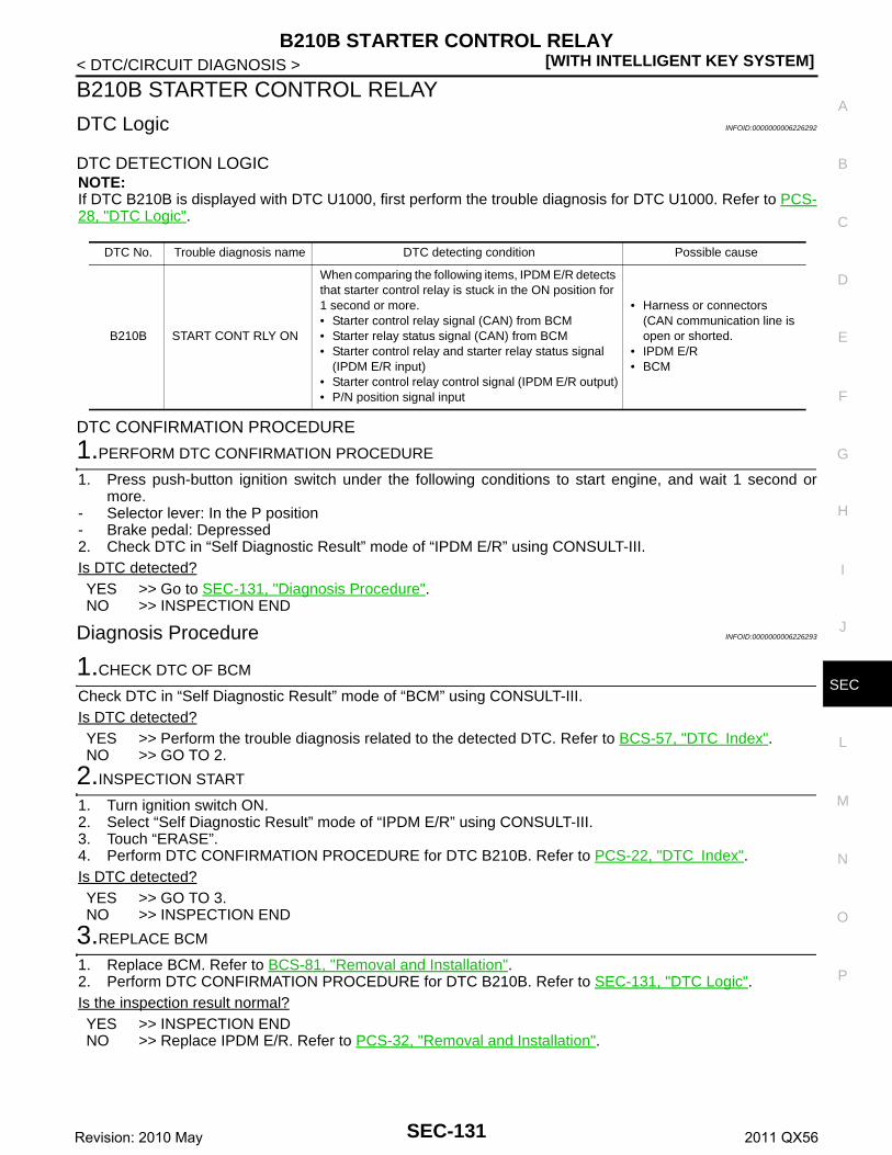
B210B STARTER CONTROL RELAY[WITH INTELLIGENT KEY SYSTEM]
C
D
E
F
G
H
I
J
L
M
A
B
EC
N
O
P
< DTC/CIRCUIT DIAGNOSIS >
S
B210B STARTER CONTROL RELAY
DTC Logic INFOID:0000000006226292
DTC DETECTION LOGICNOTE:If DTC B210B is displayed with DTC U1000, first perform the trouble diagnosis for DTC U1000. Refer to PCS-28, "DTC Logic".
DTC CONFIRMATION PROCEDURE
1.PERFORM DTC CONFIRMATION PROCEDURE
1. Press push-button ignition switch under the following conditions to start engine, and wait 1 second ormore.
- Selector lever: In the P position- Brake pedal: Depressed2. Check DTC in “Self Diagnostic Result” mode of “IPDM E/R” using CONSULT-III.Is DTC detected?YES >> Go to SEC-131, "Diagnosis Procedure".NO >> INSPECTION END
Diagnosis Procedure INFOID:0000000006226293
1.CHECK DTC OF BCM
Check DTC in “Self Diagnostic Result” mode of “BCM” using CONSULT-III.Is DTC detected?YES >> Perform the trouble diagnosis related to the detected DTC. Refer to BCS-57, "DTC Index".NO >> GO TO 2.
2.INSPECTION START
1. Turn ignition switch ON.2. Select “Self Diagnostic Result” mode of “IPDM E/R” using CONSULT-III.3. Touch “ERASE”.4. Perform DTC CONFIRMATION PROCEDURE for DTC B210B. Refer to PCS-22, "DTC Index".Is DTC detected?YES >> GO TO 3.NO >> INSPECTION END
3.REPLACE BCM
1. Replace BCM. Refer to BCS-81, "Removal and Installation".2. Perform DTC CONFIRMATION PROCEDURE for DTC B210B. Refer to SEC-131, "DTC Logic".Is the inspection result normal?YES >> INSPECTION ENDNO >> Replace IPDM E/R. Refer to PCS-32, "Removal and Installation".
DTC No. Trouble diagnosis name DTC detecting condition Possible cause
B210B START CONT RLY ON
When comparing the following items, IPDM E/R detects that starter control relay is stuck in the ON position for 1 second or more.• Starter control relay signal (CAN) from BCM• Starter relay status signal (CAN) from BCM• Starter control relay and starter relay status signal
(IPDM E/R input)• Starter control relay control signal (IPDM E/R output)• P/N position signal input
• Harness or connectors(CAN communication line is open or shorted.
• IPDM E/R• BCM
SEC-131Revision: 2010 May 2011 QX56

[WITH INTELLIGENT KEY SYSTEM]B210C STARTER CONTROL RELAY
< DTC/CIRCUIT DIAGNOSIS >
B210C STARTER CONTROL RELAY
DTC Logic INFOID:0000000006226294
DTC DETECTION LOGICNOTE:• If DTC B210C is displayed with DTC U1000, first perform the trouble diagnosis for DTC U1000. Refer to
PCS-28, "DTC Logic".• When IPDM E/R power supply voltage is low (Approx. 7 - 8 V for about 1 second), the DTC B210C may be
detected.
DTC CONFIRMATION PROCEDURE
1.PERFORM DTC CONFIRMATION PROCEDURE
1. Press push-button ignition switch under the following conditions to start engine, and wait 1 second ormore.
- Selector lever: In the P position- Brake pedal: Depressed2. Check DTC in “Self Diagnostic Result” mode of “IPDM E/R” using CONSULT-III.Is DTC detected?YES >> Go to SEC-132, "Diagnosis Procedure".NO >> INSPECTION END
Diagnosis Procedure INFOID:0000000006226295
1.CHECK DTC OF BCM
Check DTC in “Self Diagnostic Result” mode of “BCM” using CONSULT-III.Is DTC detected?YES >> Perform the trouble diagnosis related to the detected DTC. Refer to BCS-57, "DTC Index".NO >> GO TO 2.
2.INSPECTION START
1. Turn ignition switch ON.2. Select “Self Diagnostic Result” mode of “IPDM E/R” using CONSULT-III.3. Touch “ERASE”.4. Perform DTC CONFIRMATION PROCEDURE for DTC B210C. Refer to SEC-132, "DTC Logic".Is DTC detected?YES >> GO TO 3.NO >> INSPECTION END
3.REPLACE BCM
1. Replace BCM. Refer to BCS-81, "Removal and Installation".2. Perform DTC CONFIRMATION PROCEDURE for DTC B210C. Refer to SEC-132, "DTC Logic".Is the inspection result normal?YES >> INSPECTION ENDNO >> Replace IPDM E/R. Refer to PCS-32, "Removal and Installation".
DTC No. Trouble diagnosis name DTC detecting condition Possible cause
B210C START CONT RLY OFF
When comparing the following items, IPDM E/R detects that starter control relay is stuck in the OFF position for 1 second or more.• Starter control relay signal (CAN) from BCM• Starter relay status signal (CAN) from BCM• Starter control relay and starter relay status signal (IP-
DM E/R input)• Starter control relay control signal (IPDM E/R output)• P/N position signal input
• Harness or connectors(CAN communication line is open or shorted.
• IPDM E/R• BCM
SEC-132Revision: 2010 May 2011 QX56

B210D STARTER RELAY[WITH INTELLIGENT KEY SYSTEM]
C
D
E
F
G
H
I
J
L
M
A
B
EC
N
O
P
< DTC/CIRCUIT DIAGNOSIS >
S
B210D STARTER RELAY
DTC Logic INFOID:0000000006226296
DTC DETECTION LOGICNOTE:If DTC B210D is displayed with DTC U1000, first perform the trouble diagnosis for DTC U1000. Refer to PCS-28, "DTC Logic".
DTC CONFIRMATION PROCEDURE
1.PERFORM DTC CONFIRMATION PROCEDURE
1. Press push-button ignition switch under the following conditions to start engine, and wait 1 second ormore.
- Selector lever: In the P position- Brake pedal: Depressed2. Check DTC in “Self Diagnostic Result” mode of “IPDM E/R” using CONSULT-III.Is DTC detected?YES >> Go to SEC-133, "Diagnosis Procedure".NO >> INSPECTION END
Diagnosis Procedure INFOID:0000000006226297
1.INSPECTION START
1. Turn ignition switch ON.2. Select “Self Diagnostic Result” mode of “IPDM E/R” using CONSULT-III.3. Touch “ERASE”.4. Perform DTC CONFIRMATION PROCEDURE for DTC B210D. Refer to SEC-133, "DTC Logic".Is DTC detected?YES >> Replace IPDM E/R. Refer to PCS-32, "Removal and Installation".NO >> INSPECTION END
DTC No. Trouble diagnosis name DTC detecting condition Possible cause
B210D STARTER RELAY ON
When comparing the following items, IPDM E/R detects that starter relay is stuck in the ON position for 1 second or more.• Starter control relay signal (CAN) from BCM• Starter relay status signal (CAN) from BCM• Starter control relay and starter relay status signal
(IPDM E/R input)• Starter control relay control signal (IPDM E/R output)• P/N position signal input
• Harness or connectors(CAN communication line is open or shorted.
• IPDM E/R
SEC-133Revision: 2010 May 2011 QX56

[WITH INTELLIGENT KEY SYSTEM]B210E STARTER RELAY
< DTC/CIRCUIT DIAGNOSIS >
B210E STARTER RELAY
DTC Logic INFOID:0000000006226298
DTC DETECTION LOGICNOTE:• If DTC B210E is displayed with DTC U1000, first perform the trouble diagnosis for DTC U1000. Refer to
PCS-28, "DTC Logic".• If DTC B210E is displayed with DTC B2605, first perform the trouble diagnosis for DTC B2605. Refer to
SEC-91, "DTC Logic".• When IPDM E/R power supply voltage is low (Approx. 7 - 8 V for about 1 second), the DTC B210E may be
detected.
DTC CONFIRMATION PROCEDURE
1.PERFORM DTC CONFIRMATION PROCEDURE
1. Press push-button ignition switch under the following conditions to start engine, and wait 1 second ormore.
- Selector lever: In the P position- Brake pedal: Depressed2. Check DTC in “Self Diagnostic Result” mode of “IPDM E/R” using CONSULT-III.Is DTC detected?YES >> Go to SEC-134, "Diagnosis Procedure".NO >> INSPECTION END
Diagnosis Procedure INFOID:0000000006226299
1.CHECK STARTER RELAY OUTPUT SIGNAL
1. Check voltage between BCM harness connector and ground.
Is the inspection result normal?YES >> GO TO 3.NO >> GO TO 2.
2.CHECK STARTER RELAY OUTPUT SIGNAL CIRCUIT
1. Turn ignition switch OFF.2. Disconnect BCM connector.3. Disconnect IPDM E/R connector.4. Check continuity between BCM harness connector and IPDM E/R harness connector.
DTC No. Trouble diagnosis name DTC detecting condition Possible cause
B210E STARTER RELAY OFF
When comparing the following items, IPDM E/R detects that starter relay is stuck in the OFF posi-tion for 1 second or more.• Starter control relay signal (CAN) from BCM• Starter relay status signal (CAN) from BCM• Starter control relay and starter relay status
signal (IPDM E/R input)• Starter control relay control signal (IPDM E/R
output)• P/N position signal input
• Harness or connector(CAN communication line is open or shorted.)
• Harness or connector(Starter relay circuit is open or shorted.)
• IPDM E/R• BCM• Battery
(+)
(–)Condition Voltage (V)
(Approx.)BCM
Connector Terminal Ignition switch Brake pedal Selector lever
M71 97 Ground ON Depressed
P or N 12
Other than above
0
SEC-134Revision: 2010 May 2011 QX56

B210E STARTER RELAY[WITH INTELLIGENT KEY SYSTEM]
C
D
E
F
G
H
I
J
L
M
A
B
EC
N
O
P
< DTC/CIRCUIT DIAGNOSIS >
S
5. Check continuity between BCM harness connector and ground.
Is the inspection result normal?YES >> Replace IPDM E/R. Refer to PCS-32, "Removal and Installation".NO >> Repair or replace harness.
3.CHECK STARTER RELAY CIRCUIT
1. Turn ignition switch OFF.2. Disconnect IPDM E/R connector.3. Check voltage between IPDM E/R harness connector and ground.
Is the inspection result normal?YES >> GO TO 4.NO >> Check harness for open or short between IPDM E/R and battery. Refer to STR-7, "Wiring Dia-
gram".
4.REPLACE BCM
1. Replace BCM. Refer to BCS-81, "Removal and Installation".2. Perform DTC CONFIRMATION PROCEDIURE for DTC B210E. Refer to SEC-134, "DTC Logic".Is the inspection result normal?YES >> INSPECTION ENDNO >> Replace IPDM E/R. Refer to PCS-32, "Removal and Installation".
BCM IPDM E/RContinuity
Connector Terminal Connector Terminal
M71 97 E13 30 Existed
BCM
GroundContinuity
Connector Terminal
M71 97 Not existed
(+)
(–)Voltage (V)(Approx.)
IPDM E/R
Connector Terminal
E10 4 Ground Battery voltage
SEC-135Revision: 2010 May 2011 QX56

[WITH INTELLIGENT KEY SYSTEM]B210F SHIFT POSITION/CLUTCH INTERLOCK SWITCH
< DTC/CIRCUIT DIAGNOSIS >
B210F SHIFT POSITION/CLUTCH INTERLOCK SWITCH
DTC Logic INFOID:0000000006226300
DTC DETECTION LOGICNOTE:If DTC B210F is displayed with DTC U1000, first perform the trouble diagnosis for DTC U1000. Refer to PCS-28, "DTC Logic".
DTC CONFIRMATION PROCEDURE
1.PERFORM DTC CONFIRMATION PROCEDURE
1. Shift selector lever to the P position. 2. Turn ignition switch ON and wait 1 second or more.3. Shift selector lever to the N position and wait 1 second or more. 4. Shift selector lever to any position other than P and N, and wait 1 second or more. 5. Check DTC in “Self Diagnostic Result” mode of “IPDM E/R” using CONSULT-III.Is DTC detected?YES >> Go to SEC-136, "Diagnosis Procedure".NO >> INSPECTION END
Diagnosis Procedure INFOID:0000000006226301
1.CHECK DTC OF BCM
Check DTC in “Self Diagnostic Result” mode of “BCM” using CONSULT-III.Is DTC detected?YES >> Perform the trouble diagnosis related to the detected DTC. Refer to BCS-57, "DTC Index".NO >> GO TO 2.
2.CHECK DTC OF TCM
Check DTC in “Self Diagnostic Result” mode of “TCM” using CONSULT-III.Is DTC detected?YES >> Perform the trouble diagnosis related to the detected DTC. Refer to TM-78, "DTC Index".NO >> GO TO 3.
3.CHECK IPDM E/R SIGNAL CIRCUIT OPEN AND SHORT
1. Turn ignition switch OFF.2. Disconnect IPDM E/R connector.3. Disconnect A/T assembly connector.4. Check continuity between IPDM E/R harness connector and A/T assembly harness connector.
5. Check continuity between IPDM E/R harness connector and ground.
DTC No. Trouble diagnosis name DTC detecting condition Possible cause
B210F INTER LOCK/PNP SW ONThere is a difference between P/N position signal from TCM and P/N position signal from BCM (CAN).
• Harness or connectors(CAN communication line is open or shorted.)
• Harness or connectors(TCM circuit is open or shorted.)
• A/T assembly (TCM)• IPDM E/R• BCM
IPDM E/R A/T assemblyContinuity
Connector Terminal Connector Terminal
E15 48 F51 9 Existed
SEC-136Revision: 2010 May 2011 QX56

B210F SHIFT POSITION/CLUTCH INTERLOCK SWITCH[WITH INTELLIGENT KEY SYSTEM]
C
D
E
F
G
H
I
J
L
M
A
B
EC
N
O
P
< DTC/CIRCUIT DIAGNOSIS >
S
Is the inspection result normal?YES >> Replace IPDM E/R. Refer to PCS-32, "Removal and Installation".NO >> Repair or replace harness.
(+)
(–) ContinuityIPDM E/R
Connector Terminal
E15 48 Ground Not existed
SEC-137Revision: 2010 May 2011 QX56

[WITH INTELLIGENT KEY SYSTEM]B2110 SHIFT POSITION/CLUTCH INTERLOCK SWITCH
< DTC/CIRCUIT DIAGNOSIS >
B2110 SHIFT POSITION/CLUTCH INTERLOCK SWITCH
DTC Logic INFOID:0000000006226302
DTC DETECTION LOGICNOTE:If DTC B2110 is displayed with DTC U1000, first perform the trouble diagnosis for DTC U1000. Refer to PCS-28, "DTC Logic".
DTC CONFIRMATION PROCEDURE
1.PERFORM DTC CONFIRMATION PROCEDURE
1. Shift selector lever to the P position.2. Turn ignition switch ON and wait 1 second or more.3. Shift selector lever to the N position and wait 1 second or more.4. Shift selector lever to any position other than P and N, and wait 1 second or more.5. Check DTC in “Self Diagnostic Result” mode of “IPDM E/R” using CONSULT-III.Is DTC detected?YES >> Go to SEC-138, "Diagnosis Procedure".NO >> INSPECTION END
Diagnosis Procedure INFOID:0000000006226303
1.CHECK DTC OF BCM
Check DTC in “Self Diagnostic Result” mode of “BCM” using CONSULT-III.Is DTC detected?YES >> Perform the trouble diagnosis related to the detected DTC. Refer to BCS-57, "DTC Index".NO >> GO TO 2.
2.CHECK DTC OF TCM
Check DTC in “Self Diagnostic Result” mode of “TCM” using CONSULT-III.Is DTC detected?YES >> Perform the trouble diagnosis related to the detected DTC. Refer to TM-78, "DTC Index".NO >> GO TO 3.
3.CHECK IPDM E/R SIGNAL CIRCUIT OPEN AND SHORT
1. Turn ignition switch OFF.2. Disconnect IPDM E/R connector.3. Disconnect A/T assembly connector.4. Check continuity between IPDM E/R harness connector and A/T assembly harness connector.
5. Check continuity between IPDM E/R harness connector and ground.
DTC No. Trouble diagnosis name DTC detecting condition Possible cause
B2110 INTER LOCK/PNP SW OFFThere is a difference between P/N position signal from TCM and P/N position signal from BCM (CAN).
• Harness or connectors(CAN communication line is open or shorted.)
• Harness or connectors(TCM circuit is open or shorted.)
• A/T assembly (TCM)• IPDM E/R• BCM
IPDM E/R A/T assemblyContinuity
Connector Terminal Connector Terminal
E15 48 F51 9 Existed
SEC-138Revision: 2010 May 2011 QX56

B2110 SHIFT POSITION/CLUTCH INTERLOCK SWITCH[WITH INTELLIGENT KEY SYSTEM]
C
D
E
F
G
H
I
J
L
M
A
B
EC
N
O
P
< DTC/CIRCUIT DIAGNOSIS >
S
Is the inspection result normal?YES >> Replace IPDM E/R. Refer to PCS-32, "Removal and Installation".NO >> Repair or replace harness.
(+)
(–) ContinuityIPDM E/R
Connector Terminal
E15 48 Ground Not existed
SEC-139Revision: 2010 May 2011 QX56

[WITH INTELLIGENT KEY SYSTEM]HEADLAMP FUNCTION
< DTC/CIRCUIT DIAGNOSIS >
HEADLAMP FUNCTION
Component Function Check INFOID:0000000006226719
1.CHECK FUNCTION
1. Perform “HEAD LAMP(HI)” in “ACTIVE TEST” mode of “THEFT ALM” of “BCM” using CONSULT-III.2. Check headlamps operation.
Is the inspection result normal?YES >> INSPECTION ENDNO >> Refer to SEC-140, "Diagnosis Procedure".
Diagnosis Procedure INFOID:0000000006226720
1.CHECK HEADLAMP FUNCTION
Refer to EXL-86, "Component Function Check".Is the inspection result normal?YES >> GO TO 2.NO >> Repair or replace the malfunctioning parts.
2.CHECK INTERMITTENT INCIDENT
Refer to GI-40, "Intermittent Incident".
>> INSPECTION END
Test item Description
HEAD LAMP (HI)ON
Headlamps (Hi)Light
OFF Do not light
SEC-140Revision: 2010 May 2011 QX56
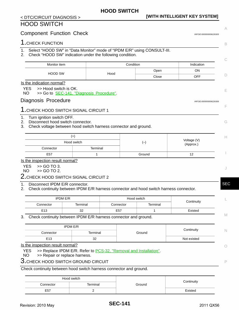
HOOD SWITCH[WITH INTELLIGENT KEY SYSTEM]
C
D
E
F
G
H
I
J
L
M
A
B
EC
N
O
P
< DTC/CIRCUIT DIAGNOSIS >
S
HOOD SWITCH
Component Function Check INFOID:0000000006226305
1.CHECK FUNCTION
1. Select “HOOD SW” in “Data Monitor” mode of “IPDM E/R” using CONSULT-III. 2. Check “HOOD SW” indication under the following condition.
Is the indication normal?YES >> Hood switch is OK.NO >> Go to SEC-141, "Diagnosis Procedure".
Diagnosis Procedure INFOID:0000000006226306
1.CHECK HOOD SWITCH SIGNAL CIRCUIT 1
1. Turn ignition switch OFF.2. Disconnect hood switch connector.3. Check voltage between hood switch harness connector and ground.
Is the inspection result normal?YES >> GO TO 3.NO >> GO TO 2.
2.CHECK HOOD SWITCH SIGNAL CIRCUIT 2
1. Disconnect IPDM E/R connector.2. Check continuity between IPDM E/R harness connector and hood switch harness connector.
3. Check continuity between IPDM E/R harness connector and ground.
Is the inspection result normal?YES >> Replace IPDM E/R. Refer to PCS-32, "Removal and Installation".NO >> Repair or replace harness.
3.CHECK HOOD SWITCH GROUND CIRCUIT
Check continuity between hood switch harness connector and ground.
Monitor item Condition Indication
HOOD SW HoodOpen ON
Close OFF
(+)
(–)Voltage (V)(Approx.)
Hood switch
Connector Terminal
E57 1 Ground 12
IPDM E/R Hood switchContinuity
Connector Terminal Connector Terminal
E13 32 E57 1 Existed
IPDM E/R
GroundContinuity
Connector Terminal
E13 32 Not existed
Hood switch
GroundContinuity
Connector Terminal
E57 2 Existed
SEC-141Revision: 2010 May 2011 QX56

[WITH INTELLIGENT KEY SYSTEM]HOOD SWITCH
< DTC/CIRCUIT DIAGNOSIS >Is the inspection result normal?YES >> GO TO 4.NO >> Repair or replace harness.
4.CHECK HOOD SWITCH
Refer to SEC-142, "Component Inspection".Is the inspection result normal?YES >> GO TO 5.NO >> Replace hood switch.
5.CHECK INTERMITTENT INCIDENT
Refer to GI-40, "Intermittent Incident".
>> INSPECTION END
Component Inspection INFOID:0000000006226307
1.CHECK HOOD SWITCH
1. Turn ignition switch OFF.2. Disconnect hood switch connector.3. Check continuity between hood switch terminals.
Is the inspection result normal?YES >> INSPECTION ENDNO >> Replace hood switch.
Hood switchCondition Continuity
Terminal
1 2 Hood switchPress Not existed
Release Existed
SEC-142Revision: 2010 May 2011 QX56

HORN FUNCTION[WITH INTELLIGENT KEY SYSTEM]
C
D
E
F
G
H
I
J
L
M
A
B
EC
N
O
P
< DTC/CIRCUIT DIAGNOSIS >
S
HORN FUNCTION
Component Function Check INFOID:0000000006226308
1.CHECK FUNCTION 1
1. Disconnect vehicle security horn relay.2. Perform “VEHICLE SECURITY HORN” in “ACTIVE TEST” mode of “THEFT ALM” of “BCM” using CON-
SULT-III.3. Check the horn operation.
Is the operation normal?YES >> GO TO 2.NO >> Go to SEC-143, "Diagnosis Procedure".
2.CHECK FUNCTION 2
1. Reconnect vehicle security horn relay.2. Disconnect horn relay.3. Perform “VEHICLE SECURITY HORN” in “ACTIVE TEST” mode of “THEFT ALM” of “BCM” using CON-
SULT-III.4. Check the horn operation.
Is the operation normal?YES >> INSPECTION ENDNO >> Go to SEC-143, "Diagnosis Procedure".
Diagnosis Procedure INFOID:0000000006226309
1.INSPECTION START
Perform inspection in accordance with procedure that confirms malfunction.Which procedure confirms malfunction?Component Function Check 1>>GO TO 2.Component Function Check 2>>GO TO 4.
2.CHECK HORN FUNCTION
Check that horns function properly using horn switch.Do horns sound?YES >> GO TO 3.NO >> Check horn circuit. Refer to HRN-3, "Wiring Diagram".
3.CHECK HORN CONTROL CIRCUIT
1. Disconnect horn relay.2. Disconnect IPDM E/R connector.3. Check continuity between IPDM E/R harness connector and horn relay harness connector.
4. Check continuity between IPDM E/R harness connector and ground.
Test item Description
VEHICLE SECURITY HORN ON Horn Sounds (for 0.5 sec)
Test item Description
VEHICLE SECURITY HORN ON Vehicle security horn Sounds (for 0.5 sec)
IPDM E/R Horn relayContinuity
Connector Terminal Connector Terminal
E13 34 E5 1 Existed
SEC-143Revision: 2010 May 2011 QX56

[WITH INTELLIGENT KEY SYSTEM]HORN FUNCTION
< DTC/CIRCUIT DIAGNOSIS >
Is the inspection result normal?YES >> Replace IPDM E/R. Refer to PCS-32, "Removal and Installation".NO >> Repair or replace harness.
4.CHECK VEHICLE SECURITY HORN RELAY POWER SUPPLY
1. Disconnect vehicle security horn relay.2. Check voltage between vehicle security horn relay harness connector and ground.
Is the inspection result normal?YES >> GO TO 5.NO-1 >> Check 10 A fuse [No. 36 located in the fuse block (J/B)].NO-2 >> Check harness for open or short between vehicle security horn relay and fuse.
5.CHECK VEHICLE SECURITY HORN CONTROL CIRCUIT
1. Disconnect IPDM E/R connector.2. Check continuity between IPDM E/R harness connector and vehicle security horn relay harness connec-
tor.
3. Check continuity between IPDM E/R harness connector and ground.
Is the inspection result normal?YES >> GO TO 6.NO >> Repair or replace harness.
6.CHECK VEHICLE SECURITY HORN CIRCUIT
1. Disconnect vehicle security horn connector.2. Check continuity between vehicle security horn relay harness connector and vehicle security horn har-
ness connector.
3. Check continuity between vehicle security horn relay harness connector and ground.
Is the inspection result normal?YES >> GO TO 7.
IPDM E/R
GroundContinuity
Connector Terminal
E13 34 Not existed
(+)
(–)Voltage (V)(Approx.)
Vehicle security horn relay
Connector Terminal
E124 1 Ground Battery voltage
IPDM E/R Vehicle security horn relayContinuity
Connector Terminal Connector Terminal
E13 34 E124 3 Existed
IPDM E/R
GroundContinuity
Connector Terminal
E13 34 Not existed
Vehicle security horn relay Vehicle security hornContinuity
Connector Terminal Connector Terminal
E124 2 E125 1 Existed
Vehicle security horn relay
GroundContinuity
Connector Terminal
E124 2 Not existed
SEC-144Revision: 2010 May 2011 QX56

HORN FUNCTION[WITH INTELLIGENT KEY SYSTEM]
C
D
E
F
G
H
I
J
L
M
A
B
EC
N
O
P
< DTC/CIRCUIT DIAGNOSIS >
S
NO >> Repair or replace harness.
7.CHECK VEHICLE SECURITY HORN RELAY
Refer to SEC-145, "Component Inspection".Is the inspection result normal?YES >> Replace vehicle security horn.NO >> Replace vehicle security horn relay.
Component Inspection INFOID:0000000006248777
1.CHECK VEHICLE SECURITY HORN RELAY
1. Turn ignition switch OFF.2. Disconnect vehicle security horn relay.3. Check voltage between vehicle security horn relay terminal and ground under the following conditions.
Is the inspection result normal?YES >> INSPECTION ENDNO >> Replace vehicle security horn relay.
(+)
(−) ConditionVoltage (V)(Approx.)
Vehicle security horn relay
Terminal
2 Ground12 V direct current supply between terminals 1 and 3 12
No current supply 0
SEC-145Revision: 2010 May 2011 QX56

[WITH INTELLIGENT KEY SYSTEM]SECURITY INDICATOR LAMP
< DTC/CIRCUIT DIAGNOSIS >
SECURITY INDICATOR LAMP
Component Function Check INFOID:0000000006226312
1.CHECK FUNCTION
1. Perform “THEFT IND” in “ACTIVE TEST” mode of “IMMU” of “BCM” using CONSULT-III.2. Check security indicator lamp operation.
Is the inspection result normal?YES >> INSPECTION ENDNO >> Go to SEC-146, "Diagnosis Procedure".
Diagnosis Procedure INFOID:0000000006226313
1.CHECK SECURITY INDICATOR LAMP POWER SUPPLY CIRCUIT
1. Turn ignition switch OFF.2. Disconnect combination meter connector.3. Check voltage between combination meter harness connector and ground.
Is the inspection result normal?YES >> GO TO 2.NO-1 >> Check 10 A fuse [No. 11, located in the fuse block (J/B)].NO-2 >> Check harness for open or short between combination meter and fuse.
2.CHECK SECURITY INDICATOR LAMP SIGNAL
1. Connect combination meter connector.2. Disconnect BCM connector.3. Check voltage between BCM harness connector and ground.
Is the inspection result normal?YES >> GO TO 3.NO >> GO TO 4.
3.REPLACE BCM
1. Replace BCM. Refer to BCS-81, "Removal and Installation".2. Perform initialization of BCM and registration of all Intelligent Keys using CONSULT-III.
For initialization and registration procedures, refer to CONSULT-III Operation Manual NATS-IVIS/NVIS.
>> INSPECTION END
4.CHECK SECURITY INDICATOR LAMP CIRCUIT
1. Disconnect combination meter connector.2. Check continuity between combination meter harness connector and BCM harness connector.
Test item Description
THEFT INDON
Security indicator lampIlluminates
OFF Does not illuminate
(+)
(–)Voltage (V)(Approx.)
Combination meter
Connector Terminal
M34 1 Ground Battery voltage
(+)
(–)Voltage (V)(Approx.)
BCM
Connector Terminal
M68 23 Ground Battery voltage
SEC-146Revision: 2010 May 2011 QX56

SECURITY INDICATOR LAMP[WITH INTELLIGENT KEY SYSTEM]
C
D
E
F
G
H
I
J
L
M
A
B
EC
N
O
P
< DTC/CIRCUIT DIAGNOSIS >
S
3. Check continuity between combination meter harness connector and ground.
Is the inspection result normal?YES >> Replace combination meter. Refer to MWI-85, "Removal and Installation".NO >> Repair or replace harness.
Combination meter BCMContinuity
Connector Terminal Connector Terminal
M34 28 M68 23 Existed
Combination meter
GroundContinuity
Connector Terminal
M34 28 Not existed
SEC-147Revision: 2010 May 2011 QX56

[WITH INTELLIGENT KEY SYSTEM]ENGINE DOES NOT START WHEN INTELLIGENT KEY IS INSIDE OF VEHICLE
< SYMPTOM DIAGNOSIS >
SYMPTOM DIAGNOSISENGINE DOES NOT START WHEN INTELLIGENT KEY IS INSIDE OF VE-HICLE
Description INFOID:0000000006226323
Engine does not start when push-button ignition switch is pressed while carrying Intelligent Key.NOTE:• Check that vehicle is under the condition shown in “Conditions of vehicle” before starting diagnosis, and
check each symptom.• The engine start function, door lock function, power distribution system, and NATS-IVIS/NVIS in the Intelli-
gent Key system are closely related to each other regarding control. The vehicle security function can oper-ate only when the door lock and power distribution system are operating normally.
Conditions of Vehicle (Operating Conditions)• “ENGINE START BY I-KEY” in “WORK SUPPORT” is ON when setting on CONSULT-III.• Intelligent Key is not inserted in key slot.• One or more of Intelligent Keys with registered Intelligent Key ID is in the vehicle.
Diagnosis Procedure INFOID:0000000006226324
1.PERFORM WORK SUPPORT
Perform “INSIDE ANT DIAGNOSIS” on Work Support in “INTELLIGENT KEY”.Refer to SEC-22, "INTELLIGENT KEY : CONSULT-III Function (BCM - INTELLIGENT KEY)".
>> GO TO 2.
2.PERFORM SELF-DIAGNOSIS RESULT
Perform Self-Diagnosis Result in “BCM”, and check whether or not DTC of inside key antenna is detected.Is DTC detected?YES >> Refer to BCS-57, "DTC Index".NO >> GO TO 3.
3.CHECK PUSH-BUTTON IGNITION SWITCH
Check push-button ignition switch.Refer to PCS-71, "Component Function Check".Is the operation normal?YES >> GO TO 4.NO >> Repair or replace malfunctioning parts.
4.CONFIRM THE OPERATION
Confirm the operation again.Is the inspection normal?YES >> Check intermittent incident. Refer to GI-40, "Intermittent Incident".NO >> GO TO 1.
SEC-148Revision: 2010 May 2011 QX56

STEERING DOES NOT LOCK[WITH INTELLIGENT KEY SYSTEM]
C
D
E
F
G
H
I
J
L
M
A
B
EC
N
O
P
< SYMPTOM DIAGNOSIS >
S
STEERING DOES NOT LOCK
Description INFOID:0000000006226325
Steering does not lock when door is open while ignition switch is OFF.NOTE:Before performing the diagnosis, check “Work Flow”. Refer to SEC-48, "Work Flow".
Diagnosis Procedure INFOID:0000000006226326
1.CHECK DOOR SWITCH
Check door switch.Refer to DLK-117, "Component Function Check".Is the inspection normal?YES >> GO TO 2.NO >> Repair or replace malfunctioning parts.
2.CONFIRM THE OPERATION
Confirm the operation again.Is the inspection normal?YES >> Check intermittent incident. Refer to GI-40, "Intermittent Incident".NO >> GO TO 1.
SEC-149Revision: 2010 May 2011 QX56

[WITH INTELLIGENT KEY SYSTEM]SECURITY INDICATOR LAMP DOES NOT TURN ON OR BLINK
< SYMPTOM DIAGNOSIS >
SECURITY INDICATOR LAMP DOES NOT TURN ON OR BLINK
Description INFOID:0000000006226327
Security indicator lamp does not blink when ignition switch is in a position other than ONNOTE:• Before performing the diagnosis, check “Work Flow”. Refer to SEC-48, "Work Flow".• Check that vehicle is under the condition shown in “Conditions of vehicle” before starting diagnosis, and
check each symptom.
Conditions of Vehicle (Operating Conditions)Ignition switch is not in the ON position.
Diagnosis Procedure INFOID:0000000006226328
1.CHECK SECURITY INDICATOR LAMP
Check security indicator lamp.Refer to SEC-146, "Component Function Check".Is the inspection result normal?YES >> GO TO 2.NO >> Repair or replace the malfunctioning parts.
2.CONFIRM THE OPERATION
Confirm the operation again.Is the result normal?YES >> Check intermittent incident. Refer to GI-40, "Intermittent Incident".NO >> GO TO 1.
SEC-150Revision: 2010 May 2011 QX56
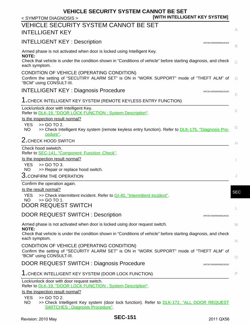
VEHICLE SECURITY SYSTEM CANNOT BE SET[WITH INTELLIGENT KEY SYSTEM]
C
D
E
F
G
H
I
J
L
M
A
B
EC
N
O
P
< SYMPTOM DIAGNOSIS >
S
VEHICLE SECURITY SYSTEM CANNOT BE SETINTELLIGENT KEY
INTELLIGENT KEY : Description INFOID:0000000006226329
Armed phase is not activated when door is locked using Intelligent Key.NOTE:Check that vehicle is under the condition shown in “Conditions of vehicle” before starting diagnosis, and checkeach symptom.
CONDITION OF VEHICLE (OPERATING CONDITION)Confirm the setting of “SECUTIRY ALARM SET” is ON in “WORK SUPPORT” mode of “THEFT ALM” of“BCM” using CONSULT-III.
INTELLIGENT KEY : Diagnosis Procedure INFOID:0000000006226330
1.CHECK INTELLIGENT KEY SYSTEM (REMOTE KEYLESS ENTRY FUNCTION)
Lock/unlock door with Intelligent Key.Refer to DLK-19, "DOOR LOCK FUNCTION : System Description".Is the inspection result normal?YES >> GO TO 2.NO >> Check Intelligent Key system (remote keyless entry function). Refer to DLK-175, "Diagnosis Pro-
cedure".
2.CHECK HOOD SWITCH
Check hood swiwtch.Refer to SEC-141, "Component Function Check".Is the inspection result normal?YES >> GO TO 3.NO >> Repair or replace hood switch.
3.CONFIRM THE OPERATION
Confirm the operation again.Is the result normal?YES >> Check intermittent incident. Refer to GI-40, "Intermittent Incident".NO >> GO TO 1.
DOOR REQUEST SWITCH
DOOR REQUEST SWITCH : Description INFOID:0000000006226331
Armed phase is not activated when door is locked using door request switch.NOTE:Check that vehicle is under the condition shown in “Conditions of vehicle” before starting diagnosis, and checkeach symptom.
CONDITION OF VEHICLE (OPERATING CONDITION)Confirm the setting of “SECURITY ALARM SET” is ON in “WORK SUPPORT” mode of “THEFT ALM” of“BCM” using CONSULT-III.
DOOR REQUEST SWITCH : Diagnosis Procedure INFOID:0000000006226332
1.CHECK INTELLIGENT KEY SYSTEM (DOOR LOCK FUNCTION)
Lock/unlock door with door request switch.Refer to DLK-19, "DOOR LOCK FUNCTION : System Description".Is the inspection result normal?YES >> GO TO 2.NO >> Check Intelligent Key system (door lock function). Refer to DLK-172, "ALL DOOR REQUEST
SWITCHES : Diagnosis Procedure".
SEC-151Revision: 2010 May 2011 QX56

[WITH INTELLIGENT KEY SYSTEM]VEHICLE SECURITY SYSTEM CANNOT BE SET
< SYMPTOM DIAGNOSIS >
2.CHECK HOOD SWITCH
Check hood swiwtch.Refer to SEC-141, "Component Function Check".Is the inspection result normal?YES >> GO TO 3.NO >> Repair or replace hood switch.
3.CONFIRM THE OPERATION
Confirm the operation again.Is the result normal?YES >> Check intermittent incident. Refer to GI-40, "Intermittent Incident".NO >> GO TO 1.
DOOR KEY CYLINDER
DOOR KEY CYLINDER : Description INFOID:0000000006375072
Armed phase is not activated when door is locked using mechanical key.NOTE:Check that vehicle is under the condition shown in “Conditions of vehicle” before starting diagnosis, and checkeach symptom.
CONDITION OF VEHICLE (OPERATING CONDITION)Confirm the setting of “SECURITY ALARM SET” is ON in “WORK SUPPORT” mode of “THEFT ALM” of“BCM” using CONSULT-III.
DOOR KEY CYLINDER : Diagnosis Procedure INFOID:0000000006375073
1.CHECK POWER DOOR LOCK SYSTEM
Lock/unlock door with mechanical key.Refer to DLK-16, "System Description".Is the inspection result normal?YES >> GO TO 2.NO >> Check power door lock system. Refer to DLK-171, "Diagnosis Procedure".
2.CONFIRM THE OPERATION
Confirm the operation again.Is the result normal?YES >> Check intermittent incident. Refer to GI-40, "Intermittent Incident".NO >> GO TO 1.
SEC-152Revision: 2010 May 2011 QX56

VEHICLE SECURITY ALARM DOES NOT ACTIVATE[WITH INTELLIGENT KEY SYSTEM]
C
D
E
F
G
H
I
J
L
M
A
B
EC
N
O
P
< SYMPTOM DIAGNOSIS >
S
VEHICLE SECURITY ALARM DOES NOT ACTIVATE
Description INFOID:0000000006226333
Alarm does not operate when alarm operating condition is satisfied.NOTE:Check that vehicle is under the condition shown in “Conditions of vehicle” before starting diagnosis, and checkeach symptom.
CONDITIONS OF VEHICLE (OPERATING CONDITIONS)Confirm the setting of “SECURITY ALARM SET” is ON in “WORK SUPPORT” mode of “THEFT ALM” of“BCM” using CONSULT-III.
Diagnosis Procedure INFOID:0000000006226334
1.CHECK DOOR SWITCH
Check door switch.Refer to DLK-117, "Component Function Check".Is the inspection result normal?YES >> GO TO 2.NO >> Replace the malfunctioning door switch
2.CHECK HOOD SWITCH
Check hood swiwtch.Refer to SEC-141, "Component Function Check".Is the inspection result normal?YES >> GO TO 3.NO >> Repair or replace hood switch.
3.CHECK HORN FUNCTION
Check horn function.Refer to SEC-143, "Component Function Check".Is the inspection result normal?YES >> GO TO 4.NO >> Repair or replace the malfunctioning parts.
4.CHECK HEADLAMP FUNCTION
Check headlamp function.Refer to SEC-140, "Component Function Check".Is the inspection result normal?YES >> GO TO 5.NO >> Repair or replace the malfunctioning parts.
5.CONFIRM THE OPERATION
Confirm the operation again.Is the result normal?YES >> Check intermittent incident. Refer to GI-40, "Intermittent Incident".NO >> GO TO 1.
SEC-153Revision: 2010 May 2011 QX56

[WITH INTELLIGENT KEY SYSTEM]PANIC ALARM FUNCTION DOES NOT OPERATE
< SYMPTOM DIAGNOSIS >
PANIC ALARM FUNCTION DOES NOT OPERATE
Description INFOID:0000000006226336
NOTE:• Before performing the diagnosis following procedure, check “Work Flow”. Refer to SEC-48, "Work Flow".• Check that vehicle is under the condition shown in “Conditions of vehicle” before starting diagnosis, and
check each symptom.
CONDITIONS OF VEHICLE (OPERATION CONDITIONS)• Ignition switch is in OFF or LOCK position.• Intelligent Key is removed from key slot.
Diagnosis Procedure INFOID:0000000006226337
1.CHECK REMOTE KEYLESS ENTRY FUNCTION
Check remote keyless entry function.Does door lock/unlock with Intelligent key button?YES >> GO TO 2.NO >> Go to DLK-175, "Diagnosis Procedure".
2.CHECK VEHICLE SECURITY ALARM OPERATION
Check vehicle security alarm operation.Does alarm (headlamps and horns) active?YES >> GO TO 3.NO >> Go to SEC-18, "VEHICLE SECURITY SYSTEM : System Description".
3.CHECK “PANIC ALARM SET” SETTING IN “WORK SUPPORT”
Check “PANIC ALARM SET” setting in “WORK SUPPORT”.Refer to SEC-22, "INTELLIGENT KEY : CONSULT-III Function (BCM - INTELLIGENT KEY)".Is the inspection result normal?YES >> GO TO 4.NO >> Set “PANIC ALARM SET” setting in “WORK SUPPORT”.
4.CONFIRM THE OPERATION
Confirm the operation again.Is the result normal?YES >> Check intermittent incident. Refer to GI-40, "Intermittent Incident".NO >> GO TO 1.
SEC-154Revision: 2010 May 2011 QX56

NATS ANTENNA AMP.[WITH INTELLIGENT KEY SYSTEM]
C
D
E
F
G
H
I
J
L
M
A
B
EC
N
O
P
< REMOVAL AND INSTALLATION >
S
REMOVAL AND INSTALLATIONNATS ANTENNA AMP.
Removal and Installation INFOID:0000000006226338
REMOVAL1. Remove the push-button ignition switch. Refer to SEC-156, "Removal and Installation".2. Disengage the NATS antenna amp. pawl, and then remove
NATS antenna amp.
INSTALLATIONInstall in the reverse order of removal.
: Pawl
JMKIA5307ZZ
SEC-155Revision: 2010 May 2011 QX56

[WITH INTELLIGENT KEY SYSTEM]PUSH-BUTTON IGNITION SWITCH
< REMOVAL AND INSTALLATION >
PUSH-BUTTON IGNITION SWITCH
Exploded View INFOID:0000000006226339
Refer to IP-13, "Exploded View".
Removal and Installation INFOID:0000000006226340
REMOVAL1. Remove the cluster lid A. Refer to IP-14, "Removal and Installation".2. Disengage the push-button ignition switch fixing pawl and then
remove push-button ignition switch.
INSTALLATIONInstall in the reverse order of removal.
: Pawl
JMKIA5306ZZ
SEC-156Revision: 2010 May 2011 QX56