boat engines from volkswagen · pdf filetdi 165-5 boat engines from volkswagen marine. ... the...
TRANSCRIPT
Installation description EB05
Design and function
TDI 100-5TDI 120-5TDI 150-5 SDI 55-5TDI 150-5D SDI 75-5TDI 165-5
Boa
t eng
ines
fro
mV
olks
wag
en M
arin
e

Forward
This installation manual includes the design
and functioning of new developments!
The contents will not be updated.
Please see the relevant KD literature for the latest testing, adjustment
and repair instructions!
This installation description explains the procedure for installing all 5 cylinder Volkswagen Marine boat engines.
General
• Products, that are lot listed in this installation description but which are nevertheless required, should only be sourced from specialist suppliers.
• The professional installation of this engine and its component parts is very important to make sure all components function correctly together in a fault-free manner. Therefore all work must be carried out with the utmost care.
ImportantNote
NEW
EB5-0001Example: 5 cylinder SDI 55-5
3Superior Technology
Forward . . . . . . . . . . . . . . . . . . . . . . . . . . . . . . . . . . . . . .2
Installation instructions . . . . . . . . . . . . . . . . . . . . . . . . . .4
Exhaust system . . . . . . . . . . . . . . . . . . . . . . . . . . . . . . . . 7
Unit mounting / engine mounting . . . . . . . . . . . . . . . . 10
Electrical system . . . . . . . . . . . . . . . . . . . . . . . . . . . . . . 12Connections to the engine . . . . . . . . . . . . . . . . . . . . . . . . . . . . . . . . . 12
Instrumentation . . . . . . . . . . . . . . . . . . . . . . . . . . . . . . . . . . . . . . . . . . . 14
Overview of standard instrumentation installation . . . . . . . . . . . . 15
Connection of standard instrumentation . . . . . . . . . . . . . . . . . . . . . 17
Engine installation dimensions . . . . . . . . . . . . . . . . . . 19
Transmission bell housing for engines with Z-drive. . 21
Installation dimensions for engine with Mercruiser Bravo One . . . . . . . . . . . . . . . . . . . . .23
Installation dimensions for engine with Mercruiser Bravo Three . . . . . . . . . . . . . . . . . . . .24
Transmission bell housing and installation dimensions for engine with reverse gear unit. . . . . . .25
Cooling system . . . . . . . . . . . . . . . . . . . . . . . . . . . . . . .28Coolant circuit. . . . . . . . . . . . . . . . . . . . . . . . . . . . . . . . . . . . . . . . . . . . 28
Sea water / fresh water circuit . . . . . . . . . . . . . . . . . . . . . . . . . . . . . . 29
Fuel system . . . . . . . . . . . . . . . . . . . . . . . . . . . . . . . . . . 31Functional description of the fuel system . . . . . . . . . . . . . . . . . . . . . 31
Engine compartment ventilation . . . . . . . . . . . . . . . . .33
Engine components list . . . . . . . . . . . . . . . . . . . . . . . . .34
Technical Data . . . . . . . . . . . . . . . . . . . . . . . . . . . . . . . .36
Installation templatefor standard instrumentation . . . . . . . . . . . . . . . . . . . .38
Contents

4Superior Technology
• To lift the Volkswagen Marine boat engine out of its transport container, the transport eyes, provided in the tool kit, must be screwed into the threaded holes provided (see arrows in the figure). An engine hoist and suitable suspension device should be used.
• When installing or removing the Volkswagen Marine boat engine, the two suspension eyes provided on the engine (see figure) are to be used.
• Choose the engine installation location and compartment so that engine maintenance work may be easily carried out.
• Make sure that when installing or removing the engine, there is sufficient free space.
Installation instructions
Qualified specialists of the Volkswagen Marine team are at your disposal if you have specific questions or require technical information relating to the installation of the Volkswagen Marine boat engine.
EB5-0096

5Superior Technology
Adjustment of the throttle bowden cable on the sender for throttle lever position
Adjust the throttle bowden cable so that there is a difference of 65 mm between idling and full throttle positions (see figure).
Note
To achieve full engine output, the sender dimension must be correctly set.
EB5-0097
6Superior Technology
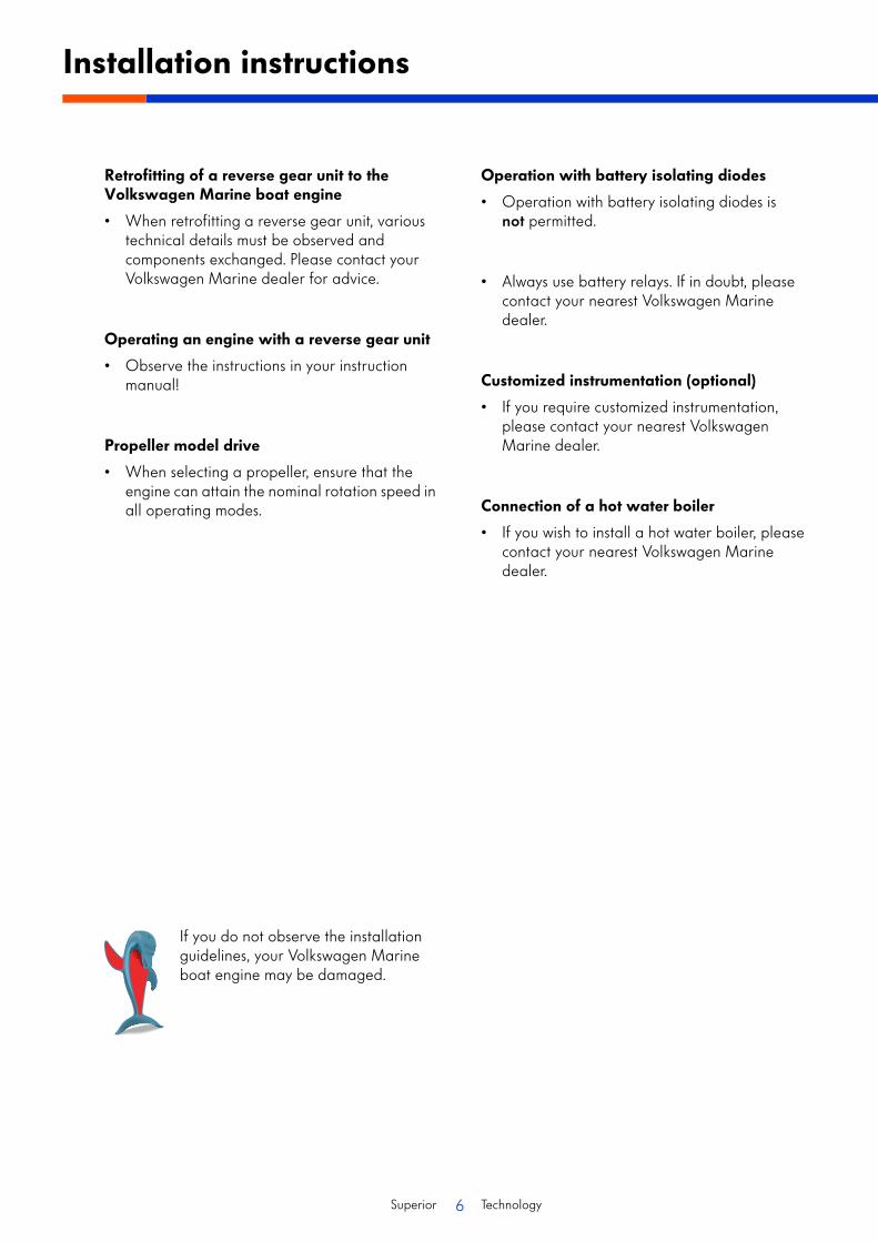
Retrofitting of a reverse gear unit to the Volkswagen Marine boat engine
• When retrofitting a reverse gear unit, various technical details must be observed and components exchanged. Please contact your Volkswagen Marine dealer for advice.
Operating an engine with a reverse gear unit
• Observe the instructions in your instruction manual!
Propeller model drive
• When selecting a propeller, ensure that the engine can attain the nominal rotation speed in all operating modes.
Operation with battery isolating diodes
• Operation with battery isolating diodes is not permitted.
• Always use battery relays. If in doubt, please contact your nearest Volkswagen Marine dealer.
Customized instrumentation (optional)
• If you require customized instrumentation, please contact your nearest Volkswagen Marine dealer.
Connection of a hot water boiler
• If you wish to install a hot water boiler, please contact your nearest Volkswagen Marine dealer.
Installation instructions
If you do not observe the installation guidelines, your Volkswagen Marine boat engine may be damaged.
7Superior Technology
15 c
m
5 cm
10
9
3 4 5 6 7 81 2
11
Exhaust system
Introduction
Volkswagen Marine boat engines are operated using wet exhaust systems.
Note
The water collector (item 4. in the figure) should be dimensioned so that it can accept the total amount of seawater / freshwater that can flow back.
The seawater / freshwater mixes with the exhaust gases, cooling them considerably so that in the remainder of the exhaust system, connection hoses made from rubber and PVC parts, capable of withstanding temperatures up to at least 200 °C, can be used.
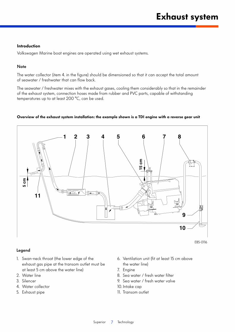
Overview of the exhaust system installation: the example shown is a TDI engine with a reverse gear unit
Legend
1. Swan-neck throat (the lower edge of the exhaust gas pipe at the transom outlet must be at least 5 cm above the water line)
2. Water line3. Silencer4. Water collector5. Exhaust pipe
6. Ventilation unit (fit at least 15 cm above the water line)
7. Engine8. Sea water / fresh water filter9. Sea water / fresh water valve10. Intake cap11. Transom outlet
EB5-0116

8Superior Technology
Notes
• The complete exhaust system should be installed with as few pipe bends as possible.A minimum pipe cross section* of 100 mm must be maintained.
• Hose connections -A- should always be secured with double hose clips.
• Hose connections and rubber sleeves must be temperature-resistant.
* Note:The pipe cross-section for the SDI-Motor may be after consulting VW Marine!
Exhaust gas pressures
The exhaust system should not be made too long, to ensure that the correct maximum value for the exhaust gas counter pressure is not exceeded.
Exhaust gas pressures for particular motor units operating at rated power output:
• SDI 55-5 at 40 kW = 60 mbar
• SDI 75-5 at 55 kW = 150 mbar
• TDI 100-5 at 74 kW = 120 mbar
• TDI 120-5 at 88 kW = 200mbar
• TDI 150-5D at 108 kW = 250mbar
• TDI 150-5 at 111 kW = 250mbar
• TDI 165-5 at 121 kW = 250mbar
Exhaust system
These values should not be exceeded.
EB5-0005
EB5-0086
Legend
1. Screw plug for exhaust gas withdrawal2. Exhaust gas inlet3. Connection for freshwater temperature sensor
(optional)
SDI exhaust pipe connection
9Superior Technology
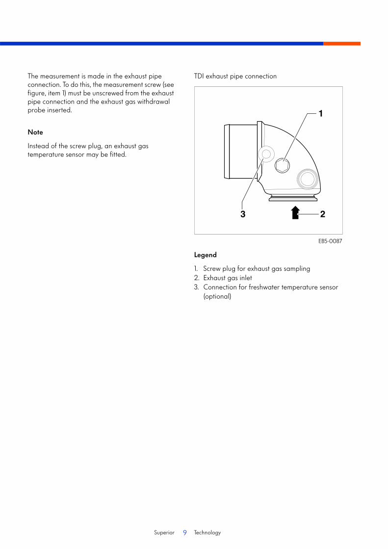
The measurement is made in the exhaust pipe connection. To do this, the measurement screw (see figure, item 1) must be unscrewed from the exhaust pipe connection and the exhaust gas withdrawal probe inserted.
Note
Instead of the screw plug, an exhaust gas temperature sensor may be fitted.
EB5-0087
Legend
1. Screw plug for exhaust gas sampling2. Exhaust gas inlet3. Connection for freshwater temperature sensor
(optional)
TDI exhaust pipe connection
10Superior Technology
1
2
3
4
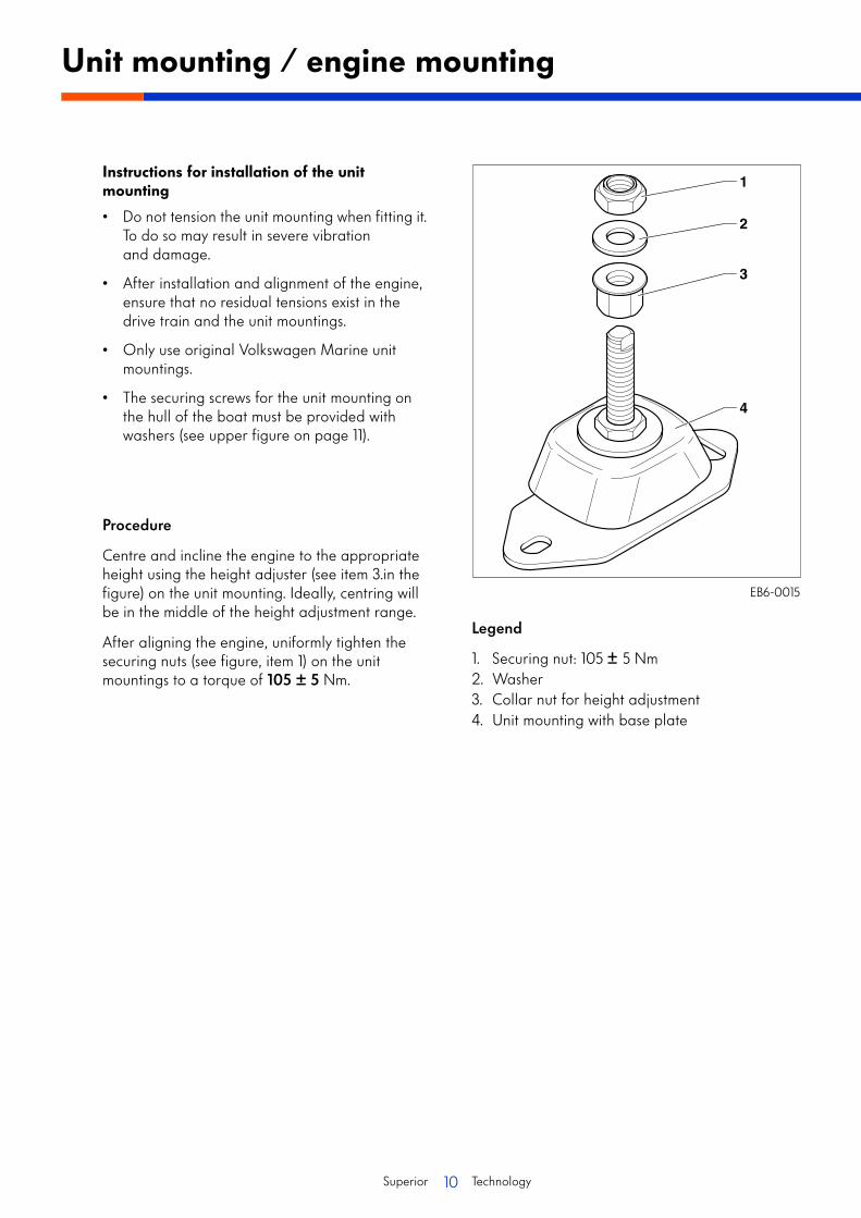
Instructions for installation of the unit mounting
• Do not tension the unit mounting when fitting it. To do so may result in severe vibration and damage.
• After installation and alignment of the engine, ensure that no residual tensions exist in the drive train and the unit mountings.
• Only use original Volkswagen Marine unit mountings.
• The securing screws for the unit mounting on the hull of the boat must be provided with washers (see upper figure on page 11).
Procedure
Centre and incline the engine to the appropriate height using the height adjuster (see item 3.in the figure) on the unit mounting. Ideally, centring will be in the middle of the height adjustment range.
After aligning the engine, uniformly tighten the securing nuts (see figure, item 1) on the unit mountings to a torque of 105 ± 5 Nm.
Unit mounting / engine mounting
EB6-0015
Legend
1. Securing nut: 105 ± 5 Nm2. Washer3. Collar nut for height adjustment4. Unit mounting with base plate

11Superior Technology
4
123 11
0
8
12
Unit mounting dimensions
To prevent sideways turning (twisting) during tightening, the height adjuster -arrow- of the unit mounting / engine mounting must be held (turned in the opposite direction) with a suitable tool (e.g. an open-ended spanner).
To secure the base plate to the boat’s hull, use securing screws with suitable washers.
EB5-0077
EB6-0016
12Superior Technology
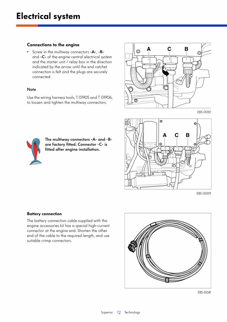
Connections to the engine
• Screw in the multiway connectors -A-, -B- and -C- of the engine central electrical system and the starter unit / relay box in the direction indicated by the arrow until the end ratchet connection is felt and the plugs are securely connected.
Note
Use the wiring harness tools, T 01905 and T 01906, to loosen and tighten the multiway connectors.
Battery connection
The battery connection cable supplied with the engine accessories kit has a special high-current connector at the engine end. Shorten the other end of the cable to the required length, and use suitable crimp connectors.
Electrical system
The multiway connectors -A- and -B- are factory fitted. Connector -C- is fitted after engine installation.
A C B
EB5-0041
EB5-0010
EB5-0009

13Superior Technology
Connect the high current connector -2- of the battery connection cable to the engine connector -1- in the direction shown by the arrow.
Only use high-quality battery terminals for the battery connections.
• Connect the black cable (earth) to the negative pole of the battery.
• Connect the red cable (positive) to the positive pole of the battery.
Safety precautions
Volkswagen Marine recommends the installation of a flat fuse (400 A), immediately prior to the battery connection -see figure-, in the positive cable.
Additionally a battery master switch should be installed in the supply line to enable breaking of the main circuit in cases of danger and when working on the engine.
When fitting the ring terminals to the cable ends (35 mm2) of the battery connection cables, ensure these are correctly fitted with a crimp connection.
EB5-0089
EB5-0012
EB5-0013
14Superior Technology
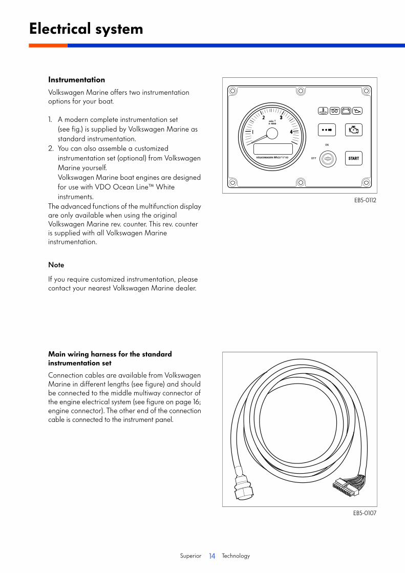
Instrumentation
Volkswagen Marine offers two instrumentation options for your boat.
1. A modern complete instrumentation set (see fig.) is supplied by Volkswagen Marine as standard instrumentation.
2. You can also assemble a customized instrumentation set (optional) from Volkswagen Marine yourself.Volkswagen Marine boat engines are designed for use with VDO Ocean Line™ White instruments.
The advanced functions of the multifunction display are only available when using the original Volkswagen Marine rev. counter. This rev. counter is supplied with all Volkswagen Marine instrumentation.
Note
If you require customized instrumentation, please contact your nearest Volkswagen Marine dealer.
Main wiring harness for the standard instrumentation set
Connection cables are available from Volkswagen Marine in different lengths (see figure) and should be connected to the middle multiway connector of the engine electrical system (see figure on page 16; engine connector). The other end of the connection cable is connected to the instrument panel.
Electrical system
EB5-0112
EB5-0107

15Superior Technology
1
2
Overview of standard instrumentation installation
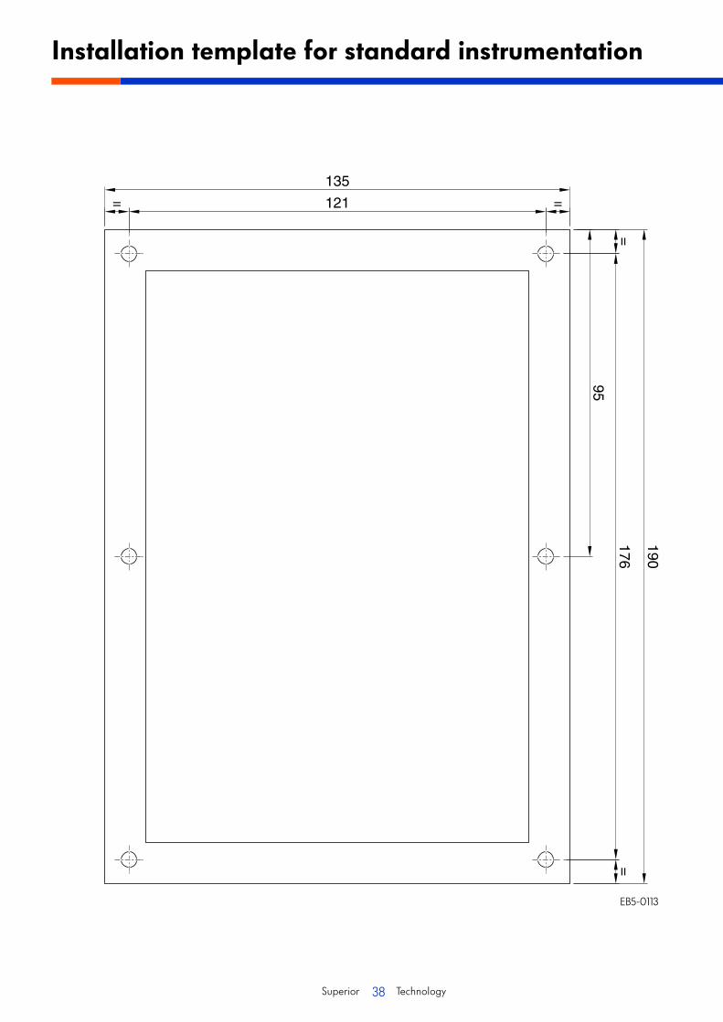
An installation template to be used as a cut-out for fitting the instrumentation, can be found on page 38.
EB5-0108
Legend
1. Instrument panel2. Connector to the central electrical system
16Superior Technology
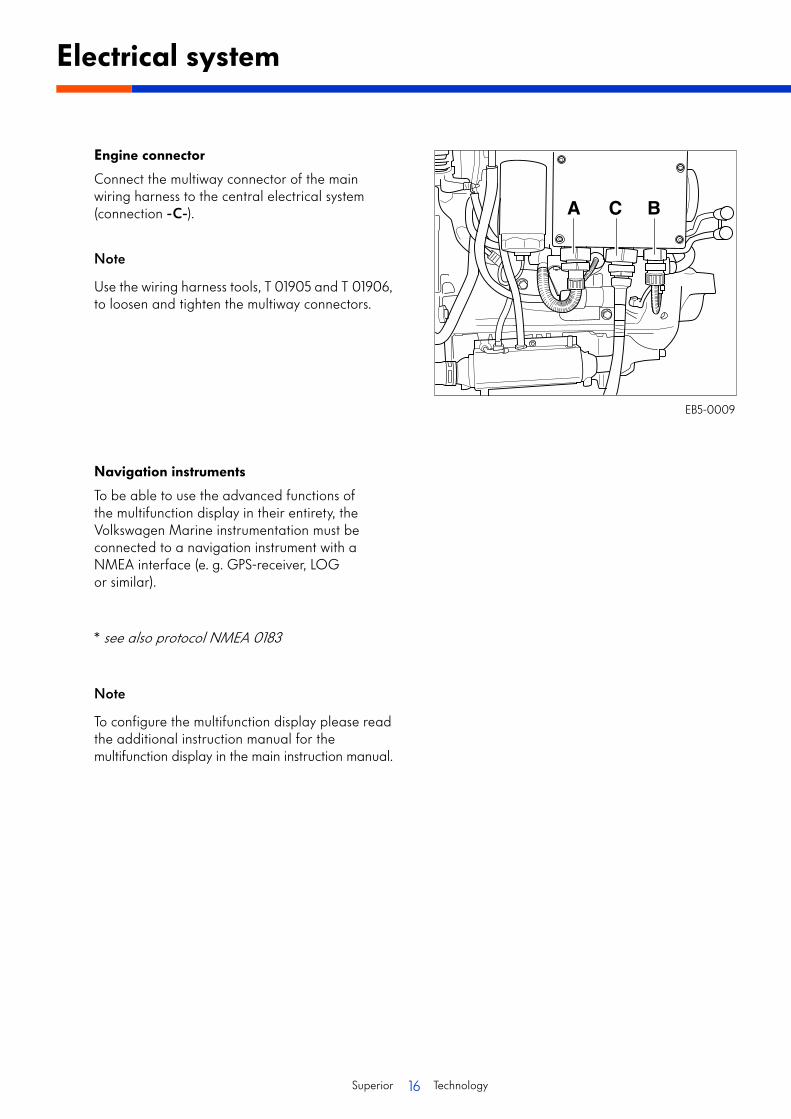
Engine connector
Connect the multiway connector of the main wiring harness to the central electrical system (connection -C-).
Note
Use the wiring harness tools, T 01905 and T 01906, to loosen and tighten the multiway connectors.
Navigation instruments
To be able to use the advanced functions of the multifunction display in their entirety, the Volkswagen Marine instrumentation must be connected to a navigation instrument with a NMEA interface (e. g. GPS-receiver, LOG or similar).
* see also protocol NMEA 0183
Note
To configure the multifunction display please read the additional instruction manual for the multifunction display in the main instruction manual.
Electrical system
A C B
EB5-0009

17Superior Technology
Connection of the standard instrumentation
Terminal strip -A- for the navigation instrument on the rear side of the instrument panel:
1. Neutral2. Neutral Out3. Neutral with flybridge4. D+ cut-off relay5. NMEA-B 6. NMEA-A
Connection variants
Reverse gear unit with simple instrumentation:
Place a bridge between terminals 1 + 2 of the terminal strip.
Reverse gear unit with flybridge:
Place a bridge between terminals 2 +3 of the terminal strip.
Z-drive with simple instrumentation:
Connect the throttle between terminals 1 + 2 of the terminal strip.
Z-drive with flybridgelybridge:
Connect the throttle between terminals 2 +3 of the terminal strip for the flybridge instrumentation.
12
3
45
6
A
EB5-0109
18Superior Technology
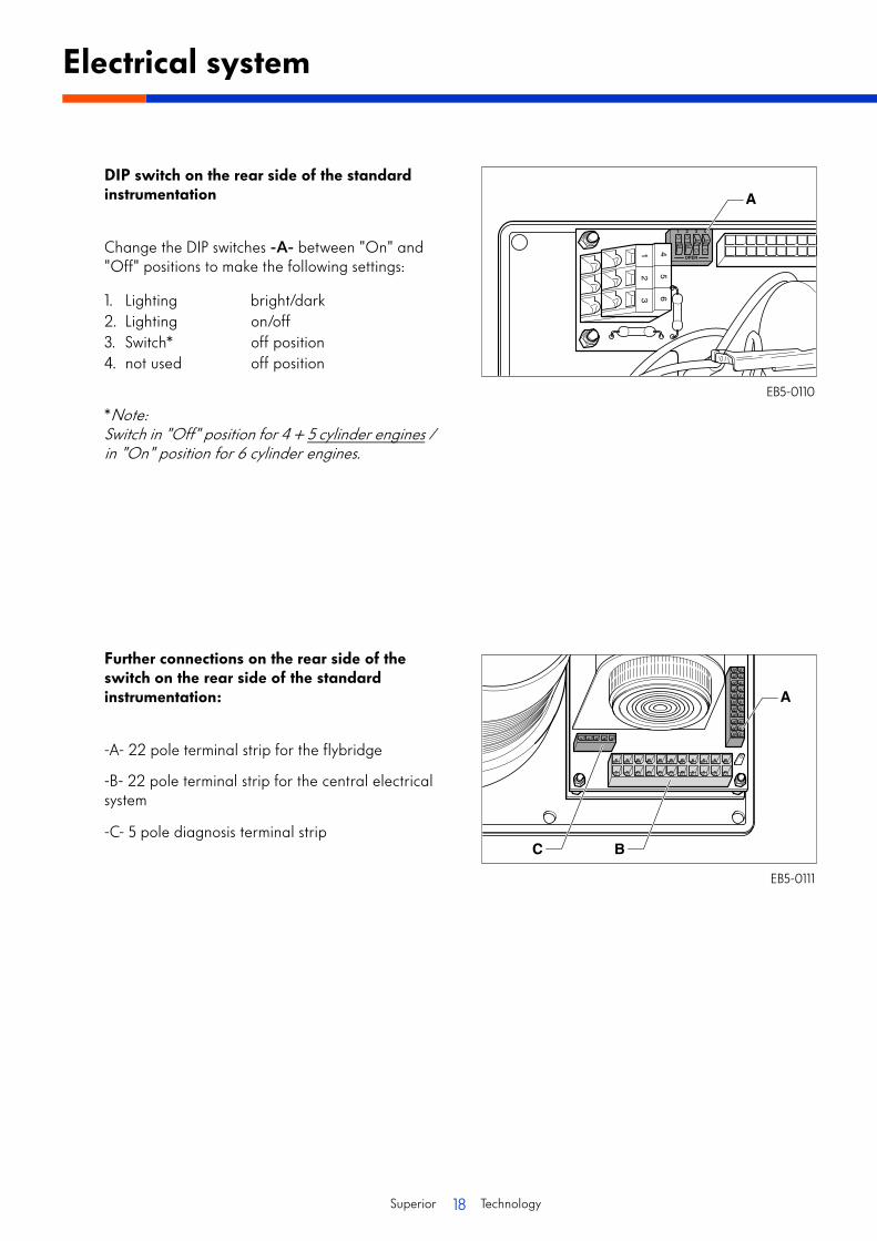
DIP switch on the rear side of the standard instrumentation
Change the DIP switches -A- between "On" and "Off" positions to make the following settings:
1. Lighting bright/dark2. Lighting on/off3. Switch* off position4. not used off position
*Note:Switch in "Off" position for 4 + 5 cylinder engines / in "On" position for 6 cylinder engines.
Further connections on the rear side of the switch on the rear side of the standard instrumentation:
-A- 22 pole terminal strip for the flybridge
-B- 22 pole terminal strip for the central electrical system
-C- 5 pole diagnosis terminal strip
Electrical system
12
3
45
6A
A
C B
EB5-0110
EB5-0111

19Superior Technology
Installation dimensions for the SDI Volkswagen Marine boat engine
Side view
Front view
Engine installation dimensions
EB5-0028SDI engine
EB5-0029SDI engine with auxiliary generator
20Superior Technology
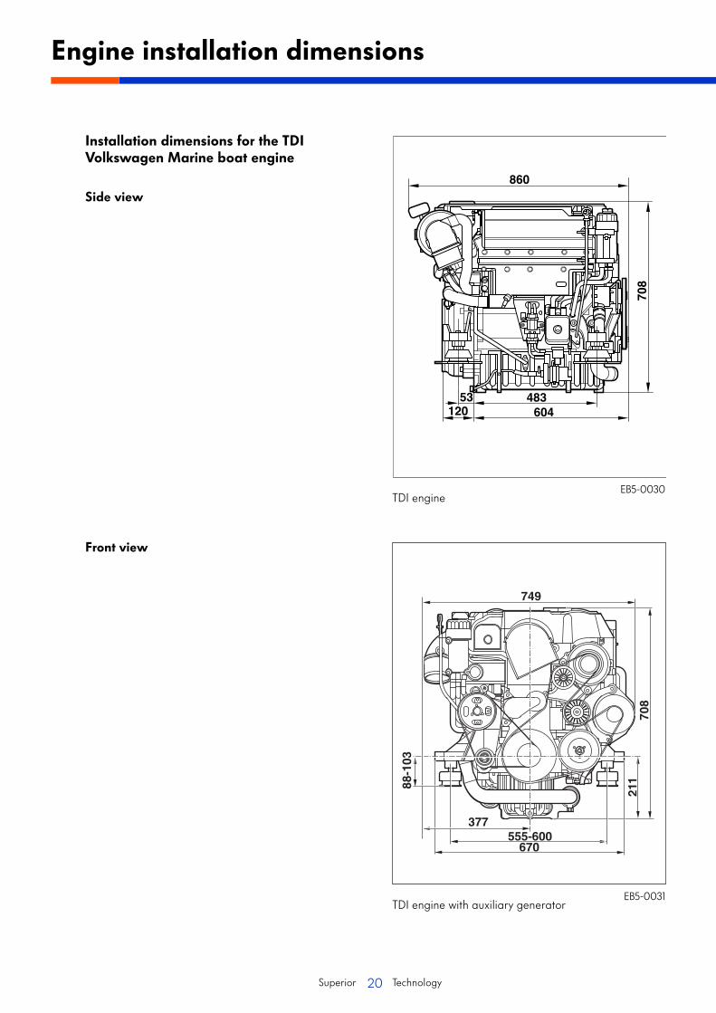
Installation dimensions for the TDI Volkswagen Marine boat engine
Side view
Front view
Engine installation dimensions
749
377555-600
670
88-1
03
211
708
EB5-0030TDI engine
EB5-0031TDI engine with auxiliary generator

21Superior Technology
The following transmission bell housings can be used with Volkswagen Marine boat engines with Z-drive:
1. Transmission bell housing for VOLVO SX/DP-S
2. Transmission bell housing for VOLVO SP-E/DP-E
3. Transmission bell housing for Mercruiser Alpha/Bravo
Transmission bell housing for VOLVO SX/DP-S
Legend
1 - Securing screw 60 Nm
2 - Transmission bell housing
Transmission bell housing for VOLVO SP-E/DP-E
Legend
1 - Securing screw 60 Nm
2 - Transmission bell housing
3 - Bearing
4 - Circlip
5 - Circlip
6 - Seal
7 - Sleeve
8 - Drive shaft
Transmission bell housing for engines with Z-drive
EB5-0054
EB5-0053

22Superior Technology
Transmission bell housing for Mercruiser Alpha/Bravo
Legend
1 - Securing screw 60 Nm
2 - Transmission bell housing
3 - Cup washer
4 - Bearing
Note
TDI engines, 150-5, 150-5D and 165-5 can be ordered from the factory with Mercruiser Bravo I and III drives.
Transmission bell housing for engines with Z-drive
EB5-0052
23Superior Technology
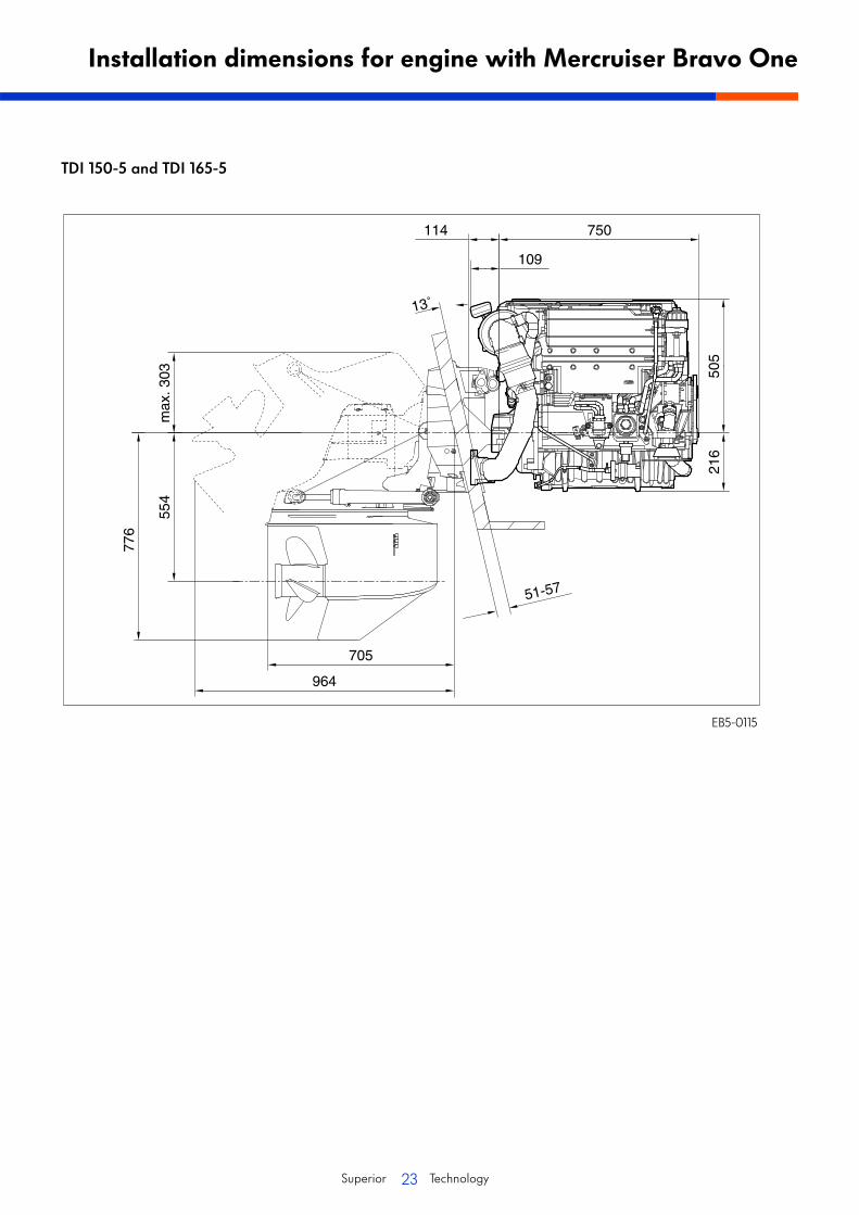
TDI 150-5 and TDI 165-5
Installation dimensions for engine with Mercruiser Bravo One
750
51-57
776
114
109
13˚
505
216
705
554
max
. 303
964
EB5-0115

24Superior Technology
TDI 150-5 and TDI 165-5
Installation dimensions for engine with Mercruiser Bravo Three
750
51-57
791
778
554
max
. 375
851
114
109
13˚
989
505
216
EB5-0114
25Superior Technology
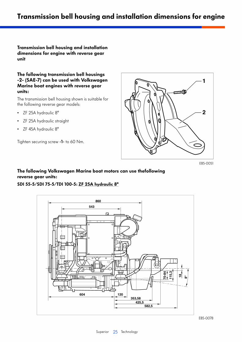
Transmission bell housing and installation dimensions for engine with reverse gear unit
The following transmission bell housings -2- (SAE-7) can be used with Volkswagen Marine boat engines with reverse gear units:
The transmission bell housing shown is suitable for the following reverse gear models:
• ZF 25A hydraulic 8°
• ZF 25A hydraulic straight
• ZF 45A hydraulic 8°
Tighten securing screw -1- to 60 Nm.
Transmission bell housing and installation dimensions for engine
EB5-0051
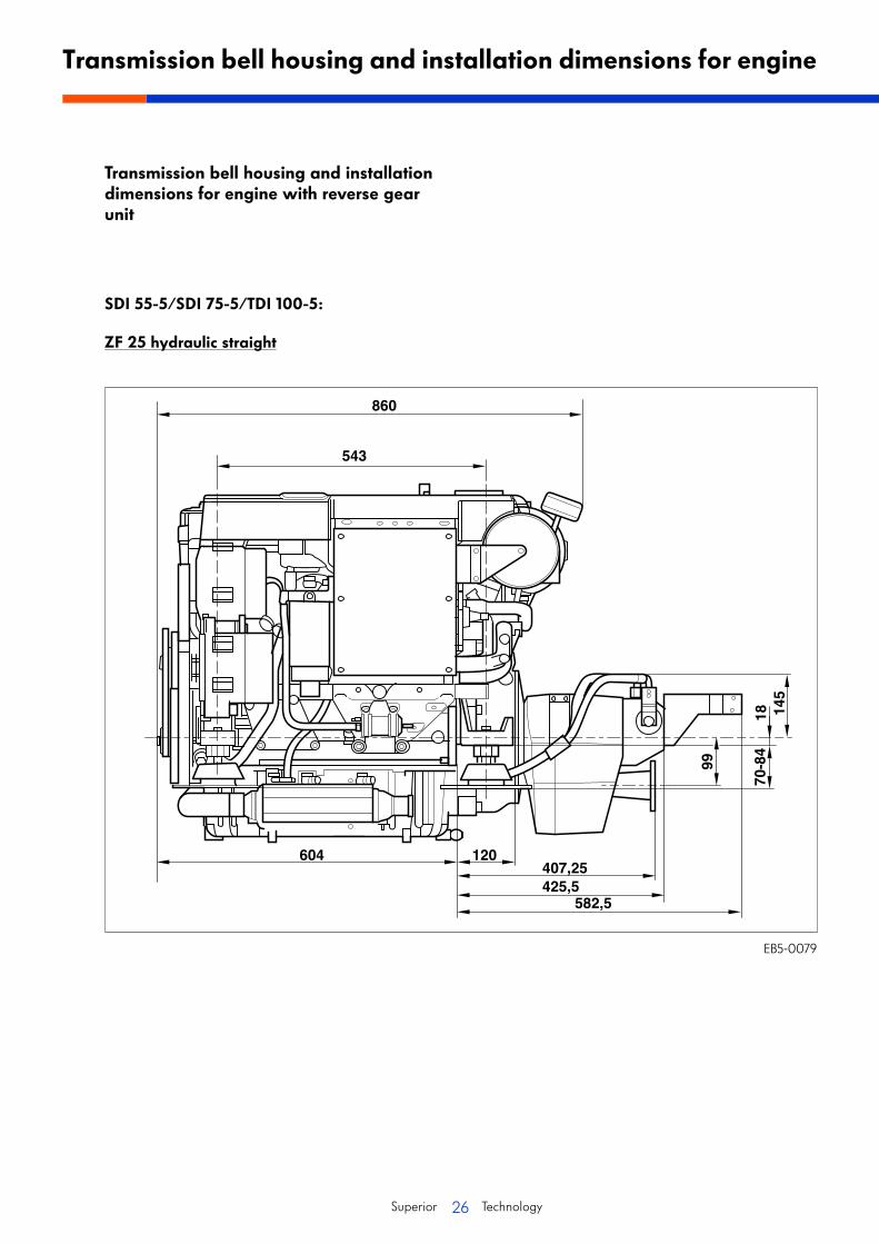
The following Volkswagen Marine boat motors can use thefollowing reverse gear units:
SDI 55-5/SDI 75-5/TDI 100-5: ZF 25A hydraulic 8°
EB5-0078
26Superior Technology
Transmission bell housing and installation dimensions for engine with reverse gear unit
SDI 55-5/SDI 75-5/TDI 100-5:
ZF 25 hydraulic straight
Transmission bell housing and installation dimensions for engine
EB5-0079

27Superior Technology
TDI 120-5/TDI 150-5/TDI 150-5D/TDI 165-5:
ZF 45A hydraulic 8°
EB5-0080

28Superior Technology
Cooling system
Introduction
To maintain the engine free from aggressive media such as salt water, Volkswagen Marine boat engines have a twin-circuit cooling system.
The internal engine coolant circuit is a closed system and is mixed with antifreeze (G12).
The seawater /freshwater circuit, also called the secondary circuit, is an open circuit in which the seawater / freshwater is sucked in and, after flowing through the heat exchanger, fed back to the outside again via the exhaust system.
Coolant circuitExample: SDI engine
EB5-0093
Legend
1. Exhaust manifold2. Main heat exchanger3. Exhaust collector4. Coolant expansion tank5. Oil cooler6. Thermostat 70 °C
7. Engine8. Radiator element housing9. Sea water / fresh water pump10. Combined cooler11. Sea water / fresh water filter
29Superior Technology
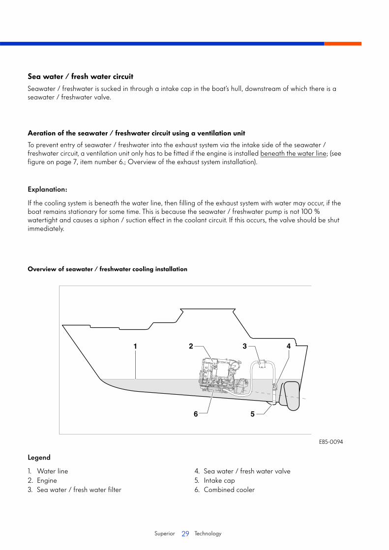
Sea water / fresh water circuit
Seawater / freshwater is sucked in through a intake cap in the boat’s hull, downstream of which there is a seawater / freshwater valve.
Aeration of the seawater / freshwater circuit using a ventilation unit
To prevent entry of seawater / freshwater into the exhaust system via the intake side of the seawater / freshwater circuit, a ventilation unit only has to be fitted if the engine is installed beneath the water line; (see figure on page 7, item number 6.; Overview of the exhaust system installation).
Explanation:
If the cooling system is beneath the water line, then filling of the exhaust system with water may occur, if the boat remains stationary for some time. This is because the seawater / freshwater pump is not 100 % watertight and causes a siphon / suction effect in the coolant circuit. If this occurs, the valve should be shut immediately.
Overview of seawater / freshwater cooling installation
EB5-0094
Legend
1. Water line2. Engine3. Sea water / fresh water filter
4. Sea water / fresh water valve5. Intake cap6. Combined cooler
30Superior Technology
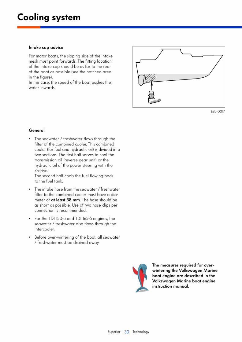
Intake cap advice
For motor boats, the sloping side of the intake mesh must point forwards. The fitting location of the intake cap should be as far to the rear of the boat as possible (see the hatched area in the figure).In this case, the speed of the boat pushes the water inwards.
General
• The seawater / freshwater flows through the filter of the combined cooler. This combined cooler (for fuel and hydraulic oil) is divided into two sections. The first half serves to cool the transmission oil (reverse gear unit) or the hydraulic oil of the power steering with the Z-drive.The second half cools the fuel flowing back to the fuel tank.
• The intake hose from the seawater / freshwater filter to the combined cooler must have a dia-meter of at least 38 mm. The hose should be as short as possible. Use of two hose clips per connection is recommended.
• For the TDI 150-5 and TDI 165-5 engines, the seawater / freshwater also flows through the intercooler.
• Before over-wintering of the boat, all seawater / freshwater must be drained away.
Cooling system
EB5-0017
The measures required for over-wintering the Volkswagen Marine boat engine are described in the Volkswagen Marine boat engine instruction manual.
31Superior Technology
Fuel system
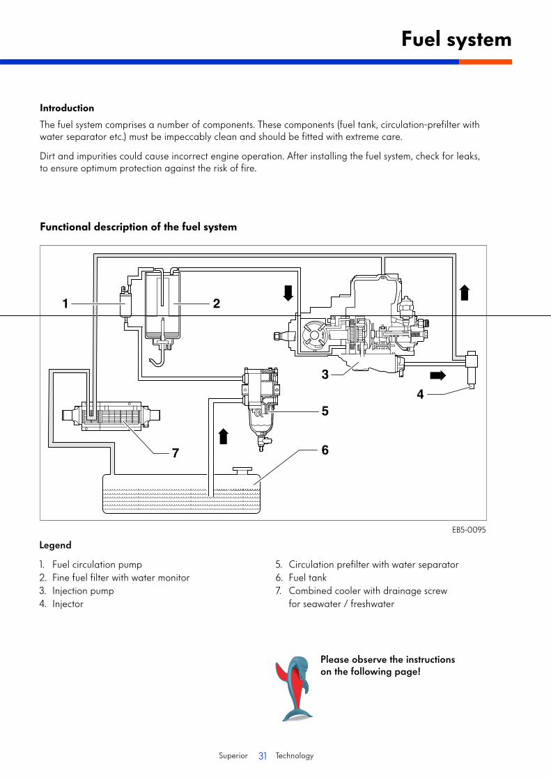
Introduction
The fuel system comprises a number of components. These components (fuel tank, circulation-prefilter with water separator etc.) must be impeccably clean and should be fitted with extreme care.
Dirt and impurities could cause incorrect engine operation. After installing the fuel system, check for leaks, to ensure optimum protection against the risk of fire.
Functional description of the fuel system
EB5-0095
Legend
1. Fuel circulation pump2. Fine fuel filter with water monitor3. Injection pump4. Injector
5. Circulation prefilter with water separator6. Fuel tank7. Combined cooler with drainage screw
for seawater / freshwater
Please observe the instructions on the following page!
32Superior Technology
Fuel system
• The compartment containing the fuel system must be sufficiently ventilated. Fuel tank and filler cap must have an earth connection to the battery (for steel boats to the hull).
• When arranging the components, ensure that there is sufficient clearance for any future maintenance and repair work.
• The fuel supply line is to be routed from the fuel tank via the circulation prefilter and water separator. The line cross section must be at least 8 mm.
• A fuel return line is to be routed from the combined cooler to the fuel tank.The line cross section must be at least 8 mm.
• The return line from the fuel injection pump to the combined cooler is fitted in the factory.
• Your Volkswagen Marine boat motor is approved for use with RME fuel (rapeseed oilmethyl ester / biodiesel).
Note
If you intend using RME fuel (rapeseed oil methyl ester / biodiesel), then all auxiliary fuel lines, seals and other connections to the engine must be suitable for use with RME fuel (see technical data on page 36).
33Superior Technology
Introduction
Engine compartment ventilation
• The engine must be sufficiently ventilated to ensure that the temperature can be maintained at an optimum value, that is as low as possible.(∆Tmax. above ambient temperature: 10 °C to 15 °C).
• To ensure optimum engine compartment ventilation, the air inlet should be placed where the sucked-in air is as clean as possible and where the engine's own exhaust gases cannot be sucked in.
• Water must not be able to enter either the air inlet or the air outlet.
• The hydraulic cross section for the air inlet must equal 80 cm2.
• If other equipment that requires oxygen for its operation (e.g. an auxiliary heater) is located in the engine compartment, then this must also be considered when dimensioning the air inlet.

34Superior Technology
15
14
13
12 11 10
9
8
7
6
5
2 3 41
Engine components list
Legend
1. Coolant sealing cap (use coolant G12, colour red)
2. Step plate3. Cover (tighten securing screw to 4.5 Nm)4. Central electrical system5. Stop switch6. Alternator7. Fine fuel filter (see instruction manual
for replacement intervals)
8. Ribbed V-belt9. Combined cooling unit10. Unit mounting11. Power steering pump12. Tensioner13. Ribbed V-belt14. Tensioner15. Belt pulley for sea water / fresh water pump
EB5-0082

35Superior Technology
EB5-0085Legend
1. Turbocharger pressure unit2. Suspension eye3. Radiator element housing4. Dipstick5. Oil filter6. Sea water / fresh water pump7. Oil cooler8. Oil extraction pump
9. Oil sump10. Engine connector11. Transmission bell housing12. Coolant drain screw13. Sacrificial anode14. Water level sender15. Exhaust pipe connection16. Turbocharger
36Superior Technology
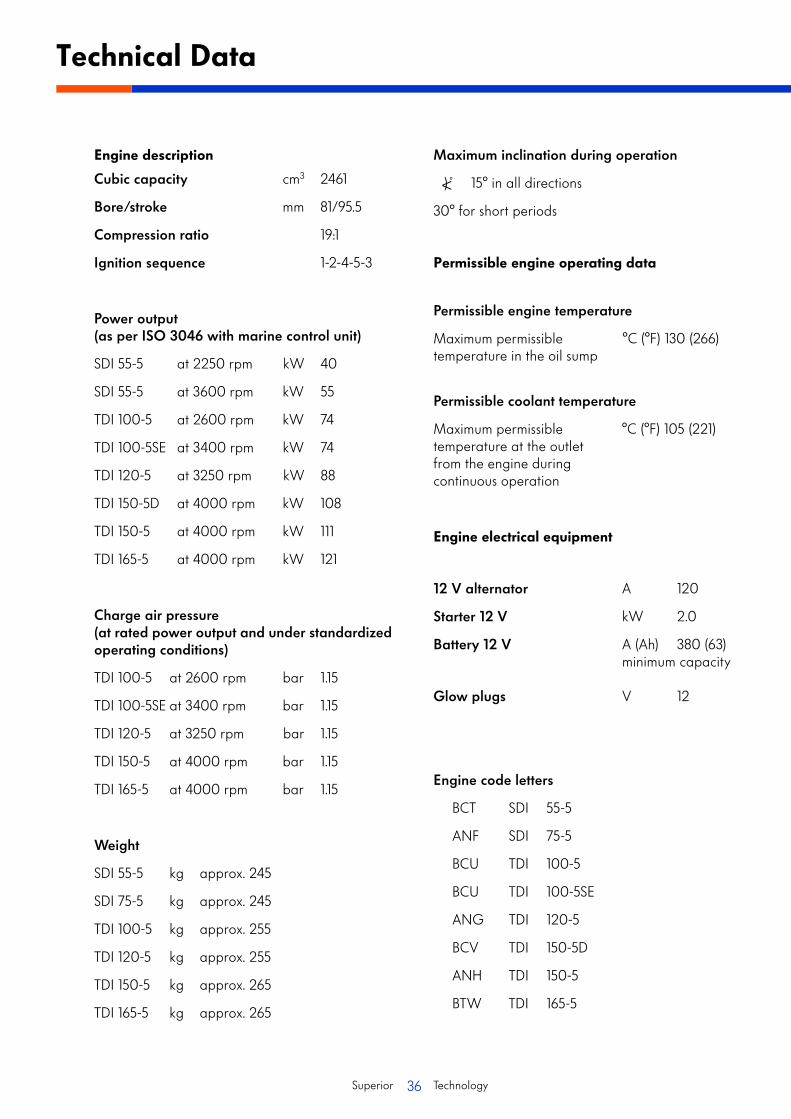
Engine description
Cubic capacity cm3 2461
Bore/stroke mm 81/95.5
Compression ratio 19:1
Ignition sequence 1-2-4-5-3
Power output(as per ISO 3046 with marine control unit)
SDI 55-5 at 2250 rpm kW 40
SDI 55-5 at 3600 rpm kW 55
TDI 100-5 at 2600 rpm kW 74
TDI 100-5SE at 3400 rpm kW 74
TDI 120-5 at 3250 rpm kW 88
TDI 150-5D at 4000 rpm kW 108
TDI 150-5 at 4000 rpm kW 111
TDI 165-5 at 4000 rpm kW 121
Charge air pressure(at rated power output and under standardized operating conditions)
TDI 100-5 at 2600 rpm bar 1.15
TDI 100-5SE at 3400 rpm bar 1.15
TDI 120-5 at 3250 rpm bar 1.15
TDI 150-5 at 4000 rpm bar 1.15
TDI 165-5 at 4000 rpm bar 1.15
Weight
SDI 55-5 kg approx. 245
SDI 75-5 kg approx. 245
TDI 100-5 kg approx. 255
TDI 120-5 kg approx. 255
TDI 150-5 kg approx. 265
TDI 165-5 kg approx. 265
Maximum inclination during operation
15° in all directions
30° for short periods
Permissible engine operating data
Permissible engine temperature
Maximum permissible °C (°F) 130 (266)temperature in the oil sump
Permissible coolant temperature
Maximum permissible °C (°F) 105 (221)temperature at the outlet from the engine during continuous operation
Engine electrical equipment
12 V alternator A 120
Starter 12 V kW 2.0
Battery 12 V A (Ah) 380 (63)minimum capacity
Glow plugs V 12
Engine code letters
BCT SDI 55-5
ANF SDI 75-5
BCU TDI 100-5
BCU TDI 100-5SE
ANG TDI 120-5
BCV TDI 150-5D
ANH TDI 150-5
BTW TDI 165-5
<) °
Technical Data

37Superior Technology
Cooling system
Twin circuit cooling system (overpressure system with separate expansion tank and overpressure valve) and seawater / freshwater circuit with impeller pump.
Overpressure valve
Opens at bar (overpressure) 1.3 – 1.5
Thermostat
Starts opening at °C (°F) 70 (158)
Coolant
Use a mixture of 60% water and 40% G12 antifreeze as per TL VW 774D.
Fuel
Fuel diesel as per DIN EN 590
Required minimumcetane number CN > 51
Biodiesel as per EN 51 606
Diameters / Line cross sections
Exhaust system Ø 100 mm
Intake hose for sea water / freshwater Ø 38 mm
Fuel lines Ø 8 mm
Battery connection cable 35 mm2
Oil supply
Engine oil quality
Oil type VW Marine Longlife, oil specification VW 505 00 (see also instruction manual information)
Oil pressure
At 2000 rpm and 80 °C (176 °F) engine oil temperature (overpressure) at least 2.0
Oil consumption
(maximum permitted) l/10 h 0.05 - 0.1
Filling quantities
Coolant circuit ltr. approx. 12
Oil circuit
Including filter change ltr. 6.0
Volume differencebetween min. andmax. markings on the dipstick ltr. approx. 1.0
38Superior Technology
Installation template for standard instrumentation
95
=176
=
190
=121=
135
EB5-0113

39Superior Technology
Installation description EB05
© 2006 Volkswagen Marine
Text, figures and standards in this guide are based on information current at the time of printing. Reprinting, reproduction or translation, in whole or in part, is not permitted without the written approval of Volkswagen Marine. All rights according to the applicable copyright laws are expressly reserved for Volkswagen Marine. Subject to alterations.Copy date 03/06
Postfach 31 11 76, 38231 SalzgitterEdition 03/06 print number 065.991.EB05.20
❀ This paper was produced from wood pulp bleached without chlorine.