boat #4 - solar splashsolarsplash.com/wp-content/uploads/2014/10/2014_stony_brook_ss...the steering...
TRANSCRIPT

Boat #4
TEAM MEMBERS Ankit Tyagi Han John Tse
Dominic Silva Dominick Fratto Mohammed Uddin Philip Mauser
Kevin Thorp Andy Chu
Cameron Simmonds Nicholas Allen
PRIMARY FACULTY ADVISOR David Hwang SECONDARY FACULTY ADVISOR David Westerfeld
May 5th, 2014

ii
EXECUTIVE SUMMARY
The goals of this year’s Stony Brook Solar Boat Team are to improve upon its performance at the IEEE Power Electronics Society’s Solar Splash 2014 and compete against other teams at the event. The team was subcategorized into three groups (1) Electrical Engineering (EE), (2) Mechanical Engineering (ME), and (3) Composites (CP). This year, the team decided to once again use the hull from previous years which is manufactured out of carbon fiber. The dry weight of the hull is 30 lbs., making it the lightest hull in the history of Stony Brook Solar Boat Team.
The EE group was in charge of electrical aspects of this board. This covered a broad area of skill sets as it involved power distribution from our solar panels to other subsystems as well as embedded system design. This year, the electrical team focused on implementing a DAQ system that displays feedback data values from a tachometer and the motor controller to an LCD screen. Additionally, two motor controllers were utilized this year (as opposed to one in 2013) to increase the current input to the motors. The reason in doing so was to compensate for the increase in the gear ratio in the drivetrain.
The ME group overlooked the mechanical aspects of the boat, consisting of the drive train, propeller selection, coupling of motors, steering system, and boat assembly. Based on the success of the previous year’s performance, the Arneson surface piercing drivetrain design was once again used, only with a shorter propeller shaft. This design change was chosen to reduce weight, drag, and improve handling. As mentioned before, a set of gear ratios (1:1 and 1:1.5) are introduced in the drivetrain assembly. Failures from last year’s performance were taken into design considerations and implemented in this year’s drivetrain.
The CP group was in charge of designing and manufacturing two 1:4 scale models of new hull designs that will potentially be used in upcoming Solar Splash events. This required the group to first produce a plug, then a fiber glass mold, and finally the finished carbon fiber hull that would be used for testing. Testing was held at Davidson Laboratory located at Stevens Institute of Technology in New Jersey. There, a 300 foot towing tank was utilized to test the scale models for drag, trim, and the ability to plane at various speeds. This project gave new members to learn and acquire carbon fiber tooling skills necessary for building next year’s hull.

iii
Contents
EXECUTIVE SUMMARY ....................................................................................................................................... ii
CURRENT DESIGN (2012-13) .......................................................................................................................... 1
Problems with the Design ............................................................................................................................. 3
DESIGN CONCEPTS ............................................................................................................................................... 4
HULL ...................................................................................................................................................................... 4
MECHANICAL SYSTEMS ................................................................................................................................ 5
ELECTRICAL SYSTEMS ................................................................................................................................... 5
DESIGN DESCRIPTION ........................................................................................................................................ 8
HULL ...................................................................................................................................................................... 8
MECHANICAL SYSTEMS ................................................................................................................................ 9
DESIGN EVALUATION ...................................................................................................................................... 12
HULL ................................................................................................................................................................... 12
MECHANICAL SYSTEMS ............................................................................................................................. 12
ELECTRICAL SYSTEMS ................................................................................................................................ 15
TESTING PROCEDURES AND RESULTS ..................................................................................................... 15
Discussion ........................................................................................................................................................ 15
PROJECT MANAGEMENT ................................................................................................................................ 16
Team Member Organization and Responsibilities ........................................................................... 16
Project Planning and Schedule ................................................................................................................. 16
Financial and Fund Raising ....................................................................................................................... 16
Strategy for Team Continuity and Sustainability .............................................................................. 16
CONCLUSION ....................................................................................................................................................... 17

iv
REFERENCES ....................................................................................................................................................... 18
APPENDIX A: BATTERY DOCUMENTATION ........................................................................................... 19
APPENDIX B: FLOTATION CALCULATIONS ............................................................................................. 26
APPENDIX C: PROOF OF INSURANCE ........................................................................................................ 27
APPENDIX D: DOCUMENTATION FOR COMMERCIAL MOTOR CONTROLLER .......................... 28
APPENDIX E: DATASHEET FOR SOLAR CHARGER ............................................................................... 31
APPENDIX F: SPECIFICATIONS FOR SOLAR CELLS .............................................................................. 33
APPENDIX G: PICTURES FROM DRAG TESTING OF PLANING HULL PROTOTYPES ............... 35
APPENDIX H: SPLINE COUPLER FINITE ELEMENT ANALYSIS........................................................ 37
Description ........................................................................................................................................................... 37
Assumptions ........................................................................................................................................................ 38
Model Information ............................................................................................................................................. 38
Study Properties ................................................................................................................................................. 39
Units ........................................................................................................................................................................ 39
Material Properties ........................................................................................................................................... 40
Loads and Fixtures ............................................................................................................................................ 40
Mesh Information .............................................................................................................................................. 41
Mesh Information - Details ............................................................................................................................. 41
Sensor Details ...................................................................................................................................................... 42
Resultant Forces ................................................................................................................................................. 42
Reaction Forces ................................................................................................................................................... 42
Reaction Moments ............................................................................................................................................. 42
Study Results ....................................................................................................................................................... 43
APPENDIX I: FINITE ELEMENT ANALYSIS (PROPELLER SHAFT) .................................................. 46
Description ........................................................................................................................................................... 46
Assumptions ........................................................................................................................................................ 47
Model Information ............................................................................................................................................. 47
Study Properties ................................................................................................................................................. 48
Units ........................................................................................................................................................................ 48
Material Properties ........................................................................................................................................... 49

v
Loads and Fixtures ............................................................................................................................................ 50
Connector Definitions ...................................................................................................................................... 51
Contact Information .......................................................................................................................................... 51
Mesh Information .............................................................................................................................................. 52
Mesh Information - Details ............................................................................................................................. 52
Mesh Control Information: ............................................................................................................................. 53
Sensor Details ...................................................................................................................................................... 54
Resultant Forces ................................................................................................................................................. 54
Reaction Forces ................................................................................................................................................... 54
Reaction Moments ............................................................................................................................................. 54
Beams ..................................................................................................................................................................... 54
Study Results ....................................................................................................................................................... 55

1
CURRENT DESIGN (2012-13)
Hull In 2013, the team used the same hull that was built in 2012. This hull was designed to have a displacing deep V profile and was fabricated completely from carbon fiber, with reinforcements of honeycomb foam and plywood. This resulted in a strong yet light hull, resistant to exterior damage. The hull is 12 feet (ft) long and 3 feet (ft) wide and its dry weight is 30 pounds (lbs). These factors contributed towards the boat’s enhanced performance in the endurance and the slalom races, where sharp turns were a necessity.
Figure 1: 2012-2013 Hull
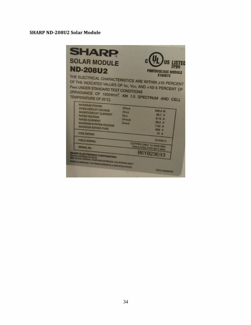
Solar Array The solar panels utilized in 2013 included a set of two Kyocera KC50T modules and a Sharp ND-208U2 module. Each of these modules were connected in series and produced a total of 316 Watts (W). A Tri-Star Maximum Power Point Tracking Solar Controller was utilized to efficiently recharge the battery bank in the boat. The system voltage range on the solar controller varied from 12 to 48 volts (V) allowing for multi-configuration battery charging.
Drivetrain In 2013, the drivetrain design was based on the idea very similar to Arneson surface drive system that is used on many race boats. This design appealed to the team since it was relatively simple and could be kept very light with the rotational inertia as well as be very strong to handle large amount of torque produced by motors. The main components that allowed for implementing such a design were a Constant Velocity (CV) joint and two Lynch Permanent Magnet (PM) DC brushed motors. A chain drive with a gear ratio of 1:1 was utilized for transmitting the torque from the motors to another shaft (lower shaft), which was coupled to the CV joint through a driveshaft with two universal joints (U-joints) at each end. The U-joints compensated for the misalignment of the collinearly of the lower shaft and the CV joint.

2
Figure 2: Motor and driveshaft assembly
Propeller A two-blade custom-made stainless steel solar boat propeller was used by the team to focus mainly on the endurance heat of the competition.
Steering System The steering system of the 2012-13 boat based on a gimbal housing that allowed for two degrees of freedom of the propeller shaft of the drivetrain, allowing for the movement of the propeller while driving. For controlling the steering, a hydraulic piston cylinder was utilized which was controlled by the user through a steering wheel. As the steering wheel would be turned left/right, a hydraulic reservoir would push/pull the hydraulic fluid resulting in pushing/pulling of the stroke connecting rod of the piston cylinder. This movement of the connecting rod governed the turning of the propeller shaft, pivoting at the gimbal assembly.
Figure 3: Gimbal Housing Assembly

3
Electronic Control System The electronic control system consisted of a Curtis 1205 DC motor control system. The motor controller was capable of switching 400 Amperes (A) of current at a voltage range from 24 V to 36 V DC. A 5 kilo-Ohm (kΩ) potentiometer was used for controlling the signal being sent to the motor controller for drawing the appropriate amount of current from the battery bank to power the motors.
Batteries In 2012-13, D1200 AGM deep cycle batteries from XS power were used for the competition. Each battery weighed 33.26 pounds (lb) and had a capacity of 44 Ampere hours (A-Hr), with the maximum current being 2600 A. The sprint configuration consisted of three such batteries in series, making a system voltage of 36 V and the endurance configuration made use of two such batteries, making the system voltage to 24 V. The self-consumption current and voltage ratings were 20 mA and 9 V, respectively, allowing for a low theoretical power loss from the solar panels of 0.18 W.
Problems with the Design In the year of 2012-13, the Solar Boat Team performed relatively well compared to the past few years, attributing to the new drivetrain design. However, even after a radical redesign, the team observed some flaws that needed upgrades. The main encountered problems were:
Modification of the CV cup of the CV joint proved to be disastrous as machining the case hardening diminished the material’s strength. As a result, the cup would heat up undergoing high RPMs in the multiple heats at the competition.
A two-part epoxy was used to attach the trim rod mount on the propeller shaft housing tube. Unreliability of the epoxy against weathering (water) resulted in the failure of the trim mount from the housing tube, detaching the trim rod from the drivetrain.
The low current capacity of the motor controller also played a key role in the boat’s low maximum speed. The motor controller could only extract 400 A from the batteries, resulting in a reduced performance of the propeller.

4
DESIGN CONCEPTS
HULL The objective of this year’s hull/composites team was to design a new hull for next year’s competition (2015) and learn tooling techniques for making carbon fiber parts. This year’s hull is the same as the previous year. The hull developed by the 2011-12 team was fabricated completely from carbon fiber, with reinforcements of honeycomb foam and plywood. The hull has a 3 core 3 cross section, or 3 carbon fiber layers, a honeycomb core, and then 3 more carbon fiber layers on the other side. The deep V shape provides more stability to the boat and enhances its performance in carved turns. The intent in designing this hull was to increase its performance in the endurance heat at the competition. However during the past two competitions, the hull was an inappropriate application to sprint heats because of its large wetter surface area. This resulted in the production of enhanced drag, reducing the boat’s speed. Due to the V shape, the wake of the boat also was intermixed with the effects of propeller backwash, contributing to the reduction of the maximum boat speed. Using the carbon fiber techniques learned from making the hull models.
Since it takes time and effort to design and build a carbon fiber monocoque hull, the team collectively decided to spend this year’s efforts in designing, evaluating and testing of prototype hulls. Research began last summer in July 2013 after the solar splash competition for redesigning a new hull. The first step involved researching what types of hull are most suitable for an electric boat running on two batteries with speed and maneuverability. Factors that contributed towards the designing of the hull were the weight of the boat, the maximum speed necessary to achieve planing, and stability. With the current solar and electrical system design, the boat is estimated to achieve a top speed of about 20 miles per hour (mph), which is well below any top safety speed for planing hulls. At the same time, 20 miles per hour is not very fast, so planing under 20 mph was another design consideration. A Computer Aided Designing and Engineering (CAD/CAE) software was utilized to build computer models of different hulls. The same software was utilized to run flow simulations to analyze water streamlines around the hulls and determine drag and lift. After running tests on several models, we chose the best two models based on the least drag and largest lift.
Figure 4: Solidworks CFD Simulation flow lines on one of the prototype hulls

5
MECHANICAL SYSTEMS
Drivetrain This year’s drivetrain design concept incorporates implementing a dual gear ratio of 1:1 and 1:1.5 in the surface piercing drivetrain from last year. The main purpose in doing so is to account for both aspects of the competition, i.e., endurance and sprint, respectively. Another major feature that is different from last year is the length of the propeller shaft. Compared to last year’s propeller shaft, this year’s design allows the propeller to sit closer to the hull, minimizing loss of energy along the length of the shaft. The advantage of using a chain drive and gear ratios is that it is simple to implement and allows an easy change of gears just by changing the chain from one set of gears to the other. The surface piercing drive train possesses some of design aspects of inboard and outboard drive trains. The key aspect of this design is that half of the propeller is underwater so there is minimum drag from the propeller. A 15% to 30% increase in speed over other systems, low maintenance, and ability to adjust propeller submergence while underway are some of the pros of this design. The system's ability to make tight turns along with efficient speed will definitely give Stony Brook Solar Boat Team an edge.
Steering System This year the team opted for a similar design as last year’s which incorporates a hydraulic fluid reservoir transmitting motion through a piston cylinder. Last year’s piston cylinder stroke was 12 inches long that slowed down the steering turning on the wheel. This year, a cylinder with a shorter stoke (3 inches) will be utilized which will allow for a more sensitive steering turning. The concept of this steering system is based on the method of controlling a steering design using a hydraulic piston being actuated via manual pressurization of hydraulic lines. The major advantage of using this design is that it does not require power and is a relatively simple system to build and maintain.
ELECTRICAL SYSTEMS
Motor Controllers This year’s motor configuration set up is something that the team has been striving to achieve over the past few years, however, the monetary funds has prohibited us to do so. This year, we purchased two new Alltrax motor controllers that each draw continuous 400 A. When put in parallel configuration, the controllers can draw a total of 800 A continuous, however, that is very ambitious to achieve at the current battery limitations. Also as a precautionary measure, we will limit ourselves in not extracting a total of 800 A in a setting as that will drain the batteries faster. We currently use Lynch Permanent Magnet DC brushed motors that appropriately fit this setup easily.

6
Figure 5: Wiring Diagram for the Motor Controller Configuration
Designing of motor controller is still a big field of research and also a big learning field for undergraduate electrical engineering students. Over the years, the team has been working on prototyping a motor controller but hasn’t successfully tested it yet. Sensors and DAQ We have been lacking DAQ systems in our boat for the last few competitions, so this year we decided to design a few sensor-feedback systems for the other systems on the boat. An infrared sensor based tachometer has been designed using an Arduino-Uno based microcontroller that will keep record of the RPMs of the motors.
Figure 6: Wiring Diagram for the Tachometer
Other feedback sensor based outputs from the motor controller can be extracted through a Serial COM port in the motor controller through an Arduino and the data can be printed on an LCD screen.

7
Solar Panels Three commercial solar panels will be connected in series which will produce a total of 316 W. A Tri-Star Maximum Power Point Tracking Solar Controller will be utilized to efficiently recharge the battery bank in the boat. The system voltage range on the solar controller varied from 12 to 48 volts (V) allowing for multi-configuration battery charging.

8
DESIGN DESCRIPTION
HULL The processes involved with building 1/4th scale hull models out of carbon fiber were great learning curves for the team this year. There were several options available to build the model molds. The hull cross sections were plotted on paper and then cut on pieces of economical MDF board. This, along with the wooden dowels holding the cross sections became the skeleton of the hull. We used Styrofoam to fill the voids in between the cross sections and then sanded down the surfaces until they were smooth. A custom hot wire cutter was built that made cutting the Styrofoam easy. Intense bodywork was done until a smoother surface finish was obtained. To make the mold out of tis plug, we applied a layer of mold release and gel coat. After the gel coat hardened, two layers for fiberglass with resin were applied. When the fiberglass cured, then the mold was detached from the plug. Finally, the mold was inspected and any imperfections were sanded down or filled in. Using woven carbon fiber and the wet layout method, we laid down four layers of carbon fiber and applied epoxy. Peel ply release fabric was laid down (to prevent carbon fiber from sticking to vacuum bag) and a breather/absorber cloth was used to absorb excess resin. Finally, the entire mold was encapsulated in a vacuum bag. After curing of the epoxy, several layers of clear coat gel were applied on the carbon fiber to make it waterproof.
Figure 7: Hull Prototype Fabrication

9
MECHANICAL SYSTEMS
Drivetrain This year the idea for the drivetrain was based on systems very similar to Arneson surface drive system that is used on many race boats. This system appealed to the team since the design is relatively simple and it can be kept very light with the rotational inertia as well as be very strong to handle large amount of torque produced by motors. The drivetrain was divided into two sub categories: one being the internal drivetrain which included the portion of the drivetrain located in the boat and the second group being the external drive. The internal drivetrain components use two Lynch DC permanent magnet motors coupled by a single shaft. That shaft drives a second shaft which is the link between the internal and external sections. The motor shaft that couples the two motors is a custom shaft that will couple with the motors directly into the armature. This allowed making the system much smaller as neither shaft couplers, nor bearings were needed since the motors were equipped with bearings of their own. The lower shaft sits between a set of roller bearings and all the sprockets are coupled to the shafts by splines. Since the shafts are very similar, manufacturing became easier because the same tooling could be used for both.
Figure 8: Internal Drivetrain Assembly
As shown in Figure 8, the set of sprockets have different gear ratios; a 1:1 for the endurance configuration and a 1:1.5 for the sprint configuration.
For the external section, the design comprised of a surface drive system. With a small and light hull, a surface drive system will allow the boat to reach higher speeds. The one aspect of the surface drive that appealed to the team was its advantage over inboard drive systems. The surface drive is oriented in line with the direction of movement as well as the

10
thrust, unlike an inboard drive system which is typically at an angle with the line of motion, wasting the thrust by pushing up on the boat.
Figure 9: External Drivetrain Assembly
The lower shaft on the internal drive system connects to the CV joint which then goes to the propeller shaft. The superiority of a CV joint over a double u-joint comes from the fact that it provides higher angle tolerance at higher speeds with a significant reduction in size. This allows for the housing to be much smaller and lighter. The CV joint is assembled in a gimbal assembly with two degrees of freedom. This allows for both the trim and steering of the propeller shaft. Tapered roller bearings are used in both the yoke as well as the end cap which provide support for the shaft. The propeller is placed at the end of the shaft.
Another design aspect that was drastically improved this year included the introduction of splines couplers to utilize the splines on the CV joint. This will help in attaining secured coupling of the mechanical parts. As shown in Figure 10, the transparent parts with internal and external splines.
Figure 10: Splined couplers
11
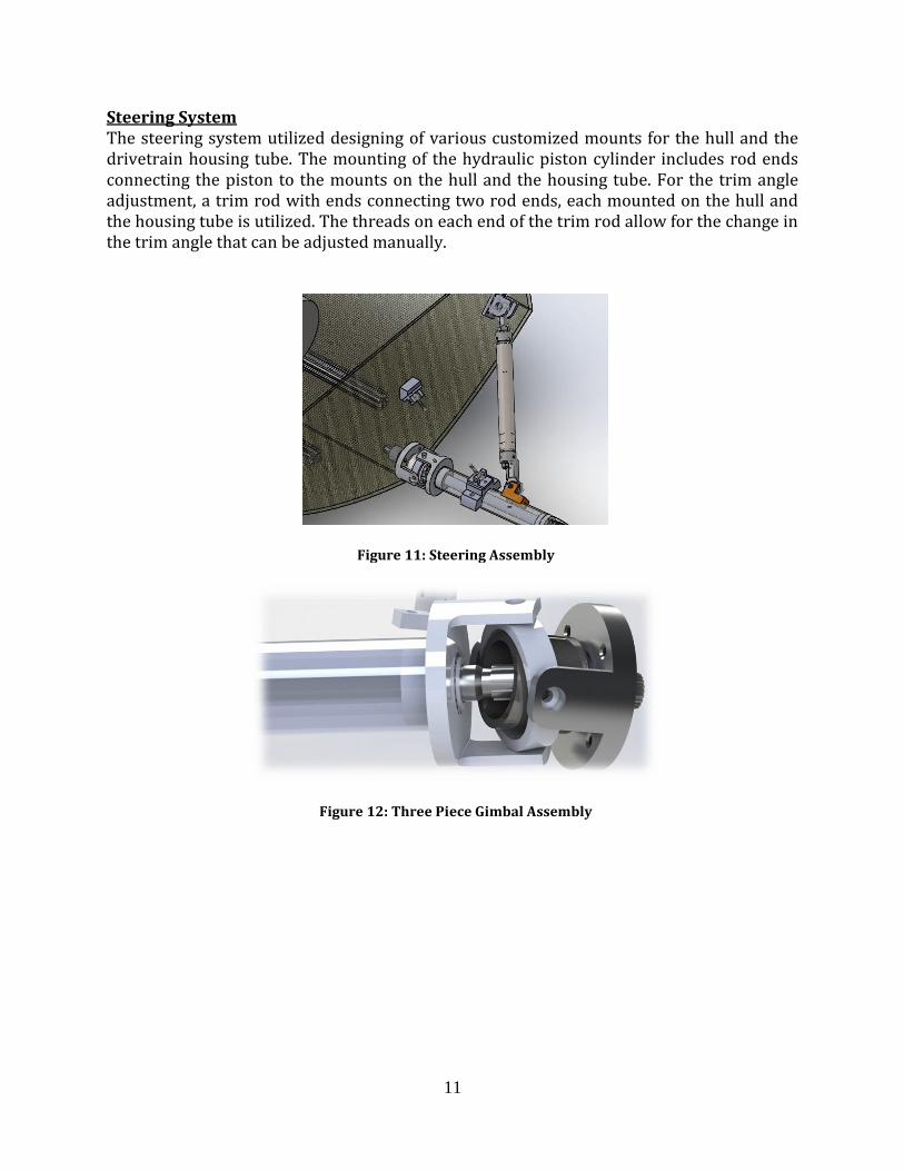
Steering System The steering system utilized designing of various customized mounts for the hull and the drivetrain housing tube. The mounting of the hydraulic piston cylinder includes rod ends connecting the piston to the mounts on the hull and the housing tube. For the trim angle adjustment, a trim rod with ends connecting two rod ends, each mounted on the hull and the housing tube is utilized. The threads on each end of the trim rod allow for the change in the trim angle that can be adjusted manually.
Figure 11: Steering Assembly
Figure 12: Three Piece Gimbal Assembly

12
DESIGN EVALUATION
HULL
We ran several tests on two carbon fiber 1/4th models at the 300 feet long towing tank at Stevens Institute under the generosity of the Davidson Laboratory. We ran tests at simulated scales of 5, 7.5, 10, 12.5, 15, 17.5, 20, and 22.5 miles per hour (mph) on both of our hulls. From this test, we gathered useful data in drag, trim, and heave. Additionally, the lab operators provided some additional tips when building our actual hull including building sharper chines and edge, correcting the center of gravity 35-40% back so the hull doesn’t hit max trim too early. From the tests, the first model hull was seen to hit the maximum trim (when the hull starts to plane) at 10-15 mph at 14 degrees while the second model hull hit the maximum trim at 10 degrees at the same speed range. Since both hulls exhibited similar drag coefficients of 2.0, the first hull design will be used for building the full scale hull (Figure 13).
Figure 13: Plots comparing the Drag Coefficients and Trim Angles for planing of two different hulls
MECHANICAL SYSTEMS
Drivetrain Once the drive shafts were modeled, a Finite Element Analysis (FEA) was done to make sure failure would not occur. The propeller shaft being the thinnest of the drive shafts had the most spots for stress concentration for failure to occur. The material of the shaft was 7075-T6 tempered aluminum. This material was chosen due to its light weight and high strength. This is also very easy to machine and very economical to use. For the fixture constraints, two bearing supports, located where the tapered roller bearing were located, were used. One face of each spline was also used as a fixed constrain which simulated the reaction force from the star of the CV joint due to the torque applied from the motors. Since at maximum continuous amperage, which is 400 A for each motor, the rated torque is 35 ft lbs, therefore, two motors produce70 ft-lbs of torque, which was used as the load for this simulation. A static test was used since it produces the greatest torque by the motor. From the simulation, it was calculated that the maximum stress was 331 ksi which led to a minimum factor of safety of 1.53. This was expected to be the area with lowest FOS.

13
Therefore, in the simulation, a finer mesh was applied to allow for more accurate results, which resulted in longer run times for the simulations.
Figure 14: Machined splines on the Propeller Shaft
The motor shaft was another area of concern due to the interface between the armatures and the shafts. Also, this shaft had a smaller diameter section among the other shafts. For this simulation, the bearing fixtures were placed according to the model. The end that sits in the armature was held as a fixed point. The torque from the motors was applied to the splines which hold the sprockets. As expected, the highest stress concentration was at the base of the splines. As can be observed form the figure, red areas occur by the base of the splines. The ring towards the outside is non-existent and only shows due to the bearing support constraints for the simulations. The highest value of stress that was found was calculated to be 99 ksi. It was much lower than the propeller shaft, due to the diameter at the spline being larger, even when the diameter at the armature is smaller than any section at the propeller shaft.
Figure 15: Motor Shaft Assembly Another major part that was thought to be more prone to failure is the spline coupler, connecting the CV joint to the U joint on the driveshaft through splines (Figure 16). Initially the part was designed to be manufactured out of 6061 Aluminum stock. However, FEA showed a maximum displacement of 0.0635408 mm on the splines. To be precautionary, reconsideration of the selected material was thought and 4140 Machinable Steel was selected to fabricated this part. Since cutting splines can only be done by either broaching or through a Wire-EDM process, it was decided to fabricate the splines using the Wire-EDM for more accuracy.

14
Figure 16: Spline Coupler
Steering System Compared to last year’s setup, this year’s steering system is mechanically more secured and is less likely to fail during different heats at the competition. The trim rod mount, that is more prone to fail, is reinforced with strong mechanical U bolts which couples it to the drivetrain housing tube, as shown in Figure 17.
Figure 17: Trim Rod Mount

15
ELECTRICAL SYSTEMS
Motor Controllers Testing of the motor controller has produced successful results that will help the team achieve high performance during competition. With the addition of a higher gear ratio and the amount of current being extracted from the batteries, the propeller will be able to run at higher RPMs without slipping. This will help the boat move at a faster speed which yet to be documented. Sensors and DAQ The sensor and DAQ systems that are being introduced this year will help us monitor multiple facets of the electrical systems on the boat which will certainly help during the endurance races. Solar Panels Our team has been trying new techniques each year to custom fabricate solar panels. The biggest challenge has been lamination of solar cells. This year, the team tries to laminate solar cells by sandwiching the cells in between two layers of EVA. Vacuum and heat are required to cure the EVA sheets; however, our attempt in doing so resulted in cracking of the cells. We are currently in the process of researching the best method to laminate cells and hope to find a solution soon.
TESTING PROCEDURES AND RESULTS
Testing of each individual sub system has been done but because of the time constraints very little testing of the entire vehicle has been done. The electrical systems have been tested on the bench and the mechanical systems have been tested in the previous year’s boat. Systems perform as expected but we will still need a bit of calibration before competition.
Discussion
The team this year set to tackle many of our previous year’s problems, mainly power consumption. Everything about this boat has been re-evaluated from the ground up. The biggest achievement is in the way we design and build our hulls. We have documented a process we hope to continue into the future as well as relationships with local companies that will benefit our club immensely. We have really come a long way in terms of the way we design, build and fabricate things since we started and we hope that this boat improves the team’s performance at the competition. We’ve learned a lot and hope to continue learning as we compete each year in the Solar Splash competition.

16
PROJECT MANAGEMENT
Team Member Organization and Responsibilities
In preparation of the 2014 Solar Splash Competition, Solar Boat Team decided to divide each of the design projects to one individual. This person is considered the project leader and is responsible for designing and manufacturing the design project. In addition, he is to create a timetable of the project and keep to the agenda. Naturally, project leaders would ask members to assist them in completing the project by handing the members a task. Members were also encouraged to come to the Solar Boat Team shop and lend a hand whenever they were available.
Project Planning and Schedule
The design process for the 2014 boat started after the 2013 competition. Weekly general body meetings, Executive board meeting and workdays have been held since September 2013 to finish the project in time. Design projects also started taking form within the month. Upon completion of the system designs, manufacturing began in the Fall semester as soon as stock material was ordered through the generous sponsors and donors at Stony Brook University and outside.
Financial and Fund Raising
For fund raising, this year’s Executive board decided to compile a sponsorship package for departments on campus at Stony Brook University and the local industries around the campus. Financial aid for this year's competition was provided by the Mechanical Engineering Department, the College of Engineering and Applied Sciences (CEAS), and the Office of Vice President of Research at Stony Brook University. Solar Boat Team also received carbon fiber donation from Hexcel Corporation and indirect assistance from Nordan Composite Technologies.
Strategy for Team Continuity and Sustainability
Currently, the team comprises of a couple of individuals from Mechanical and Electrical Engineering backgrounds. In order to expand the club, the team is always encouraging students to join. This is done by word of mouth, spreading what the club has to offer through friends, professors, and engineering departments. In addition, Solar Boat Team attends numerous on-campus and off-campus events. Participating in events allows the team to showcase their work. Aside from the size of the club, the team is doing fairly well. Though the team is limited to the few resources available in the team shop, the team can always use the resources provided by the student shop. With permission, the team also has access to some of the professors’ resources. In addition, the team is always looking for local companies who can donate some of their resources for the teams cause.

17
CONCLUSION
This year’s Stony Brook Solar Boat Team has accomplished most of the goals that were set for this year’s competition. There were some failure attempts on certain systems that the team wanted to implement on this year’s boat, however, each step we take has become a successful learning curve. The team has made great strides this year in fabrication and design philosophies. The Stony Brook Solar Boat team in its current state is has learned a great deal towards building a better boat. The team’s biggest limitation always has been aid from the university and corporations. Being a fledgling club, we do not have access to many of the sophisticated tools other teams may take for granted. Despite this, our club has stride to design and fabricate some of the most advanced systems for the Solar Splash competition. By improving every year, our club gets more recognition and with that more funding.
We also have been keeping good relations with some of the United States’ Solar Car teams. This has most certainly opened another door for sharing of knowledge as there is a good amount of information that we can obtain from their experiences in building a solar vehicle.
We hope that we are successful in the 2014 Solar Splash Competition and we come back knowing much more than we did going in. We also hope that by being successful we can continue to improve our team’s ability to create the next best thing at competition. We would like to thank those who have supported us this year and thank members who have work hard, on top of school work, to assist us in our efforts.

18
REFERENCES
1. "D1200." XS Power. Web. 3 May 2014. <http://4xspower.com/shop/d-
series/d1200/>.
2. Budynas, Richard G., J. Keith. Nisbett, and Joseph Edward. Shigley. "Clutches, Brakes,
Couplings, and Flywheels." Shigley's Mechanical Engineering Design. 9th ed. Boston:
McGraw-Hill, 2008. Print.
3. "Wisconsin Boating Safety Course." BoaterExam.com. N.p., n.d. Web. 3 May 2014.
4. "Arneson Surface Drives." Arneson Surface Drives. N.p., n.d. Web. 3 May 2014.
5. "Alltrax AXE Products Page." Alltrax Inc. Web. 3 May 2014.
<http://www.alltraxinc.com/files/Doc100-004-B_OP-AXE-Mini-Man.pdf>.

19
APPENDIX A: BATTERY DOCUMENTATION

20

21
22

23

24

25

26
APPENDIX B: FLOTATION CALCULATIONS
𝑉𝑜𝑙𝑢𝑚𝑒 𝑜𝑓 𝑡ℎ𝑒 𝑐𝑎𝑟𝑏𝑜𝑛 𝑓𝑖𝑏𝑒𝑟 ℎ𝑢𝑙𝑙: 2163.025 𝑖𝑛3
𝐷𝑒𝑛𝑠𝑖𝑡𝑦 𝑜𝑓 3 𝑙𝑎𝑦𝑒𝑟 𝑐𝑎𝑟𝑏𝑜𝑛 𝑓𝑖𝑏𝑒𝑟 𝑤𝑖𝑡ℎ 𝑟𝑒𝑠𝑖𝑛, 𝑎𝑠𝑠𝑢𝑚𝑖𝑛𝑔 𝑎 50% 𝑓𝑖𝑏𝑒𝑟 𝑡𝑜 𝑟𝑒𝑠𝑖𝑛 𝑟𝑎𝑡𝑖𝑜: 1.60𝑔𝑚
𝑐𝑐=
0.0578 𝑙𝑏/𝑖𝑛3
∴ 𝑊𝑒𝑖𝑔ℎ𝑡 𝑜𝑓 ℎ𝑢𝑙𝑙 = 125.44 𝑙𝑏𝑠.
𝐴𝑙𝑠𝑜, 𝑤𝑒𝑖𝑔ℎ𝑡 𝑜𝑓 𝑤𝑎𝑡𝑒𝑟 𝑑𝑖𝑠𝑝𝑙𝑎𝑐𝑒𝑑 𝑏𝑦 ℎ𝑢𝑙𝑙 𝑜𝑓 𝑠𝑢𝑏𝑚𝑒𝑟𝑔𝑒𝑑 𝑐𝑜𝑚𝑝𝑙𝑒𝑡𝑒𝑙𝑦 𝑖𝑛 𝑤𝑎𝑡𝑒𝑟: 2163.025
× 0.0361 = 78.085 𝑙𝑏𝑠.
Major Systems Weight Weight of water displaced
lbs. lbs.
3x Batteries 99 36.84 Drivetrain 10 5.19
Motor 20 17.68 3xSolar Panels 30 175.64
Seat 5 84.99 Hull 125.44 78.35
Total: 289.44 395.69
For a safety factor greater than 20%, we will need a buoyant force of 420 lbs., which means:
𝐹𝑜𝑎𝑚 𝑛𝑒𝑒𝑑𝑒𝑑 =420 − 78.35
62.4≅ 5.5 𝑐𝑢𝑏𝑖𝑐 𝑓𝑒𝑒𝑡 𝑜𝑓 𝑓𝑜𝑎𝑚
In order to meet the required safety factors for the competition, 5.5 cubic feet of foam or
flotation airbags will be added to the hull.

27
APPENDIX C: PROOF OF INSURANCE

28
APPENDIX D: DOCUMENTATION FOR COMMERCIAL MOTOR
CONTROLLER
Programming Instructions

29
Programming GUI

30

31
APPENDIX E: DATASHEET FOR SOLAR CHARGER

32

33
APPENDIX F: SPECIFICATIONS FOR SOLAR CELLS
KYOCERA KC 50T Solar Module
34
SHARP ND-208U2 Solar Module

35
APPENDIX G: PICTURES FROM DRAG TESTING OF PLANING HULL
PROTOTYPES
Underwater images of different hulls at different speeds

36
Side view images of different hulls at different speeds

37
APPENDIX H: SPLINE COUPLER FINITE ELEMENT ANALYSIS
Simulation of spline coupler Date: Wednesday, April 02, 2014 Designer: Solidworks Study name: Study 1 Analysis type: Static
Description No Data

38
Assumptions
Model Information
Model name: spline coupler
Current Configuration: Default
Solid Bodies
Document Name and Reference
Treated As Volumetric Properties Document Path/Date
Modified
Fillet1
Solid Body
Mass:0.0909491 kg Volume:3.36848e-005 m^3
Density:2700 kg/m^3 Weight:0.891301 N
C:\Users\solarboat\Google Drive\Drivetrain\Internal
Drivetrain\spline coupler.SLDPRT
Mar 29 15:38:39 2014

39
Study Properties Study name Study 1
Analysis type Static
Mesh type Solid Mesh
Thermal Effect: On
Thermal option Include temperature loads
Zero strain temperature 298 Kelvin
Include fluid pressure effects from SolidWorks Flow Simulation
Off
Solver type FFEPlus
Inplane Effect: Off
Soft Spring: Off
Inertial Relief: Off
Incompatible bonding options Automatic
Large displacement Off
Compute free body forces On
Friction Off
Use Adaptive Method: Off
Result folder SolidWorks document (C:\Users\solarboat\Google Drive\Drivetrain\Internal Drivetrain)
Units Unit system: SI (MKS)
Length/Displacement mm
Temperature Kelvin
Angular velocity Rad/sec
Pressure/Stress N/m^2

40
Material Properties
Model Reference Properties Components
Name: 6061 Alloy Model type: Linear Elastic Isotropic
Default failure criterion:
Max von Mises Stress
Yield strength: 5.51485e+007 N/m^2 Tensile strength: 1.24084e+008 N/m^2 Elastic modulus: 6.9e+010 N/m^2
Poisson's ratio: 0.33 Mass density: 2700 kg/m^3
Shear modulus: 2.6e+010 N/m^2 Thermal expansion
coefficient: 2.4e-005 /Kelvin
SolidBody 1(Fillet1)(spline coupler)
Curve Data:N/A
Loads and Fixtures
Fixture name Fixture Image Fixture Details
Fixed-1
Entities: 1 face(s) Type: Fixed Geometry
Resultant Forces Components X Y Z Resultant
Reaction force(N) -75.4978 57.2902 0.0620964 94.7739
Reaction Moment(N·m) 0 0 0 0
Load name Load Image Load Details
Torque-1
Entities: 21 face(s) Reference: Axis1
Type: Apply torque Value: 900 lbf·in

41
Mesh Information Mesh type Solid Mesh
Mesher Used: Standard mesh
Automatic Transition: Off
Include Mesh Auto Loops: Off
Jacobian points 4 Points
Element Size 0.114473 in
Tolerance 0.00572365 in
Mesh Quality High
Mesh Information - Details
Total Nodes 42100
Total Elements 26595
Maximum Aspect Ratio 38.321
% of elements with Aspect Ratio < 3 65.6
% of elements with Aspect Ratio > 10 11.6
% of distorted elements(Jacobian) 0
Time to complete mesh(hh;mm;ss): 00:00:07
Computer name: SOLARBOAT1
42
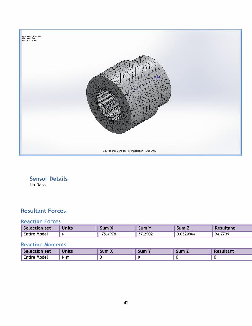
Sensor Details No Data
Resultant Forces
Reaction Forces
Selection set Units Sum X Sum Y Sum Z Resultant
Entire Model N -75.4978 57.2902 0.0620964 94.7739
Reaction Moments
Selection set Units Sum X Sum Y Sum Z Resultant
Entire Model N·m 0 0 0 0

43
Study Results
Name Type Min Max
Stress1 VON: von Mises Stress 332912 N/m^2 Node: 39735
4.77474e+008 N/m^2 Node: 41814
spline coupler-Study 1-Stress-Stress1
Name Type Min Max
Displacement1 URES: Resultant Displacement 0 mm Node: 1
0.0635408 mm Node: 39742
44
spline coupler-Study 1-Displacement-Displacement1
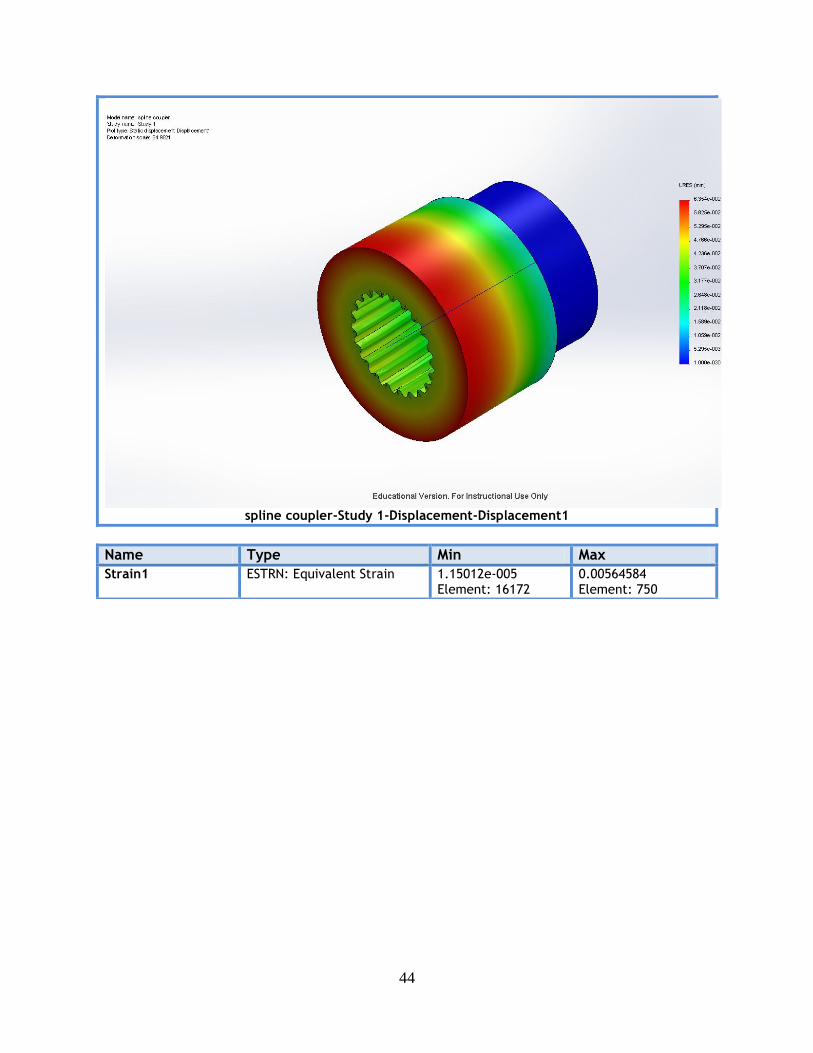
Name Type Min Max
Strain1 ESTRN: Equivalent Strain 1.15012e-005 Element: 16172
0.00564584 Element: 750

45
spline coupler-Study 1-Strain-Strain1

46
APPENDIX I: FINITE ELEMENT ANALYSIS (PROPELLER SHAFT)
Simulation of prop shaft Date: Thursday, May 09, 2013 Designer: Solidworks Study name: Study 2 Analysis type: Static
Description No Data

47
Assumptions
Model Information
Model name: prop shaft
Current Configuration: Default
Solid Bodies
Document Name and Reference
Treated As Volumetric Properties Document Path/Date
Modified
CirPattern1
Solid Body
Mass:0.857437 kg Volume:0.000305138 m^3
Density:2810 kg/m^3 Weight:8.40288 N
C:\Users\Vinny Calandrino\Google Drive\Solar Boat
2012\Drive Train\sprint drive\prop shaft.SLDPRT May 09 19:13:25 2013
48
Study Properties Study name Study 2
Analysis type Static
Mesh type Solid Mesh
Thermal Effect: On
Thermal option Include temperature loads
Zero strain temperature 298 Kelvin
Include fluid pressure effects from SolidWorks Flow Simulation
Off
Solver type FFEPlus
Inplane Effect: Off
Soft Spring: Off
Inertial Relief: Off
Incompatible bonding options Automatic
Large displacement Off
Compute free body forces On
Friction Off
Use Adaptive Method: Off
Result folder SolidWorks document (C:\Users\Vinny Calandrino\Google Drive\Solar Boat 2012\Drive Train\sprint drive)
Units Unit system: SI (MKS)
Length/Displacement mm
Temperature Kelvin
Angular velocity Rad/sec
Pressure/Stress N/m^2

49
Material Properties
Model Reference Properties Components
Name: 7075-T6 (SN) Model type: Linear Elastic Isotropic
Default failure criterion:
Max von Mises Stress
Yield strength: 5.05e+008 N/m^2 Tensile strength: 5.7e+008 N/m^2 Elastic modulus: 7.2e+010 N/m^2
Poisson's ratio: 0.33 Mass density: 2810 kg/m^3
Shear modulus: 2.69e+010 N/m^2 Thermal expansion
coefficient: 2.36e-005 /Kelvin
SolidBody 1(CirPattern1)(prop shaft)
Curve Data:N/A

50
Loads and Fixtures
Fixture name Fixture Image Fixture Details
Fixed-1
Entities: 6 face(s) Type: Fixed Geometry
Resultant Forces Components X Y Z Resultant
Reaction force(N) 95.1186 0.970887 -0.408834 95.1244
Reaction Moment(N-m) 0 0 0 0
Load name Load Image Load Details
Torque-1
Entities: 2 face(s) Reference: Axis2
Type: Apply torque Value: 900 lbf-in
Image-3
Image-4

51
Connector Definitions Pin/Bolt/Bearing Connector
Model Reference Connector Details Strength Details
Bearing Support-1
Entities: 1 face(s) Type: Bearing
No Data
Connector Forces Type X-Component Y-Component Z-Component Resultant
Axial Force (N) -0 0 0 0
Shear Force (N) 0 0 0 0
Bending moment (N-m) 0 0 0 0
Bearing Support-2
Entities: 1 face(s) Type: Bearing
No Data
Connector Forces Type X-Component Y-Component Z-Component Resultant
Axial Force (N) -0 0 0 0
Shear Force (N) 0 0 0 0
Bending moment (N-m) 0 0 0 0
Contact Information No Data

52
Mesh Information Mesh type Solid Mesh
Mesher Used: Standard mesh
Automatic Transition: Off
Include Mesh Auto Loops: Off
Jacobian points 16 Points
Element Size 0.18654 in
Tolerance 0.00932699 in
Mesh Quality High
Mesh Information - Details
Total Nodes 58024
Total Elements 36440
Maximum Aspect Ratio 34.188
% of elements with Aspect Ratio < 3 92.5
% of elements with Aspect Ratio > 10 1.13
% of distorted elements(Jacobian) 0
Time to complete mesh(hh;mm;ss): 00:00:15
Computer name: VINNYCALANDRINO

53
Mesh Control Information:
Mesh Control Name Mesh Control Image Mesh Control Details
Control-1
Entities: 26 face(s) Units: in Size: 0.077189
Ratio: 1.5

54
Control-2
Entities: 38 face(s) Units: in Size: 0.0828512
Ratio: 1.5
Sensor Details
Sensor name Location Sensor Details
Mass1
Value : 1.82840485 lb Entities : Result :Stress Component :VON: von Mises Stress Criterion :Model Max Step Criterion : Across all Steps Step No.:1 Alert Value: NA
Resultant Forces
Reaction Forces
Selection set Units Sum X Sum Y Sum Z Resultant
Entire Model N 95.1186 0.970887 -0.408834 95.1244
Reaction Moments
Selection set Units Sum X Sum Y Sum Z Resultant
Entire Model N-m 0 0 0 0
Beams No Data

55
Study Results
Name Type Min Max
Stress1 VON: von Mises Stress 2416.98 N/m^2 Node: 8237
3.31068e+008 N/m^2 Node: 38319
prop shaft-Study 2-Stress-Stress1
Name Type Min Max
Displacement1 URES: Resultant Displacement 0 mm Node: 3082
1.36032 mm Node: 53630

56
prop shaft-Study 2-Displacement-Displacement1
Name Type Min Max
Strain1 ESTRN: Equivalent Strain 3.66842e-008 Element: 10780
0.00334271 Element: 15703

57
prop shaft-Study 2-Strain-Strain1
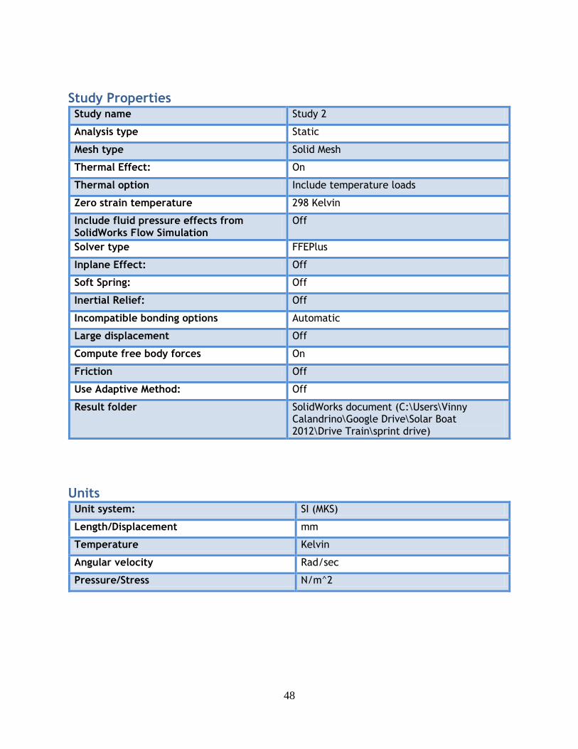
Name Type Min Max
Factor of Safety2 Max von Mises Stress 1.52536 Node: 38319
208938 Node: 8237
58
prop shaft-Study 2-Factor of Safety-Factor of Safety2
Image-2
Image-1

59
Image-5

60
Image-6

61
Image-7