bm40, bm40pb, bm40ie industrial amplifier · zero drift k / 10 k < 0.2 full-scale drift k / 10 k...
TRANSCRIPT
B4641-1.0 en HBM: public
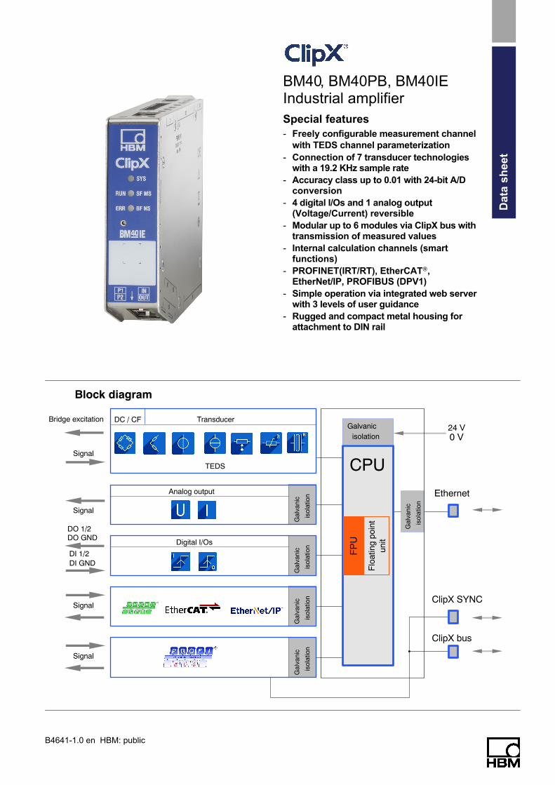
Block diagram
Gal
vani
c
isol
atio
n
Gal
vani
c
isol
atio
n
Gal
vani
c
isol
atio
n
Gal
vani
c
isol
atio
n
TEDS
TransducerDC / CF
Signal
Signal
Signal
DO 1/2DO GND
DI 1/2DI GND
Signal
Bridge excitation
Analog output
Digital I/Os
FP
U
Flo
atin
g po
int
unit
Galvanicisolation
Gal
vani
c
isol
atio
n
Ethernet
ClipX SYNC
24 V0 V
ClipX bus
CPU
BM40, BM40PB, BM40IEIndustrial amplifier
Special features
- Freely configurable measurement channel
with TEDS channel parameterization
- Connection of 7 transducer technologieswith a 19.2 KHz sample rate
- Accuracy class up to 0.01 with 24-bit A/Dconversion
- 4 digital I/Os and 1 analog output(Voltage/Current) reversible
- Modular up to 6 modules via ClipX bus withtransmission of measured values
- Internal calculation channels (smartfunctions)
- PROFINET(IRT/RT), EtherCAT,EtherNet/IP, PROFIBUS (DPV1)
- Simple operation via integrated web serverwith 3 levels of user guidance
- Rugged and compact metal housing forattachment to DIN rail
Data
sh
eet

B4641-1.0 en HBM: publicHBM 2
Specifications for ClipX
General specifications BM40, BM40PB, BM40IE
Measurement input Number 1, galvanically isolated to supply
Transducer technologies Strain gage full and half bridge, piezoresistive sensors(voltage-fed), potentiometric transducers, resistance
thermometers (PT100), voltage (�10V), electriccurrent (�20mA)
A/D conversion bit 24 delta-sigma converter
Sample rate S/s 19,200
Signal bandwidth Hz Direct voltage bridge excitation (DC): 3,500 Hz whenfilter off
Carrier frequency sensor excitation (CF): 200 Hz
Active low-pass filter Hz Bessel or Butterworth
DC: 0.02 … 3,000; filter OFF
CF: 0.02 … 200
Transducer identification
TEDS module distance, max. (IEEE 1415.1) m 100
Supply voltage range VDC 10 … 30 (nominal (rated) voltage 24 V)
Supply voltage interruption (based on PLC standard DIN EN 61131-2)
24 V (- 10 %)
12 V (- 10 %)
ms
ms
10
1
Power consumption at 24 V supply voltage, max. W 5
Galvanic isolation V 60Between voltage supply, sensor input, ClipX bus, analogoutput, all digital I/Os, and fieldbuses except PROFIBUS
Fuses
Automatic current limiter
Short-circuit resistance
None
For all input and output signals
Input/output signals, synchronization and fieldbus areshort-circuit proof and coding elements can be used to
safeguard the connector plugs, so they are nottransposed.
Ethernet (data link) 10Base‐T / 100Base‐TX
Protocol/addressing TCP/IP (direct IP address or DHCP)
Plug connection RJ45, 8-pin
Cable type Standard LAN, CAT5, SFTP
Max. cable length to device m 100
ClipX bus (data transfer)
Number of devices, max. 6
Data transfer 1 data value (measured value, calculated value, etc.) withstatus
Transmission speed kHz 1, with automatic synchronization
Protocol / addressing RS485, node 1 … 6
Cabling Wires, twisted in pairs and shielded
Distance between 2 modules, max. cm 30

B4641-1.0 en HBM: public 3 HBM
Specifications for ClipX (continued)
Real time calculation in device
Calculation channels Number 6
Update rate
Functions
ms 1
Algebra (+ - * /), 2x2.. 6x6 matrix compensation, logicfunctions (AND, OR, …)
Peak-value memory
Number
Reference level
Response time, typical �s
3 (min., max., peak-to-peak)
All measurement signals, all calculation channels, datafrom ClipX bus, fieldbus and Ethernet, Analog output
52
Limit value switch
Number
Reference level
Function
Response tim, typical �s
4
All measurement signals, all calculation channels, datafrom ClipX bus, fieldbus and Ethernet, Analog output
Exceeding or falling below a levelInside / outside a tolerance band
300
Digital inputs
Number
Function
Response time, typical ms
2
Zero, tare, reset limit value, digital output,parameter set selection (bit-coded), flags from
calculation channels
1
Digital outputs
Number
Function
Response time, typical ms
2, designed as high‐side switches
Limit value, digital input, measured value/systemstatus, fieldbus flag, current parameter set number
(bit-coded), calculation channel flags and Ethernet APIflags
1
Parameter sets
Number
Device “cloning”
10, sensor settings, measurement acquisition incl.calculation channels, limit values, digital input/output
settings, analog output settings
All the device settings can be saved in full to a PC as abackup and reloaded, either with or without Ethernet
and fieldbus settings
Nominal (rated) temperature range C 0 … 50
Operating temperature range (no condensationallowed/module not immune to water condensation) C -20 … + 60
Storage temperature range C -25 … +75
Rel. humidity % 5 … 95 (non-condensing)
Class (height up to 2,000 m, degree of contamination 2) III (as per EN 61140)
Equipment protection level IP20 (as per EN 60529)
Mechanical tests (Device switched of, in compliancewith EN61131-2 PLC hardware standard)
Oscillation (90 min in each direction)
Impact (3 times in each direction)
g
g
2 (20 m/s2); 8,4 … 200 Hz (constant acceleration);5…8,4 Hz (constant amplitude 14 mm);
35 (350 m/s2); sinusoidal; impact duration 6 ms
EMC requirements Compliance with Class B according to EN 55011(emissions) Group 1.
For ESD and surge, compliance with criterion Baccording to EN 61326-1) (immunity)
Proof of quality Manufacturer’s certificate 2.1 as per EN 10204 and theHBM factory calibration certificate can be downloaded
from https://www.hbm.com/ClipX

B4641-1.0 en HBM: publicHBM 4
Specifications for ClipX (continued)
Long-term stability All devices are pre-aged in an oven run to improvelong-term stability.
Dimensions, (H x W x D), including DIN rail mountingmaterial mm 100 x 25 x 118
Weight approx. g 360
Strain gage full bridge BM40, BM40PB, BM40IE
Accuracy class 0.01
Transducers that can be connected Strain gage full bridges
Transducer impedance � 80 … 5,000
Measurement ranges (at 5 V bridge excitation) mV/V 2.5 or 5, reversible
Bridge excitation voltage V 5 (� 10 %), direct voltage (DC) or carrier frequency(CTF) 1200 Hz reversible
Signal bandwidth (-3 dB) Hz DC: 0 … 3,500
CF: 0 … 200
Permissible cable length between ClipX and transducer m < 100
Transducer identification TEDS, IEEE 1415.1; either 1-wire® technology withseparate TEDS chip or HBM 0-wire technology with
TEDS chip in the sense leads of the sensor
Noise (peak‐to‐peak)at 25 �C, 5 V bridge excitation(DC), 350 Ohm full bridge
with 1 Hz Bessel filter
with 10 Hz Bessel filter
with 100 Hz Bessel filter
with 1 kHz Bessel filter
�V/V
�V/V
�V/V
�V/V
0.04
0.12
0.4
1.2
Noise (peak‐to‐peak)at 25 �C, 5 V bridge excitation(CF), 350 Ohm full bridge
with 1 Hz Bessel filter
with 10 Hz Bessel filter
with 100 Hz Bessel filter
with 200 Hz Bessel filter
�V/V
�V/V
�V/V
�V/V
0.05
0.16
0.5
0.8
Non-linearity % 0.005 of full scale value
Zero drift (bridge excitation 5 V) % / 10 K 0.01 of full scale value
Full-scale drift (bridge excitation 5 V) % / 10 K 0.01 of measured value
Strain gage half bridge BM40, BM40PB, BM40IE
Accuracy class 0.01
Transducers that can be connected Strain gage half bridges
Transducer impedance � 80 … 5,000
Measurement ranges (at 5 V bridge excitation) mV/V 2.5 or 5; reversible
Bridge excitation voltage V 5 (� 10 %), direct voltage (DC) or carrier frequency(CF) 1200 Hz reversible
Signal bandwidth (-3 dB) Hz DC: 0 … 3,500
CF: 0 … 200
Permissible cable length between ClipX and transducer m < 100
Transducer identification TEDS, IEEE 1415.1; either 1-wire technology withseparate TEDS chip or HBM 0-wire technology with
TEDS chip in the sense leads of the sensor
Noise (peak‐to‐peak)at 25 �C, 5 V bridge excitation(DC), 350 Ohm half bridge
with 1 Hz Bessel filter
with 10 Hz Bessel filter
with 100 Hz Bessel filter
with 1 kHz Bessel filter
�V/V
�V/V
�V/V
�V/V
0.08
0.24
0.8
2.4

B4641-1.0 en HBM: public 5 HBM
Specifications for ClipX (continued)
Noise (peak‐to‐peak) at 25 �C, 5 V bridge excitation(CF), 350 Ohm half bridge
with 1 Hz Bessel filter
with 10 Hz Bessel filter
with 100 Hz Bessel filter
with 200 Hz Bessel filter
�V/V
�V/V
�V/V
�V/V
0.1
0.32
1
1.6
Non-linearity % 0.05 of full scale value
Zero drift (bridge excitation 5 V) % / 10 K 0.1 of full scale value
Full-scale drift (bridge excitation 5 V) % / 10 K 0.1 of measured value
Resistive full bridge BM40, BM40PB, BM40IE
Accuracy class 0.01
Transducers that can be connected Resistive full bridge, voltage-fed
Transducer impedance � 80 … 5,000
Measurement ranges (at 5 V bridge excitation) mV/V 100 or 800, reversible
Bridge excitation voltage V 5 (� 10 %), direct voltage (DC)
Signal bandwidth (-3 dB) Hz DC: 0 … 3,500
Permissible cable length between ClipX and transducer m < 100
Transducer identification TEDS, IEEE 1415.1; either 1-wire technology withseparate TEDS chip or HBM 0-wire technology with
TEDS chip in the sense leads of the sensor
Noise (peak‐to‐peak) at 25 �C, at 100 mV/V, 5 V bridgeexcitation (DC), 350 Ohm full bridge
with 1 Hz Bessel filter
with 10 Hz Bessel filter
with 100 Hz Bessel filter
with 1 kHz Bessel filter
�V/V
�V/V
�V/V
�V/V
0.2
0.4
1.5
5
Noise (peak‐to‐peak)at 25 �C, at 800 mV/V, 5 V bridgeexcitation (DC), 350 Ohm full bridge
with 1 Hz Bessel filter
with 10 Hz Bessel filter
with 100 Hz Bessel filter
with 1 kHz Bessel filter
�V/V
�V/V
�V/V
�V/V
0.6
1.2
4.5
15
Non-linearity % 0.05 of full scale value
Zero drift (bridge excitation 5 V) % / 10 K 0.01 of full scale value
Full-scale drift (bridge excitation 5 V) % / 10 K 0.01 of measured value
Potentiometric transducers / potentiometers BM40, BM40PB, BM40IE
Accuracy class 0.1
Transducers that can be connected Potentiometric transducers
Transducer impedance � 80 … 5,000
Measurement ranges (at 5 V bridge excitation) mV/V 500, corresponding to 0 … 100 %
Bridge excitation voltage V 5 (� 10 %), direct voltage (DC)
Signal bandwidth (-3 dB) Hz DC: 0 … 3,500
Permissible cable length between ClipX and transducer m < 100
Transducer identification TEDS, IEEE 1415.1; 1-wire technology with separateTEDS chip
Noise (peak-to-peak) at 25 �C , Potentiometric transducer, 5 V bridge excitation (DC), 10k Poti, middleposition
with 1 Hz Bessel filter
with 10 Hz Bessel filter
with 100 Hz Bessel filter
with 1 kHz Bessel filter
%
%
%
%
0.00008
0.00025
0.001
0.003
Non-linearity % 0.05 of full scale value
Zero drift (bridge excitation 5 V) % / 10 K 0.1 of full scale value
Full-scale drift (bridge excitation 5 V) % / 10 K 0.1 of measured value
B4641-1.0 en HBM: publicHBM 6
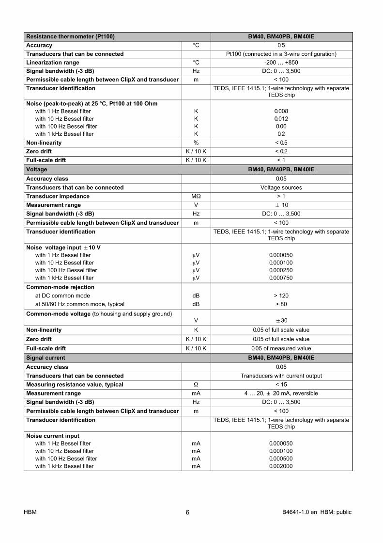
Resistance thermometer (Pt100) BM40, BM40PB, BM40IE
Accuracy C 0.5
Transducers that can be connected Pt100 (connected in a 3‐wire configuration)
Linearization range C -200 … +850
Signal bandwidth (-3 dB) Hz DC: 0 … 3,500
Permissible cable length between ClipX and transducer m < 100
Transducer identification TEDS, IEEE 1415.1; 1-wire technology with separateTEDS chip
Noise (peak-to-peak) at 25 �C, Pt100 at 100 Ohm
with 1 Hz Bessel filter
with 10 Hz Bessel filter
with 100 Hz Bessel filter
with 1 kHz Bessel filter
K
K
K
K
0.008
0.012
0.06
0.2
Non-linearity % < 0.5
Zero drift K / 10 K < 0.2
Full-scale drift K / 10 K < 1
Voltage BM40, BM40PB, BM40IE
Accuracy class 0.05
Transducers that can be connected Voltage sources
Transducer impedance M� > 1
Measurement range V � 10
Signal bandwidth (-3 dB) Hz DC: 0 … 3,500
Permissible cable length between ClipX and transducer m < 100
Transducer identification TEDS, IEEE 1415.1; 1-wire technology with separateTEDS chip
Noise voltage input �10 V
with 1 Hz Bessel filter
with 10 Hz Bessel filter
with 100 Hz Bessel filter
with 1 kHz Bessel filter
�V
�V
�V
�V
0.000�050
0.000�100
0.000�250
0.000�750
Common-mode rejection
at DC common mode
at 50/60 Hz common mode, typical
dB
dB
> 120
> 80
Common-mode voltage (to housing and supply ground)V �30
Non-linearity K 0.05 of full scale value
Zero drift K / 10 K 0.05 of full scale value
Full-scale drift K / 10 K 0.05 of measured value
Signal current BM40, BM40PB, BM40IE
Accuracy class 0.05
Transducers that can be connected Transducers with current output
Measuring resistance value, typical � < 15
Measurement range mA 4 … 20, � 20 mA, reversible
Signal bandwidth (-3 dB) Hz DC: 0 … 3,500
Permissible cable length between ClipX and transducer m < 100
Transducer identification TEDS, IEEE 1415.1; 1-wire technology with separateTEDS chip
Noise current input
with 1 Hz Bessel filter
with 10 Hz Bessel filter
with 100 Hz Bessel filter
with 1 kHz Bessel filter
mA
mA
mA
mA
0.000�050
0.000�100
0.000�500
0.002�000

B4641-1.0 en HBM: public 7 HBM
Specifications for ClipX (continued)
Common-mode rejection
at DC common mode
at 50/60 Hz common mode, typical
dB
dB
> 120
> 80
Common-mode voltage (to housing and supplyground) V �30
Non-linearity % 0.05 of full scale value
Zero drift K / 10 K 0.05 of full scale value
Full-scale drift K / 10 K 0.05 of measured value

B4641-1.0 en HBM: publicHBM 8
Specifications for ClipX (continued)
Input / Output
Analog output BM40, BM40PB, BM40IE
Voltage output
Accuracy class 0.1
Number 1
Signal sources All measurement signals, all calculation channels, datafrom ClipX bus, fieldbus and Ethernet
Output signal V � 10; reversible, short-circuit proof
D/A converter resolution bit 16
Output rate, max. kHz 19.2
Cut-off frequency (-3 dB) kHz 2
Output resistance � < 320
Permissible input impedance 10 k� II 20 nF
Permissible cable length, max. m 100
Noise (peak-to-peak) mV < 10
Non-linearity (INL) Integral Non Linearity LSB < �27
Zero drift rel. to full scale mV / 10 K < 2
Full-scale drift rel. to output value mV / 10 K < 2
Current output
Accuracy class 0.1
Number 1
Signal sources All measurement signals, all calculation channels, datafrom ClipX bus, fieldbus and Ethernet
Output signal mA 4 … 20 mA, reversible, short-circuit proof
D/A converter resolution bit 16
Output rate, max. kHz 19.2
Cut-off frequency (-3 dB) kHz 2
Permitted burden � < 400
Permissible cable length, max. m 100
Noise (peak-to-peak) �A < 60
Non-linearity (INL) Integral Non Linearity LSB < �27
Zero drift rel. to full scale �A / 10 K < 5
Full-scale drift rel. to output value �A / 10 K < 10
Digital inputs BM40, BM40PB, BM40IE
Number 2
Functions Zero, tare, reset limit value, digital output, parameterset selection (bit-coded), flags from calculation
channels
Switching time ms < 1
Input signal range
Maximum permitted input signal range
Low state input
High state input
V
V
V
V
0 … 30
30
0 … 5 (or open)
10 … 30
Input resistance (nominal) k� 2.4
Cable length, max. m 100
Cable type (required in the event of interference) shielded

B4641-1.0 en HBM: public 9 HBM
Specifications for ClipX (continued)
Digital outputs BM40, BM40PB, BM40IE
Number 2, short-circuit proof
Functions Limit value, digital input, measured value/systemstatus, fieldbus flag, current parameter set number
(bit-coded), calculation channel flags
Switching time ms < 1
Input voltage V Operating voltage
Output current per output, max. mA 200
Output current (outputs total), max. mA 400
Output impedance � < 1
Start-up characteristics Low until the ClipX transmits the required level
Fieldbuses
PROFIBUS BM40PB
Bit rate kBit/s 9.6 … 12,000 auto‐detect
Node address 3 - 126adjustable via the web user interface
Factory setting: 126
Configuration data, max. bytes 244
Logical slots 30
Cyclic output data (master -> ClipX), max. bytes 160
Cyclic input data (ClipX -> master), max. bytes 160
Cycle time (slave interval), min. ms 0.6
Acyclic data protocol DP V1 Class 1 and Class 2A list with the data objects can be downloaded via the
web user interface
Acyclic data, max. bytes 240
Male connector 9-pin DSub; galvanically isolated from supply andmeasurement ground
PROFIBUS Ident No. 0x1015
Industrial Ethernet IE BM40IE
In the BM40IE device, the operator can toggle between fieldbus types using the ClipX Web Server
EtherCAT1)
Type EtherCAT complex slave
Cable type Standard CAT-5, shielded
Cable length, max. m 100
Connector socket 2x RJ45 (IN / OUT)
Input data, max. bytes 166
Output data, max. bytes 44
Online device description CAN over EtherCAT Object Dictionary (ESI file notrequired)
Offline device description ESI file stored in the device
Data rate, max. kHz 4
Distributed clocks
Minimum cycle time �s Supported, 32 bits
250
1) EtherCAT is a registered brand and patented technology, licensed by Beckhoff Automation GmbH, Germany

B4641-1.0 en HBM: publicHBM 10
Specifications for ClipX (continued)
EtherNet/IP
Type Communication adapter
Cable type Standard CAT-5, shielded
Cable length, max. m 100
Connector socket 2 x RJ45
Input data, max. bytes 166
Output data, max. bytes 44
IO connection types Exclusive owner, Listen only, Input only
IO connection trigger types Cyclic, minimum 1 ms1),Application triggered, minimum 1 ms1),
Change of state, minimum 1 ms1)
Explicit messages connections 10
Implicit messages connections 5
Unconnected Message Manager (UCMM) 10
Configuration control STATIC, BOOTP, DHCP
Bit rates Mbit/s 10, 100
Duplex modes Half, full, auto negotiation
Data transport layer Ethernet II, IEEE 802.3
Address collision detection supported
Device level ring supported
Integrated switch supported
Reset services Type 0, type 1
Quick connect not supported
Tags not supported
CIP Sync not supported
1) Depends on the number of connections and the IO quantities

B4641-1.0 en HBM: public 11 HBM
Specifications for ClipX (continued)
PROFINET
Cable type Standard CAT-5, shielded
Cable length, max. m 100
Connector socket 2x RJ45 (port1 / port 2)
Real time classes 1 (“RT”) / 3 (“IRT”)
Device access point “slow”
Cycle time Class 1
Cycle time Class 3
Slots / max. number of modules
Input data, max.
Output data, max.
ms
ms
-
bytes
bytes
1 / 2 / 4
1 / 2 / 4
30
180
100
Device access point “fast”
Cycle time Class 1
Cycle time Class 3
Slots / max. number of modules
Input data, max.
Output data, max.
ms
ms
bytes
bytes
1 / 2 / 4
0.25 / 0.5 / 1 / 2 / 4
6
60
40
Supported protocols RTC (Real Time Cyclic)
Class 1, unsynchronized
Class 3, synchronized
RTA - Real Time Acyclic
DCP - Discovery and Configuration
DCE/RPC - Distributed Computing
Environment - Connectionless Remote
Procedure Calls
LLDP - Link Layer Discovery Protocol
PTCP - Precision Transparent Clock Protocol
SNMP - Simple Network Management Protocol
Media redundancy MRP client
Identification & Maintenance I&M0 … I&M3 read and write

B4641-1.0 en HBM: publicHBM 12
Specifications for ClipX (continued)
Signal transit times (ms)
Group 1: Measured values
1)
2)
2)
min. 52 �s260 �s
1) Filter off: 0 s; Bessel filter: 0.43/fg ; Butterworth filter: 0.66/fg ; The result is time in seconds
for an output signal of 50% of the full scale value with a jump at the input
.
2) These signals can also use other sources. The phase delays of the source signals must then be added.
3) If the analog output is to transmit a value from this group, you must add an additional 52 μs. If you are using a source from a
different group, you must add the phase delay of the source signal to the 52 μs.
A/D converter (ADC)
Filter
A/D unfilteredADC filteredField value (el. value)Gross valueNet valueMinimumMaximumPeak-to-peak
2)
2)
Limit valueswitches
Analog output3)
Fig.1: Minimum transit times for group 1: 52 μs plus A/D converter conversion time
Group 2: Flags, digital I/O, calculated values, ClipX bus
1 ms
Digital flags
(I/O flags) 1) 2)3)
1) The changes in digital flags are analyzed in the following order: Zero, tare, clear zero balance, clear tare balance; reset
limit value switches; reset peak values; hold held values; clear held values.
2) The digital outputs have an additional response time of max. 0.25 ms.
3) Asynchronous transfer of the values on the ClipX bus is complete after max. 1 ms, i.e. on the next cycle.
Flags and valuesfrom the fieldbus
Digitalinputs
Calculatedchannels
Digitaloutputs
Start ClipX bustransmission
Fig.2: Maximum transit time for group 2: 1 ms

B4641-1.0 en HBM: public 13 HBM
Specifications for ClipX (continued)
Group 3: Data from fieldbus master to ClipX
approx. 250 �s250 �s1)
1 ms
1)
0.25 1 ms
Polling rateEtherCAT/PROFINET
Polling rateEtherNet/IP/PROFIBUS
ClipXfieldbus
controller
Fieldbus framerate period
At 4 kHz frame rate
Fig.3: Transit time for group 3
Group 4: Data from ClipX to fieldbus master
250 �s1)
1 ms
1)
approx. 250 �s 0.25 1 ms
Fieldbus framerate period
ClipXfieldbus
controllerUpdate rateEtherNet/IP/PROFIBUS
Update rateEtherCAT/PROFINET
At 4 kHz frame rate
Fig.4: Transit time for group 4

B4641-1.0 en HBM: publicHBM 14
Specifications for ClipX (continued)
ClipX variants
BM40IEBM40 BM40PB
Profibus device Industrial Ethernet deviceAnalog device
Function overview
Ethernet connection
Bridge excitation, digital I/O
Transducer connection
1
2
3
4
P1 IN5
6
8
LED system status
LED fieldbus status 2
9
HBM calibration mark
Function push button
10
7
LED fieldbus status 1Analog output
Customer-specific label 11
12
RealTime, Ethernet/IP;
PROFINET, EtherCatP2 OUT
4
32
1
5
6
7
8
11
10
9
12
2x RJ or one 9-pin D‐Sub
female connector

B4641-1.0 en HBM: public 15 HBM
Specifications for ClipX (continued)
PIN assignment
32
1
2
3
1
Analog output, 3-pin (Phoenix MC1.5/12-G-3.5)
Supply, digital I/O, ClipX bus, 12-pin (Phoenix MC1.5/12-G-3.5)
Transducer, 13-pin (Phoenix MC1.5/13-G-3.5)
U IN
I IN
Outer shield
TEDS
4 measurement signal -
1 measurement signal +
3' sense lead +
2 bridge excitation voltage -
2' sense lead -
3 bridge excitation voltage +
Pt100
4
4
Ethernet (communication); RJ45
Standard assignment
Plug terminals :
An alternative to plug terminals:
Screw terminals, obtained directly from Phoenix
S
AICable shield
0 V
24 V
DO2
DI1
CxB
X
0I
DI2
DO1
CxA
Sync
AO
AO
ClipX bus A (RS485+)
ClipX bus B (RS485-)
ClipX bus GND
Digital In GND
Digital In 2
Digital In 1
Digital Out 2
Power supply
Power supply / Digital Out GND
Digital Out 1
Analog Out
Analog Out Gnd
B4641-1.0 en HBM: publicHBM 16
Specifications for ClipX (continued)
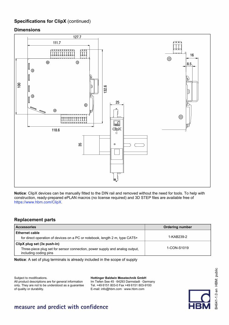
Dimensions
111.7
132.6
118.6
100
25
35
127.7
16
8.5
Notice: ClipX devices can be manually fitted to the DIN rail and removed without the need for tools. To help withconstruction, ready-prepared ePLAN macros (no license required) and 3D STEP files are available free ofhttps://www.hbm.com/ClipX.
Replacement parts
Accessories Ordering number
Ethernet cable
for direct operation of devices on a PC or notebook, length 2 m, type CAT5+ 1-KAB239-2
ClipX plug set (3x push‐in)
Three-piece plug set for sensor connection, power supply and analog output,including coding pins
1-CON-S1019
Notice: A set of plug terminals is already included in the scope of supply
measure and predict with confidence
Hottinger Baldwin Messtechnik GmbH
Im Tiefen See 45 64293 Darmstadt Germany
Tel. +49 6151 803‐0 Fax +49 6151 803‐9100
E-mail: [email protected] www.hbm.com
Subject to modifications.
All product descriptions are for general information
only. They are not to be understood as a guarantee
of quality or durability.
B4641-1
.0 e
n H
BM
: public