blower door - greenbuildingadvisor.com · blower door from sucking exhaust gases down the chimney...
TRANSCRIPT
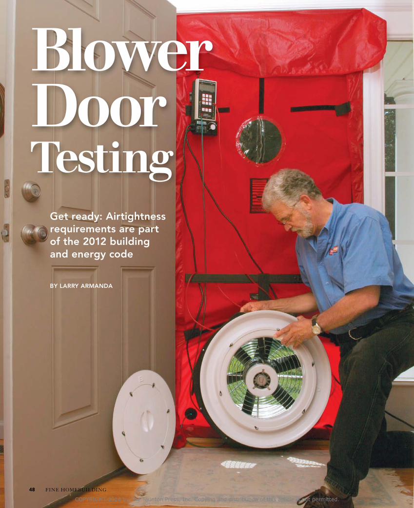
BlowerDoor Testing
Get ready: Airtightness requirements are part of the 2012 building and energy code
BY LARRY ARMANDA
FINE HOmEBuILDING48
COPYRIGHT 2014 by The Taunton Press, Inc. Copying and distribution of this article is not permitted.
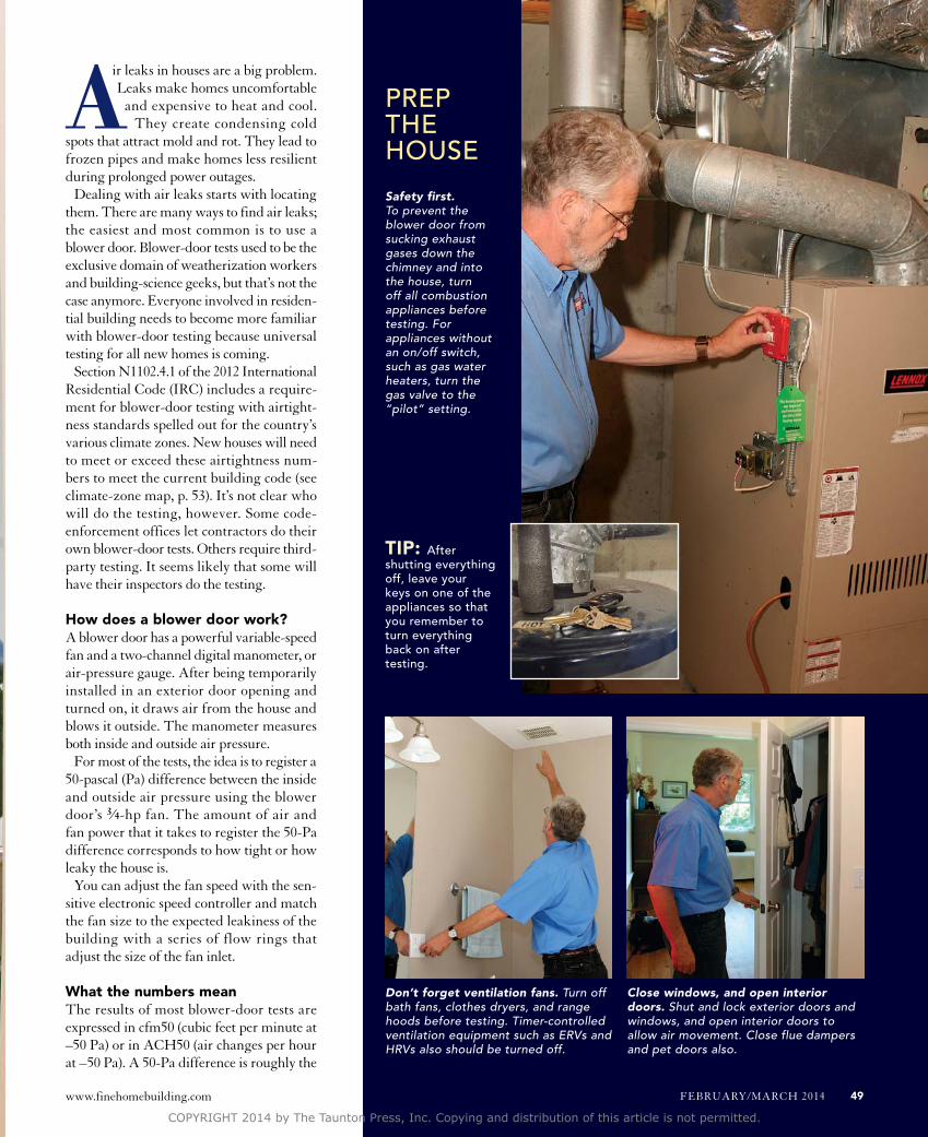
Safety first. To prevent the blower door from sucking exhaust gases down the chimney and into the house, turn off all combustion appliances before testing. For appliances without an on/off switch, such as gas water heaters, turn the gas valve to the “pilot” setting.
Close windows, and open interior doors. Shut and lock exterior doors and windows, and open interior doors to allow air movement. Close flue dampers and pet doors also.
Don’t forget ventilation fans. Turn off bath fans, clothes dryers, and range hoods before testing. Timer-controlled ventilation equipment such as ERVs and HRVs also should be turned off.
Air leaks in houses are a big problem. Leaks make homes uncomfortable and expensive to heat and cool. They create condensing cold
spots that attract mold and rot. They lead to frozen pipes and make homes less resilient during prolonged power outages.
Dealing with air leaks starts with locating them. There are many ways to find air leaks; the easiest and most common is to use a blower door. Blower-door tests used to be the exclusive domain of weatherization workers and building-science geeks, but that’s not the case anymore. Everyone involved in residen-tial building needs to become more familiar with blower-door testing because universal testing for all new homes is coming.
Section N1102.4.1 of the 2012 International Residential Code (IRC) includes a require-ment for blower-door testing with airtight-ness standards spelled out for the country’s various climate zones. New houses will need to meet or exceed these airtightness num-bers to meet the current building code (see climate-zone map, p. 53). It’s not clear who will do the testing, however. Some code-enforcement offices let contractors do their own blower-door tests. Others require third-party testing. It seems likely that some will have their inspectors do the testing.
How does a blower door work?A blower door has a powerful variable-speed fan and a two-channel digital manometer, or air-pressure gauge. After being temporarily installed in an exterior door opening and turned on, it draws air from the house and blows it outside. The manometer measures both inside and outside air pressure.
For most of the tests, the idea is to register a 50-pascal (Pa) difference between the inside and outside air pressure using the blower door’s 3⁄4-hp fan. The amount of air and fan power that it takes to register the 50-Pa difference corresponds to how tight or how leaky the house is.
You can adjust the fan speed with the sen-sitive electronic speed controller and match the fan size to the expected leakiness of the building with a series of flow rings that adjust the size of the fan inlet.
What the numbers meanThe results of most blower-door tests are expressed in cfm50 (cubic feet per minute at –50 Pa) or in ACH50 (air changes per hour at –50 Pa). A 50-Pa difference is roughly the
PreP the house
TIP: After shutting everything off, leave your keys on one of the appliances so that you remember to turn everything back on after testing.
www.finehomebuilding.com FEBRuARY/mARCH 2014 49
COPYRIGHT 2014 by The Taunton Press, Inc. Copying and distribution of this article is not permitted.
equivalent of a 20-mph wind on all sides of the house. The intense pressure from the blower door exaggerates the natural conditions to make air leaks appear more obvious.
The cfm50 measurement refers to how much air is rushing back into the building as the blower door is forcing air out, depressuriz-ing the house. A good number here would be about 800 cfm50 or 900 cfm50 for a 2000-sq.-ft. house.
ACH50 measures how many times the air in the house is completely replaced in one hour under the blower door’s artificial 50-Pa pressure difference. most building-science and weatherization professionals consider about 3 ACH50 to be the sweet spot between a house that’s too tight and one that’s too leaky. Leakier homes should have air- sealing work to make them more energy efficient, while tighter homes may need mechanical ventilation to control indoor-air pollutants.
Blower-door tests are useful for both new and existing homes. Old homes are often tested to direct weatherization efforts and to gauge the effectiveness of those efforts. New homes are often tested as part of Energy Star and other home-performance certifications.
Preparing for the testThe most important step in preparing for a blower-door test is to turn off all combustion appliances (furnaces, boilers, and water heat-ers). If you don’t, the blower door’s powerful fan could suck flue gases, including carbon monoxide, down the chimney and into the house, creating a dangerous condition called backdrafting. For appli-ances equipped with a switch, I simply turn them off. If an appliance doesn’t have a switch—for example, most gas water heaters—I turn the gas valve to the “pilot” setting.
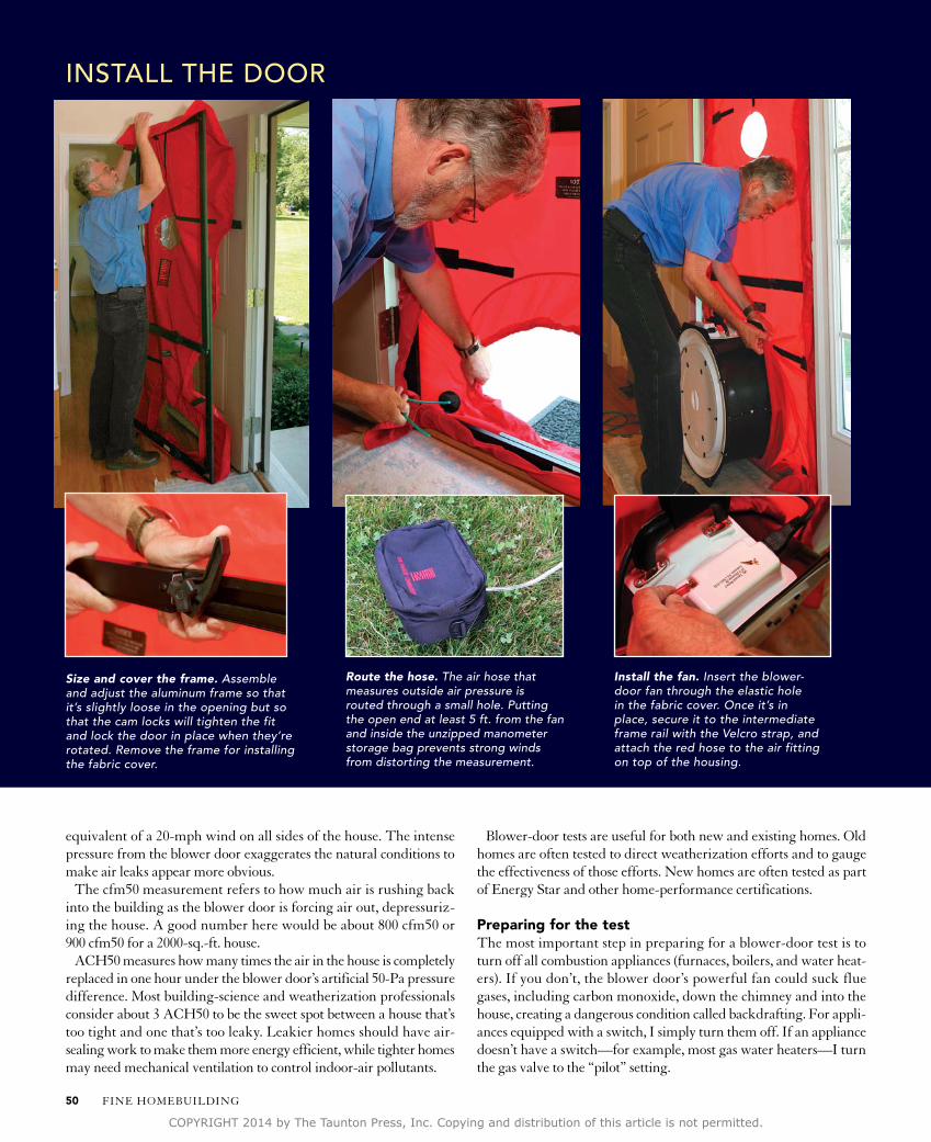
Route the hose. The air hose that measures outside air pressure is routed through a small hole. Putting the open end at least 5 ft. from the fan and inside the unzipped manometer storage bag prevents strong winds from distorting the measurement.
Install the fan. Insert the blower-door fan through the elastic hole in the fabric cover. Once it’s in place, secure it to the intermediate frame rail with the Velcro strap, and attach the red hose to the air fitting on top of the housing.
instAll the door
Size and cover the frame. Assemble and adjust the aluminum frame so that it’s slightly loose in the opening but so that the cam locks will tighten the fit and lock the door in place when they’re rotated. Remove the frame for installing the fabric cover.
FINE HOmEBuILDING50
COPYRIGHT 2014 by The Taunton Press, Inc. Copying and distribution of this article is not permitted.
After shutting off everything, I leave my keys on one of the appli-ances so that I remember to turn everything back on after I’m done with the testing.
Next, I shut and lock all windows and exterior doors. This includes garage doors on attached garages. I leave open interior doors, includ-ing closet doors, to allow the free movement of interior air. When the basement is included as part of the home’s conditioned space, I also open the basement door.
Fires in woodstoves and fireplaces must be extinguished for at least 24 hours before testing, and fireplace doors and chimney dampers should be closed. It’s also important to turn off clothes dryers, ventila-tion fans, and air conditioners.
I also look around for broken plaster and loose wall paneling. If the home has a drop ceiling, I always check above the tiles for holes.
If I find any, I remove a few ceiling panels so that the blower door doesn’t pull down the entire ceiling. I also take a good look at any vinyl flooring, even tile, because moving air can pull it from the floor during the test.
Setting up the doorThe minneapolis Blower Door (energyconservatory.com) I use is packed in three parts. The adjustable aluminum frame that supports the motor is packed in a nylon carrying bag. The manometer, air hoses, and fabric cover are in a second bag. The fan, which is pro-tected by its plastic housing, is carried separately. The whole rig sells for about $2700.
I begin setting up the blower door by assembling the metal frame on the floor. Doing this on a rug or a blanket prevents scratching the
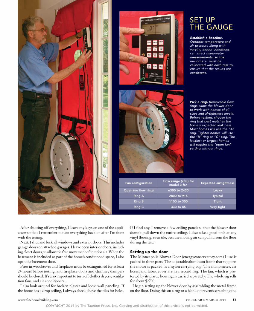
Pick a ring. Removable flow rings allow the blower door to work with homes of all sizes and airtightness levels. Before testing, choose the ring that best matches the home’s expected leakiness. Most homes will use the “A” ring. Tighter homes will use the “B” ring or “C” ring. The leakiest or largest homes will require the “open fan” setting without rings.
set uP the GAuGe
Fan configurationFlow range (cfm) for
model 3 fanExpected airtightness
Open (no flow ring) 6300 to 2430 Leaky
Ring A 2800 to 915 Typical
Ring B 1100 to 300 Tight
Ring C 330 to 85 Very tight
Establish a baseline. Outdoor temperature and air pressure along with varying indoor conditions can affect manometer measurements, so the manometer must be calibrated with each test to ensure that the results are consistent.
www.finehomebuilding.com FEBRuARY/mARCH 2014 51
COPYRIGHT 2014 by The Taunton Press, Inc. Copying and distribution of this article is not permitted.

floor. Once the frame is together, I fit it in the doorway where I’ll be conducting the test. I choose a centrally located exterior door free of obstructions that could block airflow.
I first adjust the frame width, and then I adjust the height. I tighten the adjustment knobs so that when the cam-shaped locking levers are fully tightened, they exert enough pressure to make a tight seal around the door.
Once the frame is sized, I remove it from the door opening. I lay the nylon cover on the floor with the manufacturer’s label on the fabric cover facing up, and then place the frame on top of the cover, securing it with the attached Velcro tabs. I now return the covered frame to the opening and press it tight to the stops on the door jamb. Then I lock the frame in place using the locking levers.
Next, I hang the speed controller and the digital manometer from the frame using the provided bracket. The green air hose runs outside through the small hole provided in the fabric cover.
The fan fits through the large hole in the cover. A wide Velcro strap attached to the intermediate frame rail helps to hold the heavy unit in place.
After making sure that the speed controller is in the off position, I connect it to the fan and plug the other end into a house receptacle. I then connect the green air hose running outside to the “Ref” tap on the A-side of the manometer. The red hose runs from the air-pressure tap on the top of the fan to the “Input” tap on the B-side of the manometer.
Set up the gaugeWith the fan cover and all flow rings in place on the fan housing, I turn on the manometer with the “On/Off” button. I then press the “mode” button twice to choose the “PR/FL@50 mode” so that the gauge will display results based on –50 Pa even if the actual pressure is greater or less.
I do this for two reasons: First, some leaky homes simply won’t get to –50 Pa; the fan just can’t move enough air to depressurize them to this amount. more commonly, though, it’s so that I don’t waste time adjusting the fan speed to get to exactly –50 Pa. Instead, the gauge uses the current reading to extrapolate cfm to the –50-Pa benchmark. I shoot for between –45 Pa and –55 Pa for the most accu rate test.
I now calibrate the gauge to current outdoor conditions and elimi-nate pressure differences caused by the stack effect inside the house. This step, described as “establishing baseline,” makes the test useful in all times of the year and makes the results repeatable. The process, which involves a series of keystrokes on the manometer, is explained in the blower-door manufacturer’s “Quick Guide.”
Pick a flow ringThis next step requires experience or additional experimentation. You have to guess which flow ring on the fan housing best matches the expected leakiness of the house (chart, p. 51).
most modern, conventionally built houses from about 1600 sq. ft. to 2500 sq. ft. will use the “A” ring. Tighter homes will use a smaller ring. Especially leaky homes will use “open fan,” which describes the fan without any flow rings.
If you choose wrong, it’s no big deal, but with every guess, you need to reconfigure the gauge to match the flow ring you’ve selected. For the test shown here, the “A” ring is in place. Before starting your own test, be sure to confirm that the gauge is set up correctly by pressing
Start slowly. Gradually increase the fan speed with the controller until the manometer reaches about –25 Pa. Walk around the house to look for problems such as blowing fireplace ash or lifting vinyl flooring. If everything’s OK, increase the speed to reach –50 Pa, then record the results.
stArt testinG
Photo far right, facing page: Rodney Diaz. Drawing facing page: Dan Thornton.
FINE HOmEBuILDING52
COPYRIGHT 2014 by The Taunton Press, Inc. Copying and distribution of this article is not permitted.
In addition to testing airtightness, blower doors can
be used to track down air leaks. One common way is
to use a smoke puffer (left), which shows leaks with
a chemical smoke. If you want to see air leaks behind
walls, you’ll need to use an infrared camera. Unfortu-
nately, you’ll need a 10°F to 20°F temperature differ-
ence between inside and outside air for the leaks to
show up. The IR image at right shows how the blower
door is drawing hot attic air into stud cavities.
Finding leaks
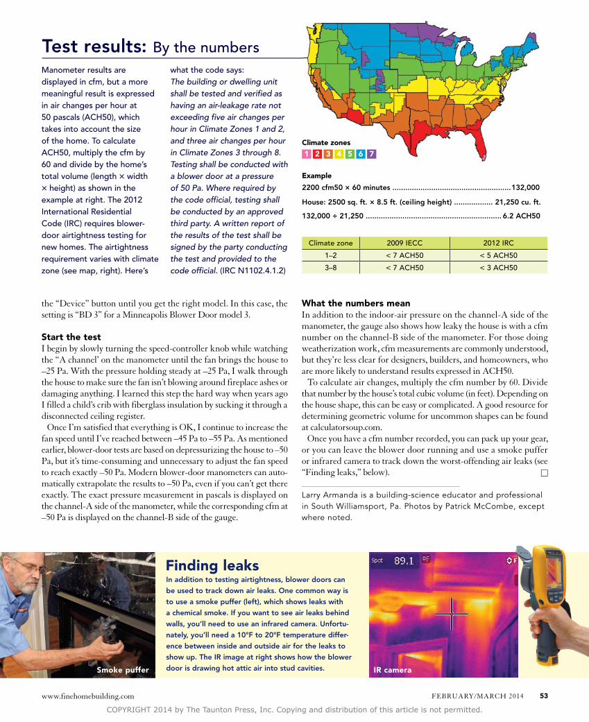
Test results: By the numbersManometer results are displayed in cfm, but a more meaningful result is expressed in air changes per hour at 50 pascals (ACh50), which takes into account the size of the home. to calculate ACh50, multiply the cfm by 60 and divide by the home’s total volume (length × width × height) as shown in the example at right. the 2012 international residential Code (irC) requires blower-door airtightness testing for new homes. the airtightness requirement varies with climate zone (see map, right). here’s
what the code says:The building or dwelling unit shall be tested and verified as having an air-leakage rate not exceeding five air changes per hour in Climate Zones 1 and 2, and three air changes per hour in Climate Zones 3 through 8. Testing shall be conducted with a blower door at a pressure of 50 Pa. Where required by the code official, testing shall be conducted by an approved third party. A written report of the results of the test shall be signed by the party conducting the test and provided to the code official. (irC n1102.4.1.2)
Example
2200 cfm50 × 60 minutes .......................................................132,000
House: 2500 sq. ft. × 8.5 ft. (ceiling height) .................. 21,250 cu. ft.
132,000 ÷ 21,250 ............................................................... 6.2 ACH50
Climate zone 2009 ieCC 2012 irC
1–2 < 7 ACh50 < 5 ACh50
3–8 < 7 ACh50 < 3 ACh50
the “Device” button until you get the right model. In this case, the setting is “BD 3” for a minneapolis Blower Door model 3.
Start the testI begin by slowly turning the speed-controller knob while watching the “A channel’ on the manometer until the fan brings the house to –25 Pa. With the pressure holding steady at –25 Pa, I walk through the house to make sure the fan isn’t blowing around fireplace ashes or damaging anything. I learned this step the hard way when years ago I filled a child’s crib with fiberglass insulation by sucking it through a disconnected ceiling register.
Once I’m satisfied that everything is OK, I continue to increase the fan speed until I’ve reached between –45 Pa to –55 Pa. As mentioned earlier, blower-door tests are based on depressurizing the house to –50 Pa, but it’s time-consuming and unnecessary to adjust the fan speed to reach exactly –50 Pa. modern blower-door manometers can auto-matically extrapolate the results to –50 Pa, even if you can’t get there exactly. The exact pressure measurement in pascals is displayed on the channel-A side of the manometer, while the corresponding cfm at –50 Pa is displayed on the channel-B side of the gauge.
What the numbers meanIn addition to the indoor-air pressure on the channel-A side of the manometer, the gauge also shows how leaky the house is with a cfm number on the channel-B side of the manometer. For those doing weatherization work, cfm measurements are commonly understood, but they’re less clear for designers, builders, and homeowners, who are more likely to understand results expressed in ACH50.
To calculate air changes, multiply the cfm number by 60. Divide that number by the house’s total cubic volume (in feet). Depending on the house shape, this can be easy or complicated. A good resource for determining geometric volume for uncommon shapes can be found at calculatorsoup.com.
Once you have a cfm number recorded, you can pack up your gear, or you can leave the blower door running and use a smoke puffer or infrared camera to track down the worst-offending air leaks (see “Finding leaks,” below). □
Larry Armanda is a building-science educator and professional in South Williamsport, Pa. Photos by Patrick McCombe, except where noted.
Smoke puffer IR camera
Climate zones
1 2 3 4 5 6 7
www.finehomebuilding.com FEBRuARY/mARCH 2014 53
COPYRIGHT 2014 by The Taunton Press, Inc. Copying and distribution of this article is not permitted.