blossom-quad: a non-uniform quadrilateral mesh …gmsh.info/doc/preprints/gmsh_quad_preprint.pdf ·...
TRANSCRIPT

INTERNATIONAL JOURNAL FOR NUMERICAL METHODS IN ENGINEERINGInt. J. Numer. Meth. Engng 2010; 00:1–6 Prepared using nmeauth.cls [Version: 2002/09/18 v2.02]
Blossom-Quad: a non-uniform quadrilateral mesh generator usinga minimum cost perfect matching algorithm
J.-F. Remacle1∗, J. Lambrechts1, B. Seny1, E. Marchandise1, A. Johnen2 andC. Geuzaine2
1 Universite catholique de Louvain, Institute of Mechanics, Materials and Civil Engineering (iMMC),Batiment Euler, Avenue Georges Lemaıtre 4, 1348 Louvain-la-Neuve, Belgium
2 Universite de Liege, Department of Electrical Engineering and Computer Science, Montefiore InstituteB28, Grande Traverse 10, 4000 Liege, Belgium
SUMMARY
A new indirect way of producing all-quad meshes is presented. The method takes advantage of a wellknown algorithm of the graph theory, namely the Blossom algorithm that computes the minimumcost perfect matching in a graph in polynomial time. The new Blossom-Quad algorithm is comparedwith standard indirect procedures. Meshes produced by the new approach are better both in terms ofelement shape and in terms of size field efficiency. Copyright c© 2010 John Wiley & Sons, Ltd.
key words: quadrilateral meshing; surface remeshing; graph theory; optimization; perfect matching
1. Introduction
Quadrilateral surface meshes are sometimes considered as superior to triangular meshes forfinite element simulations. Discussions about if and why quadrilaterals are better than trianglesare usually passionate in the finite element community. We will not try to argue about thatthorny question here—but we assume that quadrilateral meshes are indeed useful and in thispaper we present a new way of generating such meshes.
Let us first briefly recall which kinds of methods can be used to build non uniformquadrilateral meshes in an automatic manner. There are essentially two categories of methods.
In direct methods, the quadrilaterals are constructed at once, either using some kind ofadvancing front technique [1] or using regular grid-based methods (quadtrees). Advancing frontmethods for quads are considered to be non robust and quadtree methods usually produce lowquality elements close to the boundaries of the domain and are unable to fulfill general sizeconstraints (anisotropy, strong variations).
In indirect methods, a triangular mesh is built first. Triangle-merge methods then use thetriangles of the initial mesh and recombine them to form quadrangles [2, 3]. Other moresophisticated indirect methods use a mix of advancing front and triangle merge [4].
∗Correspondence to: [email protected]
ReceivedCopyright c© 2010 John Wiley & Sons, Ltd. Revised
2 J.-F. REMACLE ET AL.
The method we present here is an indirect approach to quadrilateralization. We make use ofa famous algorithm of the theory of graphs: the Blossom algorithm, proposed by Edmonds in1965 [5, 6], which allows to find the minimal cost perfect matching of a given graph. The newmethod has some clear advantages: (i) it provides a mesh that is guaranteed to be quadrilateralonly, (ii) it is optimal in a certain way and (iii) it is fast.
2. Mesh quality measures
The aim of the mesh generation process described in this paper is to build a mesh made ofquadrilaterals that has controlled element sizes and shapes. We are interested in generatingnon uniform quadrilateral meshes. Local information about sizes is given through the definitionof a mesh size field that returns, for every point ~x in the domain, a “characteristic” lengthh(~x) that has to be fulfilled by the mesh.
Let ~a and ~b be two points of R3. The adimensional length of the vector−→ab with respect to
the non uniform size field h is defined as [7, 3]:
lh(−→ab) =
∥∥∥−→ab∥∥∥ 1∫0
1
h(−→a + t−→ab)
dt. (1)
An optimum mesh in term of the size is a mesh for which every edge i is of adimensional sizelhi equal to one. It is of course impossible to have such a perfect unit mesh. Here, we define theefficiency index [7] τ of a mesh as the exponential of the mean value of the difference betweeneach edge length lhi and one:
τ [%] = 100 exp
(1
ne
ne∑i=1
di
), (2)
with di = lhi − 1 if lhi < 1, di =1
lhi− 1 if lhi > 1 and ne the number of edges in the mesh.
Surface mesh algorithms usually produce triangular meshes with typical values of τ aroundτ = 85%, i.e., with non-dimensional sizes around 1/
√2 ≤ lhi ≤
√2.
Having the right sizing for the mesh is not enough: mesh generators should also providemeshes with controlled element qualities. We then define a quality measure for quadrilateralelements. Consider a quadrilateral element q and its the four internal angles αk, k = 1, 2, 3, 4.We define the quality η(q) of q as:
η(q) = max
(1− 2
πmax
k
(∣∣∣π2− αk
∣∣∣), 0). (3)
This quality measure is 1 if the element is a perfect quadrilateral and is 0 if one of those anglesis either ≤ 0 or ≥ π. In what follows, we will present statistics for the quadrilateral meshes:
• The efficiency index τ , which measures the adequacy of the mesh with the mesh size field.The index τ is smaller or equal to one, and should be as close as possible to τ = 100%.
• The average element quality η as well as the worst element quality ηw, which can beimportant in the context of finite element simulations.
Copyright c© 2010 John Wiley & Sons, Ltd. Int. J. Numer. Meth. Engng 2010; 00:1–6Prepared using nmeauth.cls

QUADRILATERAL MESH GENERATION USING PERFECT MATCHING 3
3. Indirect quadrilateralization using a non-optimal matching algorithmIn §1 we have made the distinction between direct and indirect methods for the constructionof quadrilateral meshes. In the case of indirect methods, a triangular mesh is first constructed.Then, triangles are recombined in order to produce quadrangles.
Consider a triangular mesh made of nt triangles ti, i = 1, . . . nt. In what follows, we considerinternal edges eij of the mesh that are common to triangles ti and tj . We define a cost functionc(eij) = 1− η(qij) that is associated to each graph edge eij of the mesh and that is defined asthe mesh quality of the quadrilateral qij that is formed by merging the two adjacent trianglesti and tj . Usual indirect quadrilateralization procedures work as follows [3]. Edges eij of thegraph are sorted with respect to their individual cost functions. Then, the two triangles thatare adjacent to the best edge eij of the list are recombined into a quadrilateral. Triangles tiand tj are tagged in order to prevent other edges that are adjacent either to ti or to tj to beused for another quadrilateral forming. Then, the algorithm processes the ordered list of edges,forming quadrilaterals with triangles adjacent to an edge as long as none of those adjacenttriangles are tagged. Fig. 1 shows an illustration of this procedure for a rectangular domain ofsize 1× 3 and a mesh size field defined by
h(x, y) = 0.1 + 0.08 sin(3x) cos(6y).
Isolated triangles inevitably remain in the mesh and the resulting mesh is not made ofquadrilaterals only. The mesh is then said to be quad-dominant. In the example of Fig. 1,the resulting mesh is made of 836 quads and 240 triangles.
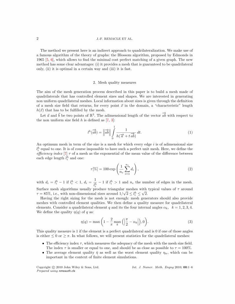
A mesh composed of quadrilaterals can be build subsequently using a uniform meshrefinement procedure [3]. Every quadrilateral of the quad-dominant mesh is split into foursub-quadrilaterals and every triangle is split into three sub-quadrilaterals (see Fig. 2). In orderto fulfill the size criterion h(~x), the initial triangular mesh should thus be built using a sizefield with twice the value (i.e. 2h) that is expected in the final mesh.
The recombination process just described is sub-optimal. It does not provide the best set ofedges to be recombined with respect to some general cost function. Indeed, the only optimalityproperty of this algorithm is that it ensures that the best triangle pair will be recombined.
The second part of the algorithm, namely the mesh refinement step, also has some drawbacks.Splitting every element of the mesh produces a mesh that has half the size of the initial mesh.It is of course possible to generate an initial mesh with double the required size. Yet, with realgeometries, the new vertices will have to be added on the geometry, which is not trivial. Onthe other hand, the refinement step does not allow a sharp control of the mesh size. On Fig. 2,the procedure ends with an efficiency index of 79%, which cannot be considered as good.
In [2] the authors propose a scheme for recombining triangular meshes that does not alwaysrequire the refinement step, using a kind of advancing front technique. The merging of trianglesstarts at the boundary; when a front closes, the algorithm attempts to maintain an even numberof triangles on any sub-front. Again, this approach is sub-optimal because the result dependson the ordering of elements and on the choice of the initial front.
Copyright c© 2010 John Wiley & Sons, Ltd. Int. J. Numer. Meth. Engng 2010; 00:1–6Prepared using nmeauth.cls

4 J.-F. REMACLE ET AL.
τ = 88.9% τ = 85.6%
Figure 1. Illustration of the quad-dominant algorithm. Left mesh is the initial triangular mesh andright mesh is the quad dominant mesh, after smoothing (triangles are in grey).
4. The new Blossom-Quad algorithm
Here, our aim is to build a mesh generation scheme that starts with a triangular mesh andattempts to find the set of pairs of triangles that form the best possible quadrilaterals withthe constraint of not leaving any remaining triangle in the mesh.
4.1. Blossom: a minimum cost perfect matching algorithm
Let us consider G(V,E, c) an undirected weighted graph. Here, V is the set of nV vertices,E is the set of nE undirected edges and c(E) =
∑c(eij) is an edge-based cost function, i.e.,
the sum of all weights associated to every edge eij ∈ E of the graph. A matching is a subsetE′ ⊆ E such that each node of V has at most one incident edge in E′. A matching is said tobe perfect if each node of V has exactly one incident edge in E′. As a consequence, a perfectmatching contains exactly nE′ = nV /2 edges. A perfect matching can therefore only be foundfor graphs with an even number of vertices. A matching is optimum if c(E′) is minimum amongall possible perfect matchings.
In 1965, Edmonds [8, 5] invented the Blossom algorithm that solves the problem of optimum
Copyright c© 2010 John Wiley & Sons, Ltd. Int. J. Numer. Meth. Engng 2010; 00:1–6Prepared using nmeauth.cls
QUADRILATERAL MESH GENERATION USING PERFECT MATCHING 5
τ = 85.5% τ = 83.9% τ = 79.1%
Figure 2. A quad dominant algorithm using halgo = 2h followed by a one mesh refinement procedureleads to a reduction of the efficiency index τ .
perfect matching in polynomial time. A straightforward implementation of Edmonds’salgorithm requires O(n2V nE) operations.
Since then, the worst-case complexity of the Blossom algorithm has been steadily improving.Both Lawler [9] and Gabow [10] achieved a running time ofO(n3V ). Galil, Micali and Gabow [11]improved it to O(nV nE log(nV )). The current best known result in terms of nV and nE isO(nV (nE + log nV )) [12].
There is also a long history of computer implementations of the Blossom algorithm,starting with the Blossom I code of Edmonds, Johnson and Lockhart [6]. In this paper, ourimplementation makes use of the Blossom IV code of Cook and Rohe [13]†, which has beenconsidered for several years as the fastest available implementation of the Blossom algorithm.
4.2. Optimal triangle merging
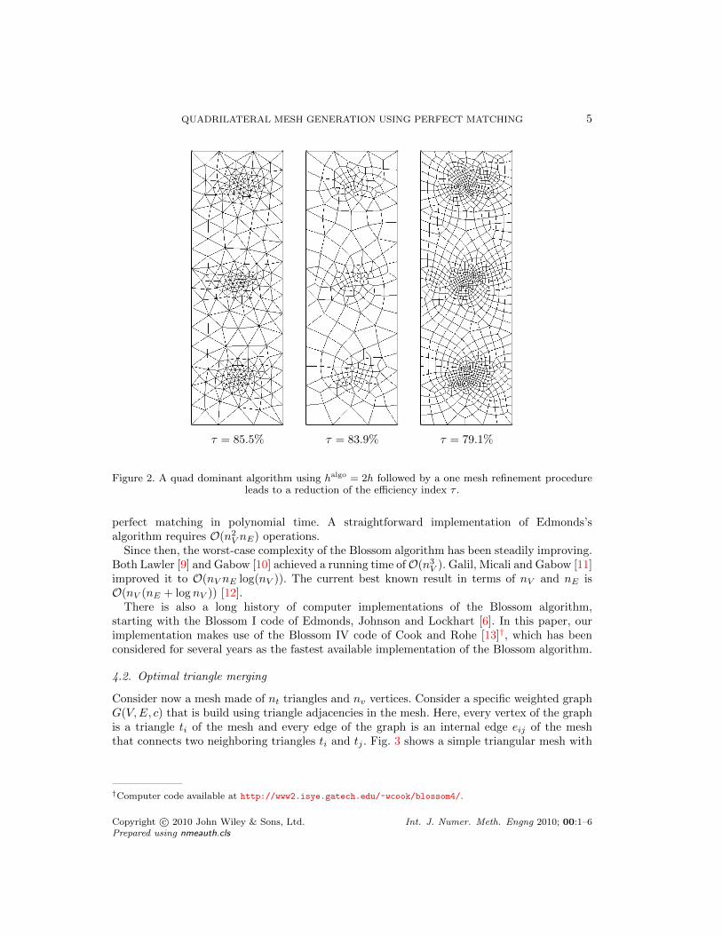
Consider now a mesh made of nt triangles and nv vertices. Consider a specific weighted graphG(V,E, c) that is build using triangle adjacencies in the mesh. Here, every vertex of the graphis a triangle ti of the mesh and every edge of the graph is an internal edge eij of the meshthat connects two neighboring triangles ti and tj . Fig. 3 shows a simple triangular mesh with
†Computer code available at http://www2.isye.gatech.edu/~wcook/blossom4/.
Copyright c© 2010 John Wiley & Sons, Ltd. Int. J. Numer. Meth. Engng 2010; 00:1–6Prepared using nmeauth.cls

6 J.-F. REMACLE ET AL.
eij
ti
tj
Figure 3. A mesh (in black) and its graph (in cyan and red). The set of graph edges colored in redforms a perfect matching.
its graph and one perfect matching.Let us come back first to the non-optimal triangle merging algorithms of §3. In term of what
has just been defined, the subset E′ of edges that have been used for triangle merging in theapproach of [3] is a matching that is very rarely a perfect matching. The one of [2] is usuallya perfect matching, but not necessarily the optimal one.
Here, we propose a new indirect approach to quadrilateral meshing that takes advantageof the Blossom algorithm of Edmonds. To this end we apply the Blossom IV algorithm tothe graph of the mesh. We intend to find the optimum perfect matching with respect to thefollowing total cost function
c =∑e∈E′
(1− η(qij)), (4)
that is, the sum of all elementary cost functions (or “badnesses”) of the quadrilaterals thatresult in the merging of the edges of the perfect matching E′.
An obvious requirement for the final mesh to be quadrilateral only is that the initialtriangular mesh contains an even number of triangles (i.e., an even number of graph vertices).Euler’s formula for planar triangulations states that the number of triangles in the mesh is
nt = 2(nv − 1)− nbv, (5)
where nbv is the number of mesh nodes on its boundary. So, the number of mesh points onthe boundary nbv should be even. Here our algorithms are applied to general solid models that
Copyright c© 2010 John Wiley & Sons, Ltd. Int. J. Numer. Meth. Engng 2010; 00:1–6Prepared using nmeauth.cls
QUADRILATERAL MESH GENERATION USING PERFECT MATCHING 7
have a boundary representation (BRep) [14]. This means that model surfaces are bounded byconnected model edges that form edge loops and that the model edges are bounded by modelvertices. The mesh vertices of a model edge nbiv are defined as the mesh vertices on that edgeminus the model vertices. The total number of mesh points on the boundary nbv can thus bewritten as:
nbv =
NE∑i=0
(1 + nbiv ). (6)
It is then easy to see that for nbv to be even, it is sufficient for nbiv to be odd. This means that asufficient condition for having an even number of triangles in the mesh is to have every modeledge bi discretized with an odd number of mesh vertices.
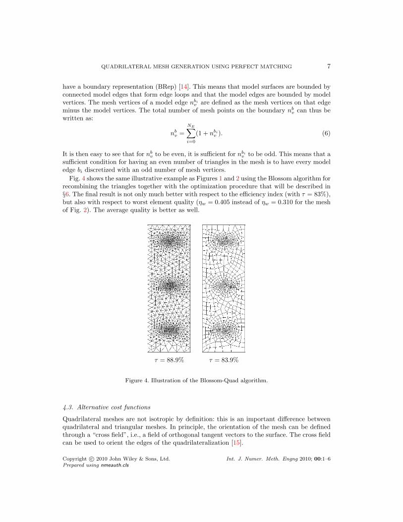
Fig. 4 shows the same illustrative example as Figures 1 and 2 using the Blossom algorithm forrecombining the triangles together with the optimization procedure that will be described in§6. The final result is not only much better with respect to the efficiency index (with τ = 83%),but also with respect to worst element quality (ηw = 0.405 instead of ηw = 0.310 for the meshof Fig. 2). The average quality is better as well.
τ = 88.9% τ = 83.9%
Figure 4. Illustration of the Blossom-Quad algorithm.
4.3. Alternative cost functions
Quadrilateral meshes are not isotropic by definition: this is an important difference betweenquadrilateral and triangular meshes. In principle, the orientation of the mesh can be definedthrough a “cross field”, i.e., a field of orthogonal tangent vectors to the surface. The cross fieldcan be used to orient the edges of the quadrilateralization [15].
Copyright c© 2010 John Wiley & Sons, Ltd. Int. J. Numer. Meth. Engng 2010; 00:1–6Prepared using nmeauth.cls
8 J.-F. REMACLE ET AL.
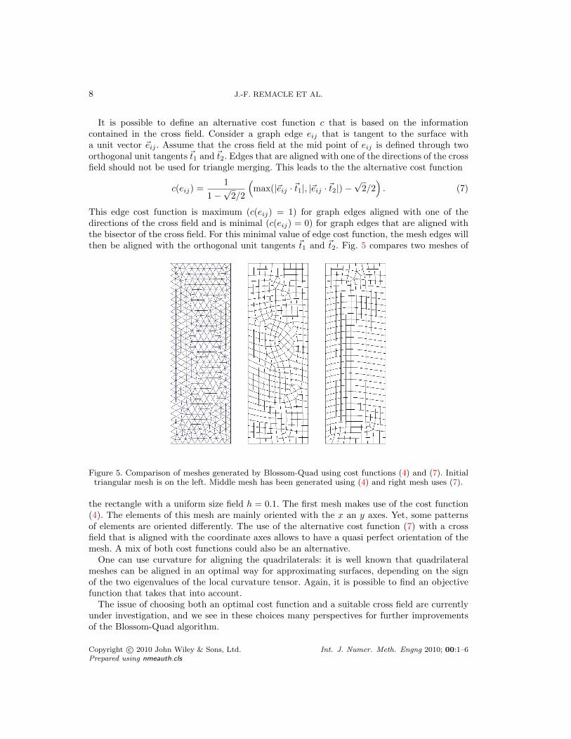
It is possible to define an alternative cost function c that is based on the informationcontained in the cross field. Consider a graph edge eij that is tangent to the surface witha unit vector ~eij . Assume that the cross field at the mid point of eij is defined through twoorthogonal unit tangents ~t1 and ~t2. Edges that are aligned with one of the directions of the crossfield should not be used for triangle merging. This leads to the the alternative cost function
c(eij) =1
1−√
2/2
(max(|~eij · ~t1|, |~eij · ~t2|)−
√2/2). (7)
This edge cost function is maximum (c(eij) = 1) for graph edges aligned with one of thedirections of the cross field and is minimal (c(eij) = 0) for graph edges that are aligned withthe bisector of the cross field. For this minimal value of edge cost function, the mesh edges willthen be aligned with the orthogonal unit tangents ~t1 and ~t2. Fig. 5 compares two meshes of
Figure 5. Comparison of meshes generated by Blossom-Quad using cost functions (4) and (7). Initialtriangular mesh is on the left. Middle mesh has been generated using (4) and right mesh uses (7).
the rectangle with a uniform size field h = 0.1. The first mesh makes use of the cost function(4). The elements of this mesh are mainly oriented with the x an y axes. Yet, some patternsof elements are oriented differently. The use of the alternative cost function (7) with a crossfield that is aligned with the coordinate axes allows to have a quasi perfect orientation of themesh. A mix of both cost functions could also be an alternative.
One can use curvature for aligning the quadrilaterals: it is well known that quadrilateralmeshes can be aligned in an optimal way for approximating surfaces, depending on the signof the two eigenvalues of the local curvature tensor. Again, it is possible to find an objectivefunction that takes that into account.
The issue of choosing both an optimal cost function and a suitable cross field are currentlyunder investigation, and we see in these choices many perspectives for further improvementsof the Blossom-Quad algorithm.
Copyright c© 2010 John Wiley & Sons, Ltd. Int. J. Numer. Meth. Engng 2010; 00:1–6Prepared using nmeauth.cls

QUADRILATERAL MESH GENERATION USING PERFECT MATCHING 9
5. Existence of perfect matchings
If for some graphs it is possible to find different perfect matchings, there is in general noguarantee that even one single perfect matching exists in a given graph. Consider the meshesof Fig. 6. It is obvious that no perfect matching exists for the coarsest one. The followingresult, known as Tutte’s theorem, proves that none of the two meshes of Fig. 6 contains aperfect matching.
Figure 6. Triangulations that have no perfect matching.
Tutte’s theorem : A graph G = (V,E) has no perfect matching if and only if there is a setS ⊆ V whose removal results in more odd-sized components than the cardinality nS of S, i.e.,the number of elements in S [16, 17].
In other words, Tutte’s theorem says that there is no perfect matching in a triangulation ifand only if it is possible to remove nS triangles from the mesh and create more that nS nonconnected regions that have an odd-sized number of triangles. Let us use Tutte’s theorem toprove that none of the two meshes of Fig. 6 has a perfect matching. Let us consider the set S oftriangles that have their tip pointed downwards. In the coarsest mesh, nS = 1 and 3 odd-sizedcomponents are created, which proves that no perfect matching exists. In the second one, 6triangles are removed and 10 odd-sized components are created. This simple pattern can berepeated to produce meshes of arbitrary sizes that have no perfect matchings.
The general problem of counting the number of perfect matchings in a general graph is#P-complete‡. In other words, there is no hope to find the number of perfect matchings ina general graph. (There is a way to find out, in polynomial time, wether a perfect matchingexists by detecting a breakdown in the Blossom algorithm.)
There are however some interesting special cases.
‡Sharp p-complete, i.e. much harder than NP-complete.
Copyright c© 2010 John Wiley & Sons, Ltd. Int. J. Numer. Meth. Engng 2010; 00:1–6Prepared using nmeauth.cls

10 J.-F. REMACLE ET AL.
5.1. Planar Graphs
A graph is said to be planar if it can be drawn in the 2D plane in such a way that its edgesintersect only at its vertices. There exists an efficient algorithm (i.e., in polynomial time) thatcounts perfect matchings in a planar graph. In planar graphs, graph edges form closed nonoverlapping loops that form the graph faces. Let G be a planar graph. Then G can be orientedefficiently so that each face has an odd number of lines oriented clockwise (this orientation iscalled a Pfaffian orientation of G) [18]. It can be proven that counting the number of perfectmatchings can be done by computing the determinant of the Kasteleyn matrix K:
(# of perfect matchings of G)2 = det(K), (8)
where the Kasteleyn matrix K(G) is an adjacency matrix defined as follows. Consider an edgeeij . If eij is oriented positively, then Kij = 1 and Kji = −1. If eij is oriented negatively, thenKij = −1 and Kji = 1. If no edge exists between i and j, then Kij = Kji = 0.
Here, the computation of the determinant can be done in polynomial time so that it is quiteeasy to count matchings in a triangular mesh. It is therefore possible to compute wether aperfect matching exists in any planar graph. Yet, finding out that no perfect matching existsdoes not help us a lot at this point. Moreover, the mesh of a whole torus does not lead to aplanar graph§.
5.2. Cubic Graphs
Cubic graphs, also called trivalent graphs, are graphs for which every node has exactly 3adjacent nodes. Every cubic graph has at least one perfect matching [19]. It can be proventhat the number of perfect matchings in a cubic graph grows exponentially with nV .
In a finite element triangulation, most of the triangles of the mesh have three neighbors.Only the triangles that are on the boundary of the domain have less than three neighbors.Thus, in general, a finite element mesh is close to be trivalent. We then expect intuitivelythat perfect matchings will exist in most finite element triangulations. Even though most ofthe triangulations that we have tried have a perfect matching, the Blossom algorithm hasencountered a break down for some of the meshes we have tried.
Since cubic graphs always have many perfect matchings, we propose in the Blossom-Quadalgorithm to add some extra-edges to the graph with the aim of creating a graph topologythat is close to be trivalent, and thus increase the chance of finding perfect matchings.
5.3. Extra-edges
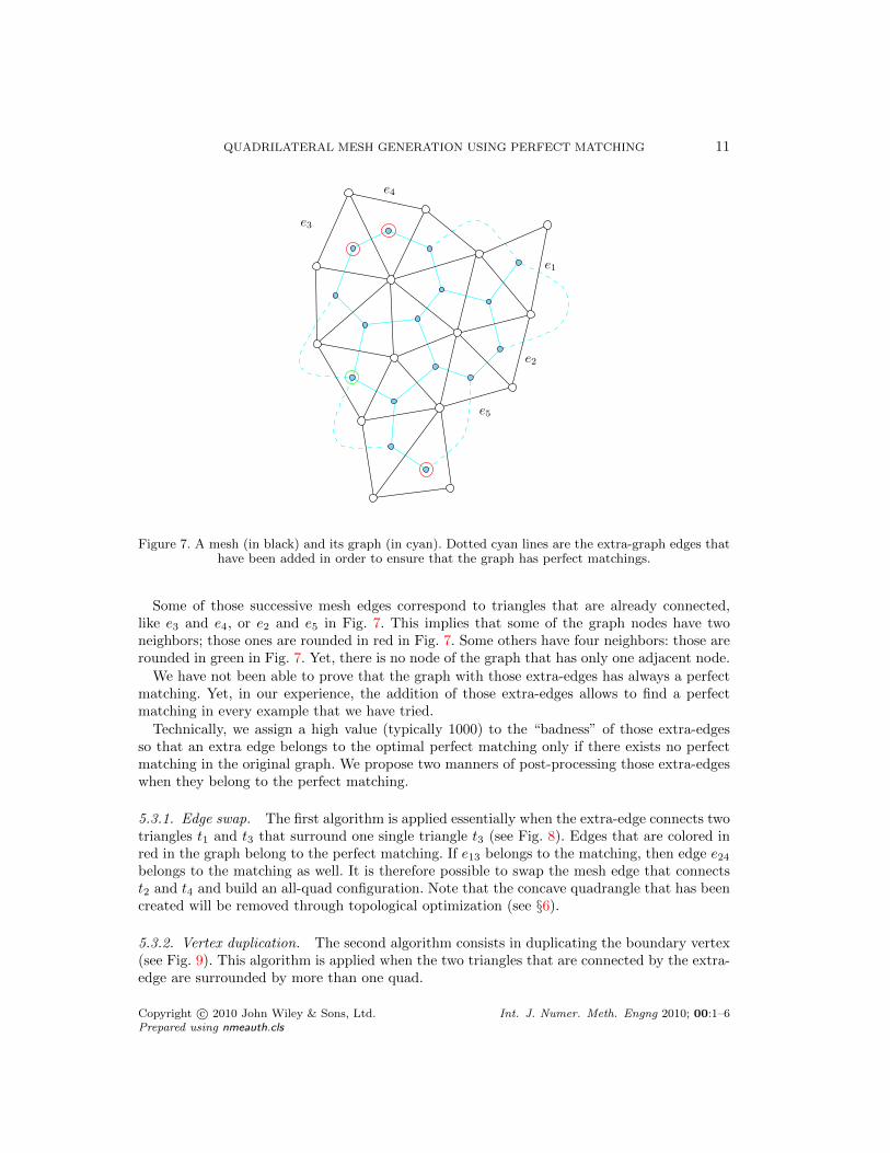
In our approach, we propose to add edges (that we call “extra-edges” in what follows) inthe graph of the triangulation in a way that maximizes the chance of existence of a perfectmatching. Consider two successive mesh edges on the boundary of the domain. If those edgesare like e1 and e2 (Fig. 7), their neighboring triangles are not connected in the graph. At thispoint, we add an extra-edge for every pair of triangles that are adjacent to those edges thatare successive in the boundary of the domain. Those new connexions are represented as dottedcyan lines in Fig. 7.
§The mesh of a complete sphere is planar, even though it is not intuitive.
Copyright c© 2010 John Wiley & Sons, Ltd. Int. J. Numer. Meth. Engng 2010; 00:1–6Prepared using nmeauth.cls
QUADRILATERAL MESH GENERATION USING PERFECT MATCHING 11
e4
e1
e5
e3
e2
Figure 7. A mesh (in black) and its graph (in cyan). Dotted cyan lines are the extra-graph edges thathave been added in order to ensure that the graph has perfect matchings.
Some of those successive mesh edges correspond to triangles that are already connected,like e3 and e4, or e2 and e5 in Fig. 7. This implies that some of the graph nodes have twoneighbors; those ones are rounded in red in Fig. 7. Some others have four neighbors: those arerounded in green in Fig. 7. Yet, there is no node of the graph that has only one adjacent node.
We have not been able to prove that the graph with those extra-edges has always a perfectmatching. Yet, in our experience, the addition of those extra-edges allows to find a perfectmatching in every example that we have tried.
Technically, we assign a high value (typically 1000) to the “badness” of those extra-edgesso that an extra edge belongs to the optimal perfect matching only if there exists no perfectmatching in the original graph. We propose two manners of post-processing those extra-edgeswhen they belong to the perfect matching.
5.3.1. Edge swap. The first algorithm is applied essentially when the extra-edge connects twotriangles t1 and t3 that surround one single triangle t3 (see Fig. 8). Edges that are colored inred in the graph belong to the perfect matching. If e13 belongs to the matching, then edge e24belongs to the matching as well. It is therefore possible to swap the mesh edge that connectst2 and t4 and build an all-quad configuration. Note that the concave quadrangle that has beencreated will be removed through topological optimization (see §6).
5.3.2. Vertex duplication. The second algorithm consists in duplicating the boundary vertex(see Fig. 9). This algorithm is applied when the two triangles that are connected by the extra-edge are surrounded by more than one quad.
Copyright c© 2010 John Wiley & Sons, Ltd. Int. J. Numer. Meth. Engng 2010; 00:1–6Prepared using nmeauth.cls

12 J.-F. REMACLE ET AL.
e24
t2
t3
t1t4
e13
Figure 8. Edge swap algorithm for building an all-quad mesh when an extra edge such as e13 belongsto the matching. Example for a configuration with two triangles and two quads.
Figure 9. Vertex duplication algorithm for building an all-quad mesh when an extra-edge is in thematching.
In the next paragraph, we will show how to optimize the quality of the quadrangles of thoseall-quad meshes using local mesh modifications.
6. Optimization
In order to enhance the quality of the final mesh, we first apply a standard vertex smoothingprocedure [20] to the nodes of the mesh, taking into account the gradation of the size field.Next, we apply two topological optimization operators specifically tailored for quadrilateralmeshes.
The topological optimization operators are local deletion operators: a quad-vertex-merge(see Fig. 10) and the doublet collapse (see Fig. 11) operation [21]. Those operators allow toremove local mesh structures that have a bad topology. More precisely, the quad-vertex-mergeoperator replaces two mesh nodes that have 3 quadrilateral neighbors by one mesh node with4 neighbors and the doublet collapse removes a vertex that has two neighbors.
Copyright c© 2010 John Wiley & Sons, Ltd. Int. J. Numer. Meth. Engng 2010; 00:1–6Prepared using nmeauth.cls

QUADRILATERAL MESH GENERATION USING PERFECT MATCHING 13
Figure 10. Illustration of quad-vertex-merge optimization operation.
Figure 11. Illustration of doublet collapse optimization operation.
7. The Blossom-Quad algorithm
In this section, we summarize the different steps of the new Blossom-Quad algorithm. Thisalgorithm has been implemented in the open source mesh generator Gmsh [14]¶ and examplesof how to use it can be found on the Gmsh wiki‖.
1. Starting from a solid model with a BRep representation, mesh every model edge biwith an odd number of mesh vertices nbiv (6). Then mesh the model faces with any 2Dtriangulation algorithm. According to the Euler equation (5), there will then be an evennumber of mesh triangles.
2. From the produced mesh, build a weighted graph G(V,E, c) (see Fig. 3) where the costfunction associated to each graph edge c(eij) is given either by (4) or by (7). Thisweighted graph has then an even number of graph nodes which is a necessary condition
¶http://geuz.org/gmsh/‖https://geuz.org/trac/gmsh/wiki (username: gmsh and password: gmsh)
Copyright c© 2010 John Wiley & Sons, Ltd. Int. J. Numer. Meth. Engng 2010; 00:1–6Prepared using nmeauth.cls

14 J.-F. REMACLE ET AL.
for a perfect matching to exist.
3. Enrich the graph with extra-edges such as explained in §5.3. Those extra edges are givena very high value of cost function: c(eij) = 1000.
4. Run the Blossom algorithm to find the perfect matching for the given graph.
5. If the perfect matching contains no extra-edges, go to step 6. If it contains some, applythe edge swap algorithm and the vertex duplication algorithm (see §5.3).
6. Optimize the resulting all-quad mesh as explained in §6.
Fig. 12 shows the global Blossom-Quad procedure applied to an initial triangular mesh.
Initial Raw Blossom Vertex Topological Finaltriangulation application smoothing optimization mesh
Figure 12. Illustration of the whole Blossom-Quad algorithm.
8. Examples
In this section we present the results obtained by applying the new Blossom-Quad algorithmin different contexts. First, we present meshes of simple planar geometries using analyticalmesh size fields. Then, we present quadrilateral meshes generated over complex solid models,defined either by a CAD∗∗ or an STL†† triangulation. Finally, we show a complex quadrilateralmesh used for multiscale ocean modeling.
∗∗Computer Aided Design††stereolithography
Copyright c© 2010 John Wiley & Sons, Ltd. Int. J. Numer. Meth. Engng 2010; 00:1–6Prepared using nmeauth.cls

QUADRILATERAL MESH GENERATION USING PERFECT MATCHING 15
8.1. Planar quadrilateral meshes with analytical isotropic size fields
This test case has been proposed by [3]. The domain is a unit square with a circular holeof radius 0.15 centered at (0.75, 0.75). The mesh size field is taken to have a value ofh(x, y) = 0.003 along the medial axis of the domain and to have a linear grow-up from themedial axis to the interior of the domain.
The uniform refinement step that is applied in the recombination algorithm of [3] has twoconsequences. On the one hand, it naturally creates a mesh that has a better connectivity. Onthe other hand, it reduces the efficiency index τ of the mesh. As the recombination algorithmof [3] includes a mesh refinement step, we propose here to generate three meshes with theBlossom-Quad algorithm. The first one applies Blossom to a triangular mesh of size h. Thesecond one applies the Blossom algorithm to a mesh of size 2h, with one subsequent uniformrefinement. The last one applies the Blossom algorithm to a mesh of size 4h, with two uniformrefinements.
Fig. 13 compares the quad-mesh obtained by [3] and the three meshes obtained with thepresented Blossom-Quad algorithm. For the problem with size h, the Blossom-Quad algorithmtakes 1.38 s on a MacBook Pro clocked at 2.66 GHz. The new algorithm provides meshes thatare of better quality close to the boundaries of the domain. The new algorithm also providesa smoother gradation of the mesh. This is due to the fact that no mesh refinement phase isrequired in the new algorithm.
Table I compares the quality of the four meshes. We also present some statistics about thedegree of the vertices di, i.e., the number of quads surrounded by a vertex. The new Blossom-Quad algorithm always produces meshes with better element qualities. The application of theBlossom-Quad procedure to the mesh of size h is the best in terms of the efficiency τ . Yet, ithas less nodes with the optimal topology, i.e., with 4 neighbors. Applying the Blossom-Quadto a mesh of size 2h seems to be, at least for this test case, a good compromise. The efficiency isstill acceptable and the quality of the mesh is optimum, both in term of topology and elementquality. Using an initial triangular mesh of size 4h does not seem to be a good option, especiallyin term of the efficiency τ .
Algorithm Mesh size Quad quality Degree vertices Efficiencyhalgo ηw η d4(%) dmin dmax τ
Borouchaki [3] 2h 0.30 0.73 91 3 6 –Blossom-Quad h 0.32 0.77 72 3 6 85.6%Blossom-Quad 2h 0.39 0.85 94 3 6 82.3%Blossom-Quad 4h 0.31 0.87 98 3 7 75.4%
Table I. Quality of the quad meshes for the test case with the medial-axis based mesh size field h. Thealgorithms are run with an initial mesh size halgo that is subsequently refined to reach the prescribedmesh size field h. We present values for the minimum quality ηw, mean quality η, percentage of vertices
of degree 4, minimal and maximal values for the degree of vertices, and efficiency index τ .
8.2. Quadrilateral mesh generation applied to STL models
In this section, we present quad meshes for complex solid models represented only by atriangulation in STL format.
Copyright c© 2010 John Wiley & Sons, Ltd. Int. J. Numer. Meth. Engng 2010; 00:1–6Prepared using nmeauth.cls

16 J.-F. REMACLE ET AL.
Figure 13. Comparison of both the quadrilateral mesh generation algorithm of [3] (top,left) and theBlossom-Quad algorithm (other meshes). The top-right mesh has been done using Blossom on atriangular mesh of size h. The bottom-left mesh has been generated with the Blossom algorithmapplied to a triangular mesh of size 2h, with one subsequent uniform refinement. The last mesh uses
the Blossom algorithm on a mesh of size 4h, with two uniform refinements.
The first triangulation represents the solid model of the Stanford bunny model and thesecond represents a cerebral aneurysm‡‡. The latter triangulation is the output of an imagesegmentation procedure performed from medical data (CT-scan). For the quad-remeshingprocedure, we first compute an automatic triangular remeshing procedure based on a conformalparametrization as described in [22] and then run the presented Blossom-Quad algorithm.
‡‡The STL triangulation of the aneurysm can be found on the INRIA web site http://www-roc.inria.fr/gamma/gamma/download.
Copyright c© 2010 John Wiley & Sons, Ltd. Int. J. Numer. Meth. Engng 2010; 00:1–6Prepared using nmeauth.cls

QUADRILATERAL MESH GENERATION USING PERFECT MATCHING 17
Fig. 14 shows two curvature-adapted remeshed STL surfaces and Fig. 15 presents the qualityhistograms of those meshes. The curvature-adapted meshes are computed by defining the meshsize h(~x) as follows:
h(~x) =2πR(~x)
Np, with R(~x) =
1
κ(~x)(9)
where κ(~x) is the mean curvature that is computed from the initial nodes of the STLtriangulation with the algebraic point set surface method (based on the local fitting of algebraicspheres [23]) and Np is the number of points chosen for the radius of curvature (Np = 50) .
τ = 84.3% τ = 85.6%
Figure 14. Isotropic mean-curvature based quad-meshes of 13, 000 elements for the stl bunny model(left) and 17, 000 elements for the aneurysm model (right).
The overall remeshing procedure for both STL examples takes 21s: 16s for the automatictriangular remeshing procedure and only 5s for the blossom-Quad algorithm. The remeshingwas performed on a MacBook Pro clocked at 2.66 GHz. This quad-remeshing procedure isextremely fast compared to the quad-dominant meshes of Levy et al. [24] for which theremeshing of the Stanford bunny takes 271s.
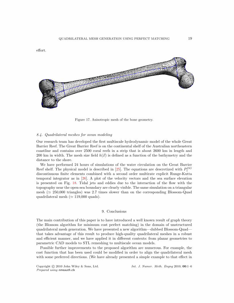
8.3. Quadrilateral mesh generation applied to parametric CAD models
We consider the solid model of a human bone. The model contains 11 NURBS surfaces. Themesh size field is based on surface curvature: we use formula (9) with Np = 35. The total timefor surface meshing was 26 seconds for generating 10, 134 quadrilateral elements. The time forcomputing all 11 perfect matchings and doing optimization does not exceed 10 seconds. Theaverage quality of the finite element mesh is η = 73.3% and the efficiency is τ = 80.2%. Themodel still contains 1 element of bad quality, with η = 0.01 (see Fig. 16).
Gmsh allows direct access to the CAD model, allowing to compute exactly the principaldirections of curvature together with minimal and maximal curvature. This allows to define an
Copyright c© 2010 John Wiley & Sons, Ltd. Int. J. Numer. Meth. Engng 2010; 00:1–6Prepared using nmeauth.cls

18 J.-F. REMACLE ET AL.
Figure 15. Quality histograms (element quality η (3) and normalized edge length lh (1)) for theBlossom-Quad remeshing of the bunny and the aneurysm models.
Bone
0.005
0.01
0.015
0.02
0.025
0.03
0.035
0 0.2 0.4 0.6 0.8 1
Fre
quen
cy
Element quality
0
Figure 16. Isotropic quad mesh of the bone geometry with a quality plot.
anisotropic mesh size field [7]. Here, we use formula (9) with Np = 35 in each of the directionsof principal curvature. An anisotropic triangular mesh is initially built using the anisotropicmetric provided by the curvature. Then, the Blossom-Quad algorithm is applied as it. Theresulting mesh is presented in Fig. 17. The quadrilateral mesh naturally aligns itself to theprincipal directions of curvature, allowing to build an anisotropic quadrilateral mesh without
Copyright c© 2010 John Wiley & Sons, Ltd. Int. J. Numer. Meth. Engng 2010; 00:1–6Prepared using nmeauth.cls
QUADRILATERAL MESH GENERATION USING PERFECT MATCHING 19
effort.
Figure 17. Anisotropic mesh of the bone geometry.
8.4. Quadrilateral meshes for ocean modeling
Our research team has developed the first multiscale hydrodynamic model of the whole GreatBarrier Reef. The Great Barrier Reef is on the continental shelf of the Australian northeasterncoastline and contains over 2500 coral reefs in a strip that is about 2600 km in length and200 km in width. The mesh size field h(~x) is defined as a function of the bathymetry and thedistance to the shore.
We have performed 24 hours of simulations of the water circulation on the Great BarrierReef shelf. The physical model is described in [25]. The equations are descretized with PDG
1
discontinuous finite elements combined with a second order multirate explicit Runge-Kuttatemporal integrator as in [26]. A plot of the velocity vectors and the sea surface elevationis presented on Fig. 18. Tidal jets and eddies due to the interaction of the flow with thetopography near the open-sea boundary are clearly visible. The same simulation on a triangularmesh (' 250,000 triangles) was 2.7 times slower than on the corresponding Blossom-Quadquadrilateral mesh (' 119,000 quads).
9. Conclusions
The main contribution of this paper is to have introduced a well known result of graph theory(the Blossom algorithm for minimum cost perfect matching) in the domain of unstructuredquadrilateral mesh generation. We have presented a new algorithm—dubbed Blossom-Quad—that takes advantage of this result to produce high-quality quadrilateral meshes in a robustand efficient manner, and we have applied it in different contexts: from planar geometries toparametric CAD models to STL remeshing to multiscale ocean models.
Possible further improvements to the proposed algorithm are numerous. For example, thecost function that has been used could be modified in order to align the quadrilateral meshwith some preferred directions. (We have already presented a simple example to that effect in
Copyright c© 2010 John Wiley & Sons, Ltd. Int. J. Numer. Meth. Engng 2010; 00:1–6Prepared using nmeauth.cls

20 J.-F. REMACLE ET AL.
Sea Surface Elevation and Velocity
Figure 18. Quadrilateral mesh of the Great Barrier Reef. Two successive zooms of the WithsundaysInslands Archipelago. Sea surface elevation (color levels) and bidimensional velocity field (arrows).
Copyright c© 2010 John Wiley & Sons, Ltd. Int. J. Numer. Meth. Engng 2010; 00:1–6Prepared using nmeauth.cls

QUADRILATERAL MESH GENERATION USING PERFECT MATCHING 21
Figure 19. Blossom-Quad algorithm applied to a triangular surface mesh that has been smoothedusing the Lp centroidal Voronoı tesselation technique of [24].
§4.3.) Also, in this paper we have used as input to the recombination procedure triangulationswith vertices distributed fairly uniformly. Recent developments [24, 27] allow to align thosevertices with some prescribed directions. Coupling both approaches could potentially leadto even higher quality quadrilateral meshes. As an example, we have applied the Blossom-Quad algorithm (without optimization) to a triangular surface mesh that has been smoothedusing the Lp centroidal Voronoı tesselation technique of [24]. The resulting mesh is presentedon Fig. 19. There, quadrangles do not form patches that are randomly aligned but follow aregular pattern.
In the longer run, the very challenging problem of automatic generation of hexahedral-dominant meshes could be approached using an indirect technique of this kind. In this case,more than two tetrahedra have to be merged in order to form one hexahedron. Here again, wethink that graph theory could maybe help us in finding some kind of optimal matching.
Acknowledgements
This work has been partially supported by the Belgian Walloon Region under WIST grantsONELAB 1017086 and DOMHEX 1017074.
Authors gratefully thanks F. Glineur and J. Hendricks from the Applied Math. Departmentof the Universite catholique de Louvain for the discussions and hints about graph theory.
Authors also acknowledge P. Frey of Universite Paris VI for authorizing us to include oneof the illustrations of his paper [3] (Fig. 13, top left).
Copyright c© 2010 John Wiley & Sons, Ltd. Int. J. Numer. Meth. Engng 2010; 00:1–6Prepared using nmeauth.cls

22 J.-F. REMACLE ET AL.
Authors finally deeply acknowledge B. Levy of LORIA Nancy for providing us with thetriangulation and the smoothing algorithm used to produce Fig. 19.
REFERENCES
1. Blacker TD, Stephenson MB. Paving: A new approach to automated quadrilateral mesh generation.International Journal for Numerical Methods in Engineering 1991; 32:811–847.
2. Lee CK, Lo SH. A new scheme for the generation of a graded quadrilateral mesh. Computers and Structures1994; 52:847–857.
3. Borouchaki H, Frey P. Adaptive triangular–quadrilateral mesh generation. International Journal forNumerical Methods in Engineering 1998; 45(5):915–934.
4. Owen SJ, Staten ML, Canann SA, Saigal S. Q-morph: An indirect approach to advancing front quadmeshing. International Journal for Numerical Methods in Engineering 1999; 9:1317–1340.
5. Edmonds J. Maximum matching and a polyhedron with 0-1 vertices. J. of Research at the National Bureauof Standards 1965; 69B(125–130).
6. Edmonds J, Johnson EL, Lockhart SC. Blossom I: A computer code for the matching problem. IBM T.J. Watson J. Edmonds, E. L. Johnson, and S. C. Lockhart. IBM T. IBM T.J. Watson Research Center,Yorktown Heights, New York 1969.
7. Frey P, George PL. Mesh Generation - Application To Finite Elements. Wiley, 2008.8. Edmonds J. Paths, trees, and flowers. Canad. J. Math 1965; 17:449–467.9. Lawler EL. Combinatorial Optimization: Networks and Matroids. Holt, Rinehart, and Winston, New York,
NY, 1976.10. Gabow H. Implementation of algorithms for maximum matching on nonbipartite graphs. PhD Thesis,
Stanford University 1973.11. Gabow H, Galil Z, Micali S. An o(ev log v) algorithm for finding a maximal weighted matching in general
graphs. SIAM J. Computing, 1986; 15(120–130).12. Gabow HN. Data structures for weighted matching and nearest common ancestors with linking. In
Proceedings of the 1st Annual ACM-SIAM Symposium on Discrete Algorithms,, 434-443 (ed.), 1990.13. Cook W, Rohe A. Computing minimum-weight perfect matchings. INFORMS Journal on Computing,
1999; 11(2)(138–148).14. Geuzaine C, Remacle JF. Gmsh: a three-dimensional finite element mesh generator with built-in pre- and
post-processing facilities. International Journal for Numerical Methods in Engineering 2009; 79(11):1309–1331.
15. Bommes D, Zimmer H, Kobbelt L. Mixed-integer quadrangulation. SIGGRAPH ’09: ACM SIGGRAPH2009 papers, ACM: New York, NY, USA, 2009; 1–10, doi:http://doi.acm.org/10.1145/1576246.1531383.
16. Tutte WT. A family of cubical graphs. Proc. Cambridge Philos. Soc. 1947; 43:459–474.17. Pemmaraju S, Skiena S. Computational Discrete Mathematics: Combinatorics and Graph Theory with
Mathematica R©. Cambridge University Press: New York, NY, USA, 2003.18. Kasteleyn PW. Dimer Statistics and Phase Transitions. Journal of Mathematical Physics Feb 1963; 4:287–
293, doi:10.1063/1.1703953.19. Oum S. Perfect Matchings in Claw-free Cubic Graphs. ArXiv e-prints Jun 2009; .20. Sarrate J, Huerta A. An improved algorithm to smooth graded quadrilateral meshes preserving the
prescribed element size. Communications in numerical methods in engineering 2001; 17(2):89–99.21. Daniels J II, Silva CT, Cohen E. Localized quadrilateral coarsening. SGP ’09: Proceedings of the
Symposium on Geometry Processing, Eurographics Association: Aire-la-Ville, Switzerland, Switzerland,2009; 1437–1444.
22. Marchandise E, de Wiart C, Vos W, Geuzaine C, Remacle J. High-quality surface remeshing using harmonicmaps–part ii: Surfaces with high genus and of large aspect ratio. International Journal for NumericalMethods in Engineering 2011; 86:1303–1321.
23. Guennebaud G, Germann M, Gross M. Dynamic sampling and rendering of algebraic point set surfaces.Computer Graphics Forum 2008; 27:653–662.
24. Levy B, Liu Y. Lp centroidal voronoi tesselation and its applications. ACM Transactions on Graphics(SIGGRAPH conference proceedings), 2010.
25. Lambrechts J, Hanert E, Deleersnijder E, Bernard PE, Legat V, Wolanski JFRE. A high-resolution modelof the whole great barrier reef hydrodynamics. Estuarine, Coastal and Shelf Science 2008; 79(1):143–151.Doi 10.1016/j.ecss.2008.03.016.
26. Constantinescu EM, Sandu A. Multirate timestepping methods for hyperbolic conservation laws. Journalof Scientific Computing 2007; 33:239–278, doi:10.1007/s10915-007-9151-y.
Copyright c© 2010 John Wiley & Sons, Ltd. Int. J. Numer. Meth. Engng 2010; 00:1–6Prepared using nmeauth.cls

QUADRILATERAL MESH GENERATION USING PERFECT MATCHING 23
27. Hausner A. Simulating decorative mosaics. Proceedings of the 28th annual conference on Computergraphics and interactive techniques, ACM, 2001; 573–580.
Copyright c© 2010 John Wiley & Sons, Ltd. Int. J. Numer. Meth. Engng 2010; 00:1–6Prepared using nmeauth.cls