blancco 5 · b5ct blancco 5 configuration tool. blancco software used to configure the blancco 5...
TRANSCRIPT

www.blancco.com
BLANCCO 5
User Manual for version 5.5.1

2/65
DEFINITIONS
ITEM EXPLANATION
4.x, 5.x... This is the version numbering. The sentence “compatible with 4.x” means that it is
compatible with the Erasure client version 4.0, 4.1, 4.2 and so on.
ATA, PATA Short for Advanced Technology Attachment (ATA) and Parallel ATA. These are
interface standards for the connection of storage devices such as HDDs.
B5CT Blancco 5 Configuration Tool. Blancco software used to configure the Blancco 5
ISO image to best fit the user’s needs. Please read the B5CT manual for more
information.
BIOS Acronym for Basic Input/Output System. On PCs, BIOS contains all the code
required to control, for example, the keyboard, display screen and disk drives.
BMC Blancco Management Console. Blancco software used to store and manage Blancco
erasure reports. Please read the BMC manual for more information.
Checksum A checksum or hash sum is a fixed-size datum computed from an arbitrary block of
digital data for the purpose of detecting accidental errors that may have been
introduced during its transmission or storage.
DCO Device Configuration Overlay allows system vendors to purchase data storage
devices from different manufacturers with potentially different sizes, and then
configures all devices to have the same number of sectors.
FEPROM A rewritable memory chip that holds its content without power. Flash Erasable
Programmable Read-Only Memory or "flash memory" is a kind of non-volatile
storage device where erasing can only be done in blocks or the entire chip.
Fibre Channel A serial data transfer architecture. The most prominent Fibre Channel standard is
Fibre Channel Arbitrated Loop (FC-AL).
Firmware In electronic systems and computing, firmware is the combination of persistent
memory and program code and data stored in it.
Firmware based
erasure
A way of erasing a data storage device (HDD, SSD) using internal commands
(located in the device firmware). The erasure commands can differ depending on
the drive interface (ATA, SCSI, SAS, SATA…).
Freeze lock Some BIOS versions offer the ability to lock ATA drives: the access, creation or
removal of HPAs/DCOs or the use of commands in Security and Sanitize Device-
feature sets to erase the drive are blocked. These locks are called “freeze locks”.
When the freeze lock is enabled for some feature set, its commands cannot be
processed. These locks prevent external software from creating/modifying/
removing HPA or DCO areas, erasing reallocated sectors or performing firmware
based erasures.
HASP Short for Hardware Against Software Piracy, it is a software protection dongle that
plugs into an electrical connector on a computer and serves as an electronic “key”
for a piece of software. The program will run only when the dongle is plugged in.
HBA Host Bus Adapter connects a host system to other network and storage devices.
HDD Hard Disk Drive is a data storage device used for storing digital information using
rapidly rotating discs with magnetic surfaces.
Hexviewer A Hexviewer is a type of computer program that allows a user to access binary
computer files. Blancco Hexviewer allows the user to read the binary content of a
drive before or after its erasure.

3/65
HPA The Host Protected Area (HPA) as defined is a reserved area on a data storage
device. It was designed to store information in such a way that it cannot be easily
modified, changed, or accessed by the user, BIOS, or the OS.
IDE Integrated Drive Electronics is an interface for mass storage devices, in which the
controller is integrated into the disk or CD-ROM drive. Although it really refers to a
general technology, the term to usually refers to the ATA specification, which uses
this technology.
ISO image An ISO image is an archive file of an optical disc, a type of disk image, composed
of the data contents of every written sector of an optical disc, including the optical
disc file system.
LAN A local area network (LAN) is a computer network that interconnects computers in
a limited area.
LUN Logical Unit Number is the identifier of a SCSI logical unit, and by extension of a
Fibre Channel or iSCSI logical unit. A logical unit is a SCSI protocol entity which
performs classic storage operations such as ‘read’ and ‘write’.
OS Operating System or OS is a set of software that manages computer hardware
resources and provides common services for computer programs. It is a vital
component of the system software; programs require an OS to function.
PXE The Preboot eXecution Environment is an environment to boot computers using a
network interface independently of data storage devices or installed operating
systems.
RAID Redundant Array of Independent Disks is a technology that provides increased
storage reliability through redundancy, combining multiple disk drive components
into a logical unit where all drives in the array are interdependent.
Remapped/Reallocated
Sectors
Count of reallocated sectors. When the drive finds a read/write/verification error, it
marks this sector as "reallocated" and transfers data to a special reserved area
(spare area).
SAS Short for Serial Attached SCSI, it is a communication protocol used to move data to
and from computer storage devices such as hard drives and tape drives. SAS is a
point-to-point serial protocol that replaces the parallel SCSI bus technology.
SATA Serial ATA or SATA is an evolution of the Parallel ATA physical storage interface.
SATA is a serial link – a single cable with a minimum of four wires creates a point-
to-point connection between devices.
SCSI Short for Small Computer System Interface, a parallel interface standard used by
Apple Macintosh computers, PCs, and many UNIX systems for attaching peripheral
devices to computers.
SPI In Blancco 5, SPI stands for SCSI Parallel Interface, the predecessor of SAS. It is
one of the interface implementations in the SCSI family and it defines the electrical
signals and connections for parallel SCSI.
SSD Solid State Drive is a data storage device used for storing digital information using
integrated circuit assemblies as memory to store data persistently.
SSID SSID stands for "Service Set Identifier”. An SSID is a unique ID that consists of 32
characters and is used for naming wireless networks. When multiple wireless
networks overlap in a certain location, SSIDs make sure that the data gets sent to
the correct destination.
UEFI/EFI Unified Extensible Firmware Interface (UEFI) is a specification that defines a
software interface between an operating system and platform firmware. UEFI is
4/65
meant to replace the Basic Input/Output System (BIOS) firmware interface,
present in all IBM PC-compatible personal computers.
UI, GUI Short for User Interface and Graphical User Interface.
WLAN Wireless LAN, a local area network that uses high frequency radio signals rather
than cables to transmit and receive data over distances of a few hundred feet
wirelessly.
5/65
TABLE OF CONTENTS
1 General information ...............................................................................................9
1.1 Legal Notice ................................................................................................. 10
2 Blancco 5 User Interface ....................................................................................... 12
2.1 Header area ................................................................................................. 12
2.2 Process area ................................................................................................ 12
2.3 Work area ................................................................................................... 12
2.4 Color codes.................................................................................................. 13
2.4.1 Gray color.............................................................................................. 13
2.4.2 Green color ............................................................................................ 13
2.4.3 Yellow color ........................................................................................... 13
2.4.4 Red color............................................................................................... 13
2.4.5 Blue color .............................................................................................. 13
3 Header area ....................................................................................................... 14
3.1 Software version and license control .................................................................. 14
3.2 “Hexviewer” function button ............................................................................ 14
3.3 “Settings” function button ............................................................................... 16
3.4 “Report Issue” function button ......................................................................... 17
3.5 “Help” function button.................................................................................... 18
3.6 “Shutdown” function button............................................................................. 19
4 Process and Work areas........................................................................................ 20
4.1 Processes .................................................................................................... 20
4.1.1 Manual.................................................................................................. 20
4.1.2 Semi-automatic....................................................................................... 20
4.1.3 Automatic .............................................................................................. 20
4.2 “Erasure”-step .............................................................................................. 21
4.2.1 Tab color and overall progress.................................................................... 21
4.2.2 Remaining time and state icon ................................................................... 22
4.2.3 Work area ............................................................................................. 23
4.2.3.1 Standard view................................................................................... 23
4.2.3.1.1 Erase-button.................................................................................. 24
6/65
4.2.3.1.2 Drive’s progress bar ........................................................................ 25
4.2.3.2 Advanced view.................................................................................. 26
4.2.3.2.1 Erasure standards ........................................................................... 27
4.2.3.2.2 Erase remapped sectors ................................................................... 28
4.2.3.2.3 Verification .................................................................................... 28
4.2.3.2.4 Erase-button.................................................................................. 28
4.2.3.2.5 Drive’s progress bar ........................................................................ 29
4.2.3.2.6 Drive info-icons .............................................................................. 31
4.3 “Input & edit”-step ........................................................................................ 32
4.3.1 Tab color and overall progress.................................................................... 32
4.3.2 Work area ............................................................................................. 32
4.3.2.1 Customer & Operator information.......................................................... 33
4.3.2.2 Custom fields.................................................................................... 33
4.3.2.3 Update-button .................................................................................. 34
4.4 “Report”-step ............................................................................................... 35
4.4.1 Tab color and overall progress.................................................................... 35
4.4.2 Work area ............................................................................................. 36
4.4.2.1 Report content .................................................................................. 36
4.4.2.2 Save-button ..................................................................................... 36
4.4.2.3 Send-button ..................................................................................... 38
4.5 Small asset report ......................................................................................... 39
5 Keyboard Controls ............................................................................................... 40
5.1 Generic controls ............................................................................................ 40
5.1.1 Tab key................................................................................................. 40
5.1.2 Arrow keys ............................................................................................ 40
5.1.3 Space bar .............................................................................................. 40
5.1.4 Enter key............................................................................................... 40
5.1.5 Escape key ............................................................................................ 41
5.2 Accessing the Header area .............................................................................. 41
5.2.1 F1-F4 function keys ................................................................................. 41
5.2.2 F10 function key ..................................................................................... 41
5.3 Accessing the Process area.............................................................................. 41
5.4 Navigation inside the Work area ....................................................................... 41

7/65
5.4.1 Erasure-step .......................................................................................... 41
5.4.1.1 Ctrl + M .......................................................................................... 42
5.4.1.2 Ctrl + E ........................................................................................... 42
5.4.1.3 Ctrl + A ........................................................................................... 42
5.4.2 Input&edit-step....................................................................................... 42
5.4.3 Report-step............................................................................................ 42
6 Screensaver ....................................................................................................... 43
7 Blancco 5 Security features ................................................................................... 44
7.1 Booting Options ............................................................................................ 44
7.1.1 Description ............................................................................................ 44
7.1.2 When to use the booting options? ............................................................... 44
7.2 Software version ........................................................................................... 45
7.3 Detecting HDDs ............................................................................................ 45
7.4 Bad sector (read/write error) handling ............................................................... 45
7.5 Remapped sectors ......................................................................................... 46
7.6 Freeze lock .................................................................................................. 46
7.7 Hidden areas in a drive................................................................................... 47
7.7.1 Host Protected Area (HPA) ........................................................................ 47
7.7.2 Device Configuration Overlay (DCO) ............................................................ 47
7.8 Erasure verification ........................................................................................ 48
7.9 Digital Fingerprint.......................................................................................... 48
7.10 Hardware not supported by Blancco 5 ................................................................ 49
7.10.1 Unsupported processors............................................................................ 49
7.10.1 Unsupported drives.................................................................................. 49
7.10.2 SSDs .................................................................................................... 50
7.10.3 RAID-controllers...................................................................................... 50
8 Troubleshooting .................................................................................................. 51
8.1 Burning the *.iso image / Creating the CD .......................................................... 51
8.2 Accessing the BIOS and changing the boot sequence ............................................ 51
8.3 Booting on machines with UEFI ........................................................................ 52
8.3.1 Disabling the Secure Boot ......................................................................... 52
8.3.1.1 General steps ................................................................................... 52
8.3.1.2 Windows Surface Pro.......................................................................... 52
8/65
8.3.2 Booting with a Blancco 5 USB-stick .............................................................. 53
8.4 Blancco 5 hangs during the booting................................................................... 53
8.5 Booting without a display adapter ..................................................................... 53
8.6 SATA drives not detected/not available in the User interface ................................... 54
8.7 Problems with the Freeze lock removal............................................................... 54
8.8 HP Smart Array erasure .................................................................................. 55
9 Appendix 1: SSD supplement ................................................................................. 57
9.1 Guidelines for Using SSD Erasure Method ........................................................... 57
9.2 Erasure Result .............................................................................................. 57
9.2.1 Status ................................................................................................... 57
9.2.2 Failure Logic........................................................................................... 57
9.3 Handling Information ..................................................................................... 58
9.3.1 Erasure Method ...................................................................................... 58
9.3.2 Inoperable Drives .................................................................................... 59
9.3.3 Failed Erasures ....................................................................................... 59
10 Appendix 2: Execution steps of the erasure standards .............................................. 61
10.1 Magnetic standards ....................................................................................... 61
10.2 Firmware and forced standards ........................................................................ 63
10.3 SSD Standards ............................................................................................. 64
11 Contact Information.......................................................................................... 65
9/65
1 GENERAL INFORMATION
This manual is written for the Blancco 5 family for x86 based computer architectures.
PLEASE CAREFULLY READ THE NEXT PARAGRAPH BEFORE YOU START USING THE
PROGRAM
Thank you for choosing Blancco for your data erasure needs. Before you start using the Blancco
Erasure software make sure that all files, folders, software applications or any other information
that you want to save for later use are backed up on an appropriate media device other than the
original data storage device (HDD, SSD). If you are not sure whether to erase the information on
the drive, please contact your system operator, information management or a corresponding
party, which maintains the computers in your organization. For future use of the erased computer,
an operating system must be installed. Data that has been erased from a data storage device with
this program cannot be recovered by any existing method.
Minimum System Requirements
x86 architecture machine
512 MB RAM memory in most cases, erasing servers with 4+ drives requires more RAM
CD-drive or a CD-compatible drive
USB-port for exporting / saving reports locally
SVGA display and VESA compatible video card for graphical user interface
[Optional] Ethernet NIC, DHCP Server running on local network
Blancco 5 can also be booted from a USB flash drive. A bootable USB flash drive can be created
with the help of Blancco USB Creator tool. Contact Blancco for more information.
If there is a dedicated network for erasing machines, Blancco 5 can also boot via a Preboot
eXecution Environment or PXE (as long as the machines to be erased support PXE booting).
Contact Blancco for more information.
After Blancco 5.5.1 has finished booting, any optical media drive detected on the machine will be
opened (tray eject). This will happen even if booting has been done from a USB flash drive or
through the network.
This way the user can check if a Blancco 5 boot CD or any other optical media has been left in the
machine. This also prevents the risk of forgetting to remove media from a machine before shipping
it away, since this presents a security risk as these media may contain personal/professional
information.
Requirements for the User
Person(s) using this program should have prior experience using computers and the user should,
at all times, follow the guidance of this documentation and all guidance given by Blancco.
Booting and Computer Settings
10/65
Check that all the drives are attached properly to the computer. See the manufacturer’s
guide for this.
Check that the BIOS clock’s time is up to date.
If you have a laptop computer, plug in the power adapter. There may be problems when
erasing a laptop on battery power.
Disable or type the BIOS passwords requested during the booting up phase. This refers to
the passwords that some computers require even before the actual booting starts. Other
kinds of BIOS passwords do not usually prevent erasing the drive.
Disable power saving features from the BIOS.
Note. This step is usually not needed, but some hardware may have problems if power
saving is enabled, so if you have just one license, it is prudent to do this. In a recycling
center or corporate environment this should be done only if there are problems with the
given computer model when the power saving is on.
If your Blancco 5 software is in *.iso image form, burn it to a CD or make a bootable USB-
stick.
Switch-on the computer power, put in the Blancco 5 CD and boot the system from the CD
(or use the booting that suits you best). Read the section “Accessing the BIOS and
changing the boot sequence” for further info.
Follow the user instructions in order to start erasing the data. Double-check that all data
storage devices have been detected correctly so that all the data will be correctly erased
from them.
Note. Blancco provides the MD5 checksum of the ISO image in the delivery email. To verify that
the MD5-checksum for your image is correct, please use a MD5 checksum verification tool.
Warning! Shutting the computer down, exiting the program, disconnecting the drive(s) or
pausing/cancelling the process when Blancco 5 is performing an erasure on the drive(s) with NIST
800-88 Purge - ATA, BSI-GS/E, (Extended) Firmware based erasure or Blancco SSD Erasure, can
permanently damage the drive(s). This also applies to any erasure with the “Erase remapped
sectors” option checked.
Note. In a general way, you should avoid shutting down the computer, exiting the program or
disconnecting any drive while erasing it with any standard. This is because all erasure information
will be lost and the drive may result damaged.
1.1 Legal Notice
Notwithstanding the foregoing, Blancco shall bear no responsibility for any interference,
operability, or other compatibility issues which may arise as a result of any changes or updates
made to the operating systems and/or hardware upon which the Blancco Software is executed.
Likewise, Blancco shall be in no way responsible for any interference, operability, or any other
issues resulting from infection of systems and hardware upon which the Blancco Software is
executed by any form of virus, Trojan Horse, worm, malware, or spyware of any form or type
(collectively referred to hereafter as “Virus” of “Viruses”). The sole responsibility for maintaining a
Virus free environment for the operation of the Blancco Software or Hardware solutions shall rest
solely with the Company.
11/65
The license to the Product is non-transferable and is granted personally to the Licensee, and the
Licensee shall not, without prior written consent of Blancco, be entitled to assign or transfer the
license for any reason including, without limitation, merger, reorganization, sale of all or
substantially all of the assets, change of control or operation of law.
12/65
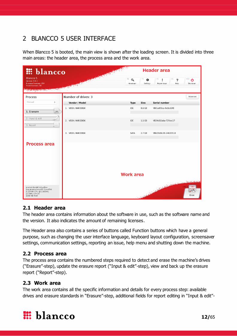
2 BLANCCO 5 USER INTERFACE
When Blancco 5 is booted, the main view is shown after the loading screen. It is divided into three
main areas: the header area, the process area and the work area.
2.1 Header area
The header area contains information about the software in use, such as the software name and
the version. It also indicates the amount of remaining licenses.
The Header area also contains a series of buttons called Function buttons which have a general
purpose, such as changing the user interface language, keyboard layout configuration, screensaver
settings, communication settings, reporting an issue, help menu and shutting down the machine.
2.2 Process area
The process area contains the numbered steps required to detect and erase the machine’s drives
(“Erasure”-step), update the erasure report (“Input & edit”-step), view and back up the erasure
report (“Report”-step).
2.3 Work area
The work area contains all the specific information and details for every process step: available
drives and erasure standards in “Erasure”-step, additional fields for report editing in “Input & edit”-
13/65
step, asset and erasure information in “Report”-step. Moreover, the user can switch between a
Standard and an Advanced view of the UI while performing a drive erasure.
Most of the actions of the user and interaction with the software take place in the Work area.
2.4 Color codes
Several colors are used in the Blancco UI. These colors allow a clear understanding of the current
status of an action being carried out.
2.4.1 Gray color
Task has not yet been initialized or is not active.
2.4.2 Green color
The task has been completed successfully. E.g. selected drive erased successfully, additional
report fields updated successfully and report sent/saved successfully.
2.4.3 Yellow color
User action is required. E.g. drive erasure is paused (requires user intervention). Also, if an
erasure raises a warning, a “yellow” informative message is written in the report.
2.4.4 Red color
Given task has failed. E.g. drive erasure process has failed or has been cancelled, input is
mandatory but nothing has been written in the input-field or report sending/saving has failed.
2.4.5 Blue color
Process or given task is running. E.g. drive erasure process is running, ongoing erasures additional
fields are being updated or sending/saving report is still in progress.

14/65
3 HEADER AREA
3.1 Software version and license control
Blancco 5 software version is located on the top left of the screen, under the logo. Information
about the amount of remaining licenses is displayed below the software version number:
Blancco 5 has two different license types:
- Erasure licenses: these licenses are necessary to erase drives. Consuming one erasure
license allows the user to save/send reports.
- Asset licenses: in case there are no Erasure licenses (or if the user hasn’t erased any
drive), these licenses are necessary to save or send a report with all the hardware
information of the machine (asset report).
Blancco 5 license control is done either from a local HASP dongle, or from the BMC via the
network. There must be enough licenses in order to start the erasure or save/send an
asset report.
If the license container cannot be reached, the following messages will be displayed:
3.2 “Hexviewer” function button
The Hexviewer is used to check the content of a storage media in hexadecimal format. Whenever
a drive is overwritten with Blancco 5, a pattern (either static or random) is used to overwrite it: the
hex-format of this pattern (e.g. 0x00, 0xAA, 0x924924…) can be viewed with the Hexviewer thus
providing a visual verification of the performed erasure result.

15/65
Name Example Description
Drive and sector
Select drive:
1 VBOX HARDDISK
(8.6GB) Vbed6ccd6e
Dropdown-list displaying all detected drives, used to
select the storage media to hex-view. Each drive is
identified with its number, vendor and model,
capacity and serial number.
Select sector:
100 / 204799
Sector being viewed currently, displayed against the
total amount of sectors of the drive. Typing a sector
number and pressing the Enter-key will show the
sector in question. Note that the first sector is
numbered 0 i.e. a drive with 100 sectors will have
sectors in the range 0-99.
Hexadecimal data
Left column
48 69 21 00 AA
The left side of the Hexviewer displays the sector’s
data in hexadecimal format. If the sector size is 512
bytes, the left side will be a 32 x 16 matrix.
Right column
H i ! . .
The right side of the Hexviewer displays the
sector’s data in ASCII format. If the sector size is
512 bytes, the left side will be a 32 x 16 matrix.
Non-printable ASCII chars and non-ASCII chars are
represented by a dot (“.”).
Horizontal slider
-
Used to scroll through different sectors. Whenever
dragged with the mouse or moved with the Arrow
keys, it will jump several sectors forward/backward
(a jump equivalent to roughly 1% of the drive’s
total amount of sectors).
“First” button - Moves to and displays the first sector of the drive.

16/65
“Previous” button - Moves to and displays the previous sector.
“Next” button - Moves to and displays the next sector.
“Last” button - Moves to and displays the last sector of the drive.
The Hexviewer can also be used to read the Digital Fingerprint information, please check chapter
Digital Fingerprint for more information.
3.3 “Settings” function button
The Blancco 5 settings are accessed via the “Settings”-button.
Pressing the button opens the Settings-window. This window contains information related to the
User Interface and the BMC connectivity:
Name Example Description
User Interface settings
Language: English – en The language used in the software.
Keyboard Layout: English (United
States) - us
Keyboard layout used in the system.
Screensaver Settings
Enable screensaver On or Off Enable/disable the screensaver.
17/65
Timeout (sec.):
30
Timeout of the screensaver (in seconds), time of
inactivity before the screensaver is turned on.
Possible values: from 5 sec. to 86400 sec. (1 day).
Communication settings
Hostname / IP: 10.1.1.1 IP-address of the server running the BMC.
Port:
8443
Port number of the BMC. This port was set up when
installing the BMC; it is the port 8443 by default
(HTTPS protocol always enforced). Please check
the BMC manual for more information.
Username: ExampleMCUser User for accessing the BMC.
Password: VeryStrongPassword Password for accessing the BMC.
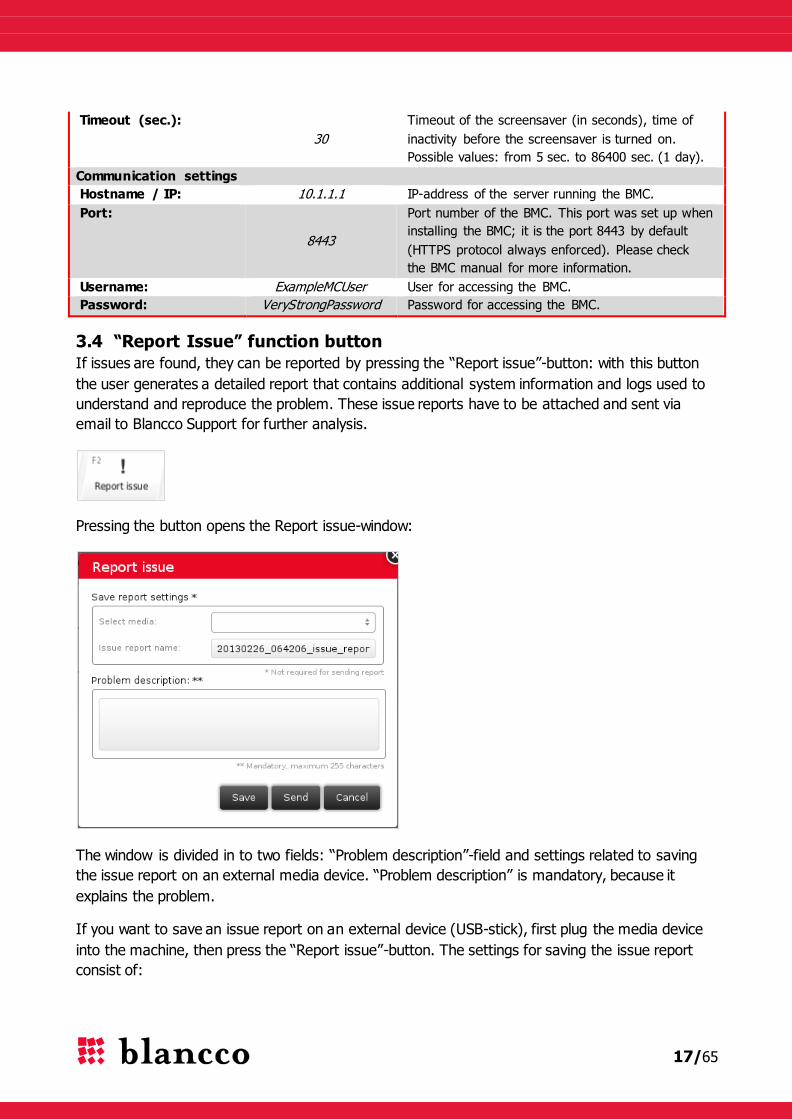
3.4 “Report Issue” function button
If issues are found, they can be reported by pressing the “Report issue”-button: with this button
the user generates a detailed report that contains additional system information and logs used to
understand and reproduce the problem. These issue reports have to be attached and sent via
email to Blancco Support for further analysis.
Pressing the button opens the Report issue-window:
The window is divided in to two fields: “Problem description”-field and settings related to saving
the issue report on an external media device. “Problem description” is mandatory, because it
explains the problem.
If you want to save an issue report on an external device (USB-stick), first plug the media device
into the machine, then press the “Report issue”-button. The settings for saving the issue report
consist of:

18/65
- “Select media”-dropdown menu, and select the appropriate media device (USB-stick) to
save the issue report.
- “Issue Report Name”-field, which defines the file name of the report. The default name of
the report follows the format: Date(yyyymmdd)_time(hh24miss)_issue_report
o A report named “20121205_164206_issue_report” was created 5th of December,
2012 at 4:42:06 PM.
o This name can eventually be changed before saving the issue report to the external
media.
- The only available file format is XML (it will automatically be added to the issue report
name).
- “Save”-button, press this button to save the issue report on your external device (USB-
stick).
The other available buttons in the window are:
- “Send”-button, for sending the issue report to the BMC. This requires:
o a network connection and a server running the BMC,
o correct Communication settings filled in the “Settings”-window.
- “Cancel”-button, to cancel the issue report generation and exit the window.
3.5 “Help” function button
The “Help”-button is used to open the quick-help menu.
Pressing this button opens the Help-window. This window contains information about the GUI
(Graphical User Interface), header area, process and working areas, keyboard control of Blancco 5
and also a quick guide for performing erasures.
The Help window consists of two columns:
- the left column contains the Help table of contents as well as a search box,
- the right column contains the Help content, selecting a chapter in the table of contents will
automatically update the content.
19/65
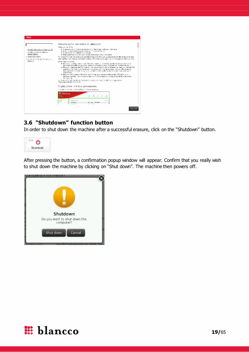
3.6 “Shutdown” function button
In order to shut down the machine after a successful erasure, click on the “Shutdown” button.
After pressing the button, a confirmation popup window will appear. Confirm that you really wish
to shut down the machine by clicking on “Shut down”. The machine then powers off.
20/65
4 PROCESS AND WORK AREAS
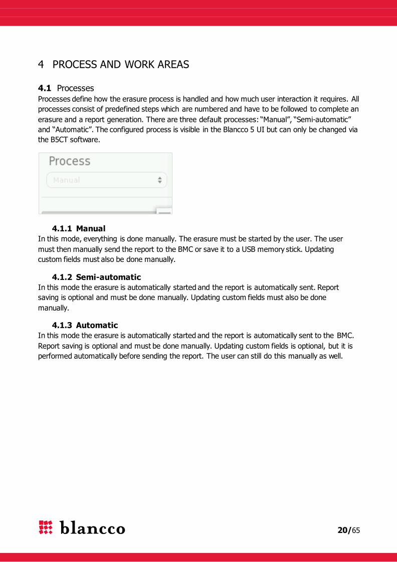
4.1 Processes
Processes define how the erasure process is handled and how much user interaction it requires. All
processes consist of predefined steps which are numbered and have to be followed to complete an
erasure and a report generation. There are three default processes: “Manual”, “Semi-automatic”
and “Automatic”. The configured process is visible in the Blancco 5 UI but can only be changed via
the B5CT software.
4.1.1 Manual
In this mode, everything is done manually. The erasure must be started by the user. The user
must then manually send the report to the BMC or save it to a USB memory stick. Updating
custom fields must also be done manually.
4.1.2 Semi-automatic
In this mode the erasure is automatically started and the report is automatically sent. Report
saving is optional and must be done manually. Updating custom fields must also be done
manually.
4.1.3 Automatic
In this mode the erasure is automatically started and the report is automatically sent to the BMC.
Report saving is optional and must be done manually. Updating custom fields is optional, but it is
performed automatically before sending the report. The user can still do this manually as well.

21/65
4.2 “Erasure”-step
The “Erasure”-step is the first defined default step. When clicking on this step, the user can see in
the work area the drives available for erasure. The erasure step’s tab also shows some information
about the erasures’ overall process.
4.2.1 Tab color and overall progress
The “Erasure”-step tab’s color informs of the overall erasure progress: not started (gray), ongoing
(blue), successful (green), failed or canceled (red), paused (yellow). Whenever there is at least
one erasure ongoing, the erasure percentage is also displayed in the tab. Information about the
number of drives being erased and their status is also written under the erasure tab.
Erasure tab – erasure not yet started
Erasure tab – ongoing erasure(s)
Erasure tab – successful erasure(s)
Erasure tab – failed erasure(s)
Erasure tab – canceled erasure(s)

22/65
Erasure tab – paused erasure(s)
4.2.2 Remaining time and state icon
Indication of the remaining erasure time is also displayed under the “Erasure” tab.
The following icons are shown under the “Erasure” tab when erasures are in different states:
All erasures have been successful.
At least one erasure was canceled by the user. This overrules the successful-icon.
At least one erasure has been paused by the user. This overrules the canceled-icon.
At least one erasure has failed. This overrules the paused-icon.
If there are multiple drives in different states, then the erasure-tab may look like the next picture:
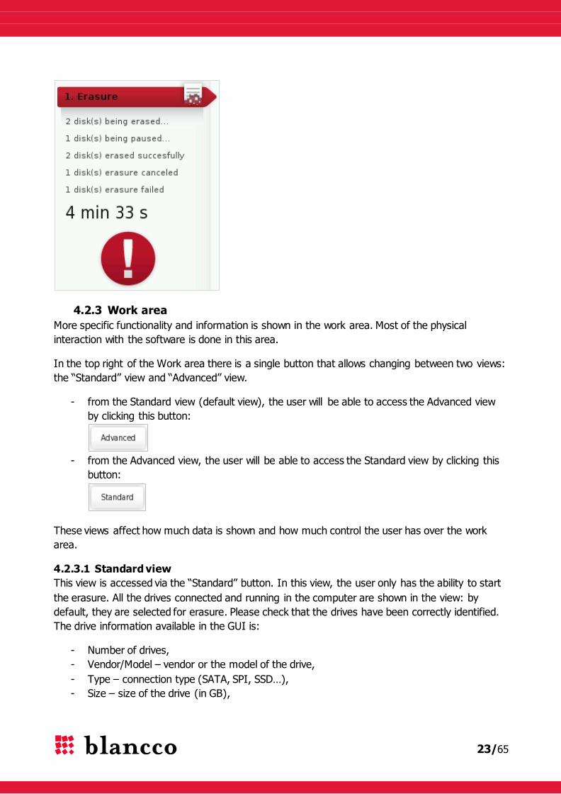
23/65
4.2.3 Work area
More specific functionality and information is shown in the work area. Most of the physical
interaction with the software is done in this area.
In the top right of the Work area there is a single button that allows changing between two views:
the “Standard” view and “Advanced” view.
- from the Standard view (default view), the user will be able to access the Advanced view
by clicking this button:
- from the Advanced view, the user will be able to access the Standard view by clicking this
button:
These views affect how much data is shown and how much control the user has over the work
area.
4.2.3.1 Standard view
This view is accessed via the “Standard” button. In this view, the user only has the ability to start
the erasure. All the drives connected and running in the computer are shown in the view: by
default, they are selected for erasure. Please check that the drives have been correctly identified.
The drive information available in the GUI is:
- Number of drives,
- Vendor/Model – vendor or the model of the drive,
- Type – connection type (SATA, SPI, SSD…),
- Size – size of the drive (in GB),

24/65
- Serial number – serial number of the drive.
4.2.3.1.1 Erase-button
In order to start the erasure, the user has to press the “Erase” button, which is located on the
bottom right of the screen:
- The erasure method (or standard) used is always the default one, so is the verification
level and the remapped sectors erasure (all selected when configuring the ISO image with
the B5CT),
- The erasure of each drive can be monitored via the drive’s progress bar.
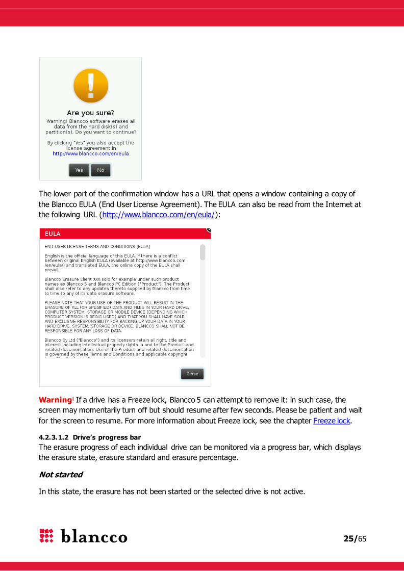
After the “Erase”-button is pressed the following confirmation window is shown. Pressing “Yes”
continues to the erasure. Pressing “No” exits the window and does not start the erasure.
25/65
The lower part of the confirmation window has a URL that opens a window containing a copy of
the Blancco EULA (End User License Agreement). The EULA can also be read from the Internet at
the following URL (http://www.blancco.com/en/eula/):
Warning! If a drive has a Freeze lock, Blancco 5 can attempt to remove it: in such case, the
screen may momentarily turn off but should resume after few seconds. Please be patient and wait
for the screen to resume. For more information about Freeze lock, see the chapter Freeze lock.
4.2.3.1.2 Drive’s progress bar
The erasure progress of each individual drive can be monitored via a progress bar, which displays
the erasure state, erasure standard and erasure percentage.
Not started
In this state, the erasure has not been started or the selected drive is not active.

26/65
Active/Ongoing
In this state, the erasure process is being performed. The progress is shown by the blue bar and
the percentage of completion. The erasure standard used for erasure is shown on the left side of
the progress bar.
Paused
In this state, the erasure has been paused. The erasure can be resumed by pressing the resume-
button or canceled by pressing the cancel-button (these buttons are only available in the
“Advanced” view).
Finished
When the erasure has been successfully completed, the progress bar looks like this:
Canceled
If the erasure has been canceled, the progress bar looks like this:
Failed
If the erasure has failed, the progress bar looks like this:
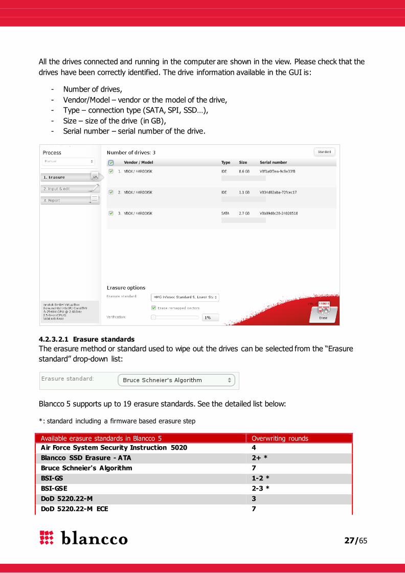
4.2.3.2 Advanced view
This view is accessed via the “Advanced” button. In this view the user can individually select or
group the drives for erasure. The erasure method (or standard) the user wants to use, whether or
not the remapped sectors are erased from the drive as well as the level of the verification (which
is done during or after the erasure) can also be defined individually or per group. By clicking
“Erase”, the software starts the erasure process for all of the selected drives. The progress bar and
time remaining indicator show how long it takes before the process completes.
27/65
All the drives connected and running in the computer are shown in the view. Please check that the
drives have been correctly identified. The drive information available in the GUI is:
- Number of drives,
- Vendor/Model – vendor or the model of the drive,
- Type – connection type (SATA, SPI, SSD…),
- Size – size of the drive (in GB),
- Serial number – serial number of the drive.
4.2.3.2.1 Erasure standards
The erasure method or standard used to wipe out the drives can be selected from the “Erasure
standard” drop-down list:
Blancco 5 supports up to 19 erasure standards. See the detailed list below:
*: standard including a firmware based erasure step
Available erasure standards in Blancco 5 Overwriting rounds
Air Force System Security Instruction 5020 4
Blancco SSD Erasure - ATA 2+ *
Bruce Schneier's Algorithm 7
BSI-GS 1-2 *
BSI-GSE 2-3 *
DoD 5220.22-M 3
DoD 5220.22-M ECE 7
28/65
NIST 800-88 Clear 1
NIST 800-88 Purge - ATA 0 *
Firmware based Erasure 0 *
Extended Firmware based Erasure 1 *
HMG Infosec Standard 5, Higher Standard 3
HMG Infosec Standard 5, Lower Standard 1
National Computer Security Center (NCSC-TG-025) 4
Navy Staff Office Publication (NAVSO P-5239-26) 3
NSA 130-1 3
OPNAVINST 5239.1A 3
Peter Gutmann's Algorithm 35
U.S. Army AR380-19 3
Erasure standards supported by Blancco 5. See the chapter Execution steps of the erasure
standards for more information
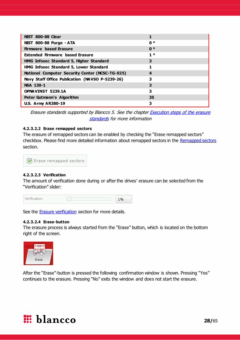
4.2.3.2.2 Erase remapped sectors
The erasure of remapped sectors can be enabled by checking the “Erase remapped sectors”
checkbox. Please find more detailed information about remapped sectors in the Remapped sectors
section.
4.2.3.2.3 Verification
The amount of verification done during or after the drives’ erasure can be selected from the
“Verification” slider:
See the Erasure verification section for more details.
4.2.3.2.4 Erase-button
The erasure process is always started from the “Erase” button, which is located on the bottom
right of the screen.
After the “Erase”-button is pressed the following confirmation window is shown. Pressing “Yes”
continues to the erasure. Pressing “No” exits the window and does not start the erasure.

29/65
The lower part of the confirmation window has a URL that opens a window containing a copy of
the Blancco EULA (End User License Agreement). The EULA can also be read from the Internet at
the following URL (http://www.blancco.com/en/eula/):
Warning! If a drive has a Freeze lock, Blancco 5 can attempt to remove it: in such case, the
screen may momentarily turn off but should resume after few seconds. Please be patient and wait
for the screen to resume. For more information about Freeze lock, see the chapter Freeze lock.
4.2.3.2.5 Drive’s progress bar
The erasure progress of each individual drive can be monitored via a progress bar which displays
the erasure state, erasure standard, percentage of erasure, erasure speed and also offers the
possibility to pause and/or cancel the erasure.
Not started
In this state, the erasure has not been started or the selected drive is not active.
30/65
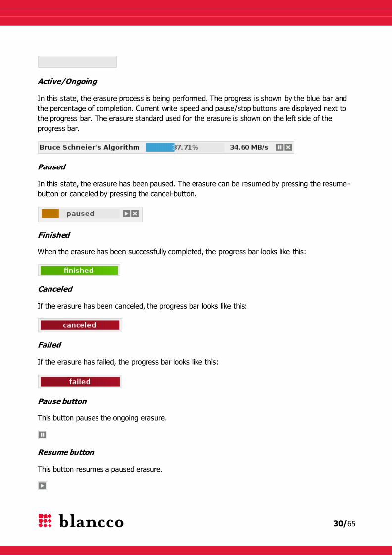
Active/Ongoing
In this state, the erasure process is being performed. The progress is shown by the blue bar and
the percentage of completion. Current write speed and pause/stop buttons are displayed next to
the progress bar. The erasure standard used for the erasure is shown on the left side of the
progress bar.
Paused
In this state, the erasure has been paused. The erasure can be resumed by pressing the resume-
button or canceled by pressing the cancel-button.
Finished
When the erasure has been successfully completed, the progress bar looks like this:
Canceled
If the erasure has been canceled, the progress bar looks like this:
Failed
If the erasure has failed, the progress bar looks like this:
Pause button
This button pauses the ongoing erasure.
Resume button
This button resumes a paused erasure.
31/65
Cancel button
This button cancels an ongoing erasure.
4.2.3.2.6 Drive info-icons
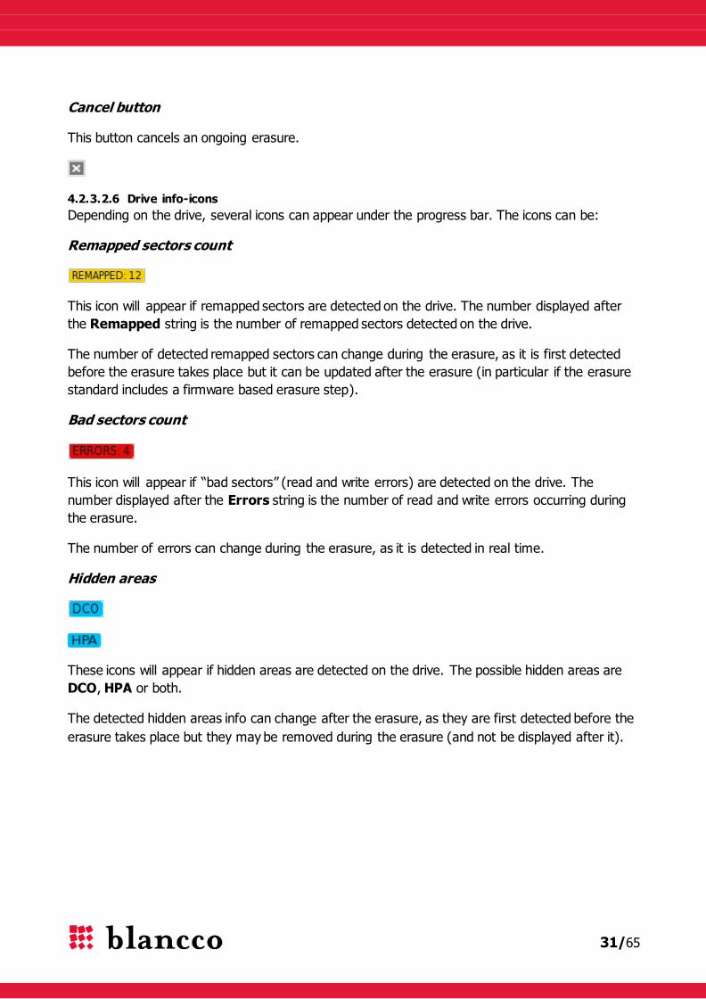
Depending on the drive, several icons can appear under the progress bar. The icons can be:
Remapped sectors count
This icon will appear if remapped sectors are detected on the drive. The number displayed after
the Remapped string is the number of remapped sectors detected on the drive.
The number of detected remapped sectors can change during the erasure, as it is first detected
before the erasure takes place but it can be updated after the erasure (in particular if the erasure
standard includes a firmware based erasure step).
Bad sectors count
This icon will appear if “bad sectors” (read and write errors) are detected on the drive. The
number displayed after the Errors string is the number of read and write errors occurring during
the erasure.
The number of errors can change during the erasure, as it is detected in real time.
Hidden areas
These icons will appear if hidden areas are detected on the drive. The possible hidden areas are
DCO, HPA or both.
The detected hidden areas info can change after the erasure, as they are first detected before the
erasure takes place but they may be removed during the erasure (and not be displayed after it).
32/65
4.3 “Input & edit”-step
The “Input & edit”-step is the second defined default step. In this step, the erasure report can be
edited before, during and after the erasure.
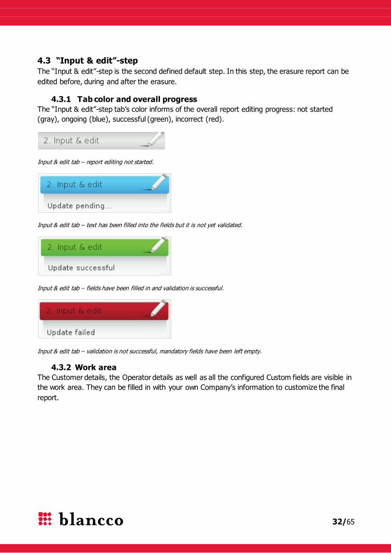
4.3.1 Tab color and overall progress
The “Input & edit”-step tab’s color informs of the overall report editing progress: not started
(gray), ongoing (blue), successful (green), incorrect (red).
Input & edit tab – report editing not started.
Input & edit tab – text has been filled into the fields but it is not yet validated.
Input & edit tab – fields have been filled in and validation is successful.
Input & edit tab – validation is not successful, mandatory fields have been left empty.
4.3.2 Work area
The Customer details, the Operator details as well as all the configured Custom fields are visible in
the work area. They can be filled in with your own Company’s information to customize the final
report.

33/65
4.3.2.1 Customer & Operator information
These fields contain extra information that:
- is either related to the Customer i.e. the company the drives to erase come from,
- or is related to the Operator i.e. the company carrying out the erasure.
These field names are static and cannot be added, removed or modified. However, their default
values can be predefined with the B5CT and/or edited in Blancco 5:
Name Example Description
Customer name
Example Company
Name of the company which owns the
machines to erase (can be different than
the Licensee).
Customer location Anytown
Location/address of the aforementioned
customer.
Erasure provider
Erasure Company’s name
The company using the tool and
performing the erasure (can be different
than the Licensee and the Customer).
Erasure technician Erasure Company’s employee
The person performing the erasure
process.
4.3.2.2 Custom fields
Custom fields are usually created and filled in by the Operator i.e. the person or company that
carries out the drives’ erasure.
Custom fields are created with the B5CT. The user can customize them:
- By giving them any name he/she wants,
34/65
- By filling them in with any default value,
- By setting them as normal or mandatory fields (the latter are marked with a little * sign:
report can’t be sent / saved until those fields have been filled),
- Examples of custom fields’ names: “Asset ID”, “Asset type”, “Asset value”, “Destroy
asset”…
For more information, refer to the B5CT user manual.
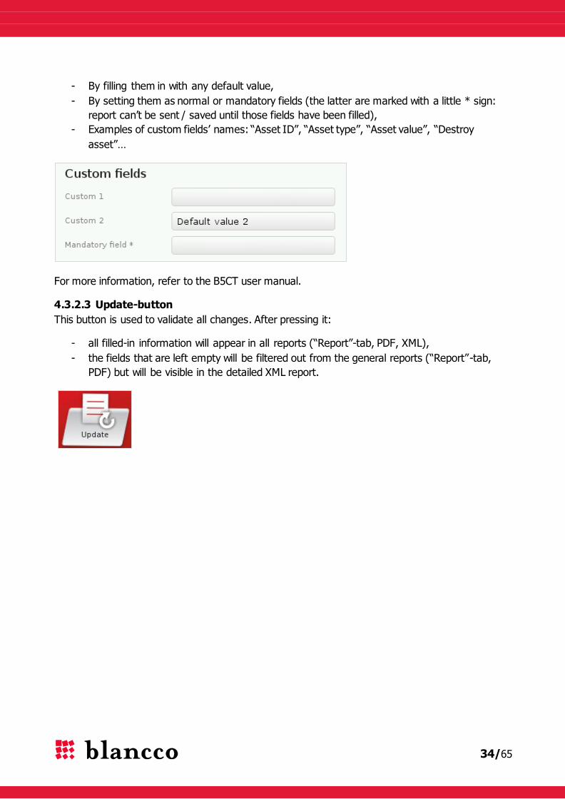
4.3.2.3 Update-button
This button is used to validate all changes. After pressing it:
- all filled-in information will appear in all reports (“Report”-tab, PDF, XML),
- the fields that are left empty will be filtered out from the general reports (“Report”-tab,
PDF) but will be visible in the detailed XML report.

35/65
4.4 “Report”-step
The “Report”-step is the third and final defined default step. In this step, the report can be viewed
before, during and after the erasure.
4.4.1 Tab color and overall progress
The “Report”-step tab’s color informs of the overall report backing-up progress: not started (gray),
ongoing (blue), successful (green), failed (red). The report can be saved, sent or both sent and
saved.
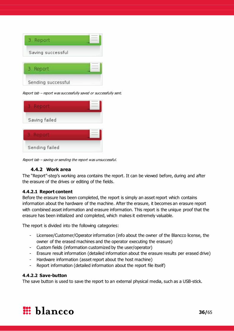
Report tab – report can be viewed but has not yet been backed up.
Report tab – report is being saved or is being sent.
36/65
Report tab – report was successfully saved or successfully sent.
Report tab – saving or sending the report was unsuccessful.
4.4.2 Work area
The “Report”-step’s working area contains the report. It can be viewed before, during and after
the erasure of the drives or editing of the fields.
4.4.2.1 Report content
Before the erasure has been completed, the report is simply an asset report which contains
information about the hardware of the machine. After the erasure, it becomes an erasure report
with combined asset information and erasure information. This report is the unique proof that the
erasure has been initialized and completed, which makes it extremely valuable.
The report is divided into the following categories:
- Licensee/Customer/Operator information (info about the owner of the Blancco license, the
owner of the erased machines and the operator executing the erasure)
- Custom fields (information customized by the user/operator)
- Erasure result information (detailed information about the erasure results per erased drive)
- Hardware information (asset report about the host machine)
- Report information (detailed information about the report file itself)
4.4.2.2 Save-button
The save button is used to save the report to an external physical media, such as a USB-stick.

37/65
Plug your external device (USB-stick) into the machine, then press the “Save” button. The
following window is shown:
- Choose the desired media from the “Drive” list.
- The name of the report file is displayed on the “Filename” field. The default name of the
report follows the format: Date(yyyymmdd)_Time(hh24miss)_report.
o A report named “20130211_235808_report” was created the 11th of February, 2013
at 11:58:08 PM.
o This name can eventually be changed before saving the report to the external
media.
- Choose the report format from the “Format” list. Possible report formats are:
o XML (report created with an XML extension, can be imported to the BMC),
o PDF (report created with a PDF extension, can be printed but cannot be imported to
the BMC),
o XML+PDF (two reports are created, one as a PDF-file and other one as a XML-file)
- Press “Save” to save the report or “Cancel” to exit this window.
If the saving was successful then the following pop up is shown:
38/65
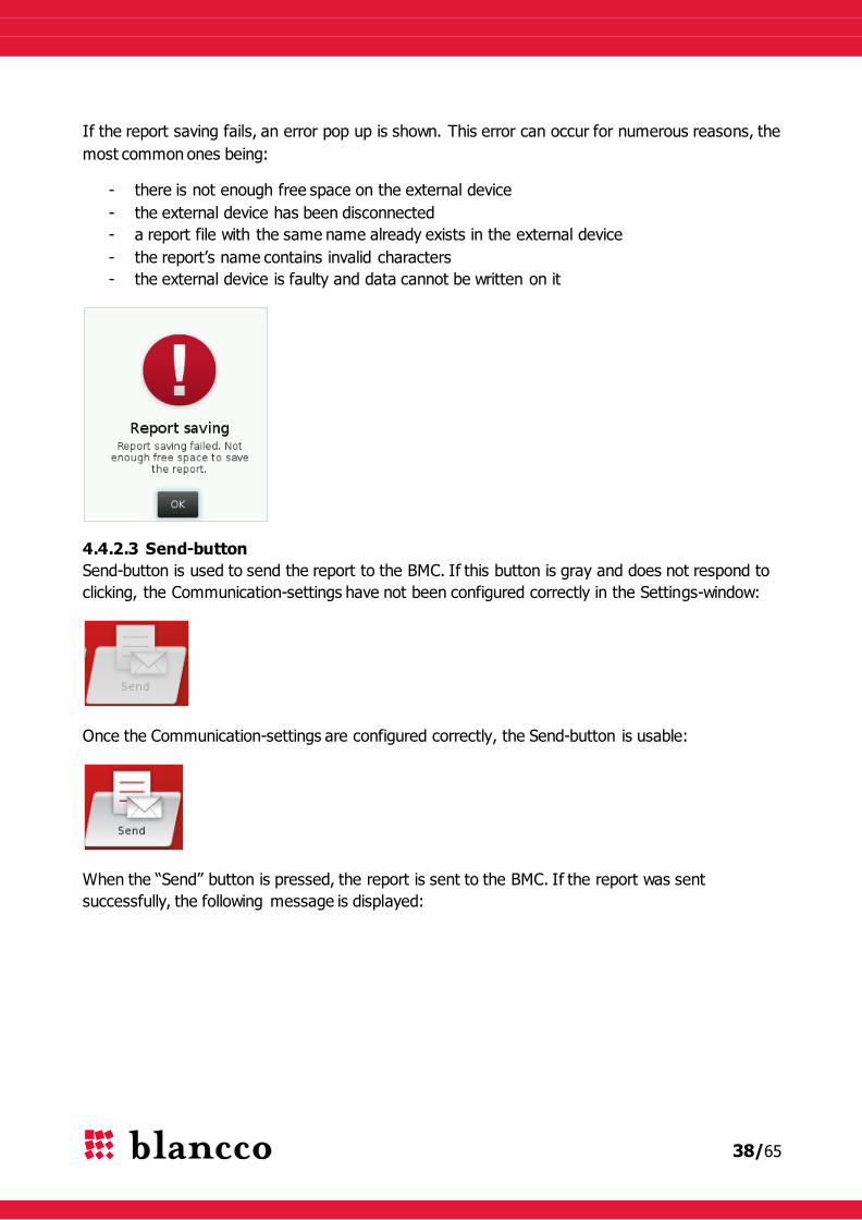
If the report saving fails, an error pop up is shown. This error can occur for numerous reasons, the
most common ones being:
- there is not enough free space on the external device
- the external device has been disconnected
- a report file with the same name already exists in the external device
- the report’s name contains invalid characters
- the external device is faulty and data cannot be written on it
4.4.2.3 Send-button
Send-button is used to send the report to the BMC. If this button is gray and does not respond to
clicking, the Communication-settings have not been configured correctly in the Settings-window:
Once the Communication-settings are configured correctly, the Send-button is usable:
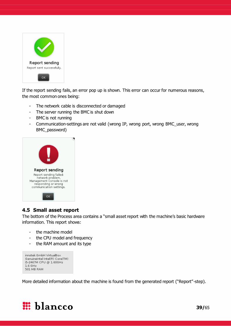
When the “Send” button is pressed, the report is sent to the BMC. If the report was sent
successfully, the following message is displayed:
39/65
If the report sending fails, an error pop up is shown. This error can occur for numerous reasons,
the most common ones being:
- The network cable is disconnected or damaged
- The server running the BMC is shut down
- BMC is not running
- Communication-settings are not valid (wrong IP, wrong port, wrong BMC_user, wrong
BMC_password)
4.5 Small asset report
The bottom of the Process area contains a “small asset report with the machine’s basic hardware
information. This report shows:
- the machine model
- the CPU model and frequency
- the RAM amount and its type
More detailed information about the machine is found from the generated report (“Report”-step).

40/65
5 KEYBOARD CONTROLS
Blancco 5 can exclusively be controlled with the keyboard only (no mouse required).
5.1 Generic controls
5.1.1 Tab key
The Tab key moves the focus inside a window or inside the Work area (from element to element).
The focus moves from left to right, top to bottom, in a circular way. By combining the Shift-key
with the Tab-key (Shift + Tab), the direction is reversed (goes backwards: from right to left,
bottom to top).
The -button that is visible in the top right of popup/dialog windows cannot be reached via the
Tab key. Use the Escape-key to close such windows.
5.1.2 Arrow keys
Whenever the focus is:
On an area that contains a horizontal and/or vertical scroll-bar (Report-step, Hexviewer,
Help window, EULA window…):
o the Arrow keys can be used to go up/down/left/right inside that area.
On a drop-down list (list of erasure standards, list of languages, list of keyboard
layouts…):
o the Arrow keys can be used to scroll those lists,
o combining the Alt key with the down arrow (Alt + down arrow) will expand these
lists.
On a slider’s handle (verification slider):
o the Arrow keys can be used to move the handle.
On a scrollable container with elements (list of drives in the Advanced-view of the Erasure-
step):
o the Arrow keys can be used to move from one element to another,
o use up & down arrows to move between the rows (drives),
o use left & right arrows to access the drive’s Pause/Resume and Cancel buttons.
5.1.3 Space bar
Whenever the focus is:
On top of a check-box:
o the Space bar selects/deselects it.
On top of a button:
o the Space bar pushes it.
5.1.4 Enter key
Whenever the focus is:
On top of a button:
41/65
o the Enter key pushes it.
On an element of an expanded drop-down list:
o the Enter key selects that element.
On top of a link:
o the Enter key opens it.
5.1.5 Escape key
Whenever the focus is:
On top of an expanded drop-down list:
o the Esc key collapses it.
Inside an open window (popup, dialog):
o the Esc key closes it without saving any change (equivalent of Cancel/Close or ).
5.2 Accessing the Header area
The buttons of the Header area are accessed exclusively with the function keys.
5.2.1 F1-F4 function keys
F1 – pushes the Help-button (opens the Help-window).
F2 – pushes the Report issue-button (opens the Report issue-window).
F3 – pushes the Settings-button (opens the Settings-window).
F4 – pushes the Hexviewer-button (opens the Hexviewer-window).
These buttons might differ depending on the version of the software. The logic always follows the
same formula: first button on the left of Shutdown-button is F1, next one on the left is F2, etc…
5.2.2 F10 function key
Pressing F10 is similar to pushing the Shutdown-button (opens the Shutdown-popup).
5.3 Accessing the Process area
The steps of the Process area are accessed exclusively with the key combinations Ctrl key +
Number keys (1, 2, 3…).
Ctrl + 1 – selects the first step (Erasure-step).
Ctrl + 2 – selects the second step (Input & edit-step).
Ctrl + 3 – selects the third step (Report-step).
These buttons might differ depending on the configuration of the software. The logic always
follows the same formula: the first step is accessed with Ctrl + 1, the second step is Ctrl + 2, etc...
5.4 Navigation inside the Work area
5.4.1 Erasure-step
The drives, erasure options and the Erase-button can be accessed with the Tab key and the Arrow
keys, but this step has also few key combinations.

42/65
5.4.1.1 Ctrl + M
This key combination switches between Standard- & Advanced-views/modes.
5.4.1.2 Ctrl + E
This key combination pushes the Erase-button (starts the erasure).
5.4.1.3 Ctrl + A
When in the Advanced-view, this key combination selects all drives for erasure.
5.4.2 Input&edit-step
The fields and the Update-button are accessed exclusively with the Tab key.
5.4.3 Report-step
The elements and the Save- and Send-buttons are accessed exclusively with the Tab key. Use the
Arrow keys to scroll the report content.
43/65
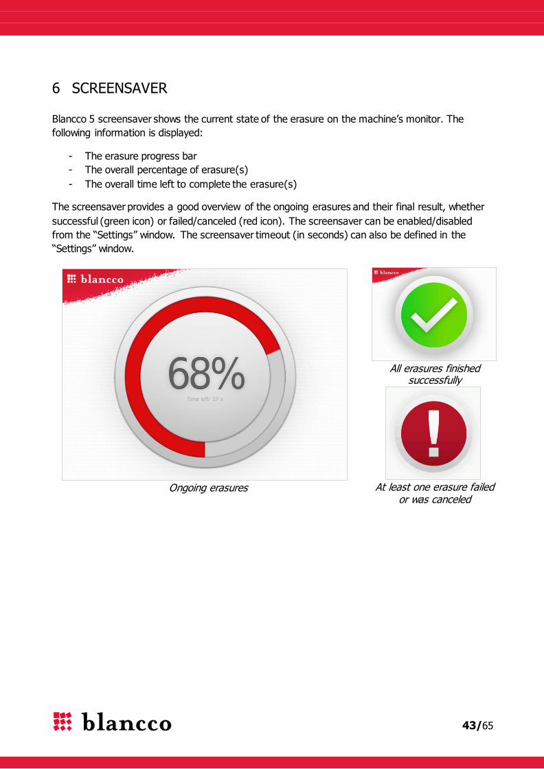
6 SCREENSAVER
Blancco 5 screensaver shows the current state of the erasure on the machine’s monitor. The
following information is displayed:
- The erasure progress bar
- The overall percentage of erasure(s)
- The overall time left to complete the erasure(s)
The screensaver provides a good overview of the ongoing erasures and their final result, whether
successful (green icon) or failed/canceled (red icon). The screensaver can be enabled/disabled
from the “Settings” window. The screensaver timeout (in seconds) can also be defined in the
“Settings” window.
Ongoing erasures
All erasures finished successfully
At least one erasure failed or was canceled
44/65
7 BLANCCO 5 SECURITY FEATURES
7.1 Booting Options
The Booting Options are a new feature introduced in Blancco 5.4.0. It allows Blancco 5 to be
booted with alternative settings, if there are issues with the default booting.
Blancco 5.5.1 image can be booted in four different ways, each way enabling a different set of
features. These four booting options can be accessed by pressing the up or down arrow key right
after the first Blancco 5 static screen appears ("Blancco - Certified Data Erasure", "Starting Blancco
5", "Screen might turn black momentarily - please wait").
7.1.1 Description
These options are:
1. Normal startup (safe resolution) – Blancco 5 is loaded using a standard/universal
graphical driver. The screen resolution of the GUI is static (1024*768). If any drive is
locked, the Freeze lock removal is attempted just before the erasure process (the screen
turns black for few seconds then restarts and the erasure begins, see the Freeze lock). This
booting option has been tested on several configurations, however the Freeze lock removal
procedure may not work in all machines (the standard/universal graphical driver often
presents display problems when the machine is awakened).
2. Normal startup (native resolution) – Blancco 5 is loaded using any available driver that
corresponds to the graphical card of the machine (the standard/universal graphical driver is
just a fallback). The screen resolution is the native resolution of the machine (1024*768 or
higher). If any of drives is locked, the Freeze lock removal is attempted just before the
erasure process (the screen turns black for few seconds then restarts and the erasure
begins, see the Freeze lock). This booting option works better than the first option in
many/most cases when Freeze lock removal procedure is needed.
3. FLR during startup – This is the default option. The Freeze lock removal process is
carried out during the booting phase, before loading all the system drivers, to increase the
chances to wake up the machine after the freeze lock removal. Then, Blancco 5 is loaded
using any available driver that corresponds to the graphical card of the machine. The
screen resolution is the native resolution of the machine (1024*768 or higher). This
booting option works better than the first option in many/most cases when Freeze lock
removal procedure is needed.
4. Show startup messages – This is the same option than the second one, except that
startup messages are shown in the screen instead of the animated loading screen. This can
be used as a troubleshooting measure for machines where Blancco 5 hangs during the
booting phase.
7.1.2 When to use the booting options?
Depending on the hardware where Blancco 5 is booted, some issues may arise during the Freeze
lock removal process performed by the default booting option (FLR during startup), such as
45/65
screens staying black or unresponsive machines. In these cases, the suggested procedure is the
following:
- Try booting Blancco 5 using the second booting option (Normal startup (native
resolution))
- If problems arise with the aforementioned booting option (black screen, machine is
unresponsive), try booting Blancco 5 using the first option (Normal startup (safe
resolution))
If problems arise during the booting phase (Blancco 5 hangs), try booting Blancco 5 using the
fourth option (Show startup messages), take note of the last messages shown in the screen
before the hanging and contact the Blancco Support.
These options are hidden by default and the time limit to select a booting option other than the
default one is 5 seconds.
7.2 Software version
The version number of the software is always on the top left of the graphical user interface, in the
Header area.
7.3 Detecting HDDs
Magnetic storage media, such as HDDs, use physical addressing when storing information on a
media device. With this addressing, the HDD is divided into smaller parts that can be appointed
according to certain parameters. In magnetic media the aforementioned physical parameters are
sectors, cylinders and heads. During the computer usage, these parameters enable the operating
systems to locate the information on a HDD but they also define the size and storage base of a
HDD. A reliable and protected detection of these hardware level parameters is essential and the
erasure software must be capable of detecting the correct HDD sizes regardless of the techniques
used in altering the HDD information. Failure to accurately detect the HDD may result in an
incomplete erasure.
All Blancco data erasure tools utilize hardware level detection for HDDs which enables the software
to detect correct HDD sizes regardless of faulty or incorrect BIOS-set HDD values. As a result, the
overwriting process will reach the whole HDD surface, leaving no areas untouched.
7.4 Bad sector (read/write error) handling
Even though the incorrectly configured, faulty or damaged configurations cause a potentially
remarkable data security risk there are also other gaps that need to be addressed in order to
guarantee a secure data erasure process. HDDs can contain damaged areas that cannot anymore
be accessed with read or write command, which makes those areas unusable. In data erasure
terms, these areas are called physical bad sectors. Data erasure tools must be able to detect and
especially report them.
Blancco 5 keeps track of the data erasure procedure and informs if the data erasure (overwrite)
cannot be performed due to some error on the HDD. E.g. in case there are any bad sector(s)
found on the HDD, the software will try to write a data block to the defective area. If the area
46/65
remains “silent”, Blancco will try to write a smaller block (half of the original block size) to the
defective area in order to overwrite the maximum amount of data. The same procedure will
continue until the software tries to write the smallest possible block to the drive and if unable to
do so after three tries, the sector will be marked as a physical bad sector. This procedure offers an
extremely accurate erasure even in cases of bad sectors so that all the possible areas will be
erased and only the real bad sectors/areas will be reported. The bad sectors will be reported in the
user interface as well as in the erasure report which is produced after each erasure.
If there was a read/write error detected during the erasure process (during overwriting rounds or
verification), the erasure result will be “Not erased”.
The verification mechanism on Blancco 5 is configured to provide the statistically most effective
analysis of the drive on any given verification percentage (through checking sectors at evenly
spaced intervals). The higher the percentage selected by the user means that a larger amount of
the drive will be analyzed, resulting in a greater chance that bad sectors (read/write errors) will be
detected.
7.5 Remapped sectors
Modern drives have a lot of functions for self-testing, self-recovering and keeping track of their
state. One of the possibilities is sector remapping. This allows the drives to detect and hide the
sectors, which will either be or have become impossible to access. The drives have a so-called
spare area intended precisely for this. When a failed sector is detected, the drive controller assigns
the address of the sector to a new one in the spare area. The address remains the same but the
owner is changed. The remapped sector may contain some of the user's data. With Blancco 5, the
remapped sectors can be erased.
Remapped sector erasure can be selected with any overwriting standard Blancco 5 supports.
Erasing remapped sectors can be a time consuming process depending on the drive size and
speed.
The erasure standards (Extended) Firmware based erasure, BSI-GS/E, NIST 800-88 Purge – ATA
and Blancco SSD Erasure include de facto a remapped sector erasure, so selecting or not selecting
the “Erase remapped sectors” checkbox won't have any effect on them.
Warning! Avoid turning off the computer, exiting the program, disconnecting the drive(s),
pausing/cancelling the erasure during the Remapped Sector erasure process or the drive(s) may
be damaged.
Warning! Disable the BIOS HDD detection when using Remapped Sector erasure. In many
computers the remapped sectors can be erased even without changing BIOS settings, but by
disabling the BIOS HDD detection some problems can be avoided.
7.6 Freeze lock
If the drive is Freeze locked, removal of the drive’s hidden areas or issuing the firmware based
erasure commands is not possible.

47/65
Blancco 5 detects if at least one of the drives about to be erased is Freeze locked. When a Freeze
lock is detected, Blancco 5 tries automatically to remove the Freeze lock by power cycling the
machine: the machine is put to sleep, the drives’ locks are removed and the machine is woken up.
When this power cycling happens the screen usually goes black for a few seconds before
returning. As the machine is power cycled, Blancco 5 attempts to remove the freeze locks on all
locked drives at once, so this process occurs at most once per session.
Warning! With some hardware configurations, the screen might not turn back on. This depends
heavily on the machine’s graphical card and/or the graphical driver used, as some devices do not
wake up properly. The erasure process is either interrupted or continues in the background. If
such a situation comes to happen, please refer to the Problems with the Freeze lock removal
section for advices.
7.7 Hidden areas in a drive
There can be hidden areas in a storage device (HDD, SSD) which cannot be normally accessed
even via the BIOS. Blancco 5 can detect and remove these areas. The areas are:
7.7.1 Host Protected Area (HPA)
Blancco 5 can be configured to detect and automatically remove the Host Protected Area. The HPA
is commonly used to store the recovery part of the operating system and can contain sensitive
data. When a Host Protected Area is found, the entire area is automatically removed.
Note. In order to guarantee the functionality of this option, please disable the BIOS HDD drive
detection for proper detection and execution of Blancco 5. In some cases the computer must be
rebooted in order to remove the HPA.
7.7.2 Device Configuration Overlay (DCO)
Device Configuration Overlays (DCO) is another but less known optional feature set. It first
appeared in the ATA-6 standard. DCO enables the possibility to create a special partition in a drive
that the user or the operating system cannot access. This special area of the drive creates a risk
that some data might be left on the drive after the erasure unless the erasure product is capable
of detecting and also extending and erasing DCO areas. Blancco 5 can be configured to
automatically detect and remove the DCO area.
The following table contains a summary of different locking/protection methods supported by
Blancco 5:
Drive interfaces ATA SATA SCSI Fibre Channel
Bad sector detection YES YES YES YES
Remapped sectors (detection) YES YES YES YES
Remapped sectors (erasure) (2) YES (2) YES YES YES
Host Protected Area – HPA
(erasure, removal)
(2) YES (2) YES (1) Not existing (1) Not existing
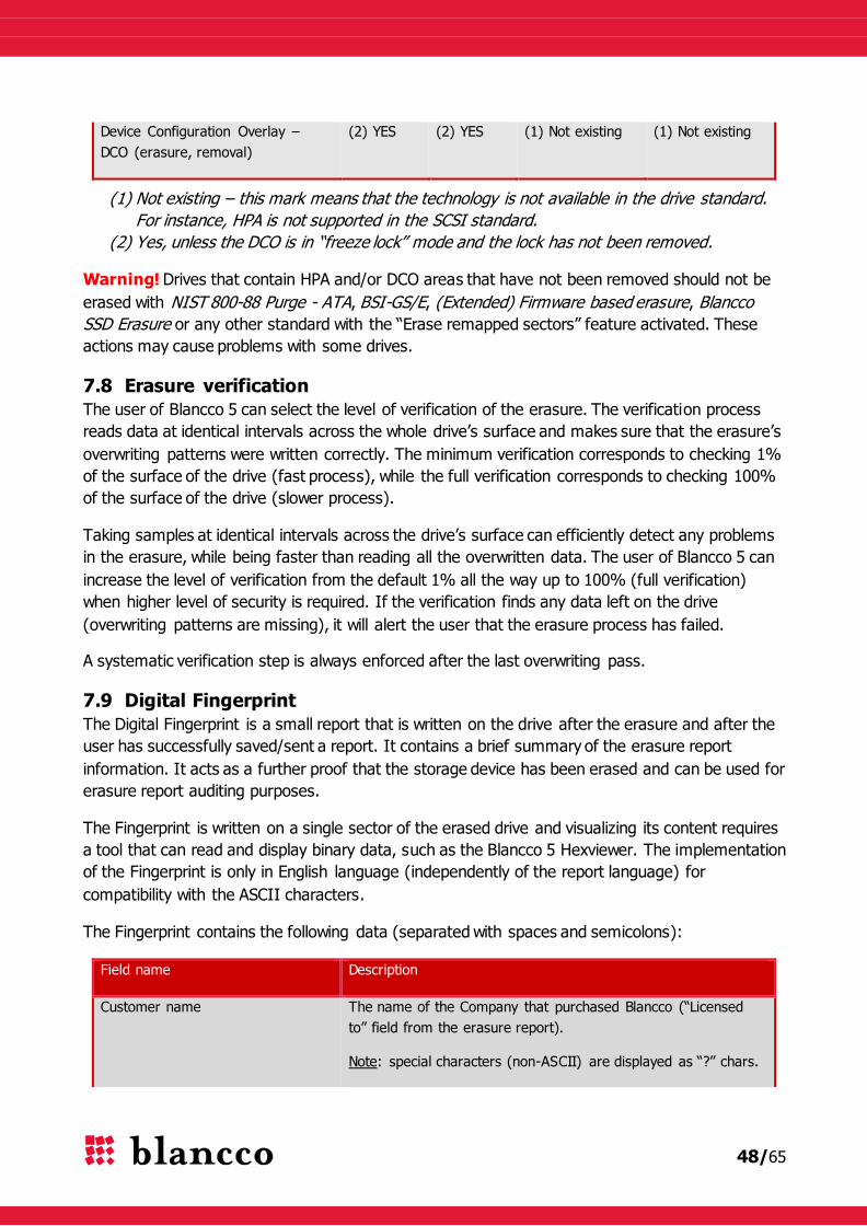
48/65
Device Configuration Overlay –
DCO (erasure, removal)
(2) YES (2) YES (1) Not existing (1) Not existing
(1) Not existing – this mark means that the technology is not available in the drive standard.
For instance, HPA is not supported in the SCSI standard.
(2) Yes, unless the DCO is in “freeze lock” mode and the lock has not been removed.
Warning! Drives that contain HPA and/or DCO areas that have not been removed should not be
erased with NIST 800-88 Purge - ATA, BSI-GS/E, (Extended) Firmware based erasure, Blancco
SSD Erasure or any other standard with the “Erase remapped sectors” feature activated. These
actions may cause problems with some drives.
7.8 Erasure verification
The user of Blancco 5 can select the level of verification of the erasure. The verification process
reads data at identical intervals across the whole drive’s surface and makes sure that the erasure’s
overwriting patterns were written correctly. The minimum verification corresponds to checking 1%
of the surface of the drive (fast process), while the full verification corresponds to checking 100%
of the surface of the drive (slower process).
Taking samples at identical intervals across the drive’s surface can efficiently detect any problems
in the erasure, while being faster than reading all the overwritten data. The user of Blancco 5 can
increase the level of verification from the default 1% all the way up to 100% (full verification)
when higher level of security is required. If the verification finds any data left on the drive
(overwriting patterns are missing), it will alert the user that the erasure process has failed.
A systematic verification step is always enforced after the last overwriting pass.
7.9 Digital Fingerprint
The Digital Fingerprint is a small report that is written on the drive after the erasure and after the
user has successfully saved/sent a report. It contains a brief summary of the erasure report
information. It acts as a further proof that the storage device has been erased and can be used for
erasure report auditing purposes.
The Fingerprint is written on a single sector of the erased drive and visualizing its content requires
a tool that can read and display binary data, such as the Blancco 5 Hexviewer. The implementation
of the Fingerprint is only in English language (independently of the report language) for
compatibility with the ASCII characters.
The Fingerprint contains the following data (separated with spaces and semicolons):
Field name Description
Customer name The name of the Company that purchased Blancco (“Licensed
to” field from the erasure report).
Note: special characters (non-ASCII) are displayed as “?” chars.

49/65
Date & time of erasure completion Displayed with the format: yyyy-mm-dd hh:mm:ss
Blancco software version e.g. Blancco 5 5.4.1
Drive serial number Also displayed in the “Erasure”-step.
Erasure status "Erased" or "Not Erased".
Erasure information message e.g. “User canceled the erasure”
Note: this message may be truncated in case the Fingerprint
content is longer than 512 chars (sector size).
Unique report ID Erasure report UUID.
Key ID Same than the erasure report’s key_id field.
Digital signature Encoded on 64-chars. Similar to the erasure report’s digital
signature but generated from the Fingerprint content itself.
The Digital Fingerprint is disabled by default. Enabling it, as well as setting its sector location, is
done via the Blancco 5 Configuration Tool.
7.10 Hardware not supported by Blancco 5
7.10.1 Unsupported processors
Blancco 5 supports x86 processor-based machines, however some machines use different
processor architectures (RISC, ARM…) that Blancco 5 does not support and cannot directly erase.
Sun SPARC based servers can be erased using our Blancco SPARC product.
Fortunately, data storage devices are always the same regardless of the hardware (whether x86 or
RISC architecture) and Blancco can be used to erase the drives from these machines by
connecting them to an x86 processor-based computer. A typical solution consists of removing
those drives from their non-supported server and connecting them to a supported x86 processor-
based “erasure station” for erasure.
Blancco 5 cannot presently boot on (nor erase) 32-bit UEFI machines (even if they are x86
processor-based). This is the case of e.g. several tablets using the Atom processor with a system
on chip platform such as the “Clover Trail” platform.
7.10.1 Unsupported drives
Drives can be manufactured with different sector sizes. Although drives with sector sizes of 512
bytes are the most popular (traditional formatting), some rare drives possess sectors with slightly
bigger sizes of e.g. 520 bytes. Newer drives use 4096 bytes sectors (Advanced Format).
Blancco 5 supports drives with 512 bytes sector size. Drives with e.g. 520 bytes sector size are
currently not properly supported. Drives with 4096 bytes sector size are supported if they offer a
50/65
512 byte emulation layer (Advanced Format 512 emulation or 512e), but they are not properly
supported if they do not provide that emulation layer (Advanced Format 4K native or 4Kn).
7.10.2 SSDs
Although Blancco 5 can identify and erase all kind of Hard Disk Drives (where data is stored
magnetically on rotating disks), there are some caveats involved regarding the erasure of Solid
State Drives (SSD). SSDs differ from HDDs in that data is stored electronically on transistor arrays.
Please refer to the chapter Guidelines for Using SSD Erasure Method for more information.
If the documentation does not help you, please engage with your local Blancco representative
regarding the erasure of these drives.
7.10.3 RAID-controllers
Blancco 5 supports most RAID-controllers attached to SCSI drives. However, Blancco 5 does not
currently fully support all RAID-controllers attached to SAS or SATA drives, with the exception of
the MegaRAID controller and HP Smart Array.
The MegaRAID controllers can be purchased by different original equipment manufacturers (OEM)
or brands which can resell them with their own firmware: the support of the MegaRAID depends
heavily on the firmware that has been embedded into the controller. Currently Blancco 5 supports
MegaRAID controllers branded by LSI (SAS and SATA drives) and Dell (SAS drives only). Support
of other brands (mainly HP and Intel) is not fully guaranteed.
Support for other SAS/SATA RAID controllers will be implemented in upcoming versions.
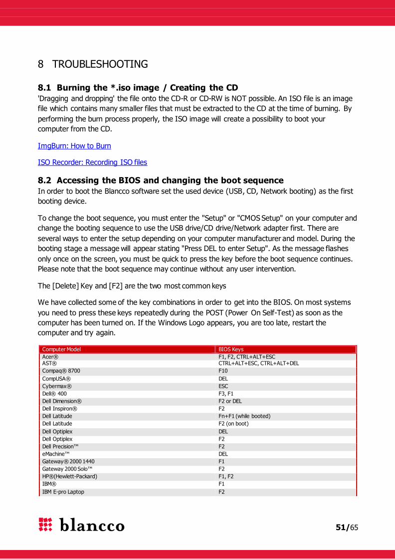
51/65
8 TROUBLESHOOTING
8.1 Burning the *.iso image / Creating the CD
'Dragging and dropping' the file onto the CD-R or CD-RW is NOT possible. An ISO file is an image
file which contains many smaller files that must be extracted to the CD at the time of burning. By
performing the burn process properly, the ISO image will create a possibility to boot your
computer from the CD.
ImgBurn: How to Burn
ISO Recorder: Recording ISO files
8.2 Accessing the BIOS and changing the boot sequence
In order to boot the Blancco software set the used device (USB, CD, Network booting) as the first
booting device.
To change the boot sequence, you must enter the "Setup" or "CMOS Setup" on your computer and
change the booting sequence to use the USB drive/CD drive/Network adapter first. There are
several ways to enter the setup depending on your computer manufacturer and model. During the
booting stage a message will appear stating "Press DEL to enter Setup". As the message flashes
only once on the screen, you must be quick to press the key before the boot sequence continues.
Please note that the boot sequence may continue without any user intervention.
The [Delete] Key and [F2] are the two most common keys
We have collected some of the key combinations in order to get into the BIOS. On most systems
you need to press these keys repeatedly during the POST (Power On Self-Test) as soon as the
computer has been turned on. If the Windows Logo appears, you are too late, restart the
computer and try again.
Computer Model BIOS Keys
Acer® F1, F2, CTRL+ALT+ESC AST® CTRL+ALT+ESC, CTRL+ALT+DEL
Compaq® 8700 F10
CompUSA® DEL
Cybermax® ESC
Dell® 400 F3, F1
Dell Dimension® F2 or DEL
Dell Inspiron® F2
Dell Latitude Fn+F1 (while booted)
Dell Latitude F2 (on boot)
Dell Optiplex DEL
Dell Optiplex F2
Dell Precision™ F2
eMachine™ DEL
Gateway® 2000 1440 F1
Gateway 2000 Solo™ F2
HP®(Hewlett-Packard) F1, F2
IBM® F1
IBM E-pro Laptop F2
52/65
IBM PS/2® CTRL+ALT+INS after CTRL+ALT+DEL
IBM Thinkpad® (newer) Windows: Start | Programs | Thinkpad CFG.
Intel® Tangent DEL
Micron™ F1, F2, or DEL
Packard Bell® F1, F2, DEL
Sony® VIAO F2, F2
Tiger DEL
Toshiba® 335 CDS ESC
Toshiba Protege ESC
Toshiba Satellite 205 CDS F1
Toshiba Tecra F1 or ESC
8.3 Booting on machines with UEFI
Blancco 5 may face some issues when booting on machines that use EFI/UEFI.
The B5 UEFI support (available from 5.4.x versions) requires some mandatory conditions:
Booting from a CD does not work properly, prefer instead booting with a bootable USB-
stick previously formatted with Blancco USB Creator.
o The USB Creator version has to be at least the 2.1.0.58 (or newer).
The UEFI machine where Blancco 5 is booted has to be an x86 and 64-bit processor
(Blancco 5 UEFI infrastructure is 64-bit).
o B5 cannot presently boot on (nor erase) 32-bit UEFI machines.
8.3.1 Disabling the Secure Boot
Any PC with a Windows 8 logo sticker has a “Secure boot” enabled by default. Secure boot is an
UEFI feature that can make Windows 8 very resistant to low-level malware such as rootkits.
Blancco 5 may not properly boot on a machine where the Secure Boot is enabled, in which case
this feature has to be manually disabled.
The following steps will demonstrate how to enable or disable the Secure Boot in the PC's UEFI
settings:
8.3.1.1 General steps
1. Boot to UEFI Firmware Settings.
2. In the motherboard's UEFI firmware settings, go to the Security/Authentication (or
similar) menu, select the Secure Boot option and disable it.
3. Exit the menu and select Save Changes and Exit. This reboots the machine.
Secure Boot can be enabled again, following the same logical steps.
8.3.1.2 Windows Surface Pro
1. Plug in a USB keyboard to the device.
2. Power on the device and let it boot to the Windows login screen.
3. Press the power icon on the bottom right corner of the screen. Hold down left shift key and
select restart.
4. The device should reboot into a blue "Choose an Option" screen
5. Select "Troubleshoot" -> "Advanced Options" -> "UEFI Firmware Settings" -> "Restart".
53/65
6. UEFI firmware setup screen should show up. Make sure that "Secure boot control" is
disabled and save the settings.
8.3.2 Booting with a Blancco 5 USB-stick
It is possible to boot Blancco 5.5.1 on a machine that has UEFI with a bootable USB-stick.
Nevertheless, changing the booting options (see the Booting Options) may not work on these
machines as only the default booting option’s parameters are taken into account.
Try the following to overcome this issue:
- If the machine has UEFI and BIOS, the easiest solution is to use the BIOS-mode to boot
the machine.
- If the machine has UEFI and no BIOS, you can create a bootable Blancco 5 USB-stick with
the Blancco USB Creator 2.1.0.58 or newer. This version (or newer) adds the Booting
Options as a second menu right after the main boot menu.
8.4 Blancco 5 hangs during the booting
You may find yourself with a machine where Blancco 5 hangs during the booting phase. If this
situation occurs:
1. Boot Blancco 5 and press the up or down arrow key right after the first Blancco 5 static
screen appears ("Blancco - Certified Data Erasure", "Starting Blancco 5", "Screen might
turn black momentarily - please wait").
2. Select the booting option “Show startup messages” which will display startup messages
during the booting instead of the animated loading screen.
3. Take note of the last messages shown in the screen (before the hanging), contact the
Blancco Support and provide them with the messages.
8.5 Booting without a display adapter
Blancco 5 can be booted and used without a display adapter, but it must be remotely controlled
via the BMC 3.
The following requirements must be met:
1. The process has to be set as "Manual".
Default erasure process, this can also be configured via the B5CT
2. The Blancco 5 image has to be remotely controlled via the BMC 3 and the correct
communication settings have to be in place.
This can be configured via the B5CT (erasure control = “Blancco Management
Console remote”, communication settings filled in).
If the communication settings are not correct, Blancco 5 will run, but it will not be
able to receive any orders from the BMC 3.
The BMC 3 can start the erasure remotely, monitor it and fetch the erasure report
in the end.
Any other configuration will result in a non-functional Blancco 5 image.

54/65
In case the booting is done via USB-stick, the line
"splashimage=/syslinux/blancco.xpm"
has to be removed from the menu.lst file on the bootable usb-sticks root. Otherwise the USB
booting will not work.
8.6 SATA drives not detected/not available in the User interface
1. Problem description:
Blancco 5 has started and the drive selection shows one or more drives are missing from the drive
selection.
2. Problem explanation:
One or more SATA drives in IDE/ATA-mode cannot be detected or are not showing in the Blancco
5 User Interface.
Drives might also be broken.
3. Problem solution:
SATA drives need to be set in either “AHCI” or “SATA native” mode (or similar) from
BIOS/UEFI/EFI. The IDE-mode for SATA-drives is not supported by Blancco 5.
8.7 Problems with the Freeze lock removal
If drives are freeze locked, Blancco 5 will attempt to remove the locks by power cycling the
machine: the screen turns black for few seconds before returning. Depending on the booting
option used to boot Blancco 5 (see the Booting Options) or the configured erasure process
(“Manual”, “Semi-automatic” or “Automatic”, see the Processes), the Freeze lock removal may
occur before the GUI starts or right before an erasure process starts. Unfortunately in some
hardware configurations the screen might not turn back on, the user faces then three situations:
I. The screen stays black and an erasure process starts in the background: the drive’s light starts
blinking as the drive is being actively erased.
In this situation only the screen is missing, if the user wants to monitor the erasure a
workaround consists in monitoring it via the BMC 3. After the erasure, the report can also be
fetched. Please refer to the B5CT and BMC manuals for more information about this feature.
II. The screen stays black and nothing starts in the background, however the machine is on
(lights are on, fans are working).
In this situation the screen is missing but the drives are most likely detected and ready for
erasure, if the user wants to start and monitor the erasure a workaround consists in controlling
it via the BMC 3. After the erasure, the report can also be fetched. Please refer to the B5CT
and BMC manuals for more information about this feature.
III. The screen stays black and the machine is unresponsive (lights are off, fans are not working).
In this situation, the Freeze lock removal is most likely paused or has failed. There are three
ways to proceed:
a) With some old machines, the Freeze lock removal process may be paused because the
machine has not got enough time to restart. Try to push the machine’s power button for 1

55/65
second or so to wake up the machine and restart the Blancco GUI / begin the erasure
(after this, you may end up with a working screen or in the case I or II).
b) If the previous does not work, the Freeze lock removal process has likely failed. Next, try to
remove the drive from the machine and connect it to a motherboard that doesn’t enforce
Freeze lock (as the Freeze lock itself is an entirely BIOS dependant feature).
c) Otherwise, unplug either the signal or power cable of the drive. This requires that the
following steps are performed:
1. Shut down the computer system.
2. Unplug the signal cable* or four-wire power cable of the drive while leaving the signal
cable plugged in.
i. To eliminate the danger of Electro Static Discharge, always ground yourself when
removing the power cord.
3. Power on the system and boot the Blancco software.
4. When the software is loading i.e. you see the progress bar, plug the signal/power cord
of the drive back in.
*The signal cable is the preferred option and should be attempted first. If the freeze lock
remains after attempting the boot with signal cable removed, attempt the boot with the
power cord removed.
This method is not recommended by Blancco, as the drive may result damaged in the
process.
Note. Keep in mind to always try the other Booting Options if you face any similar situation.
Warning! Shutting down a machine when the drives are being erased with NIST 800-88 Purge –
ATA, BSI-GS/E, (Extended) Firmware based erasure, Blancco SSD Erasure or any other standard
with the “Erase remapped sectors” feature activated can damage the drives.
8.8 HP Smart Array erasure
1. Problem description:
Some versions/models of the HP Smart Array RAID controller have problems with the erasure
verification (it always fails, regardless of erasure standard) that end up in a failed process (status
= “Not erased”, information = “Verification failed. X sector(s) failed to overwrite”).
2. Problem explanation:
This problem is related to one of the controller’s settings called the surface scan delay. This setting
is the time interval before surface scan analysis activates (possible values from 1-30 sec.). This
time does not begin counting until there are no commands being sent to the controller. Surface
scan analysis is a background process that scans hard drives for bad sectors in fault tolerant
logical drives. In RAID 5 or RAID ADG configurations, surface scan also verifies the consistency of
parity data.
Whenever the erasure part is completed, the surface scan is activated during the verification part
and the controller starts writing some meta/RAID data on the drives. This naturally provokes the
56/65
verification failure and subsequently the whole erasure process failure. Unfortunately, the surface
scan cannot be disabled nor delayed more than 30 seconds.
3. Problem workaround:
This problem can be worked around in the following way:
1. If you happen to have a HP Smart Array RAID controller that presents this problem, before
booting Blancco 5, remove manually all of the RAID logical array configurations.
2. Boot Blancco 5 and follow the normal erasure procedure.
a. Some HBAs will create (a) logical array(s) automatically during boot if they find
unassigned physical disks which don't belong to any RAID array. That automatic
creation has to be manually skipped by pressing ESC (this key press might vary, see
hardware’s documentation for more info) to prevent the problem from happening
again.
57/65
9 APPENDIX 1: SSD SUPPLEMENT
9.1 Guidelines for Using SSD Erasure Method
The following guidelines should be carefully followed when erasing an SSD:
Currently the SSD Erasure Method is only designed to erase SSDs that use the ATA
interface and support the firmware based erasure commands.
o For these drives, the recommended and most thorough erasure standard
available in the software is Blancco's SSD Erasure Standard. However, if
your erasure policy mandates that a different process should be applied for these
drives, other options can be selected but a message will appear on the report
highlighting that an SSD was erased.
o If the SSD you are trying to erase does not support the firmware command or it is
not possible to remove the freeze lock, it is not possible to erase the SSD with
Blancco’s SSD erasure method.
If the SSD-drives are really old models (usually 64GB or smaller), it is recommended that
only one SSD should be erased per machine at a time. The success of erasure can be
affected if two drives are attempted to be erased simultaneously.
The whole drive should be erased, do not erase individual partitions. The use of
firmware based erasure commands will not work on partitions on an SSD. The whole drive
must be erased when using Blancco’s SSD method.
The SSD should not be connected to the machine through additional pieces of hardware
such as USB/FireWire docking stations or PATA/SATA bridges. These could prevent the
software’s ability to issue the firmware erasure command, resulting in a failed process.
There should also be no instance of a RAID configuration for SSDs being erased. If two
SSDs are attached to the host machine, erase a single drive at a time.
If the SSD is not shown on the drive selection screen, or the erasure process cannot be run
due to non-access to firmware based erasure command, one possible solution is to change
the SSD's mode from IDE/ATA-mode to AHCI/Sata Native-mode (via the appropriate
BIOS/UEFI/EFI settings).
9.2 Erasure Result
9.2.1 Status
The end result of an erased SSD (using Blancco’s SSD method) can be one of only two states:
erased (success) and not erased (failed or canceled by the user). An erased drive constitutes one
that has had the whole erasure and verification processes completed, without any identified errors.
The drive is also checked for responsiveness once erased and must present itself in an operational
condition.
9.2.2 Failure Logic
Blancco’s SSD erasure solution follows a multistep erasure and verification process – if any of the
steps fail, the whole process results in a fail. This will result in an erasure report stating that the
erasure process has not been successful. The logic for erasure failure includes the following:

58/65
An SSD being erased must allow the firmware level erasure process to execute. The
software will reject those that do not support these commands, as it is an essential part of
the SSD erasure method. If the software cannot access the firmware command, for any
reason, the drive’s erasure will result in a fail.
o If an SSD has an ATA Master Password set, it is not possible to access the firmware
erasure command or write data to it. This password must be removed before
erasure can be considered. If it is not possible to retrieve the password or somehow
bypass it to unlock the drive, it cannot be erased.
o Drives that have a freeze lock placed on them by the host machine’s BIOS will not
allow access to the firmware erasure command. The latest versions of Blancco’s
software will attempt to automatically remove the lock. Please see the appropriate
part of the manual for further guidelines on removal.
The verification stage of SSD erasure must be completed successfully. If it cannot
complete, the erasure is considered a fail.
o The verification of an SSD must show that no data has remained on the device (at
the logical level). If anomalies are found, the erasure report will state a failed
process.
o There is a possibility that some encrypting SSD models will appear to consistently
fail erasure because verification will fail. See the Failed Erasures section below for
further information on handling.
o Some drives may claim to support certain firmware erasure commands but do not
perform any erasure of data when initiated. If any kind of remnant data is found,
erasure will result in a fail. This is a key security requirement.
o Variations in drive implementations may mean that some drives require a slightly
different process – see Failed Erasures section below for further details.
If the SSD experiences any issues when writing data, erasure is considered to fail due to
possibility that the disk may be faulty or near its end of life.
9.3 Handling Information
9.3.1 Erasure Method
The Blancco erasure software will recognize that an SSD has been detected and will automatically
recommend the use of Blancco’s proprietary method for SSDs. Blancco’s SSD erasure method
combines different techniques to provide the best security available and may exceed the
requirements of other erasure standards. However, the sanitization process is ultimately mandated
by the user of the software and based on their internal policy. For example, the policy may be to
strictly adhere to NIST 800-88 and apply those processes.
59/65
9.3.2 Inoperable Drives
It is possible that SSDs containing firmware that is flawed or have some other operational
deficiency (possibly due to being near to the end of their life) will be subject to malfunction as a
result of the erasure process. This highlights drives that are faulty, regarding their internal erasure
or operational methods. When an event arises whereby an organization decides that an SSD is
considered to be either unserviceable or have security concerns about a drive, possibly due to a
failed erasure process or some other reason, further disposition considerations are required: The
organization handling the SSDs should consider if a destructive process is required on drives that
enter an unresponsive state.
It is also possible that the drive’s OEM (or a data recovery lab) can return the SSD to an
operational condition. Guidance should be sought from the relevant vendor in this case. It should
be noted that (during Blancco’s testing operations) this situation has occurred in only a few cases.
When proceeding with the erasure of drives, it is advised to monitor the results and the effect that
erasure has on them. This will help to identify particular models that become unresponsive post
erasure.
Details on drives that have been found to consistently ‘brick’ after calling firmware erasure
commands can be found at: http://www.blancco.com/ssdinfo.
9.3.3 Failed Erasures
Blancco’s SSD erasure method applies strict verification requirements in order to provide a holistic
approach to SSD erasure and mitigate the issues highlighted by previous research. If a drive does
not support the firmware erasure commands (not because of a BIOS issued freeze lock), then
there are some alternative reason:
o Verification Issues
In the case of drives that consistently fail verification (the report will indicate when this
occurs), it is possible that the drive will require some additional process or analysis. If this
situation arises, please contact your local Blancco representative. Blancco is seeking to
identify these models and attain details of drive operations from OEMs in order to offer
assurances of security and/or specific methods for handling these drives.
o Firmware Upgrading
SSD vendors often develop and issue firmware updates over the lifetime of a drive. The
firmware updates may be developed to address some technical issue or bug found after the
SSDs are released to consumers. Updated SSD firmware usually implies performance
improvements, security updates or improved drive reliability.
60/65
SSD models that consistently fail erasure could benefit from a firmware update to improve
the robustness of their internal operations1. Blancco has provided some information on how
to access the firmware upgrade procedures for various manufacturers. The details can be
found at: http://www.blancco.com/ssdinfo.
1 Blancco is not in a position to guarantee the success or otherwise of firmware updates. There is also no certainty that this will improve the result of erasure.

61/65
10 APPENDIX 2: EXECUTION STEPS OF THE ERASURE STANDARDS
* = depends on the value user has given. See chapter on Verification, for more info.
ESE = Enhanced Secure Erase
SE = Secure Erase
FU = Format Unit
= fallback procedure
10.1 Magnetic standards
HMG Infosec Standard 5, Lower Standard Step #
Overwrite with 0x00 1.
HMG Infosec Standard 5, Higher Standard Step #
Overwrite with 0xAA 1.
Overwrite with 0x55 2.
Overwrite with random byte 3.
Verify data* 4.
DoD 5220.22-M Step #
Overwrite with 0x55 1.
Overwrite with 0xAA 2.
Overwrite with random byte 3.
Verify data* 4.
DoD 5220.22-M ECE Step #
Overwrite with 0x55 1.
Overwrite with 0xAA 2.
Overwrite with random byte 3.
Overwrite with aperiodic random data 4.
Overwrite with 0x55 5.
Overwrite with 0xAA 6.
Overwrite with random byte 7.
Verify data* 8.
Bruce Schneier's Algorithm Step #
Overwrite with 0xFF 1.
Overwrite with 0x00 2.
Overwrite with aperiodic random data 3.
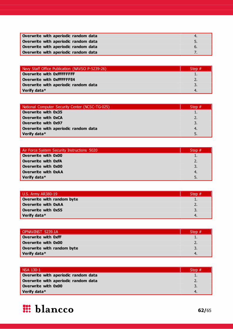
62/65
Overwrite with aperiodic random data 4.
Overwrite with aperiodic random data 5.
Overwrite with aperiodic random data 6.
Overwrite with aperiodic random data 7.
Navy Staff Office Publication (NAVSO P-5239-26) Step #
Overwrite with 0xFFFFFFFF 1.
Overwrite with 0xFFFFFFE4 2.
Overwrite with aperiodic random data 3.
Verify data* 4.
National Computer Security Center (NCSC-TG-025) Step #
Overwrite with 0x35 1.
Overwrite with 0xCA 2.
Overwrite with 0x97 3.
Overwrite with aperiodic random data 4.
Verify data* 5.
Air Force System Security Instructions 5020 Step #
Overwrite with 0x00 1.
Overwrite with 0xFA 2.
Overwrite with 0x00 3.
Overwrite with 0xAA 4.
Verify data* 5.
U.S. Army AR380-19 Step #
Overwrite with random byte 1.
Overwrite with 0xAA 2.
Overwrite with 0x55 3.
Verify data* 4.
OPNAVINST 5239.1A Step #
Overwrite with 0xFF 1.
Overwrite with 0x00 2.
Overwrite with random byte 3.
Verify data* 4.
NSA 130-1 Step #
Overwrite with aperiodic random data 1.
Overwrite with aperiodic random data 2.
Overwrite with 0x00 3.
Verify data* 4.

63/65
Peter Gutmann’s Algorithm Step #
Overwrite with aperiodic random data 1.
Overwrite with aperiodic random data 2.
Overwrite with aperiodic random data 3.
Overwrite with aperiodic random data 4.
Overwrite with 0x555555 5.
Overwrite with 0xAAAAAA 6.
Overwrite with 0x924924 7.
Overwrite with 0x492492 8.
Overwrite with 0x249249 9.
Overwrite with 0x00 10.
Overwrite with 0x11 11.
Overwrite with 0x22 12.
Overwrite with 0x33 13.
Overwrite with 0x44 14.
Overwrite with 0x55 15.
Overwrite with 0x66 16.
Overwrite with 0x77 17.
Overwrite with 0x88 18.
Overwrite with 0x99 19.
Overwrite with 0xAA 20.
Overwrite with 0xBB 21.
Overwrite with 0xCC 22.
Overwrite with 0xDD 23.
Overwrite with 0xEE 24.
Overwrite with 0xFF 25.
Overwrite with 0x924924 26.
Overwrite with 0x492492 27.
Overwrite with 0x249249 28.
Overwrite with 0x6DB6DB 29.
Overwrite with 0xB6DB6D 30.
Overwrite with 0xDB6DB6 31.
Overwrite with aperiodic random data 32.
Overwrite with aperiodic random data 33.
Overwrite with aperiodic random data 34.
Overwrite with aperiodic random data 35.
10.2 Firmware and forced standards
Firmware Based Erasure Step #
-For ATA drive: ESE SE 1.
-For SCSI drive: FU 1.
Verify data* (pattern verification) 2.
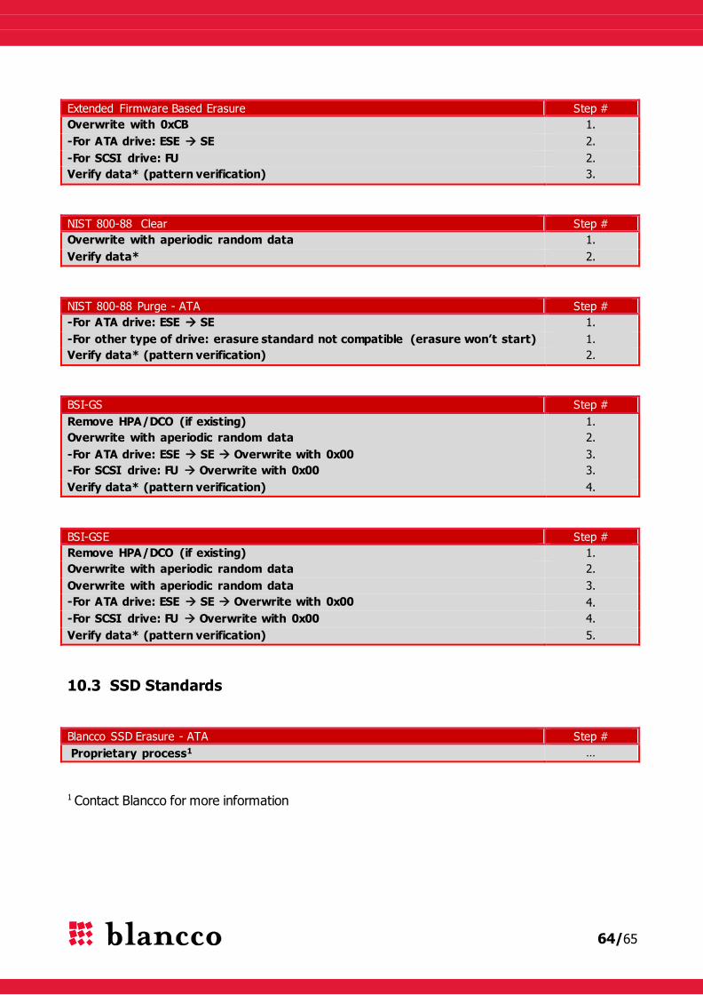
64/65
Extended Firmware Based Erasure Step #
Overwrite with 0xCB 1.
-For ATA drive: ESE SE 2.
-For SCSI drive: FU 2.
Verify data* (pattern verification) 3.
NIST 800-88 Clear Step #
Overwrite with aperiodic random data 1.
Verify data* 2.
NIST 800-88 Purge - ATA Step #
-For ATA drive: ESE SE 1.
-For other type of drive: erasure standard not compatible (erasure won’t start) 1.
Verify data* (pattern verification) 2.
BSI-GS Step #
Remove HPA/DCO (if existing) 1.
Overwrite with aperiodic random data 2.
-For ATA drive: ESE SE Overwrite with 0x00 3.
-For SCSI drive: FU Overwrite with 0x00 3.
Verify data* (pattern verification) 4.
BSI-GSE Step #
Remove HPA/DCO (if existing) 1.
Overwrite with aperiodic random data 2.
Overwrite with aperiodic random data 3.
-For ATA drive: ESE SE Overwrite with 0x00 4.
-For SCSI drive: FU Overwrite with 0x00 4.
Verify data* (pattern verification) 5.
10.3 SSD Standards
Blancco SSD Erasure - ATA Step #
Proprietary process1 …
1 Contact Blancco for more information
65/65
11 CONTACT INFORMATION
Visit the technical knowledgebase (FAQ) and contact Blancco Technical Support by submitting a
technical support ticket at:
http://support.blancco.com/
See the instructional videos for Blancco products at:
http://www.blancco.com/en/videos/
For contact information and the latest information about secure data erasure solutions, visit the
Blancco website at:
http://www.blancco.com
We are always looking for ways to improve our products. Please let us know if you have any
suggestions!