bladerunner
DESCRIPTION
Robots in architectureTRANSCRIPT

B L A D E R U N N E R
R o b o t s i n a r c h i t e c t u r e


B L A D E R U N N E R

The project is supported byInnovation Fund Denmark
B l a d e r u n n e r
Background TechnologiesDesign to production Grove Towers MumbaiSurface qualities Output
041230505668

B A C KG R O U N D
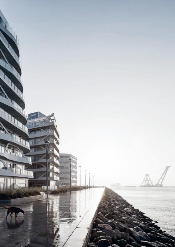
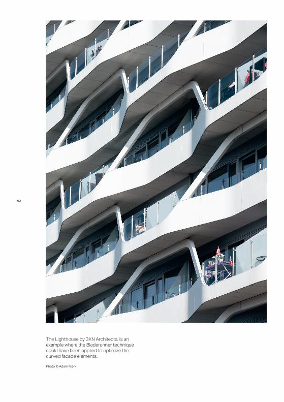
The Lighthouse by 3XN Architects, is an example where the Bladerunner technique could have been applied to optimize the curved facade elements.
Photo © Adam Mørk
6

R e t h i n k i n g t h e c o n s t r u c t i o n i n d u s t r y
Concrete is one of the world’s most advanced construction material with an annual global production of six billion cubic meters. According to Dansk Beton, the Danish concrete industry consumes 4.3 million cubic meters of concrete annually (9.6 million tons). In the Danish concrete industry, 75% of the revenue represents element and special production and 25% represents in-situ production. Furthermore, half of the new constructions in Denmark are non-standard productions and increasing demands for individual design makes the percentage even higher, according to the Danish Construction Association.
Bladerunner is a collaborative research project between the academics: Danish Technological Institute (DTI), DTU Compute and DTU Mechanical and the industry: Odico (robotics), Confac (concrete) and 3XN/GXN (architecture and innovation).
The vision of this project is to revolutionize the construction industry by facilitating the production of advanced organic formwork in architecture at price levels comparable to that of standard construction. It will offer an alternative to existing technologies that breaks away from the monotonous and expressionless concrete construction and opens up the possibility of modern and advanced construction.
Innovation Fund Denmark funds the research project, with a duration of three years. This booklet aims introduce the technologies, research findings and design demonstrations.
7

Workshop in Sydney at RobArch16 showing multiple object design pieces stacked together.
Photo © RobArch16
8

F l e x i b i l i t y c o m e s i n r o b o t i c c e l l s
Bladerunner will introduce the use of cutting-edge and innovative robotic cells for rapid production of non-standard concrete moulds in expanded polystyrene (EPS). The degree of architectonic projects with advanced geometry will rapidly upgrade both Danish and international construction standards and in return, the demand for technologies that can enhance the architect’s design without increasing the construction budget will grow.
Bladerunner also aims to promote flexibility in the concrete production; the production cell easily customizes itself into different shapes, sizes and materials through a modular software system for geometry calculations, tool handling, and robotic motion planning. The flexibility also facilitates in-situ production (i.e. being able to cut the formwork directly at the construction site).
I n t e r f a c e i n b e t w e e n
The commercial success of Bladerunner is dependent on its capability to demonstrate production over or on par with existing market quality in regards to geometric freedom, tolerance, surface smoothness and final application. The partners of this research project are linking the full cycle of research, innovation, implementation and production together and are creating a strong framework for geometric freedom, at the same time, dealing with robotic production constraints.
9
10
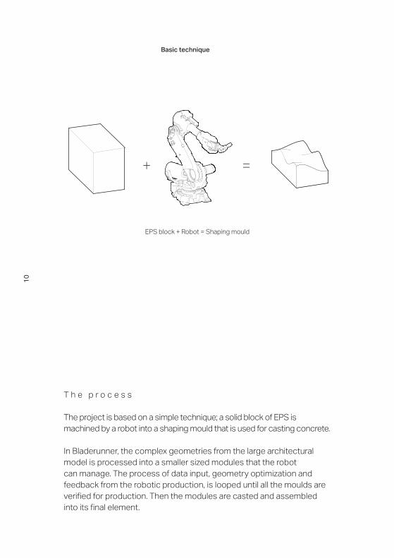
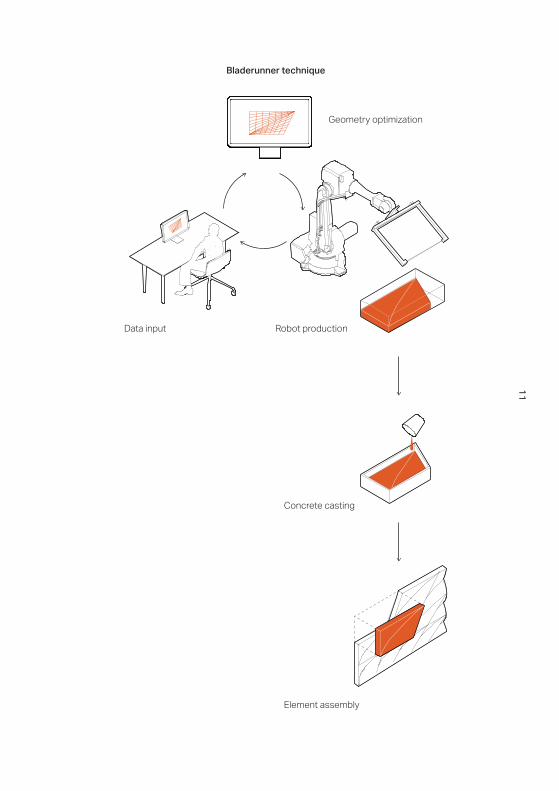
T h e p r o c e s s
The project is based on a simple technique; a solid block of EPS is machined by a robot into a shaping mould that is used for casting concrete.
In Bladerunner, the complex geometries from the large architectural model is processed into a smaller sized modules that the robot can manage. The process of data input, geometry optimization and feedback from the robotic production, is looped until all the moulds are verified for production. Then the modules are casted and assembled into its final element.
+ =
EPS block + Robot = Shaping mould
Basic technique
11
Data input
Geometry optimization
Robot production
Bladerunner technique
Concrete casting
Element assembly
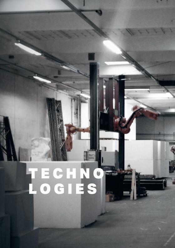
T E C H N OL O G I E S

M e t h o d s
Bladerunner addresses the demand for technologies that can enhance the design concept without increasing the construction budget, manufacturing time and compromise on the design geometry. Bladerunner produces moulds for the industry by replacing the traditional mould manufacturing process with robot technology and connecting the digital pipeline setup from designer to fabricator.
A Bladerunner cell consists of three robot-technologies: CNC-milling, hot-wire-cutting and hot-blade-cutting, each capable of producing unique geometrical subsets.
In combination, these technologies will facilitate the production of any given EPS block geometry.
14
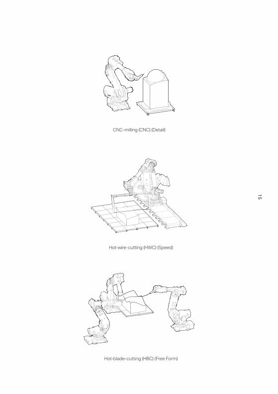
CNC-milling (CNC) (Detail)
Hot-wire-cutting (HWC) (Speed)
Hot-blade-cutting (HBC) (Free Form)
15
Speed
1 2 3 4 5
Detail
Advanced Geometry
Speed
1 2 3 4 5
Detail
Advanced Geometry
Speed
1 2 3 4 5
Detail
Advanced Geometry
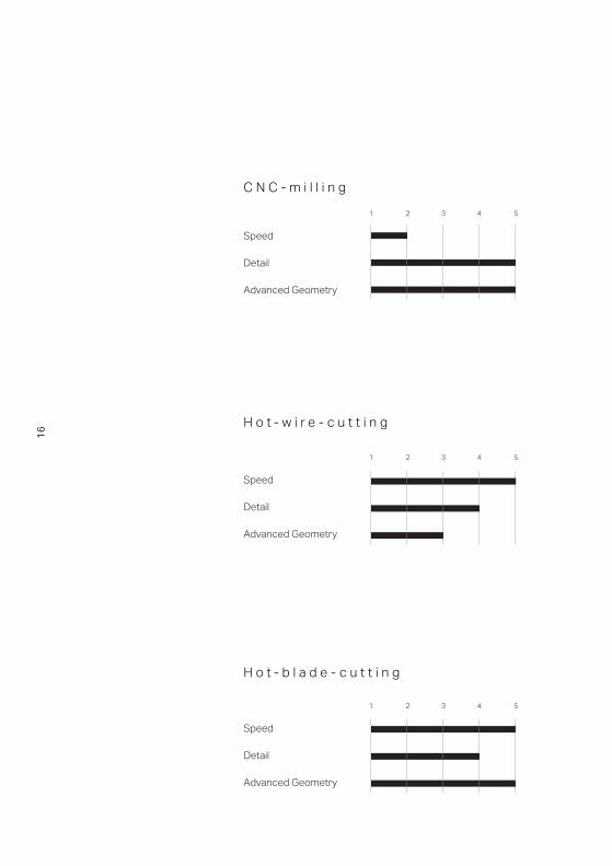
C N C - m i l l i n g
H o t - w i r e - c u t t i n g
H o t - b l a d e - c u t t i n g
Speed
Detail
Advanced Geometry
1 2 3 4 5
CNC-MILLING
Speed
Detail
Advanced Geometry
1 2 3 4 5
HOT-WIRE-CUTTING
Speed
Detail
Advanced Geometry
1 2 3 4 5
HOT-BLADE-CUTTING
16

141 50
354
420
6667
10
10
141 50
354
420
6667
10
10
141 50
354
420
6667
10
10
141 50
354
420
6667
10
10
141 50
354
420
6667
10
10
141 50
354
420
6667
10
10
Single curved surface
Double curved surface optimization needed
Highly detailed surface
17

CNC-milling removes material layer by layer from roughing in the beginning to a fine and detailed resolution and its flexibility adapts to spatial structures and surface design.
All photos © Odico
18
141 50
354
420
6667
10
10
141 50
354
420
6667
10
10
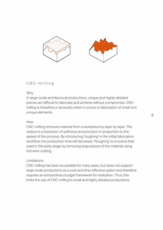
C N C - m i l l i n g
Why In large-scale architectural productions, unique and highly detailed pieces are difficult to fabricate and achieve without compromise. CNC-milling is therefore a necessity when it comes to fabrication of small and unique elements.
How CNC-milling removes material from a workpiece by layer by layer. The output is a resolution of softness and precision in proportion to the speed of the process. By introducing ‘roughing’ in the initial fabrication workflow, the production time will decrease. ‘Roughing’ is a routine that used in the early stage by removing large pieces of the material using hot-wire-cutting.
Limitations CNC-milling has been accessible for many years, but does not support large-scale productions as a cost and time-effective option and therefore requires an extraordinary budget framework for realization. Thus, this limits the use of CNC-milling to small and highly detailed productions.
19
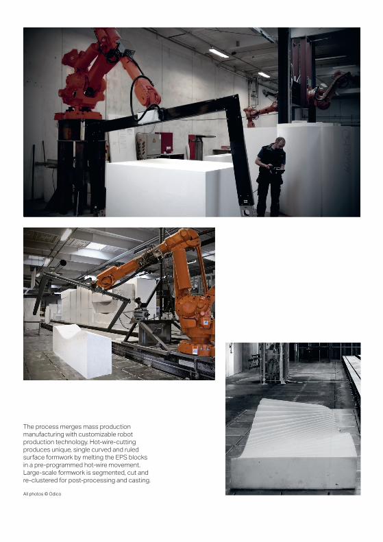
The process merges mass production manufacturing with customizable robot production technology. Hot-wire-cutting produces unique, single curved and ruled surface formwork by melting the EPS blocks in a pre-programmed hot-wire movement. Large-scale formwork is segmented, cut and re-clustered for post-processing and casting.
All photos © Odico
141 50
354
420
6667
10
10
141 50
354
420
6667
10
10
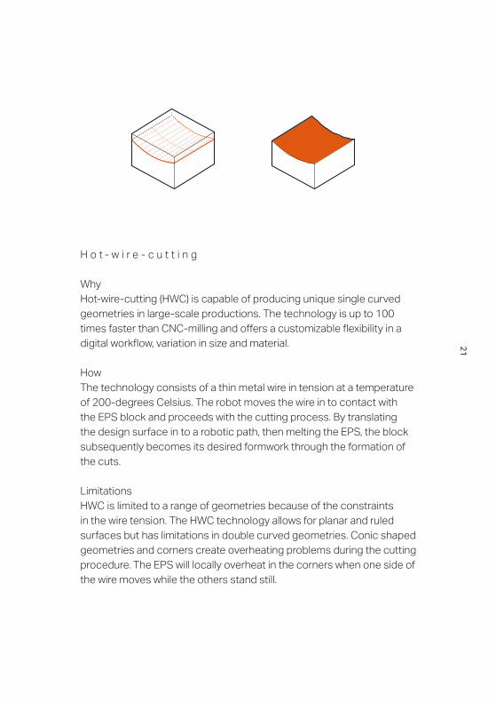
H o t - w i r e - c u t t i n g
WhyHot-wire-cutting (HWC) is capable of producing unique single curved geometries in large-scale productions. The technology is up to 100 times faster than CNC-milling and offers a customizable flexibility in a digital workflow, variation in size and material.
HowThe technology consists of a thin metal wire in tension at a temperature of 200-degrees Celsius. The robot moves the wire in to contact with the EPS block and proceeds with the cutting process. By translating the design surface in to a robotic path, then melting the EPS, the block subsequently becomes its desired formwork through the formation of the cuts.
LimitationsHWC is limited to a range of geometries because of the constraints in the wire tension. The HWC technology allows for planar and ruled surfaces but has limitations in double curved geometries. Conic shaped geometries and corners create overheating problems during the cutting procedure. The EPS will locally overheat in the corners when one side of the wire moves while the others stand still.
21

New technologies require evaluation and explorations from input to output ensuring a surface quality exact as the design input. A hot-blade-cutting setup consists of three robots producing double curved formwork. The heated blade is fixed between two robots controlling the bendability and flexibility while the third robot moves the EPS block in contact to the heated blade and controls the speed of the production. All photos © Odico
22
141 50
354
420
6667
10
10
141 50
354
420
6667
10
10
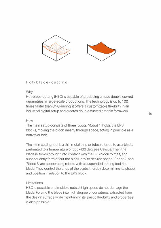
H o t - b l a d e - c u t t i n g
WhyHot-blade-cutting (HBC) is capable of producing unique double curved geometries in large-scale productions. The technology is up to 100 times faster than CNC-milling; it offers a customizable flexibility in an industrial digital setup and creates double curved organic formwork.
HowThe main setup consists of three robots. ‘Robot 1’ holds the EPS blocks, moving the block linearly through space, acting in principle as a conveyor belt.
The main cutting tool is a thin metal strip or tube, referred to as a blade, preheated to a temperature of 300-400 degrees Celsius. Then the blade is slowly brought into contact with the EPS block to melt, and subsequently form or cut the block into its desired shape. ‘Robot 2’ and ‘Robot 3’ are cooperating robots with a suspended cutting tool, the blade. They control the ends of the blade, thereby determining its shape and position in relation to the EPS block.
LimitationsHBC is possible and multiple cuts at high speed do not damage the blade. Forcing the blade into high degree of curvatures extracted from the design surface while maintaining its elastic flexibility and properties is also possible.
23

Hot w
ire c
uttin
gHo
t bla
de c
uttin
gCutting Techniques Tool Paths
Hot-wire-cutting (HWC ) and hot-blade-cutting (HBC) are technologies for large-scale manufacturing. They unlock a new and affordable pipeline of mass production of complex formwork.
All photos © Odico
H o t - w i r e - c u t t i n g v s . H o t - b l a d e - c u t t i n g
Curved path
CongruentmotionStraight rail
Curved railCongruent
motion
Focal pointmotion
Focal pointmotion
T
T
T
T
C
C
Curved path
24
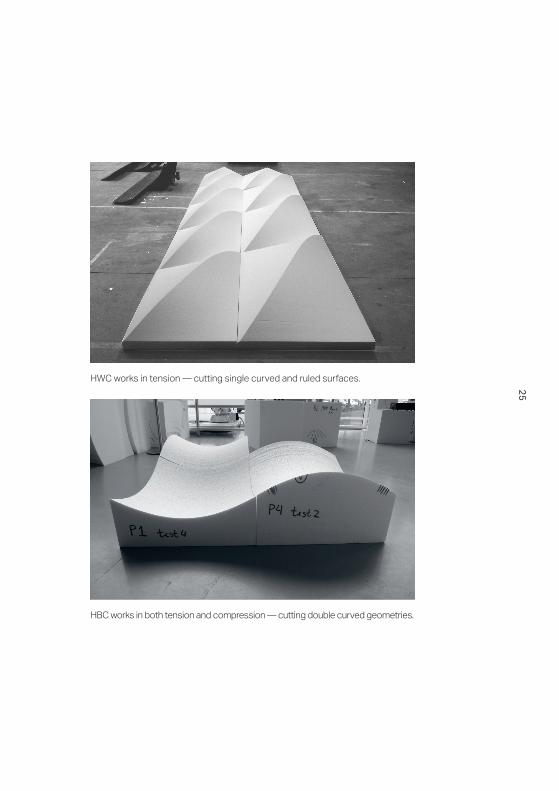
HWC works in tension — cutting single curved and ruled surfaces.
HBC works in both tension and compression — cutting double curved geometries.
H o t - w i r e - c u t t i n g v s . H o t - b l a d e - c u t t i n g
25
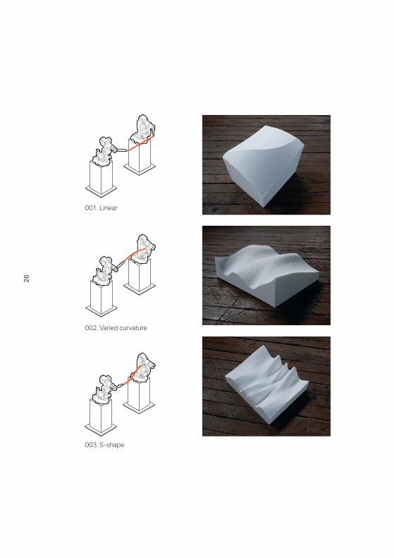
001. Linear
002. Varied curvature
003. S-shape
26

004. Pushing
005. Asymetrical
006. Rope skippingAll photos © RobArch16
27
28
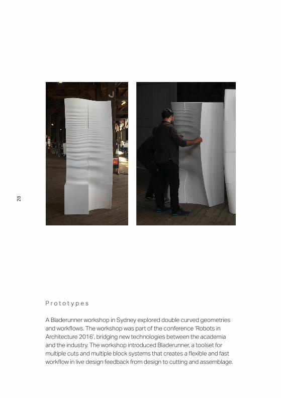
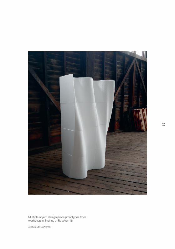
P r o t o t y p e s
A Bladerunner workshop in Sydney explored double curved geometries and workflows. The workshop was part of the conference ‘Robots in Architecture 2016’, bridging new technologies between the academia and the industry. The workshop introduced Bladerunner, a toolset for multiple cuts and multiple block systems that creates a flexible and fast workflow in live design feedback from design to cutting and assemblage.
29
Multiple object design piece prototypes from workshop in Sydney at RobArch16
All photos © RobArch16
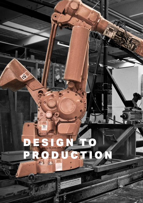
D E S I G N T O P R O D U C T I O N


001. Design
002. Rationalization
003. Cutting
004. Casting
005. Assembly
32
Diagram showing workflow in five steps:Design, Rationalization, Cutting, Casting, Assembly
W o r k f l o w
Bladerunner is a collaborative effort between architects, engineers and mathematicians that digitize the entire workflow from design to production. The overall workflow links conventional digital drawing tools with robotic technologies and standard concrete casting techniques.
The workflow consists of five key steps: Design, Rationalization, Cutting, Casting and Assembly. They all interconnect and make arbitrary design input in a fast and cost-effective process. Each step contain a huge amount of data and know-how that informs and loops around to ensure the best output possible. The workflow allows for multiple iterations between designer and fabricator to establish a clear work path from digital rationalization to physical representation.
The rationalization process converts an arbitrary design surface in to hot-blade-cutting geometry. This requires the identification of technologies and rationalization of geometry (CNC-milling, hot-wire-cutting or/and hot-blade-cutting) before rebuilding the geometry to the accuracy of the robot-motion, EPS-segmentations and tolerances.
33

W o r k f l o w b r e a k d o w n
Rethinking mass production for a unique and double curved formwork in a refined setup from design to assembly. The setup is generic; it is able to adapt to flexible inputs and generates a dialogue between clients and fabricators.
Setup configurations consists of five main steps: Design, Rationalization, Cutting, Casting and Assembly. They communicate through a digital and physical pipeline database with integrated loops to ensure a smooth transition from digital file to physical behaviour.
Workflow deviations from digital pipelines to physical productions inform the process and minimizes the complications in assembly mode.
34

Rationalization
digital file digital file formwork concrete
Design Cutting Casting Assembly
max. deviation from original geometry
adjustement during assembly
target tolerance
Rationalization
digital file digital file formwork concrete
Design Cutting Casting Assembly
max. deviation from original geometry
adjustement during assembly
target tolerance
Design Rationalization Cutting Casting Assembly
digital file digital file formwork concrete
Setupconfigurations
Setupconfigurations
Workflowdeviations
Diagram showing setup configurations and workflow deviations
35

Design Rationalization Cutting AssemblyCasting
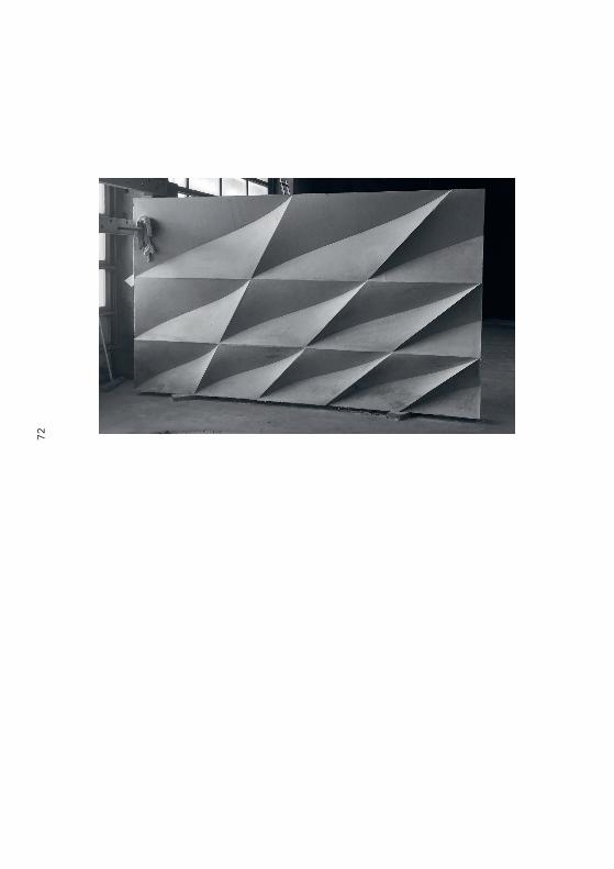
D e s i g n d e m o n s t r a t o r
By scaling up and analyzing the full-size panels, the design demonstrator represents a novelty within the production of large-scale double curved formwork. The design panel demonstrates the workflow from design to production and links digital techniques with the manufacturing industry.
36
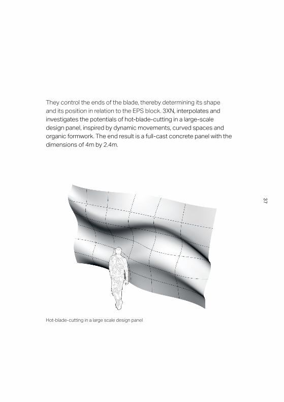
Hot-blade-cutting in a large scale design panel
They control the ends of the blade, thereby determining its shape and its position in relation to the EPS block. 3XN, interpolates and investigates the potentials of hot-blade-cutting in a large-scale design panel, inspired by dynamic movements, curved spaces and organic formwork. The end result is a full-cast concrete panel with the dimensions of 4m by 2.4m.
37
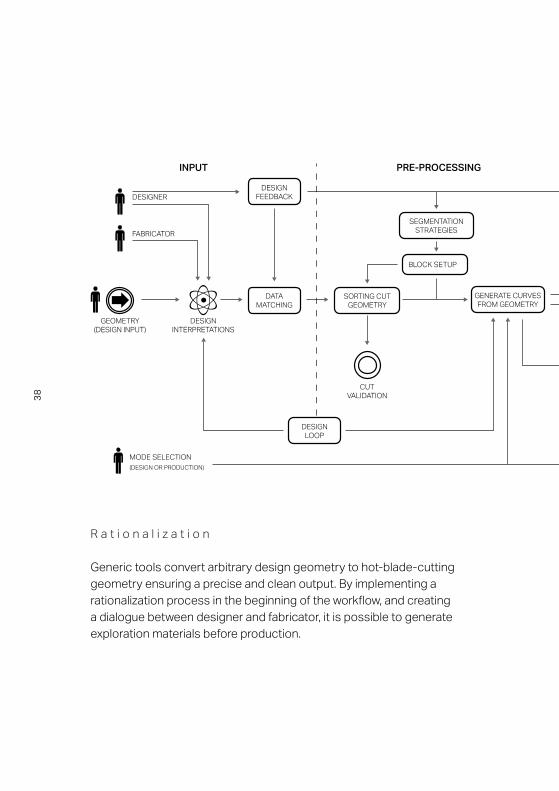
R a t i o n a l i z a t i o n
Generic tools convert arbitrary design geometry to hot-blade-cutting geometry ensuring a precise and clean output. By implementing a rationalization process in the beginning of the workflow, and creating a dialogue between designer and fabricator, it is possible to generate exploration materials before production.
USER INPUT
DECISIONPOINT
INTERMEDIATE RESULT
DATASET
DIGITALPROCESS
OUTPUTSTART
DATA EXPORT OF RATIONALIZATION
REPRESENTATION OF RATIONALIZATION
(GEOMETRY)
CALCULATE CURVE LENGTH
PRE-PROCESSINGGeometry to Data
CONVERTING OUTPUTINPUT
DESIGNER
FABRICATOR
GEOMETRY(DESIGN INPUT)
DESIGNINTERPRETATIONS
DATA MATCHING
DESIGNLOOP
DESIGNFEEDBACK
SORTING CUT GEOMETRY
GENERATE CURVES FROM GEOMETRY
EXPORT:DATA
GEOMETRYELASTICA
APPROXIMATION
SEGMENTATIONSTRATEGIES
CUT VALIDATION
BLOCK SETUP
MODE SELECTION(DESIGN OR PRODUCTION)
EXTRACT START-POINT &
VECTOR
EXTRACT END-POINT &
VECTOR
38

USER INPUT
DECISIONPOINT
INTERMEDIATE RESULT
DATASET
DIGITALPROCESS
OUTPUTSTART
DATA EXPORT OF RATIONALIZATION
REPRESENTATION OF RATIONALIZATION
(GEOMETRY)
CALCULATE CURVE LENGTH
PRE-PROCESSINGGeometry to Data
CONVERTING OUTPUTINPUT
DESIGNER
FABRICATOR
GEOMETRY(DESIGN INPUT)
DESIGNINTERPRETATIONS
DATA MATCHING
DESIGNLOOP
DESIGNFEEDBACK
SORTING CUT GEOMETRY
GENERATE CURVES FROM GEOMETRY
EXPORT:DATA
GEOMETRYELASTICA
APPROXIMATION
SEGMENTATIONSTRATEGIES
CUT VALIDATION
BLOCK SETUP
MODE SELECTION(DESIGN OR PRODUCTION)
EXTRACT START-POINT &
VECTOR
EXTRACT END-POINT &
VECTOR
39
Original Input Surface
Original Input Surface
Design Rationalization Cutting AssemblyCasting
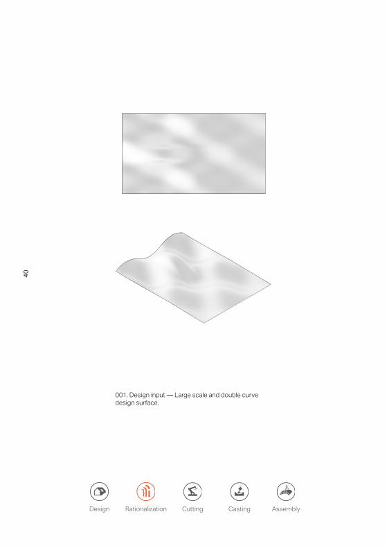
001. Design input — Large scale and double curve design surface.
40
Rationalization and Cut Direction
Rationalization and Cut Direction
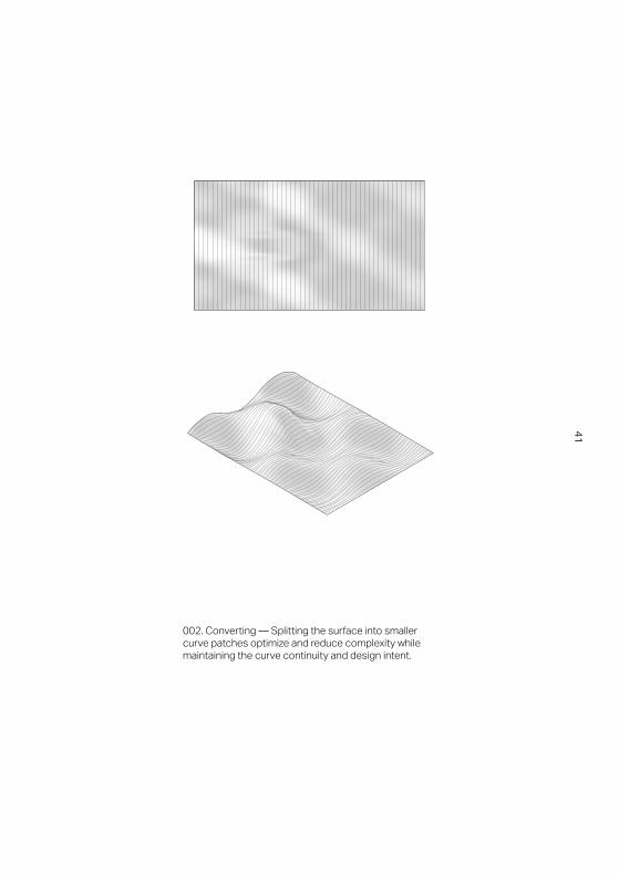
002. Converting — Splitting the surface into smaller curve patches optimize and reduce complexity while maintaining the curve continuity and design intent.
41

Re-Configured Surface from Rationalization and segmentation
Re-Configured Surface from Rationalization and segmentation
Design Rationalization Cutting AssemblyCasting
003. Segmentation — A dialogue between designer and fabricator regarding the visual appearance, material behavior and robot motion defines the segmentation and quality output of the design intent.
42
Output Geometry in Segments
Output Geometry in Segments
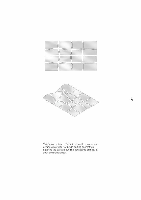
004. Design output — Optimized double curve design surface is split in to hot-blade-cutting geometries matching the overall bounding constraints of the EPS block and blade length.
43

p0, t0
p1, t1
002. Elastica Curves (Generating cutting-domain) Data: Start and End points, Start and End tangents, length
Design domain
Hot-blade-cutting domain
001. Design domain and Hot-blade-cutting domain
Design Rationalization Cutting AssemblyCasting
C u t t i n g — r o b o t m o t i o n
The design domain defines each EPS block boundary and analyses the complexity, resolution of design and sizing of the segmentation. The rationalization and preparation to hot-blade geometries take into account the fixed blade between two robots, enabling us to choose the location and rotation of the ends of the blade. It approximates the physical behavior of the blade and reproduces Euler-Elastica curves while maintaining the curvature continuity between segmentations to preserve the smoothness of the design.
44
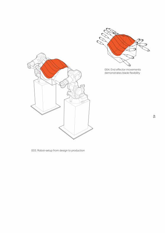
004. End effector movements demonstrates blade flexibility
003. Robot-setup from design to production
45

Design Rationalization Cutting AssemblyCasting
46

Pre-assembly — An identification system map each block, position and direction, which makes a quick assembly and fast evaluation process possible. Each block is quality checked locally and globally to ensure smooth transitions between blocks and for high degree of surface quality.
All photos © Odico
47
Design Rationalization Cutting AssemblyCasting
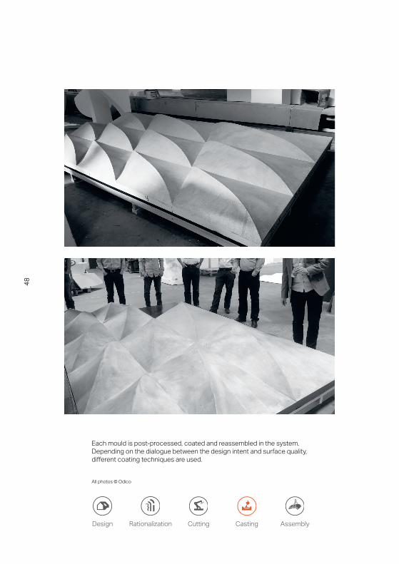
Each mould is post-processed, coated and reassembled in the system. Depending on the dialogue between the design intent and surface quality, different coating techniques are used.
All photos © Odico
48
Design Rationalization Cutting AssemblyCasting
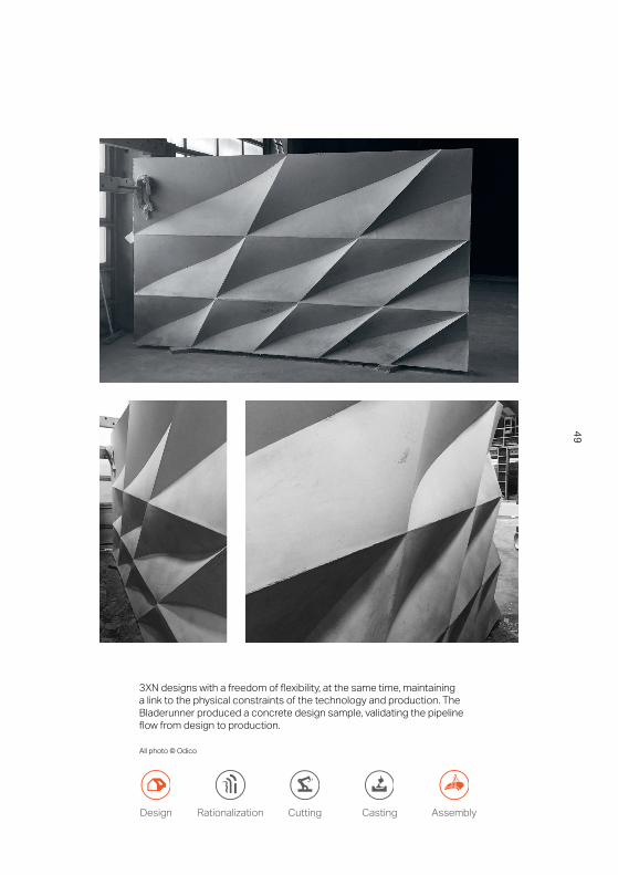
3XN designs with a freedom of flexibility, at the same time, maintaining a link to the physical constraints of the technology and production. The Bladerunner produced a concrete design sample, validating the pipeline flow from design to production.
All photo © Odico
49

G R O V E T O W E R SM U M B A I

D E S I G N T O P R O D U C T I O N
G R O V E T O W E R SM U M B A I
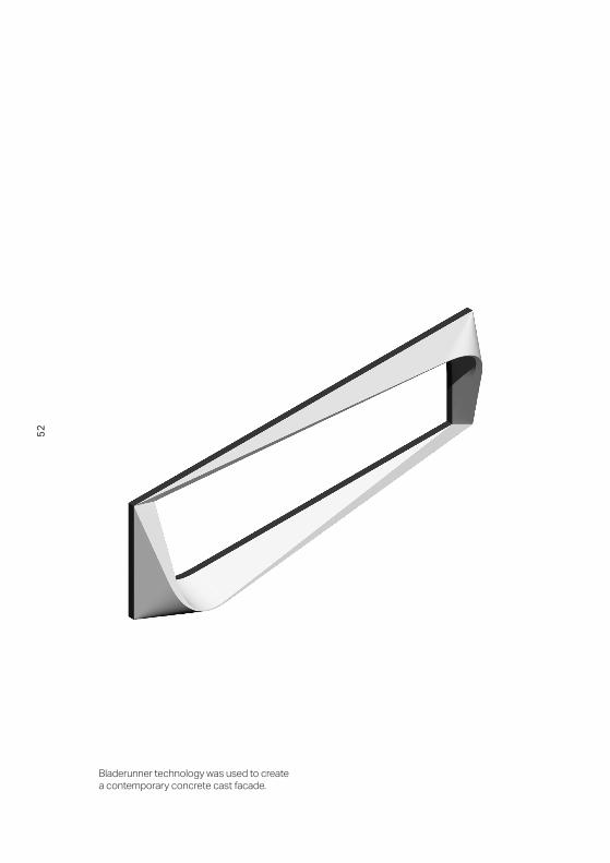
Bladerunner technology was used to create a contemporary concrete cast facade.
52

I n d i v i d u a l m a s s p r o d u c t i o n
The Grove Towers is a mixed-used development located in Mumbai designed by 3XN in 2013. A challenging aspect of this project was the complex facade; each facade element varied as it rose towards the sky to optimize solar shading. With the use of Bladerunner technology, off-site fabrications methods was possible to make the moulds for the concrete as well as in-situ casting method, which can ensure the quality of the design, reduced cost and still involve the local economy.
E n v i s i o n i n g t h e f u t u r e
With the help of contemporary concrete casting practice, the variation of the facade elements would be greatly reduced to a level that is cost-effective for mass production. In the design, there were 1800 unique moulds but after optimization, there are now 600 unique moulds. This case study explores the implementation of the innovative robotic cell production of concrete formwork. The ambition of the Bladerunner project is to break through the current constraints of construction, as exhibited through Grove Towers, and to give greater freedom to architects so that design can be realized as intended.
53

001. Facade panel framing an apartment unit on tower two has dimensions of 3.5m x 12m. One facade panel consists of a top and bottom frame that merge together at the diagonal corners.
002. Optimizing the amount, sizes and arrangement of EPS-blocks for one facade panel.
54
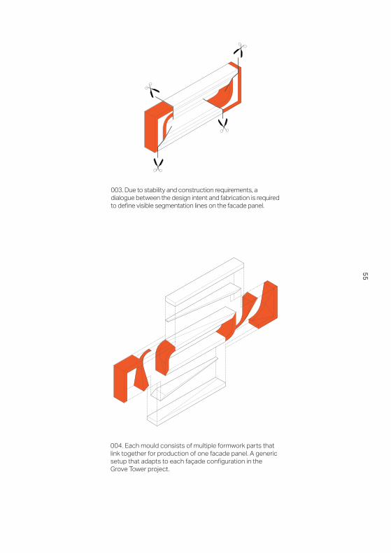
003. Due to stability and construction requirements, a dialogue between the design intent and fabrication is required to define visible segmentation lines on the facade panel.
004. Each mould consists of multiple formwork parts that link together for production of one facade panel. A generic setup that adapts to each façade configuration in the Grove Tower project.
55
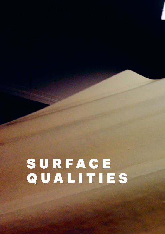
S U R F A C EQ U A L I T I E S
S U R F A C EQ U A L I T I E S

Multiple formwork brought together in one single form
All photos © Odico

I n t r o d u c t i o n
Design surfaces, rationalized surfaces and casted surfaces are all part of the Bladerunner workflow from input to output. All surface types are main catalysts in the dialog between client and manufacture and they represent key steps in the production of moulds. Depending on the function of a surface, visible or non-visible design geometry, the price, speed and coating technique differs. An internal surface, hidden in the construction, have low requirements regarding surface quality while visible façade panels, covering the building, have higher surface quality demands.
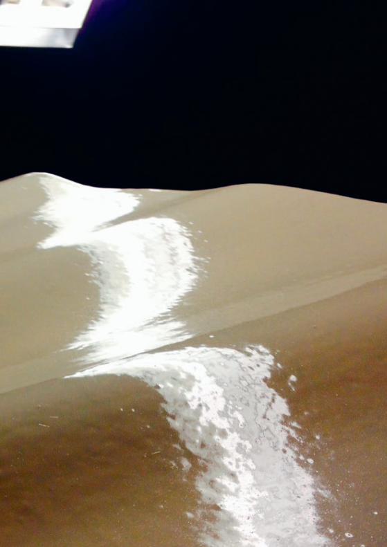
Each mould is cut in polystyrene, a fragile material that easily gets deformed in a production line or at the building site. By pre-processing the moulds with a layer of folio or spray coating, inaccuracy in the surface can be circumvented.
The final expression in the surface depends on the detail and design intentions from the client and the function of the surface. Different coating techniques equals different surface qualities, from coarse to smooth and shiny polished surface finishes.
E x p l o r a t i o n s
Surface quality is a result of cutting precision, mould assembly, coating techniques, subsequent tolerances, connections and surfaces. To ensure a full compatibility, a library of pilot productions and toolmaking has been developed.
59

Hot-wire-cutting and hot-blade-cutting
All photos © Odico
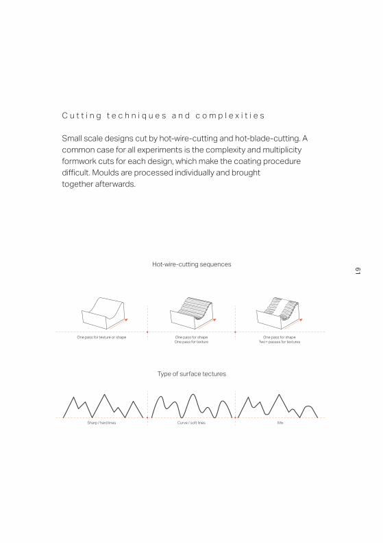
Hot-wire-cutting sequences
Sharp / hard lines Curve / soft lines Mix
One pass for texture or shape One pass for shapeOne pass for texture
One pass for shapeTwo+ passes for textures
Type of surface tectures
C u t t i n g t e c h n i q u e s a n d c o m p l e x i t i e s
Small scale designs cut by hot-wire-cutting and hot-blade-cutting. A common case for all experiments is the complexity and multiplicity formwork cuts for each design, which make the coating procedure difficult. Moulds are processed individually and broughttogether afterwards.
Sharp / hard lines Curve / soft lines Mix
One pass for texture or shape One pass for shapeOne pass for texture
One pass for shapeTwo+ passes for textures
61

Panel processed and coated
All photos © Odico
P a n e l d e s i g n
The final expression in the surface depends on the detail and design intention from the client and the function of the surface. Different coating techniques equals different surface qualities, from coarse to smooth and shiny polished surface finishes.
62

63

Surface treatment and coating
All photos © Odico
C o a t i n g o n c o m p l e x s u r f a c e s
Investigations in flexible spray coating applications for double curved and highly textured geometries. Spray coating offer an alternative to folio coating when curvatures are complex and detailed, but have limitations in the manual application process because it dries fast and can spray in an uneven layer thickness.
64

65

Distinct
PANEL TO PANEL TRANSITION
Local element in a global configuration. Shape sub-divided in to local elements.Fluid
SEGMENTATION
Equal Panel LayoutVarious panel sizes can be used to develop an overall facade
pattern/expression.
Various Panel Layout
S e g m e n t a t i o n
Equal panel layout Various panel layoutVarious panel sizes can be used to develop
an overall facade pattern / expression
FluidShape sub-divided in
to local elements
DistinctLocal element in a
global configurattion
P a n e l t o p a n e l t r a n s i t i o n
66

Curved surface on panel
All photos © RobArch
67

O U T P U T

O U T P U T

Casted surface
All photos © Odico
70
O u t p u t
In 2012, the Bladerunner project initiated to develop a new manufacturing process, which targets the cost-effective production of double curved formwork. Developments in architectural robotics and digital manufacturing have seen the emergence of a number of approaches with the purpose of realizing structures of more advanced architectural geometries.
The technique developed in this effort, dubbed robotic hot-blade-cutting (HBC), deploys a multiple robotic process moving a flexible heated blade through expanded polystyrene (EPS) blocks in a thermal cutting process. A novel idea of robotic fabrication that enables a direct design to production workflow of double curved formwork.Pilot production experiments developed by Bladerunner research partners demonstrate the potential and applicability for production of pre-fabricated concrete elements. Used in combination with existing pre-fabricated and in-situ workflows, it ensures a full compatibility and a low barrier to adoption with established industry setups.
Bladerunner inputs arbitrary surfaces and translate them in to hot-blade geometries by using a top-down rationalization and digital process. Methods developed by Bladerunner research partners and implemented as prototype design tools enable interaction with non-specialist designers. The result of experimentations point to the perspective of a highly time-efficient production method from the digital workflow pipeline to the robotic hot-blade-cutting setup generating foam moulds.
71
72
Bladerunner links academia and industry together with specialists from each field, sharing and gaining knowledge, to rethink the construction industry from digital surface input to physical surface output. By linking hands-on knowledge, the implementation of physical constraints are applied in the digital pipeline and digitally optimized surfaces are applied in the final design output.
In contemporary architectural practice, a rising number of projects deploy advanced formwork and incorporates digital design tools and manufacturing techniques for realization. Bladerunner is novel for mass production of unique elements and by being fast, flexible and cost-efficient, Bladerunner will facilitate the production of double curved formwork in the future.
73

The project is supported by Innovation Fund Denmark

P r o j e c t p a r t n e r s
3XN Architects and GXN Innovation Kasper Guldager Jensen, Kenn Clausen, Morten Norman Lund, Steffen Riegas, Jingxian Xu, Rasmus Skov, Monika Wiecek, Alice Song, Albert Wang, Matthew Lawson, Hali Larsen, Dagmara Piszcz, Peter Villemoes, Aleksander Guldager Kongshaug, Allison Jang, Casper Østergaard Christensen.
ODICO Formwork RoboticsHenrik Winther Knudsen, Carina Pedersen, Anders Bundsgaard, Asbjørn Søndergaard, Jelle Feringa, Per Madsen, Henrik Bang, Tony Boyd.
Danish Technological InstituteJacob Kortbek, Kurt Nielsen, Lars Knudsen, Kurt Bo Genefke, Niels Korsager, Martin Mølbach Olsen, Rolf Green, Rasmus Busk Sørensen, Lasse Engberg Andersen, Mikkel Johansen, Troels Jørgensen, Asbjørn Stjernegård Harder.
DTU ComputeJens Graversen, Kasper Steenstrup, Toke Nørbjerg, David Brander, Andreas Bærentzen, Steen Markvorsen, Peter Nørtoft, Anton Evgrafov.
DTU MechanicsJesper Hattel, Kiril Plamenov Petkov.
CONFACErling Holm, Verner Lind, Frank Laursen, Peter Adamsen.

PrintPrinted in Denmarkby KLS PurePrint
This book is printedon paper with Nordic Ecolabel and complies with FSC standards
1. edition, 1. print 2016
ISBN978-87-998670-5-9


B L A D E R U N N E R R o b o t s i n a r c h i t e c t u r e