black hole imager: what happens at the edge of a ... - nasa · black hole imager: what happens at...
TRANSCRIPT

Black Hole Imager: What Happens at the Edge of a Black Hole?
Keith Gendreau (NASA/GSFC) Zaven Arzoumanian (USRA and NASA/GSFC) Webster Cash (University of Colorado) Paul Gorenstein (SAO) John Krizmanic (USRA and NASA/GSFC) Jesse Leitner (NASA/GSFC) Gerry Skinner (UMCP and NASA/GSFC) David Windt (RXO) Primary Contact: Keith Gendreau Code 662 NASA/GSFC Greenbelt, MD 20771 [email protected] 301-286-6188

Black Hole Imager: What Happens at the Edge of a Black Hole?
1
Summary Black Hole Imager (BHI) is a mission to reveal details of the tortured space-time
around supermassive Black Holes (SMBHs) through X-ray and γ-ray imaging with spatial resolution on event-horizon scales. Here, we outline the basic science case for such a mission, describe the current status of the technologies involved, and discuss activities that must take place in the coming decade in order to realize BHI by 2030.
A Black Hole (BH) represents the ultimate end point of matter and harbors the most extreme gravitational environment in the universe. While BHs are predicted in the formulation of General Relativity (GR), some of the strongest evidence for their existence, based on X-ray spectroscopy and timing data interpreted through models based on GR, remains indirect. Moreover, these models are not unique, as the data come from integrated regions very large compared to the expected size of the event horizons. The largest SMBH event horizons should subtend a few µarcseconds (µas) and are expected to be surrounded by accretion disks, relativistic jets, and clouds of ionized and partially ionized matter, all contained within the smallest features resolvable by the sharpest imagers available today. Only high angular resolution imaging will unambiguously untangle this complex environment.
Sub-millimeter/radio interferometry will very likely just resolve the event horizon of the SMBH at the center of our Milky Way within the next decade[1]. An X-ray/γ-ray BHI will greatly expand on this work by: 1) providing 100 times finer angular resolution, 2) using imaging spectroscopy to map the Kerr metric describing the space-time around the BH and thus more fully validate GR in the strong gravity limit, and 3) making available many more target SMBHs. That the immediate vicinities of many SMBH event horizons are X-ray/γ-ray bright suggest an exciting science return from BHI.
In the coming decade, the International X-ray Observatory (IXO) will provide deep integrated-flux spectroscopy and timing on BH candidates, and the Laser Interferometer Space Antenna (LISA) will “hear” the ringing of space-time as BHs merge. BHI will complete the picture by “seeing” the detailed structure of the BH environment.
In the last National Academy decadal report on astrophysics and astronomy, it was recommended that X-ray interferometry be explored as a method to open up this science. Since that time, fundamental laboratory demonstrations of broadband X-ray interferometers adaptable to a BHI have been achieved, and the use of diffractive optics to realize diffraction-limited angular resolution in the hard X-ray/γ-ray bands has also been demonstrated. Members of our team have performed initial mission formulations involving these technologies.
Our goals for the coming decade are to continue the advancement of the core technologies involved so that BHI may be realized before 2030. This involves advancing the technology readiness levels (TRLs) of optical components as well as critical supporting technologies. We will outline three approaches that are actively being pursued for the optical components to BHI. The critical supporting technologies are formation flying and a method to point BHI stably toward a SMBH target.
While we are working toward the goal of an X-ray/γ-ray imaging spectrometer with better than 1 µas angular resolution to resolve SMBH event horizons, it is important to keep in mind that there is a tremendous discovery space available on the road to such an instrument. Technology developments toward a BHI in the next decade will give us the opportunity to unveil this high resolution universe.

Black Hole Imager: What Happens at the Edge of a Black Hole?
2
1. Key Science Goals Scientists and lay people alike are intrigued by black holes. To the scientist, they
provide the ultimate test of Einstein's theory of General Relativity (GR) and underlie exotic phenomena such as particle jets moving at nearly light speed. To the public, black holes are mysterious points of no return that capture the imagination. Both views reflect a fascination with the question: What happens at the edge of a black hole?
This question has fundamental physics aspects as well as connections to questions of the structure and evolution of galaxies. In particular, supermassive black holes have become an essential part of the model of how galaxies form and evolve. It is important to confirm our belief that they actually exist and to understand the role that energetically active BHs play in the centers of Active Galactic Nuclei (AGN).
GR has been validated in many different ways in the weak gravity limit and must be accounted for to understand much of what we see in the universe. GR is important even on terrestrial scales (e.g., the Global Positioning System) in our ordinary world. However, Black Holes (BHs) are not ordinary objects in the universe. They are the endpoint of matter and possess the deepest gravitational potentials known. Is GR as we understand it today valid in the strong gravity environment of BHs?
We need to understand not just BHs themselves, but how they influence their environment. We know that an accretion disk feeds the BH in an AGN while relativistic jets stream matter and energy away. A gaseous torus and other structures complicate the message that we receive when we look at the integrated flux from the region, and the details remain unknown. How is energy released from the accretion disk? How are the relativistic jets of AGN formed? What is the role of BH spin? In summary: What is the detailed anatomy of an AGN?
In our Astro2010 science white paper [2] we showed that combining sub-µas resolution X-ray imaging and spectroscopy directly addresses the question: “What happens at the edge of a black hole?” by 1) measuring the warping of space-time near event horizons, 2) mapping matter and radiation flows in the vicinity of BHs, and 3) establishing the origin of relativistic BH jets (Fig. 1). These scientific themes are briefly reviewed below.
The leap in angular resolution needed to realize a BHI, 2–3 orders of magnitude over the current radio-interferometry capability, and six orders of magnitude beyond the state of the art in X-rays, appears daunting. Indeed, significant technological hurdles must be overcome (Sec. 3), but as the histories of optical and especially radio astronomy demonstrate, diffraction-limited and interferometric imaging capabilities need not lag far
Figure 1. Science potential of ultra high angular resolution imaging.

Black Hole Imager: What Happens at the Edge of a Black Hole?
3
behind the initial opening of spectral windows. Considering how much we have learned in the 400 years since Galileo’s first telescope, and the 75 years since the advent of radio astronomy, the development of a high-resolution X-ray Black Hole Imager (BHI) will, no doubt, reveal a much more intricate universe than we can imagine now. Many of the science white papers submitted to the Astro2010 committees discuss the tremendous new discovery potential of high angular resolution astronomy; in Sec. 1.3 we briefly touch upon the role of high-resolution X-ray imaging in the unveiling of this discovery space.
1.1 Black Hole Science Is GR valid in the strong gravity limit?
Most of what we currently know about gravity comes from where gravity is weak. Testing GR in the strong field limit can only be done in the intense gravity field near a BH event horizon. We know that these regions are, in many cases, X-ray bright. Timing and spectral observations have so far been consistent with GR[3] (e.g., Fig. 2), but the clutter of matter and energy in data integrated over the entire emitting region complicates their interpretation. High spatial resolution X-ray imaging and spectroscopy are needed.
By tracing the motion of matter falling into a BH, a high-resolution imager can map the geometry of space-time near the event horizon. IXO and LISA will make the first quantitative measurements capable of confirming or refuting the Kerr nature of BH space-times. BHI will complement these studies and take them to a new level.
Imaging spectroscopy with spatial resolution of order one gravitational radius (rg = GM/c2 subtends M8/D µas, where M8 is BH mass in units of 108 Msun and D is distance in Mpc—see Table 1 below) will allow direct mapping of the gravitational and Doppler redshifts/blueshifts across the accretion disk. Comparing observed and calculated “redshift maps” gives a powerful and quantitative test of strong-field GR and the Kerr metric in the absence of significant gravitational radiation. In the time frame of BHI, detailed and physically realistic computer simulations of relativistic accretion disks will be available for comparison with observed redshift maps[4]. A complementary approach to spectroscopy is provided by polarimetry. The X-ray continuum from accretion disk coronae is likely to be significantly polarized, and GR governs how polarization vectors are rotated as photons propagate through the Kerr metric. Detailed polarization maps could be even more powerful than imaging spectroscopy for testing GR[5].
Event horizons are expected to cast a “shadow” where emissions from the far-side flow fall into the BH. GR makes clear predictions about the apparent shadow diameter (Table
Figure 2. (Left) Fe K line emission from NGC 3516 as a function of energy and time, as seen with XMM-Newton. Pixel size is 2 ks ×100 eV. (Right) Theoretical time-energy map for a coronal flare at 9 rg and disk inclination of 20°, in reasonable agreement with the observed emission[3].

Black Hole Imager: What Happens at the Edge of a Black Hole?
4
1), a factor of ~2 greater than values predicted in the absence of light bending—strong GR effects act as a lens magnifying the shadow image. GR also predicts that the shadow will appear off center and slightly non-circular if the BH is spinning appreciably. The precise shape of the shadow thus probes the Kerr metric[6].
Models and techniques that are used to investigate BHs and AGN, such as Fe K line broadening and reverberation mapping[7], will continue to be refined and even produce qualitatively improved understanding as new observing capabilities, such as IXO, become available. But interpretation of the data will continue to rely on assumptions about the unseen innermost environment of BHs, and be subject to poorly-constrained systematics (e.g., disk inclination). With high spatial resolution imaging, these uncertainties can be virtually eliminated and the models validated. What is the anatomy of an AGN?
Direct imaging of a SMBH on µas scales will lay bare the structures and processes that power Active Galactic Nuclei (AGN).
Currently, we probe the anatomy of AGN by constraining models to match the spectral and timing properties of emissions spatially integrated over many complex phenomena (Fig. 3). This method is unsatisfactory because completely different models are still allowed. All that is missing is the high imaging resolution required to separate the component structures. The X-ray band is ideally suited to this purpose: continuum and, in many cases, characteristic-line X-ray emission appears to be a generic feature of BH accretion, often carrying with it signatures of the absorbing and ionized structures.
The energy sources that underlie BH emissions are gravitational potential energy, which powers accretion, and the rotational energy of the BH, which—in some models—drives jet formation. The physical mechanisms at work are imprecisely understood, but they act most vigorously where gravitational and electromagnetic fields are most intense, near the BH event horizon. Imaging on these scales promises to revolutionize our understanding of these fundamental processes.
Accretion flows are common throughout astrophysics. Two modes, radiatively efficient and inefficient, appear to encompass the observational parameter space in BH systems. Radiatively efficient accretion disks, probably present in Seyfert nuclei and other luminous AGN, emit X-rays through thermal Comptonization in a disk-corona.[9]
Low-luminosity galactic nuclei (e.g., Sgr A* and M87) seem to operate instead in a radiatively inefficient mode[10][11] in which much of the accretion power is trapped in the very hot and quasi-spherical accretion flow, and bremsstrahlung and Comptonization produce X-rays. High-resolution continuum X-ray images of these flows, once gravitational light-bending is taken into consideration, will reveal where and how accretion energy is released. For example, the location and geometry of the X-ray-emitting corona can be determined: is it a disk-hugging or geometrically thick structure, and how patchy is it? Temporal evolution is also important, as rapid (minutes to hours) and large-amplitude X-ray variability is a
Figure 3. Illustration of an AGN[8]. (Urry & Padovani 1995.)

Black Hole Imager: What Happens at the Edge of a Black Hole?
5
widespread property of AGN, and of fundamental relevance to accretion physics. With sufficient sensitivity, individual flaring regions can be identified and tracked, exposing the accretion flow as it crosses the radius of marginal stability, providing vital clues to the impulsive and violent physics at play.
An important prediction of BH astrophysics theory is that BH rotational energy is extractable via the action of magnetic fields[12]—a leading contender for the basis of relativistic jet production. Jets are already known to extend closer to the event horizon than the current milliarcsecond limits of radio VLBI images. Chandra X-ray Observatory imaging has demonstrated that jets emit X-rays at least down to kpc scales[13]. Variability arguments and X-ray production mechanisms that require strong magnetic fields and high ambient radiation density imply that much smaller scales are involved. High resolution X-ray imaging can therefore provide a unique view of the electrodynamics of jet formation in BH magnetospheres.
Finally, BHI can elucidate the acceleration mechanisms of AGN which have been correlated[14] to the arrival directions of ultra-high energy cosmic rays, rare particles with observed energies exceeding 1019 eV. Natural and powerful particle accelerators, perhaps energized by BH spin, may be formed within the innermost accretion flow or as a byproduct of relativistic jet formation.
1.2. Key Science Requirements Table 1 lists example SMBHs with current mass and distance estimates. Angular
resolution of order 1 µas puts exciting BH science within reach for at least five known objects. Achieving 0.05 µas brings many more objects into consideration. The Galactic Center and nearby elliptical galaxies are radiatively inefficient accretors and excellent candidates for observing the event horizon shadow. The Seyfert galaxies present smaller apparent event horizon sizes but allow the most constraining tests of GR to be performed.
Our current understanding of BH systems informs a set of requirements, the capabilities needed to address the science questions described above. We can anticipate, for example, that a BHI should have 1) angular resolution fine enough to resolve the gravitational radius of a SMBH, 2) sufficient collecting area, spectral bandpass, and energy resolution to perform imaging spectroscopy of known line features; and 3) a sufficiently wide field of view, or the ability to reconfigure baselines, so as to capture the different sizes of BH event horizons and jet forming regions.
BHI was developed as part of NASA’s Beyond Einstein Program. The science objectives for BHI in that program are in line with what we describe here. Table 2 shows a top-level science flowdown developed from these efforts. It is worth noting, however, that much new knowledge will be provided by missions (e.g., IXO and possibly X-ray polarimetry, such as GEMS) that will fly before a full-fledged BHI is undertaken; as a result, the requirements spelled out above should be considered a snapshot representing our current knowledge. At a later date, a different set of requirements motivated by a
Target
Mass
(108
Msun)
Distance
(Mpc)
!h
(µas)
log
(M/Medd)
Galactic Center 0.04 0.008 50 -10.3
M87 32 19.5 16.4 -5.8
NGC 4649 20 16.8 11
NGC 4594 10 9.2 10.8 -5.6
Cen A 2 3.6 5.56 -3.6
NGC 4889 25 91 2.7
NGC 4258 0.36 7.2 0.5 -3.8
NGC 3227 0.36 17.6 0.2 -3
NGC 5548 0.68 75.9 0.09 -1.3
Table 1. Representative SMBHs. θh ≈ 10rg is the lensed angular diameter of a Schwarzschild event horizon. Typical 2–10 keV fluxes are ~10 photons/s/m2.

Black Hole Imager: What Happens at the Edge of a Black Hole?
6
refined understanding of SMBH physics could lead to different design choices—e.g., trading or complementing imaging spectroscopy with imaging polarimetry capability.
1.3 High Angular Resolution X-ray Imaging Opens Up a Vast New Discovery Space
An X-ray/γ-ray BHI’s unprecedented angular resolution would benefit many fields of astrophysics beyond the core science of imaging a BH (Fig. 4). Its exceptional ability to resolve the geometry of astrophysical objects would propel fundamental advances in multiple topics such as the magnetic activity of normal stars, the geometry of the accretion flow onto cataclysmic variables and neutron stars, the structure of pulsar emission regions, and relativistic jet formation.
References can be found at the end of this document and at http://bhi.gsfc.nasa.gov/
Table 2. The Beyond Einstein Program Requirements Flowdown for BHI. As new information from upcoming missions such as NuSTAR, and possibly IXO, GEMS, and others becomes available, it is very likely that these requirements will evolve. For instance, imaging polarimetry at energies greater than 10 keV may significantly complement low energy spectroscopy. BHI technology development should likewise have the breadth to capitalize on this.
Figure 4. Characteristic angular scales of classes of imager targets. The Schwarzschild radii of some particular SMBHs are shown. The imaging resolutions of some current and a future ultrahigh angular resolution imager are shown by lines that are straight except for cosmological effects at high-z.

Black Hole Imager: What Happens at the Edge of a Black Hole?
7
2. Technical Overview 2.1 Introduction
Over the past decade, our team has explored multiple methods toward achieving sub-µas angular resolution in the X-ray and γ-ray bands. Three basic approaches are currently being actively considered: Grazing Incidence Interferometry (GII), Diffractive/Refractive Optics (DRO), and Normal Incidence Interferometry (NII).
Each of these approaches requires formation flying (FF) of multiple spacecraft with typical total mass-to-orbits of 3000-4000 kg that could be delivered by several Evolved Expendable Launch Vehicles (EELV).
Other approaches (e.g. Bragg Optics, interference with reflection gratings, etc.) are possible, but are currently at a limited state of maturity. Table 3 compares some basic features of the three actively considered approaches. The DRO approach is divided into X-ray and γ-ray bands determined by the point where a single optics spacecraft in the γ-ray band can yield the same angular resolution of multiple spacecraft in the X-ray. Over the next decade, trade studies between these approaches in the context of a full mission will be conducted.
2.2 Grazing Incidence Interferometer (GII) Approach Grazing incidence optics are the standard technology of existing X-ray imagers for
astrophysics and it is natural to consider their use for future high resolution imaging. However, the figure quality of optics flown to date is nowhere near that required for BHI. The highest quality X-ray optics are those on Chandra. A full aperture optic of the size of Chandra’s would have a diffraction limit of approximately 100 µas instead of its actual resolution of ~0.5 arcseconds. A primary reason for this discrepancy is that it is difficult to shape the Wolter optics precisely enough over meter scales. The X-ray diffraction limit can be achieved if the basic shape is simple enough (e.g., flat or spherical).
GII DRO (x-ray) NII
Energy
Bandpass0.3-10 keV 1-~50 keV >50 keV ~0.3 keV
Orbit L2 L2L2 or 1AU Drift
AwayL2
Basic FF
Architecture
~25-30 optics
components
spanning 1 km
sparse aperture
in front of a
detector
spacecraft
20,000 km away
~25-30 optics
components
spanning a 1 km
sparse aperture
in front of a
detector
spacecraft
20,000 -50,000
km away
A single optics
spacecraft
50,000km -
500,000km
infront of a
detector
spacecraft
~25-30 optics
components
spanning a 50 km
sparse aperture in
front of a detector
spacecraft 20,000
km away
Spaceraft
Pointing
Requirements
arcseconds degrees degrees 100-200 !as
Tightest
Relative FF
Control
5-10 !m
orthogonal to
Line of Sight,
100s of
meters along
line of sight
5-10 !m
orthogonal to
Line of Sight,
100s of meters
along line of
sight
cms orthogonal
to line of sight,
kms along line of
sight
angstroms along
line of sight
Advantages
Imaging
Spectroscopy of
FeK lines with
broad bandpass;
basic optics
exist.
Imaging
Spectroscopy of
FeK lines,
relatively low
mass-to-area
ratio
Only 2
spacecraft; Low
mass-to-area
ratio; Relatively
loose internal
optical alignment
Multicolor imaging
of CNO K lines,
basic optics exist.
Disadvantages
Tight thermal
mechanical
control within
optics modules
and relatively
large mass-to-
area ratio
Bandpass of each
optic is ~10%,
so total bandpass
must be built up.
No Redshift
Maps, ~10%
bandpass per
optic; intrinsict
flux for target is
lower
Fewer targets
due to absorption;
no redshift maps;
tightest formation
flying controls
Table 3. Comparison of BHI mission architectures using indicative values.

Black Hole Imager: What Happens at the Edge of a Black Hole?
8
The first designs for BHI used flat grazing incidence optics to build an X-ray interferometer that covers the 0.3–10 keV bandpass. The design has evolved over the past decade to meet all of the science goals outlined above while minimizing technological hurdles.[15-21] There have been two laboratory demonstrations[15-16] (see upper right corner of Fig. 5) of the basic concept as well as analytical and high precision ray-tracing that prove the fundamental validity of the approach.[17][21]
Each channel of the interferometer is defined by an optical module called a periscope which consists of four λ/200 (RMS, 6328 Å) flat optics arranged as shown in Figures 5 and 6. A collection of 25 periscopes collect X-rays at various locations across a sparse aperture and direct the photons toward a detector, where an image is generated at the overlap of multiple periscope channels. This concept achieves an angular resolution of 0.05 µas at 6 keV with an effective collecting area of 1000 cm2 where each periscope channel provides 50 cm2 of area. The focal length is scaled to match the 0.05 µas point spread function with conventional X-ray CCD pixel dimensions. A focal length of 20,000 km will require 5 µm pixels.
The design's feasibility stems from a number of useful features: the flat optical surfaces, how they are grouped and held, and how the mission is scaled to relax formation flying tolerances.
First, the optics are diffraction limited at X-ray wavelengths thanks to a relaxing of
Figure 5. The GII approach. The key optical component is the "periscope". Two periscopes are held in each periscope module; these populate a sparse aperture. At right, fringes from a 1D laboratory version.
Black Hole Imager: What Happens at the Edge of a Black Hole?
9
tolerances resulting from grazing incidence. At a graze angle θ (typically 1°), figure errors which would distort an X-ray wavefront are reduced by a factor of 1/sinθ (≈50) compared to normal incidence.[15][17] Thus, normal incidence optics that are λ/200 for optical or UV light are diffraction limited for X-rays at grazing incidence.
Second, the design of the periscope module allows for a drastic separation of key positional and angular tolerances. Within a periscope the individual optics need to be held in position with nanometer stability and relative pointing stability at the milliarcsecond level. Because the periscope modules will be of manageable size (meters on a side), this is achievable given the availability of low coefficient of thermal expansion materials, stabilization technologies, and precise thermal control systems being developed for missions such as LISA, SIM, and the James Webb Space Telescope (JWST).
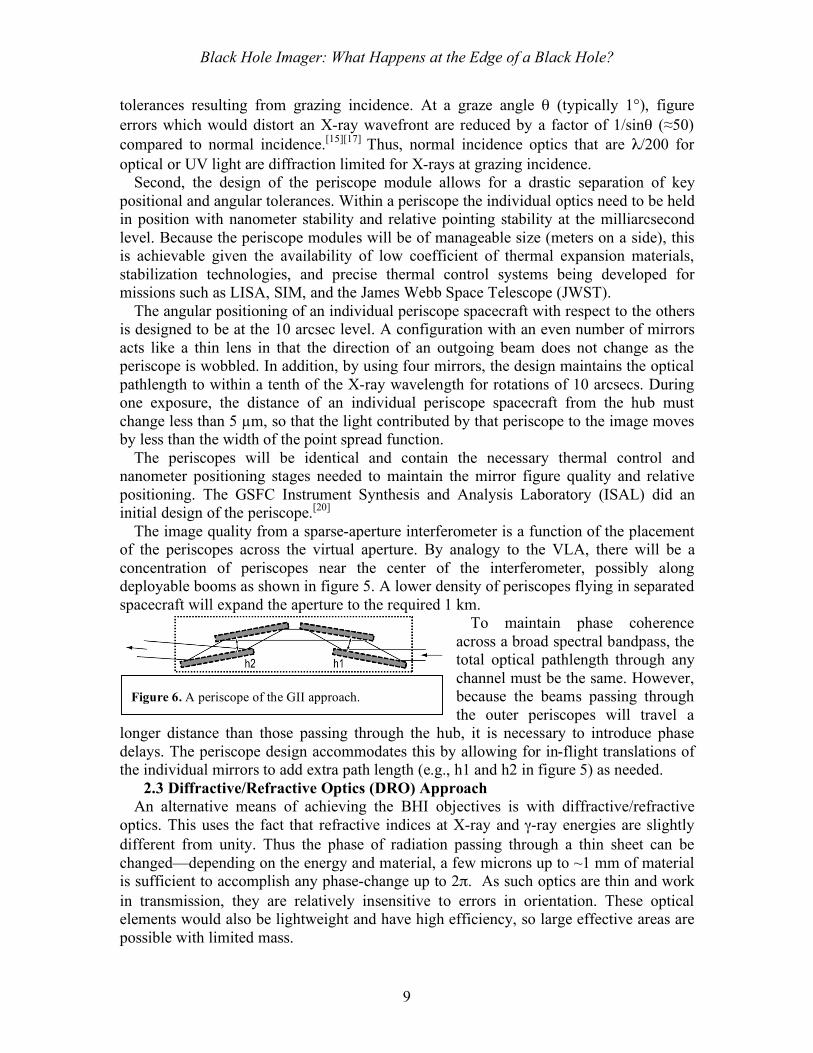
The angular positioning of an individual periscope spacecraft with respect to the others is designed to be at the 10 arcsec level. A configuration with an even number of mirrors acts like a thin lens in that the direction of an outgoing beam does not change as the periscope is wobbled. In addition, by using four mirrors, the design maintains the optical pathlength to within a tenth of the X-ray wavelength for rotations of 10 arcsecs. During one exposure, the distance of an individual periscope spacecraft from the hub must change less than 5 µm, so that the light contributed by that periscope to the image moves by less than the width of the point spread function.
The periscopes will be identical and contain the necessary thermal control and nanometer positioning stages needed to maintain the mirror figure quality and relative positioning. The GSFC Instrument Synthesis and Analysis Laboratory (ISAL) did an initial design of the periscope.[20]
The image quality from a sparse-aperture interferometer is a function of the placement of the periscopes across the virtual aperture. By analogy to the VLA, there will be a concentration of periscopes near the center of the interferometer, possibly along deployable booms as shown in figure 5. A lower density of periscopes flying in separated spacecraft will expand the aperture to the required 1 km.
To maintain phase coherence across a broad spectral bandpass, the total optical pathlength through any channel must be the same. However, because the beams passing through the outer periscopes will travel a
longer distance than those passing through the hub, it is necessary to introduce phase delays. The periscope design accommodates this by allowing for in-flight translations of the individual mirrors to add extra path length (e.g., h1 and h2 in figure 5) as needed.
2.3 Diffractive/Refractive Optics (DRO) Approach An alternative means of achieving the BHI objectives is with diffractive/refractive
optics. This uses the fact that refractive indices at X-ray and γ-ray energies are slightly different from unity. Thus the phase of radiation passing through a thin sheet can be changed—depending on the energy and material, a few microns up to ~1 mm of material is sufficient to accomplish any phase-change up to 2π. As such optics are thin and work in transmission, they are relatively insensitive to errors in orientation. These optical elements would also be lightweight and have high efficiency, so large effective areas are possible with limited mass.
Figure 6. A periscope of the GII approach.

Black Hole Imager: What Happens at the Edge of a Black Hole?
10
The most obvious form of such optics is a Phase Fresnel lens (PFL). This consists of a disk in which the thickness is varied radially so that incoming radiation reaches a focal point with the correct phase. A difficulty is that the focal length of such a lens varies in proportion to the photon energy. Recently, it has been realized that combining diffractive with refractive X-ray optics can produce configurations that are achromatic over a modest wavelength band[22-26]. A converging diffractive lens is combined with a weaker diverging refractive corrector. In practice, to minimize mass and absorption losses the refractive component would be stepped as indicated in Fig. 7B. Use of a low Z material such as beryllium minimizes the number of steps needed. Further improvement in the bandpass can be obtained by devoting subsections of the aperture to different energies.
At γ-ray energies sub-µas resolution can be obtained with a simple filled aperture lens 5–10 m in diameter. In the X-ray band, the system dimension has to be ~ 1 km, and so the “lens” becomes a dilute aperture system in which separate spacecraft carry optics that are each part of a complete lens of this size. Unlike GII periscopes, the diffractive optics cannot easily introduce the phase delays needed if the spacecraft are at different radii, so a circular configuration is preferred.
A dilute aperture Fresnel lens is essentially an interferometer similar to a GII except that the beams are diverted towards the common focal plane by elements that are essentially phase gratings, blazed to direct all the radiation into a single diffraction order. An interesting variation arises if the similarity is made even stronger by giving them a constant pitch, so that a parallel beam emerges. In this case it turns out that the fringes produced are achromatic (though fringes are produced only for a band of energies that depends on the size of the diffractors).
The performance of PFLs, particularly achromatic diffractive ones, is best when the focal length, f, is very long. For X-rays, a design with f ~ 20,000 km achieves this and also is compatible with a “plate-scale” such that 0.05 µas corresponds to a CCD pixel size of 5 µm. At higher energies the longer path length of generated electrons in detector materials will mean a larger pixel size and larger f.
As discussed in a technology white paper by Skinner et al., silicon PFLs working at up to 17 keV have been fabricated using grey-scale lithography and demonstrated in the laboratory. Although the lenses are small, the scale of the groove structure is such that it could be used for a flight lens, and the technology could be used for larger elements. Achromatic pairs and diffractive beam combiners have also been demonstrated (Fig. 7).
Figure 7. (Left) A: Cross-section through an X/γ-ray PFL. B: An achromatic diffractive/refractive combination. C: Same with the refractive component stepped. (Right) Projection of the image of a 5 µm slit in 8 keV X-rays with a 3-mm diameter PFL. Diffraction-limited response would correspond to 16.7 mas.

Black Hole Imager: What Happens at the Edge of a Black Hole?
11
2.4 Normal Incidence Interferometer (NII) Approach Another way to build an interferometer is to use diffraction-limited X-ray mirrors operating at normal incidence. It is feasible now because of the commercial availability of large-diameter diffraction-limited mirror substrates having 0.1–0.2 nm figure and finish specifications, developed over the past decade for the next-generation of sub-0.1-µm lithography tools. When coated with established ultra-short-period X-ray multilayers,[27]these substrates can be used to construct diffraction-limited X-ray mirrors operating over the energy range 0.35–0.83 keV. An interferometric array of such
mirrors, each operating in a prime-focus geometry, can be spread over a long baseline in order to achieve sub-µas angular resolution over a wide field of view.[10]
Normal-incidence multilayer mirrors have high efficiency only over a narrow spectral bandpass, of order Δλ=0.1 Å. In order to increase the overall spectral coverage of the instrument so as to make possible multi-wavelength image constructions (i.e., redshift maps), multiple, narrow-band interferometer channels would
be implemented, as illustrated conceptually in Fig. 8. That is, the system would comprise separate interferometer mirror arrays, with each mirror array coated with multilayers tuned to the desired wavelength. Thus to produce 3-color X-ray images, 3 separate interferometer channels would be used.
In order to maintain coherence in the NII approach, the positioning requirements on each mirror are stringent along the focal length (i.e., sub-nm), while control of the inter-mirror distances are relatively relaxed. Tight control of the mirror tilts about two axes are required as well.
Mirror fabrication and metrology available today can be used to produce diffraction-limited mirror segments 35 cm in diameter; these mirror segments can be rigidly co-aligned in order to construct even larger (~2 m) diffraction-limited mirrors. Stable ultra-short-period multilayers having peak reflectance ranging from ~0.6–6% have been demonstrated and significant performance gains over the coming years are expected. Nevertheless, even the current level of multilayer performance will be sufficient to produce interferometer channels having square-meters of effective area (Table 4).
Table 4. Angular resolutions and effective areas expected for an X-ray interferometer comprising an array of 32 normal-incidence multilayer mirrors, each 2 m in diameter, spread over a baseline B of 50 km, at the wavelengths indicated.
Ion Wavelength Peak Multilayer
Reflectance
Angular Resolution
Effective Area
! [Å] "#=!/B [µas] [m2]C VI 33.7 5.5% 0.014 5.5
N VII 24.8 1.8% 0.010 1.8
O VII 21.6 1.3% 0.009 1.3
O VIII 19.0 0.6% 0.008 0.6
Figure 8. A three-color normal incidence X-ray interferometer.
References can be found at the end of this document and at http://bhi.gsfc.nasa.gov/

Black Hole Imager: What Happens at the Edge of a Black Hole?
12
3. Technology Drivers 3.1 Formation Flying Common to all approaches to building a BHI is the need for multiple spacecraft flying
in formation. For BHI the basic formation flying (FF) situations are listed in Table 3. BHI is not alone in this requirement. The technology whitepaper by Carpenter et al. submitted to the ASTRO2010 committee outlines this general area, with particular emphasis on Stellar Imager, which has formation control requirements more challenging than the GII and DRO approaches, but slightly easier than the NII approach.
For all of the approaches, formation flying entails risk due to such issues as autonomous formation control, collision avoidance, spacecraft to spacecraft metrology, and other issues. There have only been limited autonomous formation flying demonstrations, the most recent of which involved the docking of ESA’s Jules Verne spacecraft with the International Space Station. The level of control for this demonstration was of order centimeters. Active FF with more than two spacecraft (which is needed for some BHI concepts) has yet to be demonstrated, though the Defense Advanced Research Projects Agency (DARPA) is in the midst of a development program called DARPA's Future, Fast, Flexible, Fractionated, Free-Flying System or “F6”[28] which may culminate in a demonstration within the next decade of multiple spacecraft formation flying. Precision spacecraft-to-spacecraft metrology at the level of microns has been demonstrated in NASA’s GRACE mission while LISA will push this to the picometer level.
For BHI, it is critical that progress be made in the following areas over the next decade:
1) Precision autonomous control at the level of microns (for GII and DRO) and Angstroms for NII. This requires inter-spacecraft metrology at the levels of 100 nm for GII and DRO (X-ray) and 100 pm for NII as well as control loops which accommodate otherwise minor disturbances such as solar radiation pressure and small gravity gradients. Thrusters ranging in force from µN to mN will also be required.
2) Methods to maintain formations which are “tight” (e.g., 25–30 spacecraft across an aperture 1 km in diameter) as well as long (e.g., 20,000 km between the optics and detectors). These should also address the need to repoint the array toward different targets on reasonable timescales which do not dominate the overall mission life, the simplicity of which is driven by the long distances between the detectors and optics.
3) Methods to validate formation flying of these large systems on the ground with combinations of testbeds and simulation.
A technology roadmap for formation flying is shown in section 5 while much more detail can be found in the Carpenter et al. technology white paper submitted to the ATRO2010 Decadal Review.
References can be found at the end of this document and at http://bhi.gsfc.nasa.gov/

Black Hole Imager: What Happens at the Edge of a Black Hole?
13
3.2 Line-Of-Sight Alignment Perhaps the most difficult issue for BHI is target acquisition and maintenance of the
tremendously tight line of sight (LOS) alignment (figure 9). Notice that this is different from pointing any individual spacecraft to the target. As discussed above, the various key optical components for the GII and DRO approaches act like thin lenses. They can change attitude (θo) by many arc seconds or degrees without image distortion. Similarly, the detector spacecraft can wobble without major consequence (θd). The difficult task is that we need to determine the relative alignment of the positions of all the components of BHI with respect to a line (green) between the detector and science target (dX). This is needed to the level of µas.
At the top level, there are two primary components to a LOS alignment system: a beacon system so that the position of one spacecraft can be measured relative to another, and some fixed reference to the target or the celestial sphere.
The beacon system, at least for initial acquisition, can consist of a laser on one spacecraft and an imager (e.g., star tracker) on the other. The laser is sized so that its output power and divergence are enough to deliver sufficient photons to the imager so that the imager can centroid the beacon to a fraction of our angular resolution goal for the overall BHI instrument. At visual wavelengths, this gets challenging quickly due to systematic effects in the optical design of the imager. To date, the “quartz telescope”[29]on GP-B is the best flown example of a system that can centroid on the optical light from a star to the 100 µas level. While this approach can be pushed in the optical, systematic effects may drive us to consider using the soft X-ray optics described for the NII approach as imagers of X-ray beacons. The diffraction limit of these X-ray optics minimizes the extreme centroiding requirements.
The target reference is another difficulty. Since we will probably not know absolute celestial coordinates of our BH targets to the µas level, we only need a relative reference that is stable for the duration of a typical BH observation (~106 seconds). One approach is to get this reference celestially—either, for example, by using a version of the Space Interferometry Mission (SIM) to look at stars or to use radio receivers distributed over the various spacecraft as a small radio interferometer aimed at quasars nearly orthogonal to our BHI target. Another approach is to get this reference inertially. High precision gyroscopes will need to be sensitive to rotations as the level of µas/second and stable for the observations. Possible gyroscopes which could be useful here include atomic interferometers[30-32], superfluid gyroscopes[33], or the kilometric optical gyroscope (KOG) considered at one time for the former Starlight mission.
A more detailed discussion of this situation for a 100 µas imager is discussed elsewhere[34]. Over the next decade this work will be extended to the sub-µas level. Technology developments for beacons and inertial references must continue.
Figure 9. LOS system in 1D.
References can be found at the end of this document and at http://bhi.gsfc.nasa.gov/

Black Hole Imager: What Happens at the Edge of a Black Hole?
14
3.3 Optics The three approaches to BHI discussed in section 2 use vastly different optics
technologies (e.g., Fig. 10) to achieve high angular resolution X-ray imaging. Each of these optical technologies has, to various extents, been demonstrated in the laboratory, but continued development is required to realize a BHI before 2030.
The GII approach has been validated analytically, with ray-tracing, and in the laboratory using small scale two-mirror-channel periscopes across ~1 mm baselines to produce fringes at 890 eV and 1.5 keV. While four-mirror periscopes have been modeled, they have not been tested in the laboratory. Flat mirrors of cm scales suitable for this work are readily available.
The DRO approach has been validated at ~8 keV and ~17 keV using gray-scale lithography produced PFLs with diameters of up to 5 mm. These experiments demonstrated nearly diffraction limited performance at GSFC’s 600 meter X-ray beamline. A diffractive interferometer has also been demonstrated at 8 keV A refractive/PFL optic has recently demonstrated achromatic imaging in the 8-11 keV range.
The optics of the NII approach have been demonstrated to have the correct figure, though they have only been used in the extreme ultraviolet (EUV) for cutting edge lithography work. The multilayer coatings which would make the EUV optics function in soft X-rays have been demonstrated. There is no reason to expect that these coatings will not work on the EUV optics.
In the coming decade, the following objectives are required to advance each approach:
GII Approach DRO Approach NII Approach • Demonstrate fringes with
larger baselines and larger optics
• Demonstrate four-mirror periscopes and path length control
• Demonstrate larger PFLs • Improve achromatic
performance • Further develop diffractive
interferometers
• Use Multilayer coatings on EUV optics and demonstrate X-ray performance
• Demonstrate an interferometer • Devise a pointing control system
Table 5. Objectives in Technology Development for BHI Optics in the 2011 Decade
Trade-off studies between the various options for the optics depend on the progress of technology development for each as well as their accommodations of BHI science drivers. The angular resolution that is really necessary must be traded against sensitivity and interferometry must be weighed against true imaging. Similarly the scientific advantages of different energy bands will influence the choice—NII is limited to very low energies and Fresnel lenses work better at high energies.
Figure 10. (Left) A 0.1–0.2 nm-figure normal-incidence optic. (Right) Scanning-electron micrograph of a 3-mm diameter PFL that demonstrated near diffraction-limited imaging at 8 keV. The inset shows a magnified portion of the innermost Fresnel profile[35].

Black Hole Imager: What Happens at the Edge of a Black Hole?
15
4. Activity Organization, Partnerships, and Current Status BHI concept development has been refined over the past decade by a team consisting
of scientists and engineers from several NASA centers, government agencies, universities, and industrial partners. Table 6 lists some historical team member institutions, many of which we anticipate will play a role in continued technology and concept development over the next decade. At the end of the last decade, there existed a science working group whose focus was black hole imager science. This group developed the initial requirements for a black hole imager and debated the different approaches to realize a BHI. During the current decade, there has been a very loose organization of the technology development with fleeting meetings of the original science working group. For instance, the GII approach is lead mostly by Dr. Webster Cash (University of Colorado, Boulder) and Dr. Keith Gendreau (NASA/GSFC) while the DRO technology development is lead by Dr. John Krizmanic (NASA/GSFC and USRA) and Dr. Gerry Skinner (NASA/GSFC and UMCP), and the NII approach is lead by Dr. David Windt (RXO). Formation flying efforts are very diverse with expertise located widely. Occasionally, some technology development is done under NASA’s Small Business Innovative Research (SBIR) program. On time scales of a few years, GSFC has lead overall mission formulation studies where science requirements are reviewed as well as the progress on the various component technologies. GSFC’s Integrated Mission Design Center (IMDC) and Instrument Synthesis Analysis Lab (ISAL) have been used to evaluate the concepts, estimate costs, and identify problem areas. The results are communicated to various technology development efforts for future iterations of the mission development.
For the coming decade, we propose to reconstitute a Science and Technology Working Group (STWG) to maintain the science requirements and mission concept development. The purpose of this organization is to better coordinate BHI specific efforts and keep up to date with other technology and mission development efforts which have overlap with BHI. Mission concept development will be lead by GSFC with inputs from the entire team.
Currently, our team has completed several IMDC/ISAL studies of BHI and BHI pathfinder concepts (see Table 8 in Costs). NASA’s ROSES program has funded efforts in GII and DRO technology development that have yielded exciting results including X-ray fringes from GIIs as well as nearly diffraction limited images from DROs using a 600 meter beamline at GSFC.
NASA/GSFC NASA/JPL NASA/MSFC NASA/GRC University of Colorado
MIT CalTech SAO USRA Stanford
Penn StateColumbia
University
University of
Maryland
Cambridge
University
Northrop Grumman Space
Technology
Ball
Aerospace
Lockheed
MartinNRL Aerojet RXO
Table 6. Institutions of team members historically involved with BHI concept development.

Black Hole Imager: What Happens at the Edge of a Black Hole?
16
5. Activity Schedule 5.1 Science and Technology Working Group
The STWG will have a mandate to coordinate science requirement updates, technology development, and overall mission concept development. It will work closely with NASA to help formulate NASA Research Announcments (NRA) geared toward a Black Hole Imager that can be realized by 2030. It will form at the onset of the coming decade with existing team members and a call to include others. 5.2 Technology Development Formation Flying
There are many overlaps in the required formation flying technology developments for BHI and other formation flying missions such as SI and New Worlds Observer (NWO). Key objectives for BHI formation flying technology are listed in section 3.1. Given the degree of overlap with other missions, we anticipate an R&D effort at the level of a few engineering FTEs per year each year with some funds for hardware. Line-of-Sight Alignment
The Line-of-Sight (LOS) system is perhaps the most challenging and most unique technology tall pole for BHI. As we discussed earlier, two key components of the solution are high precision beacons and a relative reference to the BHI science target. Section 3.2 lists some possible technologies for each of these components. Over the next decade, an effort of at least a few FTEs with funding for hardware is required to push these technologies forward. During overall mission concept studies (see section 5.3), we will conduct trade studies (e.g., figure 11) for the supporting technologies of this important system. Optics
We discussed the 3 active approaches to BHI above. Each had vastly different optics. During the past decade, NASA R&D funding significantly advanced these concepts, particularly DRO which was not considered for Black Hole Imaging at the time of the last NAS decadal review of astrophysics. This should continue for the three concepts we have spelled out. Key objectives of this development for the three BHI approaches are listed in section 3.3 and the technology white paper by Skinner et al. Developments in alternative approaches (e.g., Bragg optics) may also be attractive. For planning purposes, it will be necessary to fund continued R&D development of at least 4 different optics technologies for BHI during the coming decade at the level of 2 FTEs per effort per year. A Technology Roadmap for BHI
Table 7 shows a roadmap for our three most critical technologies. It indicates where we are now, what we need to work on in the coming decade, what other planned NASA missions will contribute to BHI’s advance through technological synergy, as well as BHI requirements.
Figure 11. LOS Technology Trade Study

Black Hole Imager: What Happens at the Edge of a Black Hole?
17
Table 7. A Technology Roadmap For Technology Tall Poles Where we are now Planned NASA missions
and BHI activities What BHI requires Fo
rmat
ion
Flyi
ng
• Passive Formation Flying: (e.g. EO-1, GRACE)
• Active Autonomous Formation Flying (Jules Verne/ISS)
• Interspacecraft Ranging at the µm level (GRACE)
• GSFC Formation Flying Testbed
• µN Thrusters TRL5 (LISA)
• Precision Intersatellite metrology: picometers (LISA, 2018?)
• Multispacecraft Formation Flying (MMS, DARPA’s F6)
• Autonomous control simulation and testbeds
• µN thrusters TRL9 (LISA)
• Interspacecraft metrology accurate to 0.01-100 nm
• Autonomous FF control of 2-30 S/C with precision of 0.1 nm- 10 micron
• µN thrusters with low-power and no contamination
• Low cost/power/mass S/C bus components
Line
-of-
Sigh
t A
lignm
ent
• Laboratory Demonstrations of Atomic Interferometer Gyroscopes and Super Fluid Gyroscopes
• Quartz Telescope of GP-B: 100 µas Centroiding
• 10% Efficiency Lasers (LISA)
• Continued development of atomic and Superfluid Gyroscopes with S/C packaging in mind.
• Demonstration of Diffraction Limited X-ray Beacon System
• Precision Line-of-Sight Alignment to< 0.1 µas
• Beacon system that provide < 0.1 µas relative position knowledge
• High resolution (sub µas /sec) rotation sensitivity with rate drift stability of pico-arcseconds/second
Opt
ics
• GII: Demonstration of Fringes with X-rays for ~mm baselines
• DRO: Demonstration of nearly diffraction limited image at 8 keV with a 5 mm diameter PFL+ achromatic corrector as well as a diffractive beam combiner
• NII: 35 cm diameter optics with 1 angstrom figure and multilayers with reflectivites ~<5.5%
• GII: Demonstrations of larger baselines with 4 mirror periscopes, phase closure and larger optics
• DRO: Increase PFL dimensions and improve achromatic performance
• NII: Demonstration of diffraction limited X-ray optics and interferometer
• GII: Light weight (< 10kg/m2) λopt/200 optics contained in ~1 m3 structures stable at the nm level; low-cost internal metrology to provide nm precision over cms-ms
• DRO: PFLs with dimensions of several meters on a side and > 10% bandpass
• NII: 2m normal incidence multilayer coated optics and a ~100 µas pointing control system
Bla
ck H
ole
Imag
er
5.3 Mission Concept Development It is invaluable to go through full mission planning exercises at various times using a
facility like NASA/GSFC’s Integrated Design Center or NASA/JPL’s “Team-X”. These efforts provide context to scientist and engineer alike.
The STWG will coordinate full mission concept studies in 2011, 2016, and 2020. 5.4 Pathfinder Feasibility
As many new missions are calling for formation flying technology, engineering demonstrations will prove necessary. It may be possible to use such opportunities to test BHI specific technologies. While engineering development will be the prime goal, such an opportunity could allow us to peer into the vast discovery space of milliarcsecond and better X-ray imaging (Section 1.3).
To realize such an opportunity, the BHI STWG will coordinate with other missions requiring formation flying. As the overlap in many technologies required for these missions is large, a joint pathfinder may yield a significant cost savings to NASA while propelling multiple compelling science objectives.

Black Hole Imager: What Happens at the Edge of a Black Hole?
18
6. Cost Estimates Here we will discuss our current best estimates of the costs for a Black Hole Imager as well as pathfinder missions which provide a more than three order of magnitude improvement in angular resolution compared to current X-ray observatories. Since we anticipate a full mission will not happen in the upcoming decade, we will also discuss the costs of development efforts that must occur in the upcoming decade in order to achieve full mission realization by 2030.
6.1 Current Estimates of Mission Costs Over the past few years we have utilized NASA/GSFC’s Integrated Mission Design Center (IMDC) and Instrument Synthesis and Analysis Laboratory (ISAL) to perform congruent multidiscipline engineering studies of BHI. These studies bring in discipline engineers from outside of our core team to perform intensive design studies. In addition to providing top level designs with information about orbits, mass to orbit, power requirements and other considerations discussed in our technical overview section, they also provide cost estimates based on parametric and grassroots models. We report these costing results in Table 8. The studies done to date are either for “pathfinder missions” which do not achieve the full science requirements spelled out in Section 1 or they are for supporting technologies. We can extrapolate from these studies to estimate the full implementation costs of a BHI which meets all science requirements spelled out to date to be in the $2-4B range. The IMDC and ISAL studies perfomed to date concentrated on the GII and DRO approaches we discussed earlier. The “Normal Incidence” approach was not studied, but
is very similar to “Stellar Imager” (SI) by Carpenter et al – though with formation flying requirements about 10 times stricter. The studies included “Pathfinder” missions which use the same technologies to achieve ~100 µas to 1 mas angular resolution and thus achieve a few components of our BHI science requirements, but, nonetheless, open up a significant amount of science discover space (figure 4). Mission cost estimates were derived in the IMDC using a commercially available
Department of Defense (DoD) developed parametric costing package called “Price-H”. Price-H provides system acquisition cost estimates based on quantitative, qualitative, and schedule parameters. Quantitative parameters include manufacturing quantities, mass, and volume of all the components required for the mission. Qualitative Parameters
Costing EffortYear of
Study
Assumed
Launch
Date
Mission
CostBasis Notes
MAXIM Pathfinder (II) IMDC Study
2002 2015$628.4
M
Price-H and
Grass Roots
2 operational Phases: 1 year with 100!as
Imaging and 3 years with 1 !as Imaging,
less area than desired for full mission.
Fresnel Lens Gamma-ray
Telescope IMDC Study
2002 2012$776.3
MPrice-H
Gamma-ray !as Imager in two
bandpasses, 3 year lifetime
Fresnel Lens Gamma-ray Telescope
Pathfinder IMDC Study
2002 2012 $457M Price-H
10 !as gamma ray imager in single bandpass, 3 year
lifetime
MAXIM Periscope Module ISAL Study
2003 2015$100M
for Optics
Price-H and
Grass Roots
Key optical component for
Grazing Incidence approach. Cost
savings from mass production
Table 8. Cost Studies Done for Some Limited Variations of BHI.

Black Hole Imager: What Happens at the Edge of a Black Hole?
19
include environmental specifications, equipment functions, and the complexity of technologies required. For full missions, costs from phase A through end of mission are included, but it is assumed that key science payloads are developed.
6.2Estimates of 2010 Decade Activity Costs During the last decadal survey, it was recommended that $60M be spent on technology development toward X-ray Interferometry for a future Black Hole Imager. While a fraction of this was disbursed, we made very good progress with several funded efforts. These funded efforts included laboratory demonstrations of X-ray interferometry using grazing incidence optics as well as limited mission concept formulation. In the past few years, results from diffractive optics approaches have yielded exciting results. For the coming decade, we anticipate continued progress in the development of technologies toward BHI. Table 9 lists expected activities with approximate annual funding levels as well as a basis for the estimate. These cost estimates where made in March 2009. These activities are primarily exclusive to BHI, but synergy with other missions (e.g., SI, NWO, and other formation flying missions) may yield some cost sharing.
Activity Duration
Total
Costs
[$M]
Basis
Refractive and Diffractive X-
ray and Gamma-Ray Lens
R&D
10 years 5
2 FTE's per year of Scientist
and Engineer Time Plus
Hardware
Grazing Incidence X-ray
Interferometry
Development
10 years 5
2 FTE's per year of Scientist
and Engineer Time Plus
Hardware
Normal Incidence X-ray
Interferometry
Development
10 years 5
2 FTE's per year of Scientist
and Engineer Time Plus
Hardware
Alternative Approaches to
Provide Contingency10 years 5
2 FTE's per year of Scientist
and Engineer Time Plus
Hardware
Formation Flying Technology
Development10 years 5
2 FTE's per year of Scientist
and Engineer Time Plus
Hardware
Line-of-Sight Alignment
Technology10 years 5
2 FTE's per year of Scientist
and Engineer Time Plus
Hardware
Mission Concept
Development
At
beginning,
Middle, and
End of
decade
1.5GSFC IDC and/or JPL Team-X
Costs Plus Team Involvement
Technology Pathfinder 5 50
Rough Estimate of
piggybacking BHI technology
on other FF mission for
evaluation
TOTAL 81.5
Table 9. Activities planned for the coming decade to ready technologies and mission concepts for realizing BHI before 2030. Cost estimates are indicative.

Black Hole Imager: What Happens at the Edge of a Black Hole?
20
References: [1]http://www8.nationalacademies.org/astro2010/DetailFileDisplay.aspx?id=106 [2]http://www8.nationalacademies.org/astro2010/DetailFileDisplay.aspx?id=222 [3]http://adsabs.harvard.edu/abs/2004MNRAS.355.1073I [4]http://www.iop.org/EJ/abstract/0004-637X/599/2/1238/ [5]http://adsabs.harvard.edu/abs/2008MNRAS.391...32D [6]http://adsabs.harvard.edu/cgi-bin/nph-abs_connect?library&libname=Black+Hole+Shadows&libid=49906960ed [7]http://adsabs.harvard.edu/abs/2006NewAR..50..796P [8]http://adsabs.harvard.edu/abs/1995PASP..107..803U [9]http://adsabs.harvard.edu/abs/1991ApJ...380L..51H [10]http://adsabs.harvard.edu/abs/1995ApJ...452..710N [11]http://www.nature.com/doifinder/10.1038/374623a0 [12] http://adsabs.harvard.edu/abs/1977MNRAS.179..433B [13] http://adsabs.harvard.edu/abs/2006ARA%26A..44..463H [14] http://adsabs.harvard.edu/abs/2007Sci...318..938T [15] http://adsabs.harvard.edu/abs/2000Natur.407..160C [16] http://adsabs.harvard.edu/abs/2004SPIE.5488..623A [17] http://adsabs.harvard.edu/abs/2000SPIE.4012..456S [18] http://adsabs.harvard.edu/abs/2001SPIE.4506..127C [19] http://adsabs.harvard.edu/abs/2003SPIE.4851..568S [20] http://adsabs.harvard.edu/abs/2004SPIE.5168..420G [21] http://adsabs.harvard.edu/abs/2004SPIE.5488..593L [22] http://adsabs.harvard.edu/abs/2001A%26A...375..691S [23] http://adsabs.harvard.edu/abs/2002A%26A...383..352S [24] http://adsabs.harvard.edu/abs/2007AdSpR..40.1276G [25] http://adsabs.harvard.edu/abs/2007ApOpt..46.2586B [26] http://adsabs.harvard.edu/abs/2004ApOpt..43.4845S [27] http://adsabs.harvard.edu/abs/2003SPIE.4851..441W [28] http://www.darpa.mil/tto/Programs/sf6.htm [29] http://einstein.stanford.edu/content/sci_papers/papers/WangS_2003_95.pdf [30] http://adsabs.harvard.edu/abs/2006PhRvL..97x0801D [31] http://adsabs.harvard.edu/abs/2007PhRvL..99q3201W [32] http://adsabs.harvard.edu/abs/1997PhRvL..78..760L [33] http://adsabs.harvard.edu/abs/1992PhRvB..46.3540P [34] http://adsabs.harvard.edu/abs/2003SPIE.4852..685G [35] http://www.ece.umd.edu/mems/projects/grayscale-pdf/JMEMS_Morgan_UMD_Feb2004.pdf