(bl25r series) - midway sales · part illustractions included branson front loader (bl25r series)...
TRANSCRIPT

Part Illustractions included
Branson Front Loader(BL25R Series)
Owner’s Manual
Branson Machinery LLC2100 Cedartown hwy Rome, GA, 30161Tel : 877-734-2022 Fax : 877-734-0637www.bransontractor.com
Part No. M15013Printed in Korea. June 2015
BL25R
Serie
sOWNER'S MANUAL
Branson Front Loader (BL25R Series)
Owner’s Manual
”Œ•£‰…˙¥` 1904.2.1 11:55 PM ˘ ` 1 ˆ •´¨fi ˛˙ˇ……¿ !!

- 1 -
CONGRATULATIONS! You have invested in the best implement of its type on the market today.
The care you give your Branson implement will greatly determine your satisfaction with its performance and its service life. We urge a careful study of
this manual to provide you with a thorough understanding of your new implement before operating, as well as suggestions for operation and
maintenance.
As an authorized Branson dealer, we stock genuine Branson parts which are manufactured with the same precision and skill as our original equipment.
Our trained service personnel are well informed on methods required to service Branson equipment, and are ready and able to help you.
Should you require additional information or assistance, please contact us.
YOUR AUTHORIZED BRANSON DEALER
Branson reserves the rights to change the specifications. The models and specifications
described here can be subjected to modifications for improvements without any prior notice
by the manufacturer.

- 2 -
Operator's Manual
TABLE OF CONTENTS
SECTION PAGE
Warranty ......................................................4 Dealer Preparation Check List ....................6 Safety Precautions.......................................7 Federal Laws & Regulations........................11
l. LOADER SPECIFICATIONS ........................13 II. INTRODUCTION & DESCRIPTION .............16
2-1 Introduction ...........................................16 2-2 Description ............................................15
lIl. PREPARATION FOR USE ...........................17 3-1 Attaching to Tractor ...............................17
lV. OPERATING INSTRUCTIONS ....................24 4-1 General Safety ......................................24 4-2 Operation ..............................................24 4-3 Transporting ..........................................39 4-4 Loader Detaching and Storage .............40
SECTION PAGE V. MAINTENANCE .........................................41
5-1 Maintenance Check list.........................41 5-2 Lubrication ............................................42 5-3 Hydraulic system Pressure Requirem-
ents............................................................44 5-4 Troubleshooting ....................... ...... ..............44
VI. INSTALL INSTRUCTION ..................................47 6-1 Assembly...............................................49 6-2 Safety Decals ........................................68 6-3 Torque Specifications .............................71
PARTS MANUAL ...............................................73 INDEX 1 ...................................................................100 INDEX 2 ...................................................................104 INDEX 3 ...................................................................109

- 3 -
RETAIL CUSTOMER'S RESPONSIBILITY
UNDER THE BRANSON WARRANTY
It is the Retail Customer and/or Operator's responsibility to read the Operator's Manual, to operate, lubricate,
maintain, and store the product in accordance with all instructions and safety procedures. Failure of the operator
to read the Operator's Manual is a misuse of this equipment.
It is the Retail Customer and/or Operator's responsibility to inspect the product and to have any part(s) repaired or
replaced when continued operation would cause damage or excessive wear to other parts or cause a
safety hazard.
It is the Retail Customer's responsibility to deliver the product to the authorized Branson dealer from whom he
purchased it, for service or replacement of defective parts which are covered by warranty. Repairs to be submitted
for warranty consideration must be made within forty-five (45) days of failure.
It is the Retail Customer's responsibility for any cost incurred by the Dealer for traveling to or hauling of the product
for the purpose of performing a warranty obligation or inspection.
UNDERSTAND SIGNAL WORDS
DANGER: Indicates an imminently WARNING: Indicates a potentially CAUTION: Indicates a potentially hazardous
hazardous situation which, if not avoided, hazardous situation which, if not situation which, if not avoided, will result in
death or serious injury. avoided, could result in death or may result in minor or moderate injury.
This signal word is to be limited to the serious injury. It may also be used to alert against
most extreme situations. unsafe practices

- 4 -
LIMITED WARRANTY
☆☆☆☆☆☆☆☆☆☆☆☆☆☆☆☆☆☆☆☆☆☆☆☆☆☆☆☆☆☆☆☆☆☆☆☆☆☆☆☆☆☆☆☆☆☆☆☆☆☆☆☆☆☆☆
Branson warrants to the original purchaser of any new Branson equipment, purchased from an authorized
Branson dealer, that the equipment be free from defects in material and workmanship for a period of one (1) year for
non-commercial, state, and municipalities' use and ninety (90) days for commercial use from date of retail sale. The
obligation of Branson to the purchaser under this warranty is limited to the repair or replacement of defective parts.
Replacement or repair parts installed in the equipment covered by this limited warranty are warranted for ninety
(90) days from the date of purchase of such part or to the expiration of the applicable new equipment warranty
period, whichever occurs later. Warranted parts shall be provided at no cost to the user at an authorized Branson
dealer during regular working hours. Branson reserves the right to inspect any equipment or parts which are claimed
to have been defective in material or workmanship.
DISCLAIMER OF IMPLIED WARRANTIES & CONSEQUENTIAL DAMAGES
Branson's obligation under this limited warranty, to the extent allowed by law, is in lieu of all warranties,implied
or expressed, INCLUDING IMPLIED WARRANTIES OF MERCHANTABILITY AND FITNESS FOR A PARTICULAR
PURPOSE and any liability for incidental and consequential damages with respect to the sale or use of the items
warranted. Such incidental and consequential damages shall include but not be limited to: transportation charges
other than normal freight charges; cost of installation other than cost approved by Branson; duty; taxes; charges
for normal service or adjustment; loss of crops or any other loss of income; rental of substitute equipment, expenses
due to loss, damage, detention or delay in the delivery of equipment or parts resulting from acts beyond the control
of Branson.

- 5 -
THIS LIMITED WARRANTY SHALL NOT APPLY:
1. To vendor items which carry their own warranties, such as engines, tires, and tubes.
2. If the unit has been subjected to misapplication, abuse, misuse, negligence, fire or other accident.
3. If parts not made or supplied by Branson have been used in connection with the unit, if, in the sole judgement of
Branson such use affects its performance, stability or reliability.
4. If the unit has been altered or repaired outside of an authorized Branson dealership in a manner which, in the
sole judgement of Branson, affects its performance, stability or reliability.
5. To normal maintenance service and normal replacement items such as gearbox lubricant, hydraulic fluid, worn
blades, or to normal deterioration of such things as belts and exterior finish due to use or exposure.
6. To expendable or wear items such as teeth, chains, sprockets, belts, springs and any other items that in the
company's sole judgement is a wear item.
NO EMPLOYEE OR REPRESENTATIVE OF BRANSON IS AUTHORIZED TO CHANGE THIS LIMITED WARRANTY IN
ANY WAY OR GRANT ANY OTHER WARRANTY UNLESS SUCH CHANGE IS MADE IN WRITING AND SIGNED BY
BRANSON'S SERVICE MANAGER, SEOUL, KOREA ☆☆☆☆☆☆☆☆☆☆☆☆☆☆☆☆☆☆☆☆☆☆☆☆☆☆☆☆☆☆☆☆☆☆☆☆☆☆☆☆☆☆☆☆☆☆☆☆☆☆☆☆☆
Record the model number, serial number and date
purchased. This information will be helpful to your MODEL NUMBER dealer if parts or service are required.
MAKE CERTAIN THE WARRANTY REGISTRATION SERIAL NUMBER CARD HAS BEEN FILED WITH BRANSON/
SEOUL, KOREA DATE OF RETAIL SALE

- 6 -
DEALER PREPARATION CHECK LIST
BEFORE DELIVERING MACHINE - The following check list should be completed.
Use the Operator's Manual as a guide.
■ Machine properly assembled.
■ All safety decals readable (See decal page).
■ All bolts tightened to torque specifications given in torque chart.
■ Machine operates properly.
■ Customer has appropriate mounting kit for his tractor and loader.
■ Operators manual has been delivered to owner and he has been instructed on the safe and proper use of
the front end loader.
CAUTION
It is recommended that the tractor be equipped with Rollover Protection System (ROPS) and
seat belt be used for all loader operations.
WARNING
To avoid serious injury or death, do not handle large heavy objects (large round bales,
machinery, etc.) with this loader.
It is the responsibility of the dealer to complete the procedures listed above before
delivery of this implement to the customer.
Dealer's Signature
THIS CHECKLIST TO REMAIN IN OWNER'S MANUAL
It is responsibility of the dealer to complete the procedures listed above before of this
implement to the customer

- 7 -
IMPORTANT SAFETY PRECAUTIONS
This symbol is used to call attention to safety
precautions that should be followed by
the operator to avoid accidents. When you
see this symbol, carefully read the message
that follows and heed its advice. Failure to
comply with safety precautions could result
in serious bodily injury.
In addition to the design and configuration of
equipment, hazard control and accident prevention are dependent upon the awareness, concern, prudence and
proper training of personnel in the operation, transport, maintenance and storage of equipment. Lack of attention to
safety can result in accident, personal injury, reduction of efficiency and worst of all-loss of life. Watch for safety
hazards and correct deficiencies promptly. Use the following safety precautions as a general guide to safe
operations when using this machine. Additional safety precautions are used throughout this manual for specific
operating and maintenance procedures. Read this manual and review the safety precautions often until you know
the limitations.
THE TRACTOR 1. Read the tractor operator's manual to learn how to operate your tractor safely. Failure to do so could result
in serious injury or death and equipment damage.
2. It is recommended that tractor be equipped with Rollover Protective System (ROPS) and a seat belt be used
for all loader operations.
3. When operating loader directly off tractor remotes always remove or lockout detent on tractor's hydraulic
valves.
This allows levers return to neutral position when released.
4. Add wheel ballast or rear weight for stability.
5. Move wheels to the tractor manufacturer's widest recommended settings to increase stability.
- 8 -
6. For better stability, use tractor with wide front axle rather than tricycle front wheels.
7. Move and turn the tractor at low speeds.
8. Stop tractor engine, place transmission in park (or neutral), engage parking brake, lower loader arms to
ground, cycle all hydraulic controls to relieve pressure, allow machine moving parts to stop, remove ignition
key to prevent unauthorized person from starting engine before dismounting tractor or serving, repairing, or
making adjustments to the equipment.
9. Wear personal protective equipment (PPE), such as, but not limited to, protection for eyes, ears, lungs, head,
hands and feet when operating, servicing, or repairing equipment. Avoid wearing loose clothing or jewelry
that may catch and entangle on equipment moving parts.
THE LOADER 1. Read the loader operator's manual to learn how to operate your loader safely. Failure to do so could result in
serious injury or death and equipment damage.
2. Become familiar with all the machine's controls and all the caution, warning and danger decals affixed to the
machine before attempting to start or operate.
3. Improper use of a loader can cause serious injury or death.
4. Do not lift or carry anybody on the loader or in the bucket or attachment.
5. Never allow anyone to get under the loader bucket or reach through the booms when the bucket is raised.
6. Do not walk or work under a raised loader bucket or attachment unless it is securely blocked or held in
position.
7. Avoid overhead wires and obstacles when loader is raised. Contacting electrical lines can cause
electrocution.
8. Make sure all parked loaders on stands are on a hard, level surface.
9. Use a piece of cardboard or wood rather than hands and wear eye protection when searching for hydraulic
leaks.
Escaping hydraulic oil under pressure can penetrate skin. If oil is injected into skin, it must be surgically
removed within a few hours by a doctor or gangrene may result.
10. Before disconnecting hydraulic lines, relieve all hydraulic pressure.
- 9 -
11. Do not tamper with the relief valve setting. The relief valve is preset at the factory. Changing the setting can
cause overloading the loader and tractor and serious operator injury may result.
12. Always wear safety goggles when repairing or servicing machine.
13. When servicing or replacing pins in cylinder ends, buckets, etc., always use a brass drift and hammer.
Failure to do so could result in injury from flying fragments.
14. Replace damaged or illegible safety decals. See decal page for required decals.
15. Do not modify or alter or permit anyone else to modify or alter the loader, any of its components or any
loader function without first consulting your local dealer.

- 10 -
OPERATING THE LOADER
1. It is the loader owner's responsibility to instruct and have a person read operator's manual, safety decals and
become familiar with machine controls before allowing them to operate loader.
2. Do not allow children to operate the loader.
3. Before starting or operating the equipment, make a walk around inspection and check for loose or damaged
components. Correct any deficiency before starting.
4. Keep the area of operation clear of all persons, particularly small children. The operator should cease
operation whenever anyone comes within the operating area.
5. Operate the loader from the "Operator's Seat Only."
6. Exercise caution when operating the loader with a raised loaded bucket or fork.
7. Avoid loose fill, rocks and holes. They can be dangerous for loader operation or movement.
8. Be extra careful when working on inclines.
9. Allow for the loader length when making turns.
10. Stop the loader arms gradually when lowering or lifting.
11. Use caution when handling loose or shiftable loads.
12. Carry loader arms at a low position during transport.
13. Lower loader arms, stop engine, and lock brakes before leaving the tractor seat.
14. Operate the loader controls only when properly seated at the controls.
15. Do not use loader for handling large, heavy objects such as logs, oil drums, etc.
16. Handling large, heavy objects is dangerous due to:
*Possibility of rolling the tractor over.
*Possibility of upending the tractor.
*Possibility of the object rolling or sliding down the loader arms onto the operator.
17. This is a Front End Loader. “Not a bulldozer”. Do not fit front blade attachment or
warranty for the tractor and front end loader will be void. !!!

- 11 -
IMPORTANT FEDERAL LAWS AND REGULATIONS* CONCERNING
EMPLOYERS, EMPLOYEES AND OPERATIONS.
*(This section is intended to explain in broad terms the concept and effect of the following federal laws and
regulations.
It is not intended as a legal interpretation of the laws and should not be considered as such).
U.S. Public Law 91-596 (The Williams-Steiger Occupational and Health Act of 1970) OSHA
This Act Seeks: "...to assure so far as possible every working man and woman in the nation safe and healthful working conditions
and to preserve our human resources..."
DUTIES Sec. 5 (a) Each employer-
(1) shall furnish to each of his employees employment and a place of employment which are free from
recognized hazards that are causing or are likely to cause death or serious physical harm to his employees;
(2) shall comply with occupational safety and health standards promulgated under this Act.
(b) Each employee shall comply with occupational safety and health standards and all rules, regulations and
orders issued pursuant to this Act which are applicable to his own actions and conduct.
OSHA Regulations Current OSHA regulations state in part: "At the time of initial assignment and at least annually thereafter, the
employer shall instruct every employee in the safe operation and servicing of all equipment with which the
employee is, or will be involved." These will include (but are not limited to) instructions to:
Keep all guards in place when the machine is in operation;

- 12 -
Permit no riders on equipment;
Stop engine, disconnect the power source, and wait for all machine movement to stop before servicing,
adjusting, cleaning or unclogging the equipment, except where the machine must be running to be properly
serviced or maintained, in which case the employer shall instruct employees as to all steps and procedures
which are necessary to safely service or maintain the equipment.
Make sure everyone is clear of machinery before starting the engine, engaging power, or operating the
machine.
EMPLOYEE TRACTOR OPERATING INSTRUCTIONS:
1. Securely fasten your seat belt if the tractor has a ROPS.
2. Where possible, avoid operating the tractor near ditches, embankments, and holes.
3. Reduce speed when turning, crossing slopes, and on rough, slick, or muddy surfaces.
4. Stay off slopes too steep for safe operation.
5. Watch where you are going, especially at row ends, on roads, and around trees.
6. Do not permit others to ride.
7. Operate the tractor smoothly - no jerky turns, starts, or stops.
8. Hitch only to the drawbar and hitch points recommended by tractor manufacturers.
9. When tractor is stopped, set brakes securely and use park lock if available
Child Labor Under 16 Years Old
Some regulations specify that no one under the age of 16 may operate power machinery. It is your responsibility to
know what these regulations are in your own area or situation. (Refer to U.S. Dept. of Labor, Employment Standard
Administration, Wage & Home Division, and Child Labor Bulletin #102.)

- 13 -
SECTION I
LOADER SPECIFICATIONS
Loader model BL25R / BL25R1 Remark
Tractor model Branson 3220R/3520R/3520H/4020R/4720H/5220R
Front tire 8 – 18(Ag)
Rear tire 12.4 – 24(Ag)

- 14 -
A Maximum Lift Height to pivot pin 103.8 in. 2636 mm
B Clearance with Attachment Level 97.3 in. 2471 mm
C Clearance with Attachment Dumped 78.9 in. 2004 mm
D Reach at Maximum Height 25.6 in. 650 mm
E Maximum Dump Angle 44 degree ←
F Reach with Attachment on Ground 67.3 in. 1709 mm
G Maximum Rollback Angle 24.5 degree ←
H Digging Depth Below Grade 1.96 in. 50 mm
J Overall Height in Carry Position 47.6 in. 1209 mm
L Depth of Attachment (to back of inner shell) 23.7 in. 601 mm
M Height of Attachment 22.0 in. 461 mm
N Depth of Attachment (to pivot pin) 29.0 in. 736 mm
Lift Capacity to Full Height @ Pivot Pins 2089 lbs
Breakout Force @ Ground Level, pivot pin 3531 lbs
Relief Valve Setting (Loader Control Valve) 2489 psi
Rated Flow(Tractor System) 8.24 GPM
Bucket Size 68.5 in.
Weight(With Bucket) 1160 lbs
Cycle Times 2,600 rpm(Full)
Raise Boom Frame 4.4
Lower Boom Frame 3.1
Dump Bucket 2.9
Retract Bucket 2.2

- 15 -
SECTION II
INTRODUCTION AND DESCRIPTION
2-1 INTRODUCTION We are pleased to have you as a Branson customer. Your Front end Loader has been carefully designed to give
maximum service with minimum down time. This manual is provided to give you the necessary operating and
maintenance instructions for keeping your loader in top operating condition. Please read this manual thoroughly.
Understand what each control is for and how to use it. Observe all safety precautions decaled on the machine and
noted throughout the manual for safe operation of implement. If any assistance or additional information is needed,
contact your authorized Branson dealer.
2-2 DESCRIPTION The Front End Loader is designed for four-wheel drive tractors. They are intended to lift only loose materials that will
fit in the bucket. All cylinders are double-acting. Parking stands support loader so tractor can be "driven in" for
quick attaching. Major components of loader are shown in Figure 2-1.

- 16 -
Figure 2-1 Major Component
Sub Frame
Bumper
Back Axle
Bucket Cylinder
Boom Cylinder
Bucket
Boom

- 17 -
SECTION lIl PREPARATION FOR USE
3-1 ATTACHING TO TRACTOR
WARNING WEIGHT SHOULD BE APPLIED TO TRACTOR REAR WHEELS AND/OR 3-POINT HITCH TO INCREASE STABILITY.
WARNING TO AVOID INJURY OR DEATH:
ALWAYS CONNECT LOADER HOSES TO APPROPRIATE TRACTOR AUXILIARY OUTLET. ALWAYS REMOVE OR LOCKOUT TRACTOR'S
HYDRAULIC VALVES DETENT POSITIONS FOR LEVER NEUTRAL RETURN WHEN RELEASED.
It is recommended that tractor wheels be moved to the widest setting and rear ballast be applied to increase tractor
stability. Three point hitch mounted weights are available from your Branson dealer. Air pressure in front tires should
be adequate for heavy loads. Refer to tractor owner's manual for further instructions. Attach loader
to tractor as follows:

- 18 -

- 19 -

- 20 -

- 21 -

- 22 -

- 23 -
- 24 -
SECTION lV
OPERATING INSTRUCTIONS
CAUTION
DO NOT LIFT ROUND HAY BALES. ROUND BALES CAN ROLL DOWN LOADER ARMS CAUSING SERIOUS INJURY
OR DEATH TO OPERATOR.
4-1 GENERAL SAFETY Only qualified people familiar with this manual should operate this machine. Operator should wear hard hat, safety
glasses and safety shoes. The operator should read, understand and practice all safety messages shown on the
caution, warning and danger decals affixed to the loader to avoid serious injury or death. It is recommended that
tractor be equipped with Rollover Protective System (ROPS) and a seat belt be used. Check for ditches, stumps, holes
or other obstacles that could upset tractor or damage loader. Fluid and/or weights for rear tires is recommended for
added stability. See tractor operator's manual. Three point hitch mounted weights are available from your Branson
dealer. Always turn off tractor engine, set parking brake and lower loader to ground before dismounting tractor. See
page 4 for additional safety precautions.
4-2 OPERATION The loader should be operated with the tractor engine running at 1200-1700 rpm. Excessive speeds are dangerous
and may cause bucket spillage and unnecessary strain on both the tractor and loader.
The following text and illustrations offer suggested loader and tractor operating techniques.

- 25 -
FILLING THE BUCKET Approach and enter the pile with a level bucket. Ease lever back and toward you to lift and rollback the bucket.
The lift and rollback of the bucket will increase efficiency because a level bucket throughout the lifting cycle resists
bucket lift and increases breakaway effort.
NOTE: Do not be concerned if the bucket is not completely filled during each pass. Maximum
productivity is determined by the amount of material loaded in a given period of time. Time is
lost if two or more attempts are made to fill the bucket on each pass

- 26 -
LIFTING THE LOAD
WARNING DO NOT LIFT OR CARRY ANYONE IN THE BUCKET OR ON ANY OTHER POSITION OF THE LOADER OR LOADER ATTACHMENT. INADVERTENT
MOVEMENT OF THE LOADER OR ATTACHMENT COULD RESULT IN SERIOUS INJURY OR DEATH FROM FALLING OR CRUSHING.
CAUTION MAKE SURE MATERIAL IN BUCKET CANNOT ROLL OUT AND DOWN ON TRACTOR WHEN BUCKET IS RAISED TO FULL HEIGHT. KEEP CLEAR
OF OVERHEAD OBSTRUCTIONS SUCH AS TREES, LIMBS OR POWER LINES WHEN RAISING THE BUCKET.
When lifting the load, keep the bucket positioned to avoid spillage.

- 27 -
CARRYING THE LOAD Position the bucket just below the level of the tractor hood for maximum stability and visibility, whether the bucket is
loaded or empty.
Use extreme caution when operating the loader on a slope, keep the bucket as low as possible, this keeps the bucket
and tractor center of gravity low and will provide maximum tractor stability.
CAUTION OPERATING THE LOADER ON A HILLSIDE IS DANGEROUS. EXTREME CARE IS RECOMMENDED.
- 28 -
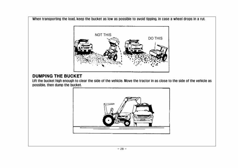
When transporting the load, keep the bucket as low as possible to avoid tipping, in case a wheel drops in a rut.
DUMPING THE BUCKET Lift the bucket high enough to clear the side of the vehicle. Move the tractor in as close to the side of the vehicle as
possible, then dump the bucket.

- 29 -
LOWERING THE BUCKET After the bucket is dumped, back away from the vehicle while lowering and rolling back the bucket.
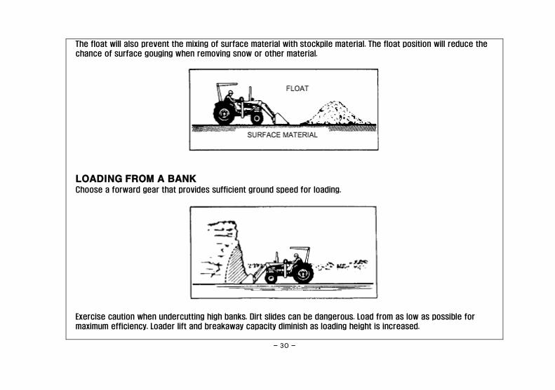
OPERATING WITH FLOAT CONTROL During hard surface operation, keep the bucket level and put the lift control in the float position to permit the bucket
to float on the working surface. If hydraulic down pressure is exerted on the bucket, it will wear faster
than normal.
- 30 -
The float will also prevent the mixing of surface material with stockpile material. The float position will reduce the
chance of surface gouging when removing snow or other material.
LOADING FROM A BANK Choose a forward gear that provides sufficient ground speed for loading.
Exercise caution when undercutting high banks. Dirt slides can be dangerous. Load from as low as possible for
maximum efficiency. Loader lift and breakaway capacity diminish as loading height is increased.

- 31 -
Side cutting is a good technique for cutting down a big pile.
If the pile sides are too high and liable to cause cave-in, use the loader to break down the sides until a slot can be
cut over the top.

- 32 -
Another method for large dirt piles is to build a ramp approach to the pile.
It is important to keep the bucket level when approaching a bank or pile. This will help prevent gouging the work area.

- 33 -
PEELING AND SCRAPING
Use a slight bucket angle, travel forward, and hold the lift control forward to start the cut. Make a short, angle cut
approximately 6" deep and break out cleanly.
With the bucket level, start a cut at the notch approximately 2" deep. Hold the depth by feathering the bucket control
to adjust the cutting lip up or down. When the front tiress enter the notch, adjust the lift cylinder to maintain proper
depth.

- 34 -
Make additional passes until the desired depth is reached. During each pass, only use the bucket control while at
working depth. This will allow you to concentrate on controlling the bucket angle to maintain a precise cut.
LOADING LOW TRUCKS OR SPREADERS FROM A PILE
For faster loading, minimize the angle of turn and length of run between pile and spreader.
- 35 -
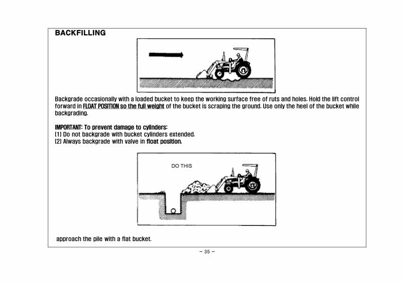
BACKFILLING
Backgrade occasionally with a loaded bucket to keep the working surface free of ruts and holes. Hold the lift control
forward in FLOAT POSITION so the full weight of the bucket is scraping the ground. Use only the heel of the bucket while
backgrading.
IMPORTANT: To prevent damage to cylinders:
(1) Do not backgrade with bucket cylinders extended.
(2) Always backgrade with valve in float position.
approach the pile with a flat bucket.

- 36 -
Poor methods actually move no more dirt and make it more difficult to hold a level grade.
Do not use the bucket in the dumped position for bulldozing or backgrading. This method, shown above, will impose
severe shock loadings on the dump linkage, the bucket cylinder, and the tractor.
Leave dirt in the bucket because dumping on each pass wastes time.

- 37 -
Operate at right angles to the ditch. Take as big a bite as the tractor can handle without lugging down.
Leave dirt which drifts over the side of the bucket for final clean-up.

- 38 -
Pile dirt on the high side for easier backfilling on a slope.
HANDLING LARGE HEAVY OBJECTS
WARNING Do not use front end loaders for handling large, heavy objects such as large, round or rectangular bales, logs and oil
drums.
Handling large heavy objects can be extremely dangerous due to:
ㆍ Possibility of rolling the tractor over.
ㆍ Possibility of upending the tractor.
ㆍ Possibility of the object rolling or sliding down the loader arms onto the operator.

- 39 -
4-3 TRANSPORTING When transporting on road or highway, day or night, use tractor flashing warning lights unless prohibited by law. Carry
load as low as possible maintaining adequate ground clearance and visibility. Reduce tractor ground speed when
transporting a load. Take extra care when traveling over rough terrain or on slopes.
CAUTION WHEN TRANSPORTING THE LOAD, KEEP THE BUCKET AS LOW AS POSSIBLE TO RESIST TIPPING, IN CASE A WHEEL DROPS IN A RUT.
THIS WILL AVOID TIPPING AND POSSIBLE INJURY.

- 40 -
4-4 LOADER DETACHING AND STORAGE
NOTE When loader hydraulics are disconnected from tractor the tractor hydraulic circuit must be completed. Failure to do
so will result in tractor hydraulic pump damage.
A. Remove parking stands from storage. Raise boom and install as shown in Figure 3-1.
WARNING NEVER STAND UNDER LOADER WHILE INSTALLING/REMOVING PARKING STANDS.
B. Lower boom until parking stands contact ground.
C. Extend bucket cylinders (dump) until cutting edge of bucket is firmly on the ground.
D. Remove pin from front mounting bracket.
E. Remove nuts and clamps securing loader sub-frame to rear mounting bracket.
F. With tractor at IDLE SPEED carefully roll bucket back until sub-frame raises off rear bracket.
G. Carefully activate boom cylinders until cross tube is free of pressure within front bracket channel.
H. Disconnect hydraulic hoses.
I. Carefully back tractor out of loader.
J. Pin clamps back to sub-frame and place pin back in front mounting bracket for storage.
K. Clean dirt and debris from loader. Dirt will hold moisture and cause rust.
L. If loader is to be stored for an extended period of time, perform lubrication per paragraph 4-2 Also apply a coat
of heavy grease to exposed cylinder rods to prevent rusting.

- 41 -
SECTION V
MAINTENANCE
5-1 MAINTENANCE CHECK LIST Perform scheduled maintenance as outlined below. Lower machine to ground, turn off tractor and set parking brake
before doing maintenance inspections or work. All bolts should be torqued as recommended in torque chart on inside
of back cover unless otherwise indicated.
CAUTION
USE A PIECE OF CARDBOARD OR WOOD RATHER THAN HANDS AND WEAR EYE PROTECTION WHEN SEARCHING FOR HYDRAULIC LEAKS.
ESCAPING HYDRAULIC OIL UNDER PRESSURE CAN PENETRATE SKIN. IF OIL IS INJECTED INTO SKIN, IT MUST BE SURGICALLY REMOVED
WITHIN A FEW HOURS BY A DOCTOR OR GANGRENE MAY RESULT.
WARNING THE LOADER CAN FALL FROM HYDRAULIC SYSTEM FAILURE. TO AVOID SERIOUS INJURY OR DEATH, SECURELY SUPPORT LOADER
BEFORE WORKING UNDERNEATH.

- 42 -
BEFORE EACH USE 1. Inspect hydraulic lines and fittings for wear or leaks. Repair or replace if needed.
2. Inspect all pivot pins for wear. Make certain cotter pins are installed to retain each pivot pin.
3. Check all bolts for tightness.
4. Perform BEFORE EACH USE lubrication per paragraph 5-2.
5. During operation, listen for abnormal sounds which might indicate loose parts or other damage.
AFTER EACH USE 1. Clean all debris from machine.
5-2 LUBRICATION (Figure 5-1)
NOTE
The multipurpose grease referenced in this section is an NLGI Grade 2 type grease.
BEFORE EACH USE 1. Boom Pivot Pins- Apply multi-purpose grease to each fitting (1 fitting each side)
2. Boom Cylinders- Apply multi-purpose grease to each fitting (2 fittings each cylinder)
3. Bucket Cylinders- Apply multi-purpose grease to each fitting (2 fittings each cylinder)
4. Bucket Pivot Pin- Apply multi-purpose grease to each fitting (1 fitting each side)
5. Link Pivot Pin-Apply multi-purpose grease to each fitting (2 or 3 fitting each side)
6. Tractor Hydraulic Oil- Cycle boom and bucket cylinders 2 or 3 times before use then check tractor hydraulic oil
level per tractor operator's manual.

- 43 -
Figure 5-1 Lubrication Points

- 44 -
5-3 HYDRAULIC SYSTEM PRESSURE REQUIREMENTS
A tractor hydraulic system pressure setting of 2400 psi is recommended for maximum efficiency and service. The
Branson control valve is pre-set at factory and should not be adjusted
5-4 TROUBLESHOOTING
Troubleshooting procedures are listed in table 5-1. If the problem cannot be solved or replacement parts are
necessary, contact your authorized Branson dealer. Please have ready your machine name, model number, serial
number, purchase date, and exact cause or description of problem.
TABLE 5-1
PROBLEM POSSIBLE CAUSE REMEDY
1. Loader slow and/or will not
dump.
Hydraulic oil too heavy.
Oil filter plugged.
Hydraulic pump worn.
Oil line restricted or leaking.
Quick couplers not properly
connected.
Control valve does not shift
properly.
Air in hydraulic system.
Cylinder leaks internally.
Faulty valve.
Change to proper oil.
Clean or replace filter.
Repair or replace pump.
Check all hoses and tubes for leaks,
damage or restrictions.
Replace damaged or restricted
hoses or tube lines.
Check connection - Replace if
necessary.
Inspect, clean, repair or replace
valve.
Cycle lift cylinders and bucket
cylinders several times to free
system of air.
Replace seals.
Replace or repair valve.

- 45 -
PROBLEM POSSIBLE CAUSE REMEDY
2. Loader chatters or vibrates
when raising or lowering.
Air leak in pump inlet line.
Air in hydraulic system.
Oil level too low.
Check, tighten or replace inlet. line.
Cycle lift and bucket cylinders.
Add oil as required.
3. Pump noisy.
Inlet line restricted or leaking.
Oil level too low.
Pump worn or damaged.
Check for air leaks restrictions or
collapsed hose. Tighten or replace
hose. Clean filter if necessary.
Add oil as required.
Repair or replace pump.
4. Oil leaks.
Defective fittings or hoses.
Loose Connections.
Worn or damaged O-ring or wiper
seal in cylinder rod end.
Worn or damaged O-rings in valve.
Replace defective parts.
Tighten fittings.
Install a seal repair kit.
Install an O-ring repair kit.

- 46 -
PROBLEM POSSIBLE CAUSE REMEDY
5. Insufficient lift capacity.
Improper hydraulic pump
operation.
Load is greater than boom lift
capacity.
Internal boom cylinder leakage.
Improper hydraulic valve
operation.
Repair or replace pump.
Check loader specifications.
Replace any worn parts and
install a seal repair kit.
Repair or replace valve.
6. Excessive wear on bucket
Bucket is riding on cutting edge
instead of wear pads.
Use boom "FLOAT" position or
bucket level indicator to ensure
bucket rides on wear pads.
7. Slow leakdown. Worn control valve.
Worn cylinder piston seals.
Have authorized Branson dealer
replace seals.
8. Hydraulic cylinders inoperative. Hose from control valve
improperly connected.
Refer to plumbing diagrams in
Section V.
9. Loader lift and bucket tilt
controls do
Hoses improperly connected. Refer to plumbing diagrams in
Section V and correct hose
connections.

- 47 -
SECTION VI
INSTALL INSTRUCTION
CAUTION
THE FOLLOWING SAFETY PRECAUTIONS SHOULD BE THOROUGHLY UNDERSTOOD BEFORE ATTEMPTING MACHINE ASSEMBLY.
1. Do not lift heavy parts or assemblies. Use crane, jack, tackle, fork trucks, or other mechanical devices.
2. Select an area for assembly that is clean and free of any debris which might cause persons working on the
assembly to trip.
3. Arrange parts to be assembled neatly in the work area and have tools and other mechanical assisting devices in
easy reach.
4. Inspect all parts and assemblies thoroughly and remove any sharp edges, grease, oil, or dirt which might cause
pieces to slip when handling.
5. Preview the assembly instructions in your operator's manual before proceeding further.
6. If the assembly instructions call for parts or assemblies to be blocked up, use only blocking material that is in
good condition and is capable of handling the weight of the assembly to be blocked. Also, insure that the
blocking material is on a clean, dry surface.
7. Never put hands or any other body under blocked up assemblies if at all possible.
8. Always wear goggles or safety glasses when hammering, grinding or drilling metal parts.
9. If the assembly calls for welding or cutting, be sure that there are no flammable materials close at hand and
that bystanders have taken necessary precautions.
AFTER COMPLETING ANY ASSEMBLY STEP, THOROUGHLY READ THE NEXT STEP IN THE ASSEMBLY INSTRUCTIONS BEFORE PROCEEDING
WITH THAT STEP.
10. After completing assembly, thoroughly inspect the machine to be sure that all nuts, bolts, hydraulic fittings or
any other fastened assemblies have been thoroughly tightened.
11. After completing assembly be sure that all safety locking devices or guards are in place.
12. Before operating the machine, thoroughly read the operation section of this manual.

- 48 -
13. Before operating, read the maintenance section of this manual to be sure that any parts requiring lubrication
such as gearboxes are full to avoid any possible damage.
14. Wear personal protective equipment such as, but not limited to, protection for eyes, ears, feet, hands, lungs
and head when assembling the equipment. Do not wear loose clothing or jewelry that may catch on equipment
moving parts.
BEFORE OPERATING THE EQUIPMENT, IF YOU HAVE ANY QUESTIONS REGARDING THE PROPER ASSEMBLY OR OPERATION, CONTACT YOUR
AUTHORIZED BRANSON DEALER OR REPRESENTATIVE.

- 49 -
6-1 ASSEMBLY INSTALL PRECAUTION!
Please read the Tractor operator's manual for Safety and Operation before installing the Loader.
1. BOOM
2. BUCKET
3. SUB-FRAME RH
4. SUB-FRAME LH
5. UNDERBAR & SMALL PARTS
6. BACKAXLE RH
7. BACKAXLE LH
8. BUMPER
- 50 -
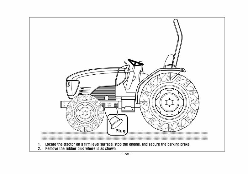
1. Locate the tractor on a firm level surface, stop the engine, and secure the parking brake.
2. Remove the rubber plug where is as shown.
- 51 -
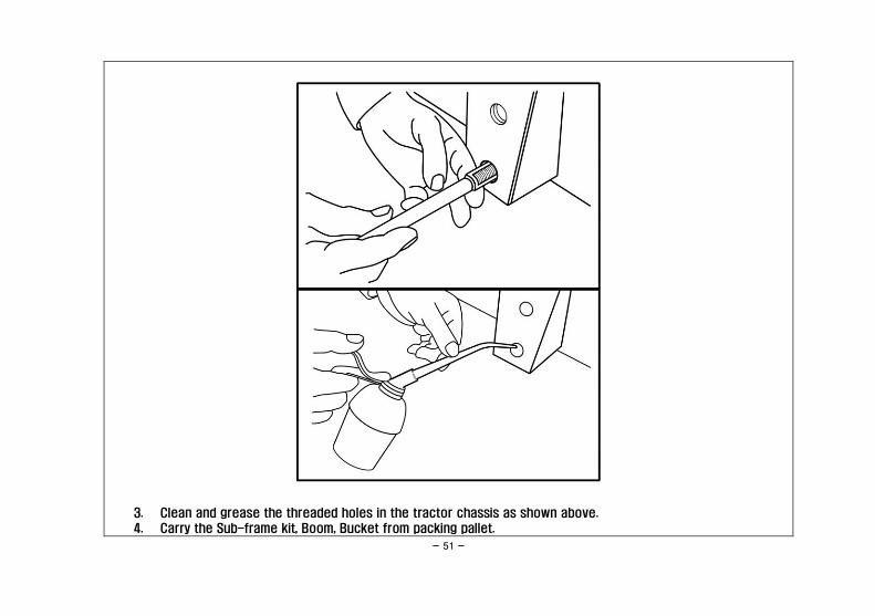
3. Clean and grease the threaded holes in the tractor chassis as shown above.
4. Carry the Sub-frame kit, Boom, Bucket from packing pallet.

- 52 -
5. Install the Left, and Right Sub-Frame as above shown.
①. -. 4-M16x45L BOLT
-. 4-M16 SPRING WASHER
②. -. 2-M12x125L BOLT
-. 2-M12 SPRING WASHER
-. 2-Ø27x Ø19.4x69L SPACER
③. -. 2-M14x50L BOLT
-. 2-M14 SPRING WASHER
Important – Do not tighten any bolts firmly until most components are attached to the tractor.

- 53 -
6. Install the Left, and Right Back Axle as above shown.
①. By using Bolt for fixing Rops Frame which is offered from Tractor itself install as above shown.
②. -. 2-M20x70L BOLT
-. 2-M20 SPRING WASHER
-. 1-M20 NUT
③. Install the Cross Bar(C30-09-6100) following picture's Sub-Frame inside.
Important - All Bolts should be assembled with using adequate Torque in compliance with the Torque Specification Chart
" Page 71 ".

- 54 -
7. As above shown, Assemble the Bumper to the Front axle frame.
-. 4-M16x80L BOLT
-. 4-M16 SPRING WASHER
-. 4-M16 NUT
Important - Referring to picture. Ensure that the mounting direction of the bumper.
- 55 -
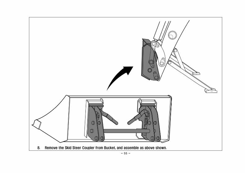
8. Remove the Skid Steer Coupler from Bucket, and assemble as above shown.

- 56 -
9. As shown above, hang up at the center of gravity of Boom ass’y and move.

- 57 -
①. Assemble the loader to Sub-Frame.

- 58 -
②. Install the Pin (P25-1030)
③. As above shown, secure Link Pin (AL20-98-9990) which is located inside.

- 59 -
10. Assemble the Indicator as above shown.
①. 1-INDICATOR 2540A-450A
②. 1-SPLIT PIN (Ø3) PD03025

- 60 -
11. Connect four hydraulic hoses, with quick couplers, between the hydraulic tube lines and the control valve as
indicated with color marks. Then connect the protective caps and plugs to each other.
Important - Check again the bolt's fastening torque, and each Pin has enough grease inside.
※ Refer page 64 for BL25R1

- 61 -
12. After a few minutes warming up the engine by turning on the tractor,
①. Operate the boom to Rise and Down 6 times,
②. Operate full stroke dump and crowd 6 times at 1.2m from ground,
③. Check the tractor transmission fluid level, add it necessary.
Refer to the tractor operator’s manual for instructions and proper fluid.
Repeat this check after purging air from the system. At that time, it will be necessary to add transmission
fluid.
Important1 – To check the transmission fluid level, lower the loader to the ground and lower the 3 point hitch.
Important2 - While using the loader, when the leakage of hydraulic oil or hydraulic circuit components replace, should
check the amount of oil

- 62 -
13. Put the bucket position to front of tractor.
Engage the bucket to Skid Steer Coupler by drive forward the tractor
Important - Remove the vicinity objects around the tractor, far from the tractor except for operator as well.

- 63 -
14. When the Bucket is properly seated in the saddle and against the front of the skid steer coupler plate, turn off
the engine and set the parking brake. Push the skid steer coupler handles to the fully latched position.
Verify both latching pins are completely engaged in the base of the Bucket.

- 64 -
※Assembly for BL25R1 Hydraulic parts
1. Attach the Control Valve Bracket in the RH
Sub Frame.
-. 1-K2840B-1800 Control Valve Bracket
-. 2-M10x40L Bolt
-. 2-M10 Spring Washer
-. 2-M10 Nut
2. Assemble the Control Valve on the Control
Valve Bracket
3-M8x70L Bolt
3-M8 Spring Washer
3-M8 Nut

- 65 -
3. Remove the plastic plug from each port of
control valve.
4. Assemble the fittings at the A1, B1, A2, B2 port
of control valve as shown.
-. 4-Quick coupling (Male)
-. 2-O Ring Nipple (34L)
-. 2-O Ring Nipple (55L)
** When assemble the O ring nipple with Quick
coupling, Do wrap the Teflon tape on the taper
thread.
5. Assemble the fitting at the P port.
-. 1-O Ring Elbow
6. Assemble the fitting at the P/B, T port.
-. 2-O Ring Nipple
-. 2-Swivel Elbow

- 66 -
7. Take off the benjo nipple and plug from P, P/B, T port.
8. Assemble the fittings at the block as shown.
3-Nipple (BL30-07-7810)
3-Copper Washer (BL30-07-7820)
1-Swivel Elbow
9. Connect the hose between control valve with hydraulic block as shown.

- 67 -
10. Assemble the Quick coupling (Female) at the end of hose.
** Do wrap the Teflon tape on the taper thread.
-. 4-Hose (3P81-0900)
-. 4-Quick Coupling (Female)
11. Connect the 4 hoses between control valve to boom as
shown.
** Do obey the connection as shown.
- 68 -
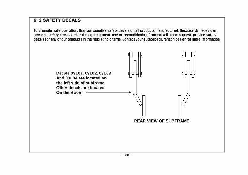
6-2 SAFETY DECALS
To promote safe operation, Branson supplies safety decals on all products manufactured. Because damages can
occur to safety decals either through shipment, use or reconditioning, Branson will, upon request, provide safety
decals for any of our products in the field at no charge. Contact your authorized Branson dealer for more information.
Decals 03L01, 03L02, 03L03 And 03L04 are located on the left side of subframe. Other decals are located On the Boom
REAR VIEW OF SUBFRAME

- 69 -
03L01
03L02 03L03 03L04

- 70 -
03L05
03L06

- 71 -
6-3 TORQUE SPECIFICATIONS Proper torque for American fasteners used on Branson equipments.
Recommended Torque in Foot Pounds(Newton Meter).*
AMERICAN
Bolt Head Markings
WRENCH
SIZE(IN.) "A"
BOLT DIAMETER
(IN.) "B" AND
THREAD SIZE
SAE
GRADE 2
SAE
GRADE 5
SAE
GRADE 8
7/16 1/4 - 20 UNC 6(7) 8(11) 12(16)
7/16 1/4 - 28 UNF 6(8) 10(13) 14(18)
1/2 5/16 - 18 UNC 11(15) 17(23) 25(33)
1/2 5/16 - 24 UNF 13(17) 19(26) 27(37)
9/16 3/8 - 16 UNC 20(27) 31(42) 44(60)
9/16 3/8 - 24 UNF 23(31) 35(47) 49(66)
5/8 7/16 - 14 UNC 32(43) 49(66) 70(95)
5/8 7/16 - 20 UNF 36(49) 55(75) 78(106)
3/4 1/2 - 13 UNC 49(66) 76(103) 106(144)
3/4 1/2 - 20 UNF 55(75) 85(115) 120(163)
7/8 9/16 - 12 UNC 70(95) 109(148) 153(207)
7/8 9/16 - 18 UNF 79(107) 122(165) 172(233)
15/16 5/8 - 11 UNC 97(131) 150(203) 212(287)
15/16 5/8 - 18 UNF 110(149) 170(230) 240(325)
1-1/8 3/4 - 10 UNC 144(195) 266(360) 376(509)
1-1/8 3/4 - 16 UNF 192(260) 297(402) 420(569)
1-5/16 7/8 - 9 UNC 166(225) 430(583) 606(821)
1-5/16 7/8 - 14 UNF 184(249) 474(642) 668(905)
1-1/2 1 - 8 UNC 250(339) 644(873) 909(1232)
1-1/2 1 - 12 UNF 274(371) 705(955) 995(1348)
1-1/2 1 - 14 UNF 280(379) 721(977) 1019(1381)

- 72 -
WRENCH
SIZE(IN.) "A"
BOLT DIAMETER
(IN.) "B" AND
THREAD SIZE
SAE
GRADE 2
SAE
GRADE 5
SAE
GRADE 8
1-11/16 1-1/8 - 7 UNC 354(480) 795(1077) 1288(1745)
1-11/16 1-1/8 - 12 UNF 397(538) 890(1206) 1444(1957)
1-7/8 1-1/4 - 7 UNC 500(478) 1120(1518) 1817(2462)
1-7/8 1-1/4 - 12 UNF 553(749) 1241(1682) 2013(2728)
2-1/16 1-3/8 - 6 UNC 655(887) 1470(1992) 2382(3228)
2-1/16 1-3/8 - 12 UNF 746(1011) 1672(2266) 2712(3675)
2-1/4 1-1/2 - 6 UNC 870(1179) 1950(2642) 3161(4283)
2-1/4 1-1/2 - 12 UNF 979(1327) 2194(2973) 3557(4820) Proper torque for American fasteners used on Branson equipments.
Recommended Torque in Foot Pounds(Newton Meter).*
METRIC WRENCH
SIZE(mm.) "A"
BOLT DIAMETER
(mm.) "B"
ASTM
4.6
ASTM
8.8
ASTM
9.8
ASTM
10.9
8 5 1.8(2.4) 5.1(6.9) 6.5(8.8)
10 6 3(4) 8.7(12) 11.1(15)
13 8 7.3(10) 21.1(29) 27(37)
16 10 14.5(20) 42(57) 53(72)
18 12 25(34) 74(100) 73(99) 93(126)
21 14 40(54) 118(160) 116(157) 148(201)
24 16 62(84) 167(226) 181(245) 230(312)
30 20 122(165) 325(440) 449(608)
33 22 443(600) 611(828)
36 24 211(286) 563(763) 778(1054)
41 27 821(1112) 1138(1542)
46 30 418(566) 1119(1516) 1547(2096) Use 75% of the specified torque value for plated fasteners. Use 85% of the specified torque value for lubricated fasteners

- 73 -
P A R T S M A N U A L
BL25R / BL25R1
Boom Assembly · · · · · · · · · · · · 74
Coupler Assembly · · · · · · · · · · 78
Bucket · · · · · · · · · · · · · · · · · · 80
Mounting Kit · · · · · · · · · · · · · · 82
Bumper Assembly · · · · · · · · · · · 88
Cylinder Assembly · · · · · · · · · · 90
Hydraulic Parts · · · · · · · · · · · · 92
Decal & Manual · · · · · · · · · · · · 100

- 74 -
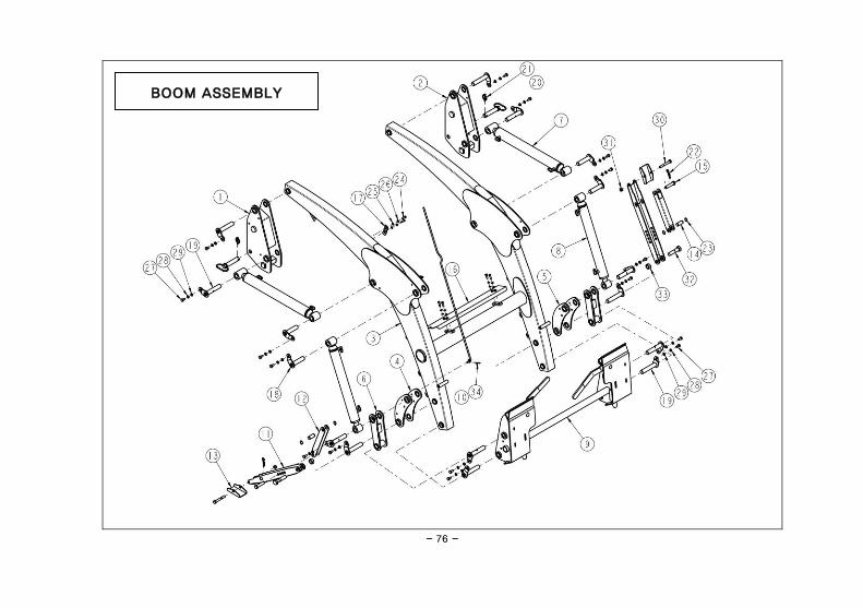
BOOM ASSEMBLY

- 75 -
BOOM ASSEMBLY(P/N: C1850D)
NO PART NUMBER PART NAME DESCRIPTON Q'TY REMARK
1 C1850A-3100 COLUMN, RH. 1
2 C1850A-3200 COLUMN, LH. 1
3 C1850A-0000 BOOM ASSY 1
4 C1850A-6000 LINK BUCKET, RH. 1
5 C1850A-7000 LINK BUCKET, LH. 1
6 C1850A-4100 BUCKET ROD 2
7 C1850D-8000 CYLINDER BOOM Ø55xØ30x690LxST455 2
8 C1850A-9000 BUCKET CYLINDER Ø50xØ30x625LxST390 2
9 B0945B-000B COUPLER B/C 1
10 2540A-450A INDICATOR ASSY 1
11 3045A-8100 STAND 2
12 3045A-8200 BRACKET 4t 2
13 4060A-8400 BRACKET 4t 2
14 4060A-8520 PIN Ø20*48L 2
15 4060A-8530 PIN Ø16*80L 2
16 4060A-7010 COVER 2.3t 1
17 ALN47-07-3100 COVER 4t 1
18 P25A-105A PIN Ø25 4
19 P25A-130A PIN 12
20 P25C-1030 PIN Ø25 2
- 76 -
BOOM ASSEMBLY

- 77 -
BOOM ASSEMBLY(P/N: C1850D)
NO PART NUMBER PART NAME DESCRIPTON Q'TY REMARK
21 AL20-98-9990 LINK PIN 2
22 PR30045 R-PIN Ø3 2
23 SN20M SNAP RING Ø20 4
24 BH0855125Z BOLT M8x25L 6
25 WP08M PLAIN WASHER M8 6
26 WS08M SPRING WASHER M8 6
27 BH1044150Z BOLT(10.9T) M10x20L 16
28 WP10M PLAIN WASHER M10 16
29 WS10M SPRING WASHER M10 16
30 BH12I6175Z BOLT(10.9T) M12x90L 2
31 NL12175Z LOCK NUT M12 2
32 BH20H5250X BOLT(10.9T) M20x85L 2
33 NL20250Z LOCK NUT M20 2
34 PD03025 COTTER PIN Ø3x25L 1

- 78 -
COUPLER ASSEMBLY
- 79 -
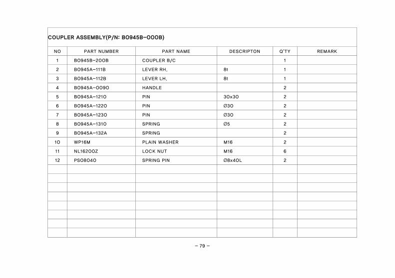
COUPLER ASSEMBLY(P/N: B0945B-000B)
NO PART NUMBER PART NAME DESCRIPTON Q'TY REMARK
1 B0945B-200B COUPLER B/C 1
2 B0945A-111B LEVER RH. 8t 1
3 B0945A-112B LEVER LH. 8t 1
4 B0945A-0090 HANDLE 2
5 B0945A-1210 PIN 30x30 2
6 B0945A-1220 PIN Ø30 2
7 B0945A-1230 PIN Ø30 2
8 B0945A-1310 SPRING Ø5 2
9 B0945A-132A SPRING 2
10 WP16M PLAIN WASHER M16 2
11 NL16200Z LOCK NUT M16 6
12 PS08040 SPRING PIN Ø8x40L 2

- 80 -
BUCKET

- 81 -
BUCKET (P/N:AKU30-A2-0000C)
NO PART NUMBER PART NAME DESCRIPTON Q'TY REMARK
1 AKU30-A2-000C BUCKET L = 1740 1

- 82 -
MOUNTING KIT(K2840C) for BL25R

- 83 -
MOUNTING KIT(P/N:K2840C) for BL25R
NO PART NUMBER PART NAME DESCRIPTON Q'TY REMARK
1 K2840C-1100 SUB FRAME RH 1
2 K2840B-1200 SUB FRAME, RH. 1
3 K2840A-3100 BACK AXLE RH 1
4 K2840A-3200 BACK AXLE LH 1
5 K03B-4000 BUMPER 1
6 C30-09-6100 CROSS BAR 1
7 ALK28-09-416A BUSHING 4
8 BH12P7175Z BOLT(10.9T) M12x125L 4
9 WS12M SPRING WASHER M12 4
10 BH14A7200Z BOLT(10.9T) M14x50L 4
11 WS14M SPRING WASHER M14 4
12 BH1699200Z BOLT(10.9T) M16x45L 8
13 BH16G8200Z BOLT(10.9T) M16x80L 4
14 WS16M SPRING WASHER M16 12
15 NH16200Z NUT M16 4
16 BH20EA250Z BOLT(10.9T) M20x70L 4
17 WP20M PLAIN WASHER M20 4
18 WS20M SPRING WASHER M20 4
19 NH20250Z NUT M20 2

- 84 -
MOUNTING KIT(K2840B) for BL25R1

- 85 -
MOUNTING KIT(P/N:K2840B) for BL25R1
NO PART NUMBER PART NAME DESCRIPTON Q'TY REMARK
1 K2840B-1100 SUB FRAME, RH. 1
2 K2840B-1200 SUB FRAME, RH. 1
3 K2840A-3100 BACK AXLE RH 1
4 K2840A-3200 BACK AXLE LH 1
5 K2840B-1800 C/V BRACKET 1
6 K03B-4000 BUMPER 1
7 C30-09-6100 CROSS BAR 1
8 ALK28-09-416A BUSHING M8x70L 4
9 BH08E6125Z BOLT(10.9T) M8 3
10 WS08M SPRING WASHER M8 3
11 NH08125Z NUT M10x40L 3
12 BH1086150Z BOLT(10.9T) M10 2
13 WS10M SPRING WASHER M10 2
14 NH10150Z NUT M12x125L 2
15 BH12P7175Z BOLT(10.9T) M12 4
16 WS12M SPRING WASHER M14x50L 4
17 BH14A7200Z BOLT(10.9T) M14 4
18 WS14M SPRING WASHER M16x45L 4
19 BH1699200Z BOLT(10.9T) M16 8
20 WS16M SPRING WASHER 12

- 86 -
MOUNTING KIT(K2840B) for BL25R1

- 87 -
MOUNTING KIT(P/N:K2840B) for BL25R1
NO PART NUMBER PART NAME DESCRIPTON Q'TY REMARK
21 BH16G8200Z BOLT(10.9T) M16x80L 4
22 NH16200Z NUT M16 4
23 BH20EA250Z BOLT(10.9T) M20x70L 4
24 WP20M PLAIN WASHER M20 4
25 WS20M SPRING WASHER M20 4
26 NH20250Z NUT M20 2

- 88 -
BUMPER ASSEMBLY

- 89 -
BUMPER ASSEMBLY(P/N:K2840C-4000)
NO PART NUMBER PART NAME DESCRIPTON Q'TY REMARK
1 K2840C-4100 BRACKET LH 1
2 K2840C-4200 BRACKET RH 1
3 K03B-4200 FOLDER 1
4 M7040A-4010 PIN 1
5 WP16M PLAIN WASHER M16 6
6 PD03025 SPLIT PIN Ø3x25L 1
7 WP12M PLAIN WASHER M12 1
8 ALK28-04-0010 SPRING SUP9, Ø1.5xØ18x66L 1
9 WD16M DISC SPRING WASHER M16 2
10 BH16B9200Z BOLT(10.9T) M16x55L 2
11 NL16200Z LOCK NUT M16 2

- 90 -
CYLINDER ASSEMBLY

- 91 -
CYLINDER ASSEMBLY
NO PART NUMBER
PART NAME Q'TY REMARK BUCKET(C1850A-9000) BOOM(C1850D-8000)
10 C1850A-05-1210 C1850D-05-2210 TUBE 1
21 C1850A-05-1110 C1850D-05-2110 ROD 1
31 CR5030 CR5530 COVER ROD 1
32 1BG50 1BG55 O-RING 1
33 1BG44 1BG49 O-RING 1
34 LBW 30x38x5/6.5 LBW 30x38x5/6.5 DUST SEAL 1
35 1BP30 1BP30 O-RING 1
36 ISW 30x40x6 ISW 30x40x6 U-PACKING 1
37 BRWW 30x40x2 BRWW 30x40x2 BACK UP RING 1
38 DU3020 DU3020 DU BUSH 1
40 CY-M20 CY-M20 NUT 1
61 PI5030 PI5530 PISTON 1
62 WRW 50x45x15 WRW 55x50x15 WEAR-RING 1
63 ODW 50x35x9 ODW 55x40x10 U-PACKING 2
64 1BP18 1BP18 O-RING 1
SEAL5030 SEAL5530 SEAL KIT 1

- 92 -
HYDRAULIC PARTS (BL25R)

- 93 -
HYDRAUIC PARTS (BL25R)
NO PART NUMBER PART NAME DESCRIPTON Q'TY REMARK
1 C1850A-07-1100 PIPE 1
2 C1850A-07-1200 PIPE 1
3 C1850A-07-1300 PIEP 1
4 C1850A-07-1400 PIPE 1
5 C1850A-07-1500 PIPE 1
6 C1850A-07-1600 PIPE 1
7 C1850A-07-1700 PIPE 1
8 C1850A-07-1800 PIPE 1
9 5PG1-0300 HOSE ASSY 1
10 5PG1-0760 HOSE ASSY 1
11 5PG1-0060 HOSE ASSY 2
12 5PG1-0050 HOSE ASSY 1
13 5PG1-0140 HOSE ASSY 1
14 5PG1-0480 HOSE ASSY 1
15 5PG1-0570 HOSE ASSY 1
16 5PG1-1840 HOSE ASSY 4
17 ALK28-07-9800 NIPPLE 6
18 ALK28-07-9900 TEE NIPPLE 4
19 ALK28-07-9600 ELBOW NIPPLE 2
20 ALK28-07-7100 Q-COUPLER(F) 4

- 94 -
HYDRAULIC PARTS (BL25R)

- 95 -
HYDRAUIC PARTS (BL25R)
NO PART NUMBER PART NAME DESCRIPTON Q'TY REMARK
21 ALK28-07-7200 Q-COUPER(M) 4
22 ALK28-07-7910 O-RING NIPPLE 2
23 ALK28-07-7920 O-RING NIPPLE 2
24 ALK28-07-9700 ELBOW NEPPLE 4
25 C2050-9500 HOLDER 1
26 BH1066150Z BOLT 1
27 WP10M PLAIN WASHER 1
28 WS10M SPRING WASHER 1
29 NH10150Z NUT 1

- 96 -
HYDRAULIC PARTS (BL25R1)

- 97 -
HYDRAUIC PARTS (BL25R1)
NO PART NUMBER PART NAME DESCRIPTON Q'TY REMARK
1 C1850A-07-1100 PIPE 1
2 C1850A-07-1200 PIPE 1
3 C1850A-07-1300 PIEP 1
4 C1850A-07-1400 PIPE 1
5 C1850A-07-1500 PIPE 1
6 C1850A-07-1600 PIPE 1
7 C1850A-07-1700 PIPE 1
8 C1850A-07-1800 PIPE 1
9 5PG1-0300 HOSE ASSY 1
10 5PG1-0760 HOSE ASSY 1
11 5PG1-0060 HOSE ASSY 2
12 5PG1-0050 HOSE ASSY 1
13 5PG1-0140 HOSE ASSY 1
14 5PG1-0480 HOSE ASSY 1
15 5PG1-0570 HOSE ASSY 1
16 3P81-0900 HOSE ASSY 4
17 ALK28-07-9800 NIPPLE 6
18 ALK28-07-9900 TEE NIPPLE 4
19 ALK28-07-9600 ELBOW NIPPLE 2
20 HDM03/2 CONTROL VALVE 1 BESKO VALVE

- 98 -
HYDRAULIC PARTS (BL25R1)

- 99 -
HYDRAUIC PARTS (BL25R1)
NO PART NUMBER PART NAME DESCRIPTON Q'TY REMARK
21 ALK28-07-7200 Q-COUPLING(M) 4
22 ALK28-07-7100 Q-COUPLING(F) 4
23 AL25-07-9400 O-RING NIPPLE 2
24 AL25-07-940A O-RING NIPPLE 2
25 7860-07-7080 O-RING NIPPLE 2
26 S1600G-07-0010 SWIVEL ELBOW NIPPLE 2
27 M7040-07-7050 O-RING ELBOW 2
28 3P81-1180 HOSE ASSY 1
29 3P81-1200 HOSE ASSY 2
30 BL30-07-7810 NIPPLE 3
31 BL30-07-7820 WASHER(COPPER) 3
- 100 -
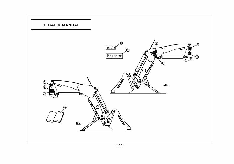
DECAL & MANUAL

- 101 -
DECAL & MANUAL
NO PART NUMBER PART NAME DESCRIPTON Q'TY REMARK
1 03L01 DECAL 1
2 03L02 DECAL 1
3 03L03 DECAL 1
4 03L04 DECAL 1
5 03L05 DECAL 1
6 03L06 DECAL 1
7 03L00 DECAL 1
8 11L20 DECAL 2
9 11L02 DECAL 2
10 M15013 Owner’s MANUAL 1

- 102 -
Memo

- 103 -
INDEX 1

- 104 -
BL25R & BL25R1
PART NO. PAGE PART NO. PAGE PART NO. PAGE
03L00 101 3P81-1200 99 AL20-98-9990 77
03L01 101 4060A-7010 75 AL25-07-9400 99
03L02 101 4060A-8400 75 AL25-07-940A 99
03L03 101 4060A-8520 75 ALK28-04-0010 89
03L04 101 4060A-8530 75 ALK28-07-7100 93
03L05 101 5PG1-0050 93 ALK28-07-7100 99
03L06 101 5PG1-0050 97 ALK28-07-7200 95
11L02 101 5PG1-0060 93 ALK28-07-7200 99
11L20 101 5PG1-0060 97 ALK28-07-7910 95
1BG49 91 5PG1-0140 93 ALK28-07-7920 95
1BG49 91 5PG1-0140 97 ALK28-07-9600 93
1BG55 91 5PG1-0300 93 ALK28-07-9600 97
1BG55 91 5PG1-0300 97 ALK28-07-9700 95
1BP18 91 5PG1-0480 93 ALK28-07-9800 93
1BP18 91 5PG1-0480 97 ALK28-07-9800 97
1BP30 91 5PG1-0570 93 ALK28-07-9900 93
1BP30 91 5PG1-0570 97 ALK28-07-9900 97
2540A-450A 75 5PG1-0760 93 ALK28-09-416A 83
3045A-8100 75 5PG1-0760 97 ALK28-09-416A 85
3045A-8200 75 5PG1-1840 93 ALN47-07-3100 75
3P81-0900 97 7860-07-7080 99 B0945A-0090 79
3P81-1180 99 AKU30-A2-000C 81 B0945A-111B 79

- 105 -
PART NO. INDEX
PART NO. PAGE PART NO. PAGE PART NO. PAGE
B0945A-112B 79 BH16G8200Z 87 C1850A-07-1700 97
B0945A-1210 79 BH20EA250Z 83 C1850A-07-1800 93
B0945A-1220 79 BH20EA250Z 87 C1850A-07-1800 97
B0945A-1230 79 BH20H5250X 77 C1850A-3100 75
B0945A-1310 79 BL30-07-7810 99 C1850A-3200 75
B0945A-132A 79 BL30-07-7820 99 C1850A-4100 75
B0945B-000B 75 BRWW 30x40x2 91 C1850A-6000 75
B0945B-200B 79 BRWW 30x40x2 91 C1850A-7000 75
BH0855125Z 77 C1850A-0000 75 C1850A-9000 75
BH08E6125Z 85 C1850A-07-1100 93 C1850D-05-2110 91
BH1044150Z 77 C1850A-07-1100 97 C1850D-05-2110 91
BH1066150Z 95 C1850A-07-1200 93 C1850D-05-2210 91
BH1086150Z 85 C1850A-07-1200 97 C1850D-05-2210 91
BH12I6175Z 77 C1850A-07-1300 93 C1850D-8000 75
BH12P7175Z 83 C1850A-07-1300 97 C2050-9500 95
BH12P7175Z 85 C1850A-07-1400 93 C30-09-6100 83
BH14A7200Z 83 C1850A-07-1400 97 C30-09-6100 85
BH14A7200Z 85 C1850A-07-1500 93 CR5530 91
BH1699200Z 83 C1850A-07-1500 97 CR5530 91
BH1699200Z 85 C1850A-07-1600 93 CY-M20 91
BH16B9200Z 89 C1850A-07-1600 97 CY-M20 91
BH16G8200Z 83 C1850A-07-1700 93 DU3020 91

- 106 -
BL25R & BL25R1
PART NO. PAGE PART NO. PAGE PART NO. PAGE
DU3020 91 M7040A-4010 89 PS08040 79
HDM03/2 97 NH08125Z 85 S1600G-07-0010 99
ISW 30x40x6 91 NH10150Z 85 SEAL5530 91
ISW 30x40x6 91 NH10150Z 95 SEAL5530 91
K03B-4000 83 NH16200Z 83 SN20M 77
K03B-4000 85 NH16200Z 87 WD16M 89
K03B-4300 89 NH20250Z 83 WP08M 77
K2840A-3100 83 NH20250Z 87 WP10M 77
K2840A-3100 85 NL12175Z 77 WP10M 95
K2840A-3200 83 NL16200Z 79 WP12M 89
K2840A-3200 85 NL16200Z 89 WP16M 79
K2840B-1100 85 NL20250Z 77 WP16M 89
K2840B-1200 83 ODW 55x40x10 91 WP20M 83
K2840B-1200 85 ODW 55x40x10 91 WP20M 87
K2840B-1800 85 P25A-105A 75 WRW 55x50x15 91
K2840C-1100 83 P25A-130A 75 WRW 55x50x15 91
K2840C-4100 89 P25C-1030 75 WS08M 77
K2840C-4200 89 PD03025 77 WS08M 85
LBW 30x38x5/6.5 91 PD03025 89 WS10M 77
LBW 30x38x5/6.5 91 PI5530 91 WS10M 85
M15013 101 PI5530 91 WS10M 95
M7040-07-7050 99 PR30045 77 WS12M 83

- 107 -
PART NO. INDEX
PART NO. PAGE PART NO. PAGE PART NO. PAGE
WS12M 85
WS14M 83
WS14M 85
WS16M 83
WS16M 85
WS20M 83
WS20M 87

- 108 -

- 109 -
INDEX 2

- 110 -
BL25R & BL25R1
PART NAME PAGE PART NAME PAGE PART NAME PAGE
B
BOLT(10.9T) 83 COUPLER B/C 79
BACK AXLE LH 83 BOLT(10.9T) 87 COVER 75
BACK AXLE LH 85 BOLT(10.9T) 77 COVER 75
BACK AXLE RH 83 BOOM ASSY 75 COVER ROD 91
BACK AXLE RH 85 BRACKET 75 COVER ROD 91
BACK UP RING 91 BRACKET 75 CROSS BAR 83
BACK UP RING 91 BRACKET LH 89 CROSS BAR 85
BOLT 77 BRACKET RH 89 CYLINDER BOOM 75
BOLT 95 BUCKET 81 D
BOLT(10.9T) 85 BUCKET CYLINDER 75 DECAL 101
BOLT(10.9T) 77 BUCKET ROD 75 DECAL 101
BOLT(10.9T) 85 BUMPER 83 DECAL 101
BOLT(10.9T) 77 BUMPER 85 DECAL 101
BOLT(10.9T) 83 BUSHING 83 DECAL 101
BOLT(10.9T) 85 BUSHING 85 DECAL 101
BOLT(10.9T) 83 C
DECAL 101
BOLT(10.9T) 85 C/V BRACKET 85 DECAL 101
BOLT(10.9T) 83 COLUMN, LH. 75 DECAL 101
BOLT(10.9T) 85 COLUMN, RH. 75 DISC SPRING WASHER 89
BOLT(10.9T) 89 CONTROL VALVE 97 DU BUSH 91
BOLT(10.9T) 83 COTTER PIN 77 DU BUSH 91
BOLT(10.9T) 87 COUPLER B/C 75 DUST SEAL 91

- 111 -
PART NAME INDEX
PART NAME PAGE PART NAME PAGE PART NAME PAGE
DUST SEAL 91 HOSE ASSY 97 NUT 91
E
HOSE ASSY 93 NUT 91
ELBOW NEPPLE 95 HOSE ASSY 97 NUT 85
ELBOW NIPPLE 93 HOSE ASSY 93 NUT 85
ELBOW NIPPLE 97 HOSE ASSY 97 NUT 95
F
HOSE ASSY 93 NUT 83
FOLDER 89 I
NUT 87
H
INDICATOR ASSY 75 NUT 83
HANDLE 79 L
NUT 87
HOLDER 95 LEVER LH. 79 O
HOSE ASSY 97 LEVER RH. 79 O-RING 91
HOSE ASSY 99 LINK BUCKET, LH. 75 O-RING 91
HOSE ASSY 99 LINK BUCKET, RH. 75 O-RING 91
HOSE ASSY 93 LINK PIN 77 O-RING 91
HOSE ASSY 97 LOCK NUT 77 O-RING 91
HOSE ASSY 93 LOCK NUT 79 O-RING 91
HOSE ASSY 97 LOCK NUT 89 O-RING 91
HOSE ASSY 93 LOCK NUT 77 O-RING 91
HOSE ASSY 97 N
O-RING ELBOW 99
HOSE ASSY 93 NIPPLE 93 O-RING NIPPLE 99
HOSE ASSY 97 NIPPLE 97 O-RING NIPPLE 99
HOSE ASSY 93 NIPPLE 99 O-RING NIPPLE 99

- 112 -
BL25R & BL25R1
PART NAME PAGE PART NAME PAGE PART NAME PAGE
O-RING NIPPLE 95 PIPE 97 R
O-RING NIPPLE 95 PIPE 93 ROD 91
Owner’s MANUAL 101 PIPE 97 ROD 91
P
PIPE 93 R-PIN 77
PIEP 93 PIPE 97 S
PIEP 97 PIPE 93 SEAL KIT 91
PIN 75 PIPE 97 SEAL KIT 91
PIN 75 PISTON 91 SNAP RING 77
PIN 79 PISTON 91 SPLIT PIN 89
PIN 79 PLAIN WASHER 77 SPRING 89
PIN 79 PLAIN WASHER 77 SPRING 79
PIN 89 PLAIN WASHER 95 SPRING 79
PIN 75 PLAIN WASHER 89 SPRING PIN 79
PIN 75 PLAIN WASHER 79 SPRING WASHER 77
PIN 75 PLAIN WASHER 89 SPRING WASHER 85
PIPE 93 PLAIN WASHER 83 SPRING WASHER 77
PIPE 97 PLAIN WASHER 87 SPRING WASHER 85
PIPE 93 Q
SPRING WASHER 95
PIPE 97 Q-COUPER(M) 95 SPRING WASHER 83
PIPE 93 Q-COUPLER(F) 93 SPRING WASHER 85
PIPE 97 Q-COUPLING(F) 99 SPRING WASHER 83
PIPE 93 Q-COUPLING(M) 99 SPRING WASHER 85

- 113 -
PART NAME INDEX
PART NAME PAGE PART NAME PAGE PART NAME PAGE
SPRING WASHER 83 WEAR-RING 91
SPRING WASHER 85 WEAR-RING 91
SPRING WASHER 83
SPRING WASHER 87
STAND 75
SUB FRAME RH 83
SUB FRAME, RH. 85
SUB FRAME, RH. 83
SUB FRAME, RH. 85
SWIVEL ELBOW NIPPLE 99
T
TEE NIPPLE 93
TEE NIPPLE 97
TUBE 91
TUBE 91
U
U-PACKING 91
U-PACKING 91
U-PACKING 91
U-PACKING 91
W
WASHER(COPPER) 99

- 114 -

- 115 -
INDEX 3
- 116 -
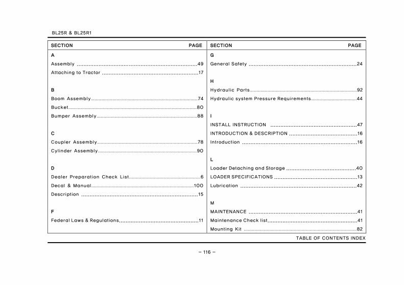
BL25R & BL25R1
SECTION PAGE SECTION PAGE
A G
Assembly ........................................................................49 General Safety .................................................................24
Attaching to Tractor ..........................................................17
H
B Hydraulic Parts………………………………………………………………………………92
Boom Assembly………………………………………………………………………………74 Hydraulic system Pressure Requirements…………………………………44
Bucket………………………………………………………………………………………………80
Bumper Assembly…………………………………………………………………………88 I
INSTALL INSTRUCTION ....................................................47
C INTRODUCTION & DESCRIPTION .........................................16
Coupler Assembly…………………………………………………………………………78 Introduction .....................................................................16
Cylinder Assembly…………………………………………………………………………90
L
D Loader Detaching and Storage ..........................................40
Dealer Preparation Check List……………………………………………………6 LOADER SPECIFICATIONS ..................................................13
Decal & Manual……………………………………………………………………………100 Lubrication ......................................................................42
Description ......................................................................15
M
F MAINTENANCE .................................................................41
Federal Laws & Regulations................................................11 Maintenance Check list......................................................41
Mounting Kit ……………………………………………………………………………………82
TABLE OF CONTENTS INDEX

- 117 -
SECTION PAGE SECTION PAGE
O
OPERATING INSTRUCTIONS ................................................24
Operation .........................................................................24
P
PARTS MANUAL ...............................................................73
PREPARATION FOR USE ......................................................17
S
Safety Decals . .. . . . . . . . .. . . . . . . . . .. . . . . . . . .. . . . . . . . .. . . . . . . .68
Safety Precautions...............................................................7
T
Torque Specifications ........................................................71
Transporting ....................................................................39
Troubleshooting ...............................................................44
W
Warranty ............................................................................4

Part Illustractions included
Branson Front Loader(BL25R Series)
Owner’s Manual
Branson Machinery LLC2100 Cedartown hwy Rome, GA, 30161Tel : 877-734-2022 Fax : 877-734-0637www.bransontractor.com
Part No. M15013Printed in Korea. June 2015
BL25R
Serie
sOWNER'S MANUAL
Branson Front Loader (BL25R Series)
Owner’s Manual
”Œ•£‰…˙¥` 1904.2.1 11:55 PM ˘ ` 1 ˆ •´¨fi ˛˙ˇ……¿ !!