bkpmedia.s3.amazonaws.com€¦ · working quickly, followed by more ... programming language...
TRANSCRIPT
���������������������������������������� ���������� ����� ���������� ����� ���������� ����� ���������� ���������
� ������ ����� ������

CompactLink IC Library Manager Contents
Copyright 2007 B&K Precision Inc i
CONTENTS 1. Preface .....................................................................................................1
1.1. How to use this manual ..................................................................1 1.2. Precautions.....................................................................................1
1.2.1. Host PC ...................................................................................1 1.2.2. Data storage ............................................................................1
1.3. Maintenance ...................................................................................1 1.3.1. Software ..................................................................................1
1.4. Contacting B&K Precision Corporation...........................................2 1.5. Copyright and disclaimers ..............................................................2
2. Introduction...............................................................................................3 2.1. What is CompactLink?....................................................................3
3. Getting started ..........................................................................................4 3.1. Checklist .........................................................................................4 3.2. System requirements......................................................................4 3.3. Installing the security dongle ..........................................................4 3.4. Installing CompactLink ...................................................................5 3.5. Running CompactLink ....................................................................5 3.6. IC library data structure ..................................................................6 3.7. Theory of CompactLink operation...................................................6 3.8. Reviewing the IC library..................................................................6 3.9. Adding an IC to the USER library ...................................................7 3.10. Viewing an IC..................................................................................7 3.11. Copying/editing an IC .....................................................................7 3.12. Specifying a functional test for the IC .............................................8 3.13. Developing a functional test..........................................................10 3.14. Deleting an IC from the USER library ...........................................10 3.15. Printing or exporting a device .......................................................11 3.16. Generating library files..................................................................11
4. Writing your own test programs..............................................................12 4.1. Introduction to PLIP ......................................................................12 4.2. Opening the test development and debugging window ................13 4.3. Entering and compiling a program................................................14 4.4. Fixing the errors and warnings .....................................................15 4.5. Getting help ..................................................................................15 4.6. Documenting your program ..........................................................15 4.7. Connecting to hardware................................................................16
4.7.1. Connecting to B&K 570A/575A products...............................16 4.8. Debugging your program ..............................................................17 4.9. Setting breakpoints .......................................................................18 4.10. Debugging techniques..................................................................19
4.10.1. Compiler errors......................................................................19 4.10.2. Run time errors......................................................................19 4.10.3. Logical errors.........................................................................19
5. Some common programming concepts..................................................22
CompactLink IC Library Manager Contents
Copyright 2007 B&K Precision Inc ii
5.1. Digital test programming...............................................................22 5.1.1. Combinational devices – gates, buffers, multiplexers ...........23 5.1.2. Sequential devices – counters, registers, latches .................23 5.1.3. Tri-state devices – buffers, bus drivers..................................24 5.1.4. LSI and complex devices.......................................................24
5.2. Analog test programming..............................................................25 5.2.1. Using the DRIVE commands .................................................25 5.2.2. Using parameters ..................................................................26
6. 7400 digital IC test program for the B&K 575A.......................................27 6.1. Defining the IC inputs ...................................................................27 6.2. Simple test for a logic NAND gate ................................................27 6.3. Improved logic NAND gate test with looping ................................28 6.4. Complete program for logic NAND gate .......................................29
7. Operational amplifier analog test program for the B&K570A..................32 8. PLIP command and function reference ..................................................37
8.1. Introduction...................................................................................37 9. Troubleshooting and support..................................................................39 10. Appendices ..........................................................................................40
10.1. Library parameter reference .........................................................40 10.2. CompactLink error/warning messages .........................................41 10.3. PLIP error messages ....................................................................44 10.4. PLIP warning messages ...............................................................49 10.5. PLIP run time error messages ......................................................49
11. Index ....................................................................................................51
CompactLink IC Library Manager Preface
Copyright 2007 B&K Precision Inc Page 1
1. Preface Thank you for purchasing the B&K CompactLink IC Library Development Manager software. Please refer to this manual before attempting to install or use the software.
1.1. How to use this manual This manual is divided into sections describing all aspects of CompactLink operation. There is a getting started guide, designed to get you up and working quickly, followed by more detailed instructions on the various functions. We recommend you read at least sections 1 to 3 before using CompactLink for the first time.
This manual is written on the assumption that you are already familiar with the B&K model 570A and/or B&K model 575A products. Please refer to the manuals for those products if you require further information.
This symbol is used where the information given is important to prevent damage to your system or board under test.
1.2. Precautions
1.2.1. Host PC The CompactLink software is designed for use on a PC running Microsoft Windows XP™ software. Operation on any other type of PC or with any other operating system is not supported and may cause problems in use.
1.2.2. Data storage The CompactLink software uses a local database for storing IC details and test programs. Any new ICs you add to the system are stored in the file “B&KCompactLinkICLibrary.dat” in a fixed location – you can open the folder containing the complete IC library database by clicking Start/Program/B&K CompactLink/Database. It is important that this file is backed up regularly to ensure that user devices and test programs are not lost in the event of a hard drive failure.
1.3. Maintenance
1.3.1. Software The CompactLink software is not warranted as being fit for any particular purpose, although B&K will make every effort to ensure that it is suitable for
CompactLink IC Library Manager Preface
Copyright 2007 B&K Precision Inc Page 2
use in conjunction with the B&K model 570A and B&K model 575A products for developing new IC tests.
1.4. Contacting B&K Precision Corporation B&K Precision Corporation 22820 Savi Ranch Parkway Yorba Linda CA 92887-4604
Website: www.bkprecision.com Telephone: 714- 921-9095 Fax: 714-921-6422
1.5. Copyright and disclaimers This manual copyright © 2007 B&K Precision Corp. All rights reserved. First published October 2007.
You may make electronic or paper copies of this manual solely for use in conjunction with operating the software as a bona fide customer, but not for any other purpose.
Windows® and Microsoft® are registered trademarks of Microsoft Corporation.
B&K Precision Corp reserves the right to make product improvements and/or changes at any time without prior notice, including changes to the software specifications. This manual may therefore not necessarily reflect current software specifications.
Whilst B&K Precision Corp makes every effort to ensure the accuracy of this manual, we will not accept liability for damages incurred directly or indirectly from errors, omissions in this manual, or discrepancies between the manual and the CompactLink software itself.
CompactLink IC Library Manager Introduction
Copyright 2007 B&K Precision Inc Page 3
2. Introduction Congratulations on your decision to purchase the CompactLink IC Library Manager software.
2.1. What is CompactLink? CompactLink IC Library Development Manager is designed to allow you to add functional tests for new ICs to the library of your B&K model 570A or 575A IC tester.
The heart of CompactLink is PLIP, which is a high-level descriptive test programming language optimized for generation of both analog and digital IC test programs. Programs are compiled into machine code, making them fast and compact, and can be freely added to the model 570A and 575A libraries. CompactLink contains a sophisticated test program debugger which allows you to check that your program executes correctly before including it in your library.
It is very important to understand that there are two separate functions involved in adding an IC to the user library. Firstly, the IC number, size, pin-out, power supply pins and other information must be defined which will be described in detail later. After this process is complete, you can then write a functional test program, which is the second main function of CompactLink.
CompactLink IC Library Manager Writing test programs
Copyright 2007 B&K Precision Inc Page 4
3. Getting started This section is intended to get CompactLink up and running quickly. Please read carefully before using for the first time. Detailed descriptions of the meaning of the various parameters and device entries will be given later on in the manual
3.1. Checklist The following items are included in the CompactLink package: -
• CompactLink CD • CompactLink USB security dongle • USB to RS-232 converter • Serial connection cable • Operator’s manual
The package may also include FLASH IC(s) for updating of older B&K model 570A or B&K model 575A products.
3.2. System requirements The CompactLink software should be installed on a PC with the following minimum specification: -
• Intel CPU 1GHz or equivalent • 128M RAM • 500MB hard drive space • CD/DVD drive • Free USB port • Microsoft Windows XP™ operating system (service pack 2
recommended) For debugging and library updating, your PC requires a connection to the model 570A or 575A IC tester, to allow test programs to be developed and added to the library. This uses a serial (COM) port (or USB to serial converter).
3.3. Installing the security dongle Before the CompactLink software can be used, the USB security dongle must be installed. The drivers are included on the CompactLink installation CD and must be installed as follows:
• Ensure you are running Windows XP on an account with Administrator privileges.
CompactLink IC Library Manager Writing test programs
Copyright 2007 B&K Precision Inc Page 5
• Insert the CompactLink CD in the CD or DVD drive. • Click “Start, Run, Browse” on your PC and navigate to your CD ROM
drive (usually drive D) with the CompactLink CD inserted. • Select the file “CBUSetup.exe” and click “Open”, then click “OK” to start
the installation. • Follow the instructions on the screen. Once the installation has completed, the USB security token can be inserted into any available USB socket on your computer.
3.4. Installing CompactLink To install the CompactLink software, follow this step by step procedure: -
• Insert the CompactLink CD in your CD or DVD drive. • Click “Start, Run, Browse” on your PC and navigate to your CD ROM
drive (usually drive D) with the CompactLink CD inserted. • Select the file “setup.exe” and click “Open”, then click “OK” to start the
installation. • Follow the installation instructions on the screen. We recommend that all
options are left at their default values.
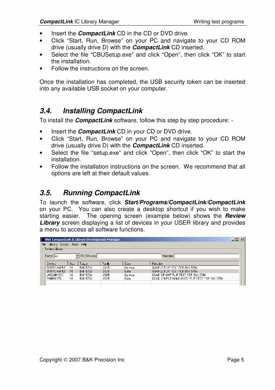
3.5. Running CompactLink To launch the software, click Start/Programs/CompactLink/CompactLink on your PC. You can also create a desktop shortcut if you wish to make starting easier. The opening screen (example below) shows the Review Library screen displaying a list of devices in your USER library and provides a menu to access all software functions.
CompactLink IC Library Manager Writing test programs
Copyright 2007 B&K Precision Inc Page 6
3.6. IC library data structure The data for each IC in the library is organized into Device Information and Target Information. Each device can have one or two targets, each containing target specific information for both products supported by CompactLink (B&K model 570A and B&K model 575A).
The devices in the internal library provided with the product are not included in the CompactLink database but can still be accessed by entering their numbers in the usual way on the unit keypad. See the product manual(s) for a full device listing.
A full list of all device information entries with their meanings is given in appendix 10.1
3.7. Theory of CompactLink operation The following steps are required to add an IC to the library for use on the B&K model 570A or B&K model 575A products. This is a summary – full details are given later in the manual: -
• Add a new device to your USER library using CompactLink • Fill in the device information from the device data sheet • Enable the target product with which you wish to test the device • Fill in the target information for the device/target combination • Enable the functional test for the chosen target product • Choose a test for the device, or develop a new test if no suitable test is
available • Generate the USER library files and download them to the product • The added device is now available in your product device list
3.8. Reviewing the IC library After installation the library will be empty, but as you add ICs they will be displayed in the Library Review table. By default the entire list is shown, but you can restrict the display to a particular Target by using the combo box. If you want to find a particular device, enter its number in the Find Device box. You can also filter the list by entering text in the Function box – the list will be filtered to show only those entries containing the entered text.
You can also sort the list of devices by clicking on any of the column headings in the Library Review display. If you sort on the Device column, by default the full device name is used to sort the entries. However, if you click Tools/Options you can turn on Intelligent Sort, which uses the numeric part of the device name only to produce a more logical list of devices.
CompactLink IC Library Manager Writing test programs
Copyright 2007 B&K Precision Inc Page 7
3.9. Adding an IC to the USER library To add a new IC to the library, choose Device/Add from the menu. You will see the usual Edit Device Definition screen but this time with blank or default entries. On the Device Information tab, fill in the Name and Function boxes and enter suitable values for the other options. The new device defaults to 14 pins, so you may wish to Add or Delete pins with the buttons if the device you are adding has a different number of pins. To change the pin name, click on the pin and enter the new name (maximum 8 characters)
Now you need to choose the product(s) with which the new device is to be tested. For example, if you intend to add this device to the B&K model 575A library, open the B&K 575A Test tab and click Include device in B&K 575A library. You can then set the other entries as you wish. You must enable the functional test checkbox.
3.10. Viewing an IC There are several ways to select a device for viewing: -
• Click on a device in the list and click Device/Edit on the menu • Right click on a device in the list and choose Edit from the popup menu • Double click on a device in the list • Enter all or part of the device name in the Find Device box, then press
the Enter key
In this Edit Device Definition screen you can see the name and function of the device, along with 3 tabs for further device information.
In the Device Information tab you can see the pin out and device specific information such as the package, thresholds and output types. The other tabs contain product specific information.
3.11. Copying/editing an IC You can copy an existing device into your USER library, which is then available for you to edit. As an example of this, carry out the following steps: -
• Return to the Library Review screen by clicking Cancel if you are still looking at a device
• Click on a device in the list • Choose Device/Copy from the menu or right click and select Copy • Enter a new name for the New Device Name and click OK
The new device will then be added to your USER library. Locate it in the library list and double click on it to edit. You can now change the various entries for the device without affecting the original device in the library.
CompactLink IC Library Manager Writing test programs
Copyright 2007 B&K Precision Inc Page 8
On both products there is only a numeric keypad available for entering device numbers. Therefore, on the edit tabs there is a field (Use Number) provided for a numeric part number. For example, if the full part number for a new device is LM339N, you may wish to enter the number 339 in the Use Number field. The B&K 575A and B&K 570A products contain an internal library of IC tests which is not visible in the CompactLink software. When deciding which test to execute, the product software will give priority to the user library if a device with the same number exists. In the above example the 339 new user test for the LM339N will be executed rather than the built-in LM339 test – if you wish to have both tests available use a different number (e.g. 3390) for the user test.
3.12. Specifying a functional test for the IC If you have enabled Functional testing for your newly added device, you have to specify which functional test to use. The actual functional tests are stored separately from the devices since several devices with comparable functions and pin-outs will usually share one test. When you enable Functional testing, you will see in the Functional Test Configuration area that the Current Test entry is blank, showing that as yet no test has been selected for the device.
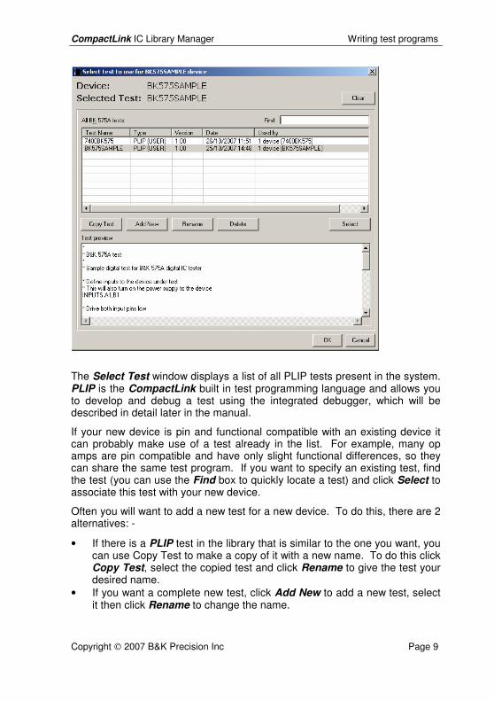
To select a test, click the Select Test button to show the Select Test window as shown below: -
CompactLink IC Library Manager Writing test programs
Copyright 2007 B&K Precision Inc Page 9
The Select Test window displays a list of all PLIP tests present in the system. PLIP is the CompactLink built in test programming language and allows you to develop and debug a test using the integrated debugger, which will be described in detail later in the manual.
If your new device is pin and functional compatible with an existing device it can probably make use of a test already in the list. For example, many op amps are pin compatible and have only slight functional differences, so they can share the same test program. If you want to specify an existing test, find the test (you can use the Find box to quickly locate a test) and click Select to associate this test with your new device.
Often you will want to add a new test for a new device. To do this, there are 2 alternatives: -
• If there is a PLIP test in the library that is similar to the one you want, you can use Copy Test to make a copy of it with a new name. To do this click Copy Test, select the copied test and click Rename to give the test your desired name.
• If you want a complete new test, click Add New to add a new test, select it then click Rename to change the name.
CompactLink IC Library Manager Writing test programs
Copyright 2007 B&K Precision Inc Page 10
In all cases, the preview window displays the source code for the selected test to help you choose a suitable test for your device.
To delete a test, select the test and click Delete, but note that you cannot delete a test that is allocated to a device.
3.13. Developing a functional test Test programming and debugging is a complex subject, which we will discuss in detail later. However, to see the required steps, follow the procedure below: -
• If you have not already done so, add a new device to your USER library as described above
• Define the pin names for the new device, since they are required for the functional test
• Enable the device for the chosen target product as described above • Enable the functional test for the device/target combination • Click Select Test and add a new functional test for the device • Click Develop Test to enter the functional test development and
debugging window • In the Source Program window, enter the PLIP code for the test (full
details later) • Use the toolbar Build Test button to compile the test and fix any
compilation errors • Connect up your chosen hardware (B&K model 575 or 570 tester) • Choose Tools/Configure Hardware and specify the type of hardware
interface to be used • Use the toolbar Send Test button to download the compiled test to the
target hardware • Use the debugging commands and windows to step though the test and
confirm that it executes correctly • Once complete, save the test and close the debugging window • Generate a new set of USER library files containing the new test
3.14. Deleting an IC from the USER library There are two ways to delete a device from your USER library: -
• Select the device to be deleted in the Library Review screen by clicking on it or by entering all or part of its name in the Find box
• Right click on the device and choose Delete, or • Choose Device/Delete from the menu
Once you have deleted a device, there is no way to restore it except by re-entering all its information. You should make regular backups of the database

CompactLink IC Library Manager Writing test programs
Copyright 2007 B&K Precision Inc Page 11
file (B&KCompactLinkICLibrary.dat) to ensure you do not lose wanted data. You can open the folder containing the complete IC library database by clicking Start/Program/B&K CompactLink/Database.
3.15. Printing or exporting a device If you wish to have a hard copy record of a device you can create a report and then either print the report or save it to a text file. To do this, select the device in the Library Review screen and select Device/Print/Export from the menu, or alternatively right click on the device and choose Print/Export. In the report window which appears, you then have the choice between Export, which saves the device details as a text file, and Print, which sends the details to your printer.
3.16. Generating library files Once you have completed adding devices and/or tests, you will probably want to generate a set of library files to include the new device in the library of your product. There are 2 options which can be selected from the Library menu: -
• Update B&K 575A User Library. This produces a B&K 575A user library file (BK575ALIB.CML file) which can be downloaded and programmed into your B&K 575A over the serial cable.
• Update B&K 570A User Library. This produces a B&K 570A user library file (BK570ALIB.LML file) which can be downloaded and programmed into your B&K 570A over the serial cable.
As an example, assume we are going to generate a user library file for the B&K 570A. Choose Library/Update B&K 570A User Library from the menu and the Update Library window appears as follows (assuming the B&K 570A is actually connected to the COM1 port as shown): -
CompactLink IC Library Manager Writing test programs
Copyright 2007 B&K Precision Inc Page 12
The process has 4 stages enabled by the 4 check boxes as follows: -
• Firstly, you must compile all your user tests. The integrated debugger uses a different format for compiled tests to allow easy debugging, so all tests need to be recompiled at this stage. Select the Recompile Tests check box to enable the compiler to compile all B&K 570A tests.
• Enable the Build library file check box to generate the library file for the selected product. In this case the file BK570ALIB.LML will be generated in the folder specified by the Tools/Options menu function.
• If you want to create a backup of any existing user library files, enable the Backup existing files check box. A backup folder will be created and the existing library file(s) will be copied to it before being overwritten with the new file(s).
• If you have a product connected enable the Download library file on success check box. This will cause the generated file(s) to be automatically downloaded to the product provided the compilation and file generation processes executed correctly.
• If you have previously generated a library file using the above procedure, you can enable the Update from existing file check box to skip the compilation and building stages and just download the previously generated file.
Once you have done this you can disconnect the product from CompactLink and the ICs will then be available in the user library.
4. Writing your own test programs
4.1. Introduction to PLIP Once you have added a device to the library you can also add a functional test to the device to perform a truth table or analog (depending on the target product and the device type) test on the device. Functional tests for both target products are written in a high-level programming language called PLIP.
The PLIP test programming language is a high-level language designed specifically for test programming. The syntax is highly descriptive, so that programs are to a large extent self-commenting, but of course comments can be inserted if required. IC pins are referred to by their names (as defined by the IC device information) to avoid continual reference to the pin-out during programming, and to make the programs more readable. In addition, related sets of pins can be defined as a pin group, which can then be referred to by its group name. This again greatly improves the readability and understanding of a test program. See the SET command for further details of this facility.
CompactLink IC Library Manager Writing test programs
Copyright 2007 B&K Precision Inc Page 13
The compiler generates binary data which can be executed in stand alone form by the integral debugger, or combined into library files for use with your B&K 570A or B&K 575A products. The product software contains advanced run time error checking traps to ensure that execution errors (e.g. divide by zero, stack overflow, out of range voltages etc) do not cause system crashes.
Any PLIP program contains a combination of COMMANDS, FUNCTIONS and VARIABLES, the meaning of which will become clear if you work through the development example for the 7400 IC given below.
4.2. Opening the test development and debugging window
The first step in writing any test program is to add a new IC to the library and add a new test for it, as follows: -
• Refer to section 3.9 and add a new device to the library. Enter the name “TESTDEV” in the name field.
• Note that by default the device has 14 pins which have the default names PIN1, PIN2 etc.
• Click on the B&K 570A or B&K 575A test tab depending on the product you wish to connect.
• Enable the Include device in library and Functional Test for the chosen target product.
• Click Select Test to open the Select Test window. • Click Add New to insert a new, blank test and change its name to
TESTDEV. • Click OK to close the Select Test window. • In the Edit Device window, click Develop Test to open the test
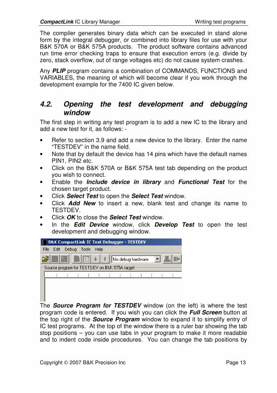
development and debugging window.
The Source Program for TESTDEV window (on the left) is where the test program code is entered. If you wish you can click the Full Screen button at the top right of the Source Program window to expand it to simplify entry of IC test programs. At the top of the window there is a ruler bar showing the tab stop positions – you can use tabs in your program to make it more readable and to indent code inside procedures. You can change the tab positions by

CompactLink IC Library Manager Writing test programs
Copyright 2007 B&K Precision Inc Page 14
choosing Tools/Options/Formatting from the menu or Options from the toolbar, and entering a new Tab width value from 2 to 8. While entering
the test program, you can click the Save Test button on the toolbar to save the current program in the database. You can also write the program to
a text file, or read in a text file, using the Write Test and Load Test buttons on the debug toolbar. These functions allow you, if you wish, to write programs in text format using an external text editor before reading them into the CompactLink debugger.
The debug window also contains menu commands and toolbar buttons for compiling and downloading the test, executing and stepping programs, setting breakpoints and watch values. The meaning of these will become clear as you work through the example 7400 test later on.
4.3. Entering and compiling a program Before starting to work on a real program, we will first have a look at the operation of the editing and compilation system used for PLIP programs. In the Source Program window, type in the following PLIP program: -
A = 0 B = A - D C = A + E
Compile the program by clicking the Build Test button and observe the results. At the bottom left in the Info window, you will see that the compilation failed with 2 errors and 1 warning as follows
CompactLink IC Library Manager Writing test programs
Copyright 2007 B&K Precision Inc Page 15
4.4. Fixing the errors and warnings This is a simple program using variables and expressions. The variables A, B and C are defined, but the variables D and E have not been defined yet are used in expressions. This is an error as the compiler shows. CompactLink allows you to quickly find the errors in your program – click on the error message in the Errors tab in the Info window and observe that the line in the Source Program window containing the error is highlighted. You can also
use the Next Problem/Previous Problem buttons to locate the errors in your program.
The program also has a warning that you have not included an END TEST command – this is required for every PLIP program because the end of the program may not necessarily be at the end of the text if procedures are defined later in your program.
To fix the errors and warnings, amend the program as follows and recompile: -
A = 0 D = 1 E = 2 B = A - D C = A + E END TEST
You should now have a result with no errors and no warnings.
4.5. Getting help CompactLink contains extensive on-line syntax help for PLIP programs. To access this, right click on the program text in the Source Program window and select Syntax Help from the popup menu. CompactLink will attempt to find help for the word you have clicked on and will display the correct syntax with examples. When the PLIP Syntax Guide is open, you can choose other commands from the combo boxes at the top to learn about all the PLIP statements.
Note that if the chosen word in the program has more than one context, you will be given a list of alternatives to choose from. Help is not available for comment lines or unrecognized words. You can also press F1 or choose Help/Syntax from the menu.
4.6. Documenting your program Although PLIP is a very readable language, it is not always clear what the intention of the program is. This is especially true for someone who has not
CompactLink IC Library Manager Writing test programs
Copyright 2007 B&K Precision Inc Page 16
written the program but has to update or modify it. To help with this you can add comments to your program to explain, in your own language, what the program is designed to do. To add a comment, type a * character followed by a description of the program function. The above simple program could be commented as follows: -
* Sample program to show variable definition and expression use * Define variables A, D, E and initialize A = 0 D = 1 E = 2 * Define variables B and C and initialize with expressions B = A - D C = A + E * Tell PLIP this is the end of the test END TEST
You can also include blank lines to separate out blocks of code to further improve readability.
4.7. Connecting to hardware Up to now we have used the CompactLink software alone with no connection to any form of test hardware. However, to debug programs you need a hardware connection to the test product of your choice, using a serial cable to connect to a COM port on your PC. A USB port can be used with the USB to serial converter supplied.
4.7.1. Connecting to B&K 570A/575A products Follow these steps to configure your CompactLink software to connect to your product: -
• If you have not already done so, install the CompactLink software on the PC which is controlling your product(s).
• Connect your B&K 570A or 575A to a battery eliminator, turn on and select CmLink mode (See product manual).
• Connect your product to a COM port on your PC, either directly or to a USB port via the USB-RS232 converter supplied.
• Run the CompactLink software and choose Tools/Configure Hardware from the main menu or from within the test development and debugging window.
• Click Add to add a serial hardware interface.

CompactLink IC Library Manager Writing test programs
Copyright 2007 B&K Precision Inc Page 17
• Select a port for the interface using the Port combo box depending on the COM port used for the serial connection.
• Select the newly added interface by clicking and click Settings. Confirm that the serial port settings are Baud rate: 38400, Data bits: 8, Stop bits: 1, Parity: None, Handshaking: Hardware.
• The Status will be automatically updated by CompactLink and will show Found if the selected interface is present on your system.
• Click Refresh to update the list of attached products. Confirm that the list is correct for your configuration.
• If you wish you can click Test to run the diagnostics on the attached product. The result is displayed in the list.
• Click OK to save the hardware configuration.
4.8. Debugging your program No matter how skilful you are as a programmer, inevitably your program will have problems (commonly called “bugs”) in it. The purpose of the debugger is to help you identify these problems and fix them before adding the test to your library. As an exercise in using the debugger, enter the short program as described in sections 4.3 to 4.5 above, then carry out the following steps: -
• Compile the program by clicking the Build Test button.
• Send the compiled test program to the hardware by clicking the Send Test button. You should then see the following display: -
CompactLink IC Library Manager Writing test programs
Copyright 2007 B&K Precision Inc Page 18
• The 4 execution buttons Execute, Step In, Step Over and Reset are now enabled, and the current execution line (A = 0) is highlighted.
• A further button Stop is displayed but not yet enabled. This enables a running program to be stopped, and is only enabled during program execution.
• Note that the 5 variables A to E are listed in the Variables debug tab on the right, but the values are shown as “---“ since we have not yet executed the program.
• Click the Step In button to step the program. Notice that the variable values are now updated and the execution line moves on to the next line (D = 1). If you hover your mouse pointer over any of the variables in the Source Program window, the value will be shown.
• Continue stepping the program and observe the variables updating as the program executes.
4.9. Setting breakpoints Stepping through the simple program above is easy enough, but for more complex programs it can take a long time to step through the entire program. Breakpoints are up to 3 defined locations in your program where execution can be suspended to allow you to examine variables, check voltages etc. You
can then execute the program and full speed with the Execute button, and the program will stop at the first breakpoint encountered. To set a breakpoint, do the following: - • Click on the line where you want to set the breakpoint, e.g. B = A – D • Choose Debug/Toggle Breakpoint from the menu, or press F9, or right
click and choose Toggle Breakpoint from the popup menu. The selected line will be bulleted to indicate the breakpoint and an entry will be made in the Break debug window on the right
• Click Reset to reset the program back to the start, then click Execute to run the program. You will see that the program stops at the selected line.
• You can now examine the variables to confirm that the program has executed correctly.
CompactLink IC Library Manager Writing test programs
Copyright 2007 B&K Precision Inc Page 19
Note that the Break debug window includes two special breakpoints which are enabled by default but you can turn them off if you wish: -
• Break on first FAIL. This can be useful when writing IC tests since you can run the program until the test fails, allowing you to quickly “home in” on problems in your program.
• Break at end of test. This causes execution to stop at the end of the program. This allows the final state of all program variables to be examined before the test completes.
To remove a breakpoint, click on the line where the breakpoint has been set and choose Toggle Breakpoint again to remove it.
4.10. Debugging techniques Debugging programs is a complex skill that requires practice and experience. Nevertheless there are some ground rules you can follow to help you avoid errors in your programs.
There are 3 types of errors that can occur in your program: -
4.10.1. Compiler errors Compiler errors occur if you mistype text or use incorrect syntax. These are easily fixed as the PLIP compiler provides error messages and the syntax guide helps you get the command right.
4.10.2. Run time errors Run time errors are caused by illegal operations such as divide by zero which cannot be detected by the compiler as it has no knowledge of the intended values of variables in your program. For example, if your program includes the line GAIN = OUTPUT / INPUT you should ensure that the value of INPUT cannot contain zero. This could be done simply as follows: -
IF INPUT <> 0 GAIN = OUTPUT / INPUT END IF
If a run time error occurs, program execution will stop and the cause of the error will be displayed in the Result window at the bottom right.
4.10.3. Logical errors These are the most common type of errors in the program and also the most difficult to find. The following techniques will help: -
• Single step your entire program. This can be laborious but it will ensure your program executes according to plan. Use the Variables window and
CompactLink IC Library Manager Writing test programs
Copyright 2007 B&K Precision Inc Page 20
the automatic mouse hover variable display to confirm that the variables have the correct values.
• Break up your program into PROCEDURES with well-defined input and output values, which can be tested in isolation. Once you have fully
tested a procedure, you can use Step Over to execute calls to it without stepping into the procedure itself, which reduces the amount of stepping you need to do.
• Consider what happens in your test if unusual circumstances are present. For example, if you are reading a voltage from an IC pin, remember that a faulty IC may give unusual voltages, which may upset your program.
• Ensure that you thoroughly understand the function of the IC you are testing. You will be unable to write a functional test program if you do not know how the IC will react to input signals, so obtain an up to date data sheet for the device.
• If your program contains complex calculations, split them into several lines using intermediate variables so you can follow the calculation while stepping.
• Ensure you are aware of the order of precedence of operators (see on line syntax guide). For example, consider the program sequence: -
A = -1 B = 5 CONDITION = A < 0 & B > 3
The & operator is a higher order than the relational operators < and >. Therefore the expression is evaluated as: -
CONDITION = (A < (0 & B)) > 3 which is probably not what you expect. To avoid confusion rewrite as: -
CONDITION = (A < 0) & (B > 3) which makes it clear what you are trying to achieve.
• If your program uses loops (e.g. DO WHILE), ensure that the loop condition can eventually become false and your program cannot get stuck in the loop. For example, consider the following loop in a B&K 570A program: -
DO WHILE VOLTAGE(OUTPUT) < 5 DRIVE INCREMENTAL INPUT WITH 0.05 END DO
If the output voltage never exceeds 5V (which could happen, for example, if the IC is faulty) the program will remain in the loop and will get stuck. To avoid this, try the following: -
* Set an execution limit for the loop
CompactLink IC Library Manager Writing test programs
Copyright 2007 B&K Precision Inc Page 21
LOOP_LIMIT = 1000 * Adjust input voltage until output goes above 5V DO WHILE (VOLTAGE(OUTPUT) < 5) & (LOOP_LIMIT > 0) DRIVE INCREMENTAL INPUT WITH 0.05 * Count number of times we go round the loop LOOP_LIMIT = LOOP_LIMIT - 1 END DO
This is far more complex but ensures your program cannot get stuck in a loop. If the loop executes 1000 times the LOOP_LIMIT variable will become zero and the loop will exit. Once you are sure your program is working correctly, you can remove such error trapping code. Note that this uses the & logical operator to combine 2 test conditions for the loop condition – ensure you use the brackets as shown to ensure the
expression is evaluated as you intend. You can use the Stop button to force a breakpoint in a loop which is executing indefinitely.
• Use the DISPLAY command to show debugging information in the Display Output window at the bottom right. For example in the above program, DISPLAY VOLTAGE(OUTPUT), VOLTAGE(INPUT) will show the voltages at the input and output pins so you can see if they are as expected before using them in subsequent calculations, and DISPLAY 1000 - LOOP_LIMIT will show how many times your loop executed before exiting.
• When you have tested parts of your program to your satisfaction, use breakpoints to stop your program execution after the tested parts so you can then use stepping to test the remainder of the program.
Further examples of common program errors are given in the online syntax help.
CompactLink IC Library Manager Examples
Copyright 2007 B&K Precision Inc Page 22
5. Some common programming concepts Although PLIP is a reasonably simple language to use, some of the concepts involved in IC test programming can be quite complex. The basic principle behind any IC test program is quite simple: -
• Stimulate the inputs of the device under test with the correct logic levels or analog voltages.
• Check that the outputs of the device under test respond as expected to the input signals.
• Ensure that the chosen sequence of input signals covers all aspects of device operation.
However, this is not always as simple as it may seem. To make your program as successful as possible, always try to meet these two objectives before you start: -
• Obtain a sample device of the type you wish to test. • Obtain an up to date data sheet for the device.
We will discuss some of these issues in this section.
5.1. Digital test programming Digital test programming is easier than analog test programming. The operation of the devices is better defined and there is less mathematics involved in testing.
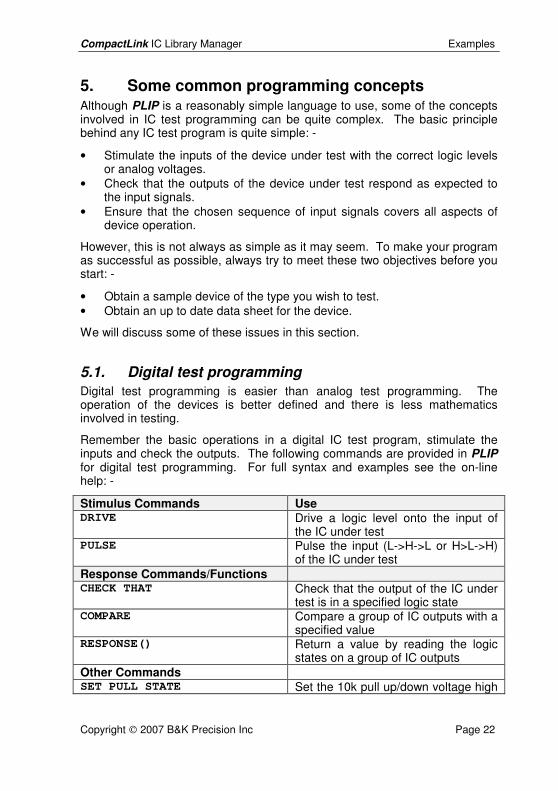
Remember the basic operations in a digital IC test program, stimulate the inputs and check the outputs. The following commands are provided in PLIP for digital test programming. For full syntax and examples see the on-line help: -
Stimulus Commands Use DRIVE Drive a logic level onto the input of
the IC under test PULSE Pulse the input (L->H->L or H>L->H)
of the IC under test Response Commands/Functions CHECK THAT Check that the output of the IC under
test is in a specified logic state COMPARE Compare a group of IC outputs with a
specified value RESPONSE() Return a value by reading the logic
states on a group of IC outputs Other Commands SET PULL STATE Set the 10k pull up/down voltage high
CompactLink IC Library Manager Examples
Copyright 2007 B&K Precision Inc Page 23
or low INPUTS Define the inputs of the IC under test
5.1.1. Combinational devices – gates, buffers, multiplexers Combinational logic devices are the simplest type of logic devices – the output logic levels depend purely on the input logic levels, so your program will probably proceed as follows: -
• Specify the inputs of the IC under test with the INPUTS command • Apply the desired logic levels to the inputs with the DRIVE command • Check that the outputs respond correctly with the CHECK THAT
command
When writing a test for a combinational logic device, ensure that you cover all possible states to get the best test possible. For example, if you are testing a 4 input gate you will need 16 states to cover all combinations of the 4 inputs. This is best achieved with a loop using the DO … WHILE construction to repeat the test with different input states.
5.1.2. Sequential devices – counters, registers, latches Sequential devices are far more complex, and in fact the vast majority of digital devices are sequential. The device normally has one or more clock inputs, and the outputs depend on both the current inputs and on the history of the inputs, so you cannot just apply inputs and check the output response. For example, a 4 bit counter can count from 0 to 15 before starting again at 0. If you just apply a pulse to the clock input using the PULSE command, this will advance the outputs by 1 state, but unless your program knows the initial state you cannot check whether the new state after the clock pulse is correct.
To deal with this problem, there are a number of techniques depending on the type of device: -
• If the device has a clear or reset function, test that first, as then the device will be in a known state.
• If there is no clear or reset function, read the current state of the device outputs using the RESPONSE() function and use that in your program to calculate the next state.
• Some device outputs may not be available externally (e.g. a counter may only have a carry output and the actual counter outputs may not appear externally). In this case you may have to clock the device many times until the carry appears, so that you then know what state the device is in.
In accordance with the above, a typical sequence for a sequential device would be: -
• Specify the inputs of the IC under test with the INPUTS command
CompactLink IC Library Manager Examples
Copyright 2007 B&K Precision Inc Page 24
• Get the device into a known state using a clear or reset input, or issue clock pulses until a known state is reached
• Apply the desired logic levels to the inputs with the DRIVE command • Apply one or more clock pulses depending on the nature of the device • Check that the outputs respond correctly with the CHECK THAT
command
5.1.3. Tri-state devices – buffers, bus drivers Both combinational and sequential devices may have tri-state outputs – these outputs can be turned off or made high impedance by an enable input, so that other devices on a board can drive the pins in a bus structured system. A typical combinational tri-state device test sequence would be as follows: -
• Specify the inputs of the IC under test with the INPUTS command • Drive the enable or chip select input to turn off the tri-state outputs • Check using the SET PULL STATE command that the outputs are
properly turned off • Enable the outputs and apply the desired logic levels to the inputs with
the DRIVE command • Check that the outputs respond correctly with the CHECK THAT
command
For sequential devices with tri-state outputs similar principles apply.
5.1.4. LSI and complex devices Testing complex high pin count devices such as CPUs and CPU peripherals is difficult. In many cases, the device data sheet does not specify exactly how the device responds to the inputs, and there may be minor differences in operation between the same devices from different manufacturers. Some devices may require minimum clock speeds to operate, which means single stepping is impossible. In addition to all this, many devices are so complex that testing every conceivable aspect of device operation may not be feasible because the test would take too long.
Despite this, it is still possible to write tests for complex devices if a few general principles are observed: -
• ICs usually fail because of voltage spikes, static pulses etc on the device pins, so your test should try to ensure every pin is tested in both logic states even if the entire device function cannot be tested
• Many devices need the same sequence of signals repeating many times during a test (for example internal registers that need to be read or written to configure the device operating mode). Use the PROCEDURE … END PROCEDURE construction to write data to registers, so that it can be called from several places in your program
CompactLink IC Library Manager Examples
Copyright 2007 B&K Precision Inc Page 25
• If you cannot determine the exact response of the device outputs from the data sheet, use the following technique: - • Use DRIVE and/or PULSE commands to apply logic levels and
clock pulses to the inputs • Use the DISPLAY command with the RESPONSE() function to
read the output response and display in the text output window in the debugger
• Once you have determined how the IC responds, include CHECK THAT commands to test for the expected response
• If the device will not operate at slow speeds, use the debugger breakpoint system in conjunction with the DISPLAY command to get debugging information about the test
5.2. Analog test programming Analog ICs, by their very nature, are more difficult to test than digital ICs. Consequently analog IC tests are often quite complex, even for very simple components such as transistors and diodes.
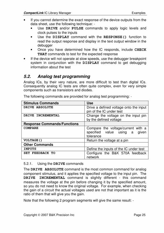
The following commands are provided for analog test programming: -
Stimulus Commands Use DRIVE ABSOLUTE Drive a defined voltage onto the input
pin of the IC under test DRIVE INCREMENTAL Change the voltage on the input pin
by the defined voltage Response Commands/Functions COMPARE Compare the voltage/current with a
specified value using a given tolerance
VOLTAGE() Return the voltage at a pin Other Commands INPUTS Define the inputs of the IC under test SET FEEDBACK TO Configure the B&K 570A feedback
network
5.2.1. Using the DRIVE commands
The DRIVE ABSOLUTE command is the most common command for analog component stimulus, and it applies the specified voltage to the input pin. The DRIVE INCREMENTAL command is slightly different - this command measures the voltage at the pin before changing it by the specified amount, so you do not need to know the original voltage. For example, when checking the gain of a circuit the actual voltages used are not that important as it is the ratio of them that will give you the gain.
Note that the following 2 program segments will give the same result: -
CompactLink IC Library Manager Examples
Copyright 2007 B&K Precision Inc Page 26
DRIVE ABSOLUTE INPUT TO VOLTAGE(INPUT) + 0.1 DRIVE INCREMENTAL INPUT BY 0.1
The first command measures the input voltage and then increases it by 0.1V. The second command does this internally without first measuring the voltage.
5.2.2. Using parameters Parameters are constants used only in B&K 570A tests. They are initialized with values in the Device Information window. This allows many devices with different specifications to share the same test – for example, in a voltage regulator test parameters could be used for the output voltage, tolerance, minimum and maximum currents. This allows the same test to be used for voltage regulators with different output voltages.
To specify parameters, enter PLIP code in the Parameters box in the Device Information window for the device under test. For the above example, the parameters might be entered as follows: -
MIN_CURRENT = 0 MAX_CURRENT = 0.1 SPEC_VOLTAGE = 5 SPEC_TOL = 0.05
When the test is compiled, the given parameters are initialized to the values entered, which can then be used in your program rather than actual numbers, allowing your test to be re-used.
Similar parameters can be used for test voltages and currents in most types of analog tests. For example, the forward voltage drop for a Schottky type diode will be less than a normal silicon diode. A parameter can be used to set the expected voltage drop, which can then be used in your test so that the same diode test can be used for both types of diodes.
CompactLink IC Library Manager Examples
Copyright 2007 B&K Precision Inc Page 27
6. 7400 digital IC test program for the B&K 575A Now we are ready to write a complete IC test program. In this example we will describe how we would write a PLIP test program for a 7400 QUAD NAND GATE IC, and in this way introduce you to the concepts involved in test programming. The program can be executed on the B&K 575A digital IC tester.
6.1. Defining the IC inputs The first step in any test program is to define the input pins of the IC under test, so that the test target product can switch on the drive on these channels. This is achieved using the INPUTS command. Enter the command line into the editing window as follows: -
INPUTS 1A,1B,2A,2B,3A,3B,4A,4B
This command tells CompactLink that the pins listed are all inputs to the IC, and any pins not listed are assumed to be outputs. Note that for test programming purposes power supply pins are assumed to be outputs from the IC under test. You do not need to refer to the pin numbers directly (although you can do so if you wish by using the syntax PIN 1, PIN 3 etc.) because the compiler will substitute the correct numbers from the device information later.
When CompactLink or the target product executes this command line, it will perform various checks on the given pins prior to continuing with the test (depending on the target product). For example, it will check that all the given input pins can be properly driven with valid logic levels. All these checks take place on the first, and only the first, INPUTS command line in your program, so the first INPUTS command should define all the inputs.
We can now go on to drive the input pins for the first gate with a suitable test pattern and check the output, so the program now looks like this: -
INPUTS 1A,1B,2A,2B,3A,3B,4A,4B INPUTS 1A,1B
6.2. Simple test for a logic NAND gate Now we are ready to test the first logic gate in the IC, and to do this we need to drive both inputs with all four possible states according to the truth table for a NAND gate, and check that the output responds accordingly. We could do this with the following program segment: -
DRIVE 1A LOW, 1B LOW CHECK THAT 1Y IS HIGH
CompactLink IC Library Manager Examples
Copyright 2007 B&K Precision Inc Page 28
DRIVE 1A HIGH, 1B LOW CHECK THAT 1Y IS HIGH DRIVE 1A LOW, 1B HIGH CHECK THAT 1Y IS HIGH DRIVE 1A HIGH, 1B HIGH CHECK THAT 1Y IS LOW
6.3. Improved logic NAND gate test with looping Whilst the above program will work, there is a more compact way of achieving the same result using another programming construction, the DO WHILE ... END DO construction. This is a commonly found construction allowing blocks of program code to be repeated until a condition is true. Consider the following program segment: -
DATA = 0 DO WHILE DATA <= 3 DRIVE [1A,1B] WITH DATA IF DATA = 3 CHECK THAT 1Y IS LOW ELSE CHECK THAT 1Y IS HIGH END IF DATA = DATA + 1 END DO
The above loop actually contains slightly more code than the original simple program, but can easily be modified for gates with 3 or more inputs to produce far more compact code. It is of course more complex and introduces several other programming concepts. Firstly, we have now defined a variable, called DATA, which is initialized to the value 0 by the first line in the segment. Variables in PLIP are stored in floating point format and can have values ranging from -32767e-99 to +32767e+99. The variable name itself can have up to 30 alphanumeric characters including underscores, but must begin with a letter.
The second line contains a DO WHILE condition. All the program lines in between the DO WHILE and END DO commands will be executed repeatedly until the condition is false. It follows therefore that the program must contain code to change the condition otherwise the program will stick in an endless loop! In this case, the condition is that the value of DATA must be less than or equal to 3 for the following program lines to be executed. Also here, on line 3 we have introduced a modified form of the DRIVE command, using square brackets ([ ]) to group together the two input pins. This form of the DRIVE command allows a numeric value to be driven in binary form (i.e.
CompactLink IC Library Manager Examples
Copyright 2007 B&K Precision Inc Page 29
1 bit at a time) onto the pins contained in the command. In this case, this means that bit 0 of the variable DATA is driven onto pin 1A, and bit 1 is driven onto pin 1B.
On line 4 we are using an IF ... ELSE ... END IF construction to decide on the expected value of the output logic level depending on the input state. You will see that the above program correctly tests the output pin according to the truth table for a NAND gate – if the value of DATA is 3 (i.e. both inputs high) the output is expected to be low, otherwise it should be high.
Finally, after one run through the test program the value of DATA is incremented by 1, and the END DO command causes execution to return to the DO WHILE command line and repeat the entire program section. This will continue until the value of DATA is 4, when execution will continue after the END DO command line. Notice in both the above two program segments that we have indented, by 4 spaces (or a tab), the code following an IF or a DO WHILE statement, but the relevant ELSE, END IF and END DO commands revert to the original column on the display. This is not necessary for your program to work, but it improves the readability of your program particularly when DO WHILE ... END DO or IF ... ELSE ... END IF blocks are nested inside each other. We suggest you get into the habit of doing this when you write your programs.
6.4. Complete program for logic NAND gate The program to test the first gate in the package now looks like this: -
INPUTS 1A,1B,2A,2B,3A,3B,4A,4B INPUTS 1A,1B DATA = 0 DO WHILE DATA <= 3 DRIVE [1A,1B] WITH DATA IF DATA = 3 CHECK THAT 1Y IS LOW ELSE CHECK THAT 1Y IS HIGH END IF DATA = DATA + 1 END DO
It would be a good idea at this stage to test the program with the debugger to ensure that it functions as expected, before going on to test the other three gates in the package. In this way, if any mistakes are found they can be corrected before continuing with the program entry. However, for completeness, we will now give the complete program for all 4 gates in the
CompactLink IC Library Manager Examples
Copyright 2007 B&K Precision Inc Page 30
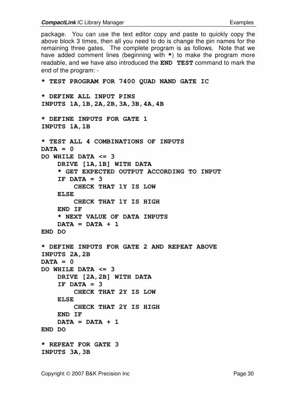
package. You can use the text editor copy and paste to quickly copy the above block 3 times, then all you need to do is change the pin names for the remaining three gates. The complete program is as follows. Note that we have added comment lines (beginning with *) to make the program more readable, and we have also introduced the END TEST command to mark the end of the program: -
* TEST PROGRAM FOR 7400 QUAD NAND GATE IC * DEFINE ALL INPUT PINS INPUTS 1A,1B,2A,2B,3A,3B,4A,4B * DEFINE INPUTS FOR GATE 1 INPUTS 1A,1B * TEST ALL 4 COMBINATIONS OF INPUTS DATA = 0 DO WHILE DATA <= 3 DRIVE [1A,1B] WITH DATA * GET EXPECTED OUTPUT ACCORDING TO INPUT IF DATA = 3 CHECK THAT 1Y IS LOW ELSE CHECK THAT 1Y IS HIGH END IF * NEXT VALUE OF DATA INPUTS DATA = DATA + 1 END DO * DEFINE INPUTS FOR GATE 2 AND REPEAT ABOVE INPUTS 2A,2B DATA = 0 DO WHILE DATA <= 3 DRIVE [2A,2B] WITH DATA IF DATA = 3 CHECK THAT 2Y IS LOW ELSE CHECK THAT 2Y IS HIGH END IF DATA = DATA + 1 END DO * REPEAT FOR GATE 3 INPUTS 3A,3B

CompactLink IC Library Manager Examples
Copyright 2007 B&K Precision Inc Page 31
DATA = 0 DO WHILE DATA <= 3 DRIVE [3A,3B] WITH DATA IF DATA = 3 CHECK THAT 3Y IS LOW ELSE CHECK THAT 3Y IS HIGH END IF DATA = DATA + 1 END DO * REPEAT FOR GATE 4 INPUTS 4A,4B DATA = 0 DO WHILE DATA <= 3 DRIVE [4A,4B] WITH DATA IF DATA = 3 CHECK THAT 4Y IS LOW ELSE CHECK THAT 4Y IS HIGH END IF DATA = DATA + 1 END DO END TEST
If you have not already keyed in this program we suggest you do it now. The program is also included in the test 7400BK575 which is included as a sample user device in the database supplied with the software. After entering the
program, click the Save Test button on the toolbar to save it.
The above is a very simple example of a test program, but it does show some of the main features of the language.
CompactLink IC Library Manager Examples
Copyright 2007 B&K Precision Inc Page 32
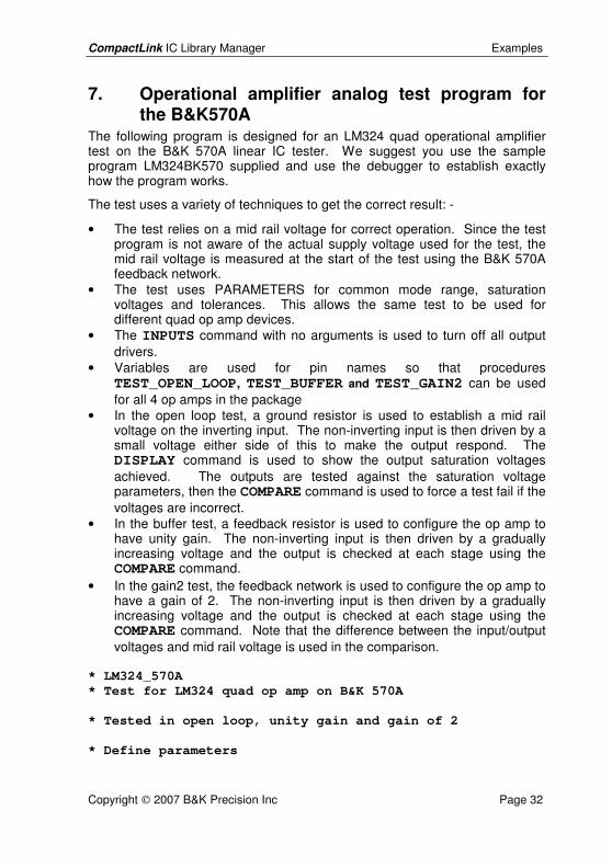
7. Operational amplifier analog test program for the B&K570A
The following program is designed for an LM324 quad operational amplifier test on the B&K 570A linear IC tester. We suggest you use the sample program LM324BK570 supplied and use the debugger to establish exactly how the program works.
The test uses a variety of techniques to get the correct result: -
• The test relies on a mid rail voltage for correct operation. Since the test program is not aware of the actual supply voltage used for the test, the mid rail voltage is measured at the start of the test using the B&K 570A feedback network.
• The test uses PARAMETERS for common mode range, saturation voltages and tolerances. This allows the same test to be used for different quad op amp devices.
• The INPUTS command with no arguments is used to turn off all output drivers.
• Variables are used for pin names so that procedures TEST_OPEN_LOOP, TEST_BUFFER and TEST_GAIN2 can be used for all 4 op amps in the package
• In the open loop test, a ground resistor is used to establish a mid rail voltage on the inverting input. The non-inverting input is then driven by a small voltage either side of this to make the output respond. The DISPLAY command is used to show the output saturation voltages achieved. The outputs are tested against the saturation voltage parameters, then the COMPARE command is used to force a test fail if the voltages are incorrect.
• In the buffer test, a feedback resistor is used to configure the op amp to have unity gain. The non-inverting input is then driven by a gradually increasing voltage and the output is checked at each stage using the COMPARE command.
• In the gain2 test, the feedback network is used to configure the op amp to have a gain of 2. The non-inverting input is then driven by a gradually increasing voltage and the output is checked at each stage using the COMPARE command. Note that the difference between the input/output voltages and mid rail voltage is used in the comparison.
* LM324_570A * Test for LM324 quad op amp on B&K 570A * Tested in open loop, unity gain and gain of 2 * Define parameters
CompactLink IC Library Manager Examples
Copyright 2007 B&K Precision Inc Page 33
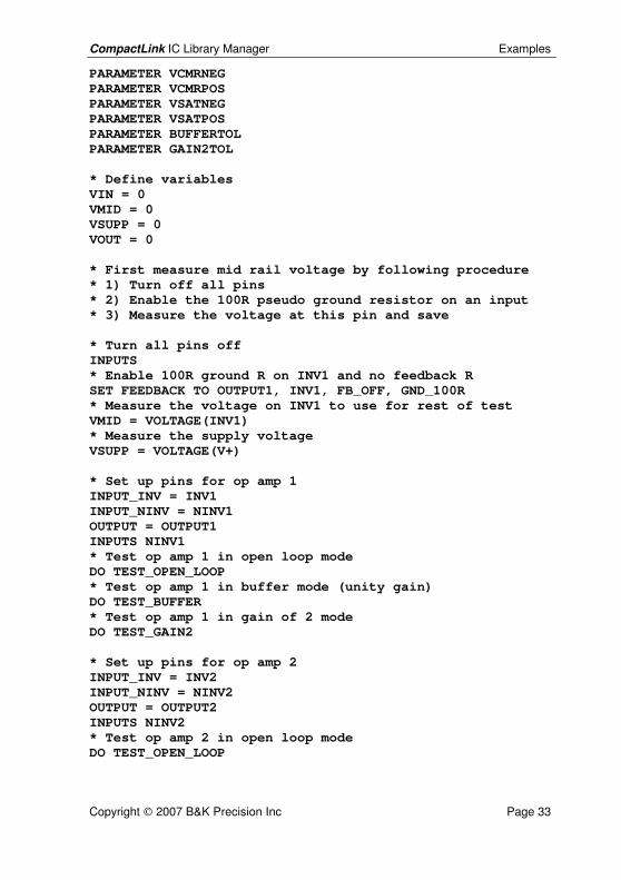
PARAMETER VCMRNEG PARAMETER VCMRPOS PARAMETER VSATNEG PARAMETER VSATPOS PARAMETER BUFFERTOL PARAMETER GAIN2TOL * Define variables VIN = 0 VMID = 0 VSUPP = 0 VOUT = 0 * First measure mid rail voltage by following procedure * 1) Turn off all pins * 2) Enable the 100R pseudo ground resistor on an input * 3) Measure the voltage at this pin and save * Turn all pins off INPUTS * Enable 100R ground R on INV1 and no feedback R SET FEEDBACK TO OUTPUT1, INV1, FB_OFF, GND_100R * Measure the voltage on INV1 to use for rest of test VMID = VOLTAGE(INV1) * Measure the supply voltage VSUPP = VOLTAGE(V+) * Set up pins for op amp 1 INPUT_INV = INV1 INPUT_NINV = NINV1 OUTPUT = OUTPUT1 INPUTS NINV1 * Test op amp 1 in open loop mode DO TEST_OPEN_LOOP * Test op amp 1 in buffer mode (unity gain) DO TEST_BUFFER * Test op amp 1 in gain of 2 mode DO TEST_GAIN2 * Set up pins for op amp 2 INPUT_INV = INV2 INPUT_NINV = NINV2 OUTPUT = OUTPUT2 INPUTS NINV2 * Test op amp 2 in open loop mode DO TEST_OPEN_LOOP
CompactLink IC Library Manager Examples
Copyright 2007 B&K Precision Inc Page 34
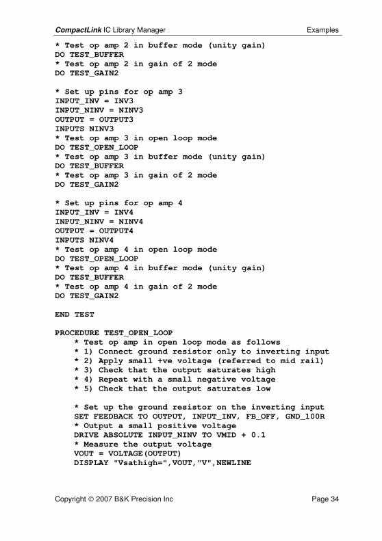
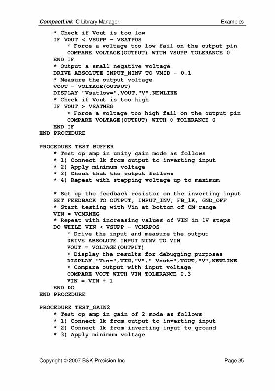
* Test op amp 2 in buffer mode (unity gain) DO TEST_BUFFER * Test op amp 2 in gain of 2 mode DO TEST_GAIN2 * Set up pins for op amp 3 INPUT_INV = INV3 INPUT_NINV = NINV3 OUTPUT = OUTPUT3 INPUTS NINV3 * Test op amp 3 in open loop mode DO TEST_OPEN_LOOP * Test op amp 3 in buffer mode (unity gain) DO TEST_BUFFER * Test op amp 3 in gain of 2 mode DO TEST_GAIN2 * Set up pins for op amp 4 INPUT_INV = INV4 INPUT_NINV = NINV4 OUTPUT = OUTPUT4 INPUTS NINV4 * Test op amp 4 in open loop mode DO TEST_OPEN_LOOP * Test op amp 4 in buffer mode (unity gain) DO TEST_BUFFER * Test op amp 4 in gain of 2 mode DO TEST_GAIN2 END TEST PROCEDURE TEST_OPEN_LOOP * Test op amp in open loop mode as follows * 1) Connect ground resistor only to inverting input * 2) Apply small +ve voltage (referred to mid rail) * 3) Check that the output saturates high * 4) Repeat with a small negative voltage * 5) Check that the output saturates low * Set up the ground resistor on the inverting input SET FEEDBACK TO OUTPUT, INPUT_INV, FB_OFF, GND_100R * Output a small positive voltage DRIVE ABSOLUTE INPUT_NINV TO VMID + 0.1 * Measure the output voltage VOUT = VOLTAGE(OUTPUT) DISPLAY "Vsathigh=",VOUT,"V",NEWLINE
CompactLink IC Library Manager Examples
Copyright 2007 B&K Precision Inc Page 35
* Check if Vout is too low IF VOUT < VSUPP - VSATPOS * Force a voltage too low fail on the output pin COMPARE VOLTAGE(OUTPUT) WITH VSUPP TOLERANCE 0 END IF * Output a small negative voltage DRIVE ABSOLUTE INPUT_NINV TO VMID - 0.1 * Measure the output voltage VOUT = VOLTAGE(OUTPUT) DISPLAY "Vsatlow=",VOUT,"V",NEWLINE * Check if Vout is too high IF VOUT > VSATNEG * Force a voltage too high fail on the output pin COMPARE VOLTAGE(OUTPUT) WITH 0 TOLERANCE 0 END IF END PROCEDURE PROCEDURE TEST_BUFFER * Test op amp in unity gain mode as follows * 1) Connect 1k from output to inverting input * 2) Apply minimum voltage * 3) Check that the output follows * 4) Repeat with stepping voltage up to maximum * Set up the feedback resistor on the inverting input SET FEEDBACK TO OUTPUT, INPUT_INV, FB_1K, GND_OFF * Start testing with Vin at bottom of CM range VIN = VCMRNEG * Repeat with increasing values of VIN in 1V steps DO WHILE VIN < VSUPP - VCMRPOS * Drive the input and measure the output DRIVE ABSOLUTE INPUT_NINV TO VIN VOUT = VOLTAGE(OUTPUT) * Display the results for debugging purposes DISPLAY "Vin=",VIN,"V"," Vout=",VOUT,"V",NEWLINE * Compare output with input voltage COMPARE VOUT WITH VIN TOLERANCE 0.3 VIN = VIN + 1 END DO END PROCEDURE PROCEDURE TEST_GAIN2 * Test op amp in gain of 2 mode as follows * 1) Connect 1k from output to inverting input * 2) Connect 1k from inverting input to ground * 3) Apply minimum voltage

CompactLink IC Library Manager Examples
Copyright 2007 B&K Precision Inc Page 36
* 3) Check that the output follows * 4) Repeat with stepping voltage up to maximum * Set up feedback/ground resistors on inverting input SET FEEDBACK TO OUTPUT, INPUT_INV, FB_1K, GND_1K * Start testing at -1V (referred to mid rail) VIN = VMID - 1 * Repeat with increasing values of VIN in 0.5V steps DO WHILE VIN <= VMID + 1 * Drive the input and measure the output DRIVE ABSOLUTE INPUT_NINV TO VIN VOUT = VOLTAGE(OUTPUT) * Display the results for debugging purposes DISPLAY "Vin=",VIN,"V"," Vout=",VOUT,"V",NEWLINE * Compare output with gain * diff input voltage COMPARE VOUT WITH VMID+2*(VIN-VMID) TOLERANCE 0.3 VIN = VIN + 0.5 END DO END PROCEDURE

CompactLink IC Library Manager Reference
Copyright 2007 B&K Precision Inc Page 37
8. PLIP command and function reference
8.1. Introduction Full details of all PLIP commands and functions are included in the software so you can get help on syntax at any time while developing your program. To access this on line syntax help, do the following: -
• Click in the Source Program window in the word you wish to look up • Choose Help/Syntax from the menu, or right click and choose Syntax
Help from the popup menu, or press F1 • If the selected word appears in several topics, choose the most
applicable topic from the list displayed • The PLIP Syntax Guide will now be displayed
The following words/phrases are used throughout the command/function descriptions: -
expression - a valid expression containing numbers, variables, arithmetic and/or logical operators and functions
condition - an expression that evaluates to either 0 (FALSE) or 1 (TRUE). Usually the expression will include a relational operator (e.g. =, <= etc.) but any expression which gives the result 0 or 1 will work.
pin name - a text string of up to 8 characters giving the name of an IC pin as defined in the IC definition database. Note that you can use the default strings PIN 1, PIN 2 etc. if for some reason you do not wish to use the defined pin names. If the IC pin definition contains several pins with the same name, only the first one will be used by the compiler in programs. The remaining pins MUST be referenced by the text PIN 1, PIN 2 etc..
pin name list - a text string containing a list of up to 8 pin names defined as above. Usually the pin name list will be contained in square brackets [ ].
pin group - a text string that is used as an identifier to refer to a group of pins that are logically connected with each other. The pin group is identified by the use of angular brackets <>. The text string can have a maximum of 30 alphanumeric characters and can contain underscores.
procedure name - a text string which is used as an identifier to refer to a procedure defined in your program. The text string can have a maximum of 30 alphanumeric characters and can contain underscores.
... - this symbol is used in some of the examples to indicate that other, non-specified, program lines are present on these lines.
CompactLink IC Library Manager Reference
Copyright 2007 B&K Precision Inc Page 38
variable name - a text string that is used as an identifier to refer to a variable defined in your program. The text string can have a maximum of 30 alphanumeric characters and can contain underscores. It can also refer to the pre-defined array using the string ARRAY[].
CompactLink IC Library Manager Reference
Copyright 2007 B&K Precision Inc Page 39
9. Troubleshooting and support If you suspect your CompactLink software is not functioning correctly, contact B&K Precision with full details of the apparent problem. We will respond as soon as possible with advice.
CompactLink IC Library Manager Reference
Copyright 2007 B&K Precision Inc Page 40
10. Appendices
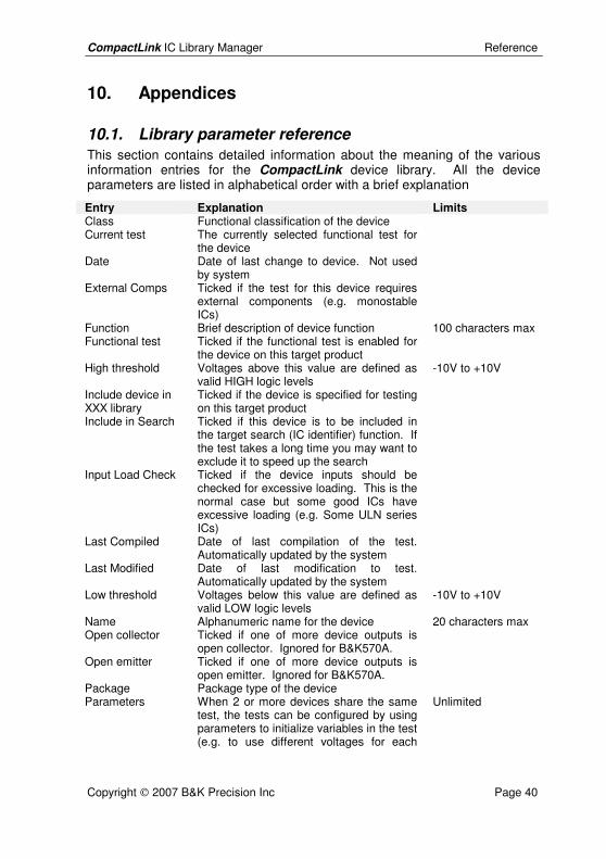
10.1. Library parameter reference This section contains detailed information about the meaning of the various information entries for the CompactLink device library. All the device parameters are listed in alphabetical order with a brief explanation
Entry Explanation Limits Class Functional classification of the device Current test The currently selected functional test for
the device
Date Date of last change to device. Not used by system
External Comps Ticked if the test for this device requires external components (e.g. monostable ICs)
Function Brief description of device function 100 characters max Functional test Ticked if the functional test is enabled for
the device on this target product
High threshold Voltages above this value are defined as valid HIGH logic levels
-10V to +10V
Include device in XXX library
Ticked if the device is specified for testing on this target product
Include in Search Ticked if this device is to be included in the target search (IC identifier) function. If the test takes a long time you may want to exclude it to speed up the search
Input Load Check Ticked if the device inputs should be checked for excessive loading. This is the normal case but some good ICs have excessive loading (e.g. Some ULN series ICs)
Last Compiled Date of last compilation of the test. Automatically updated by the system
Last Modified Date of last modification to test. Automatically updated by the system
Low threshold Voltages below this value are defined as valid LOW logic levels
-10V to +10V
Name Alphanumeric name for the device 20 characters max Open collector Ticked if one of more device outputs is
open collector. Ignored for B&K570A.
Open emitter Ticked if one of more device outputs is open emitter. Ignored for B&K570A.
Package Package type of the device Parameters When 2 or more devices share the same
test, the tests can be configured by using parameters to initialize variables in the test (e.g. to use different voltages for each
Unlimited
CompactLink IC Library Manager Reference
Copyright 2007 B&K Precision Inc Page 41
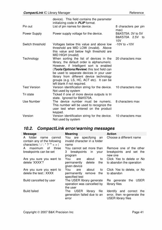
device). This field contains the parameter initializing code in PLIP format.
Pin out List of pin names for device. 8 characters per pin max)
Power Supply Power supply voltage for the device. B&K575A: 3V to 5V B&K570A 2.5V to 10V
Switch threshold Voltages below this value and above low threshold are MID LOW (invalid). Above this value and below high threshold are MID HIGH (invalid)
-10V to +10V
Technology When sorting the list of devices in the library, the default order is alphanumeric. However, if Intelligent sort is enabled (Tools/Options/Review) this text field can be used to separate devices in your user library from different device technology groups (e.g. LS, HC, ACT etc). It can be left blank if not required.
20 characters max
Test Version Version identification string for the device. Not used by system
10 characters max
Tri state Ticked if one of more device outputs is tri state. Ignored for B&K570A.
Use Number The device number must be numeric. This number will be used to recognize the user test when entered on the product keypad.
8 characters max
Version Version identification string for the device. Not used by system
10 characters max
10.2. CompactLink error/warning messages Message Meaning Action A folder name cannot contain any of the following characters: \ / : * ? "" < > |
You are specifying an invalid character in a folder name
Choose a different name
A maximum of three breakpoints can be set
You cannot set more than 3 breakpoints in your program
Remove one of the other breakpoints and set the new one
Are you sure you want to delete ‘XXXX’?
You are about to permanently delete the given device
Click Yes to delete or No to abandon the operation
Are you sure you want to delete the test:: XXXX
You are about to permanently remove the specified test
Click Yes to delete, or No to abandon
Build cancelled by user The USER library generate operation was cancelled by the user
Re generate the USER library files
Build failed The USER library file generation failed due to an error
Identify and correct the error, then re-generate the USER library files

CompactLink IC Library Manager Reference
Copyright 2007 B&K Precision Inc Page 42
Cannot set breakpoint on this line
The selected line is either a comment or has no executable code present (e.g. SET pin group command)
Choose another line for your breakpoint
Error - syntax help for ‘XXXX’ not found
The word under the cursor has no matching syntax help topic
Choose another word
Error - syntax help for this command not found
Missing syntax help for the selected topic
Choose another topic. Contact B&K with details of the problem
Error adding new test There was an error saving the new test details in the database
Contact B&K with details
Error copying test There was an error saving the copied test details in the database
Contact B&K with details
Error loading device There was an error loading the device details from the database
Contact B&K with details
Error loading test There was an error loading the test details from the database
Contact B&K with details
Error saving device There was an error saving the device details in the database
Contact B&K with details
Error saving test There was an error saving the test details in the database
Contact B&K with details
Feature not implemented The selected function is not present in the software
Contact B&K with details
Memory dump size must be between 1 and 12k (3000H) bytes
The size of the displayed memory block must between 1 byte and 12k (12,288) bytes
Change the start and/or stop addresses for the memory dump
Must be numeric value from X to Y
The voltage value being entered is invalid
Re-enter according to the limits given
No devices to build There are no devices in your USER library
Add at least one USER device before continuing
Please enter a test name You are trying to rename a test with a blank test name
Enter a valid name for the test
Program not built or has errors, cannot set breakpoint
You cannot set breakpoints until you have successfully compiled your program
Correct and errors and recompile the program
Search text was not found The text being sought in the program was not found
Re-enter the text to search for
Source has been changed, do you wish to save the changes?
The program source text has been changed. If you exit the debugger now you will lose your changes
Click Cancel and save the changed program before continuing
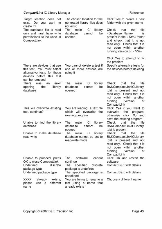
CompactLink IC Library Manager Reference
Copyright 2007 B&K Precision Inc Page 43
Target location does not exist. Do you want to create it?
The chosen location for the generated library files does not exist
Click Yes to create a new folder with the given name
The database file is read only and must have write permissions to be used in CompactLink
The main IC library database cannot be opened
Check that the file «Database_Name» is present in the «Title» folder and check that it is not read only. Check that it is not open within another running version of «Title» Click Yes to attempt to fix the problem
There are devices that use this test. You must select alternative tests for these devices before this test can be removed
You cannot delete a test if one or more devices are using it
Specify alternative tests for the devices before deleting
There was an error opening the library database
The main IC library database cannot be opened
Check that the file B&KCompactLinkICLibrary.dat is present and not read only. Check that it is not open within another running version of CompactLink
This will overwrite existing test, continue?
You are loading a text file which will overwrite the existing program
Click Yes if you want to overwrite the program, otherwise click No and save the existing program
Unable to find the library database
The main IC library database cannot be opened
Check that the file B&KCompactLinkICLibrary.dat is present
Unable to make database read-write
The main IC library database cannot be set to read/write mode
Check that the file B&KCompactLinkICLibrary.dat is present and not read only. Check that it is not open within another running version of CompactLink
Unable to proceed, press OK to close CompactLink
The software cannot continue
Click OK and restart the software
Undefined discrete package type
The specified discrete package is undefined
Contact B&K with details
Undefined package type The specified package is undefined
Contact B&K with details
XXXX already exists, please use a different name
You are trying to rename a test using a name that already exists
Choose a different name
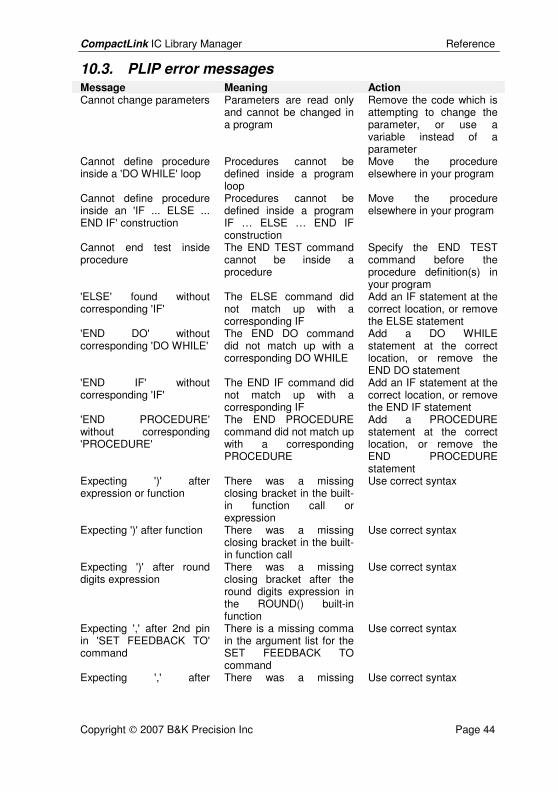
CompactLink IC Library Manager Reference
Copyright 2007 B&K Precision Inc Page 44
10.3. PLIP error messages Message Meaning Action Cannot change parameters Parameters are read only
and cannot be changed in a program
Remove the code which is attempting to change the parameter, or use a variable instead of a parameter
Cannot define procedure inside a 'DO WHILE' loop
Procedures cannot be defined inside a program loop
Move the procedure elsewhere in your program
Cannot define procedure inside an 'IF ... ELSE ... END IF' construction
Procedures cannot be defined inside a program IF … ELSE … END IF construction
Move the procedure elsewhere in your program
Cannot end test inside procedure
The END TEST command cannot be inside a procedure
Specify the END TEST command before the procedure definition(s) in your program
'ELSE' found without corresponding 'IF'
The ELSE command did not match up with a corresponding IF
Add an IF statement at the correct location, or remove the ELSE statement
'END DO' without corresponding 'DO WHILE'
The END DO command did not match up with a corresponding DO WHILE
Add a DO WHILE statement at the correct location, or remove the END DO statement
'END IF' without corresponding 'IF'
The END IF command did not match up with a corresponding IF
Add an IF statement at the correct location, or remove the END IF statement
'END PROCEDURE' without corresponding 'PROCEDURE'
The END PROCEDURE command did not match up with a corresponding PROCEDURE
Add a PROCEDURE statement at the correct location, or remove the END PROCEDURE statement
Expecting ')' after expression or function
There was a missing closing bracket in the built-in function call or expression
Use correct syntax
Expecting ')' after function There was a missing closing bracket in the built-in function call
Use correct syntax
Expecting ')' after round digits expression
There was a missing closing bracket after the round digits expression in the ROUND() built-in function
Use correct syntax
Expecting ',' after 2nd pin in 'SET FEEDBACK TO' command
There is a missing comma in the argument list for the SET FEEDBACK TO command
Use correct syntax
Expecting ',' after There was a missing Use correct syntax
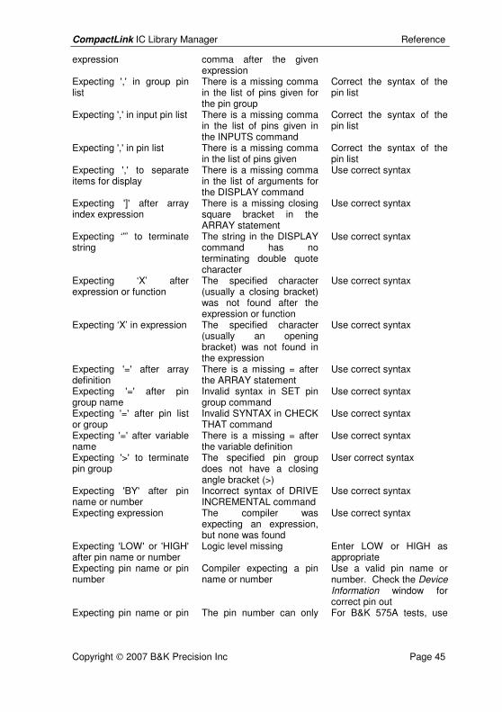
CompactLink IC Library Manager Reference
Copyright 2007 B&K Precision Inc Page 45
expression comma after the given expression
Expecting ',' in group pin list
There is a missing comma in the list of pins given for the pin group
Correct the syntax of the pin list
Expecting ',' in input pin list There is a missing comma in the list of pins given in the INPUTS command
Correct the syntax of the pin list
Expecting ',' in pin list There is a missing comma in the list of pins given
Correct the syntax of the pin list
Expecting ',' to separate items for display
There is a missing comma in the list of arguments for the DISPLAY command
Use correct syntax
Expecting ']' after array index expression
There is a missing closing square bracket in the ARRAY statement
Use correct syntax
Expecting ‘”’ to terminate string
The string in the DISPLAY command has no terminating double quote character
Use correct syntax
Expecting ‘X’ after expression or function
The specified character (usually a closing bracket) was not found after the expression or function
Use correct syntax
Expecting ‘X’ in expression The specified character (usually an opening bracket) was not found in the expression
Use correct syntax
Expecting '=' after array definition
There is a missing = after the ARRAY statement
Use correct syntax
Expecting '=' after pin group name
Invalid syntax in SET pin group command
Use correct syntax
Expecting '=' after pin list or group
Invalid SYNTAX in CHECK THAT command
Use correct syntax
Expecting '=' after variable name
There is a missing = after the variable definition
Use correct syntax
Expecting '>' to terminate pin group
The specified pin group does not have a closing angle bracket (>)
User correct syntax
Expecting 'BY' after pin name or number
Incorrect syntax of DRIVE INCREMENTAL command
Use correct syntax
Expecting expression The compiler was expecting an expression, but none was found
Use correct syntax
Expecting 'LOW' or 'HIGH' after pin name or number
Logic level missing Enter LOW or HIGH as appropriate
Expecting pin name or pin number
Compiler expecting a pin name or number
Use a valid pin name or number. Check the Device Information window for correct pin out
Expecting pin name or pin The pin number can only For B&K 575A tests, use
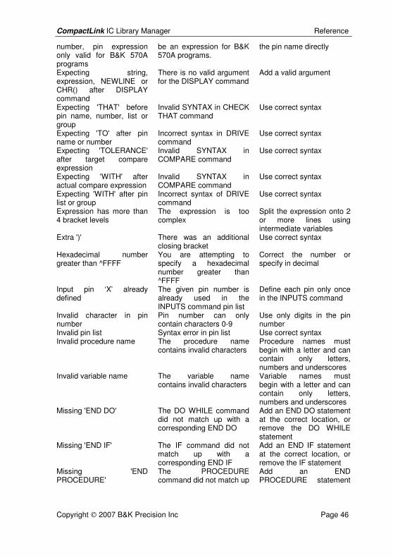
CompactLink IC Library Manager Reference
Copyright 2007 B&K Precision Inc Page 46
number, pin expression only valid for B&K 570A programs
be an expression for B&K 570A programs.
the pin name directly
Expecting string, expression, NEWLINE or CHR() after DISPLAY command
There is no valid argument for the DISPLAY command
Add a valid argument
Expecting 'THAT' before pin name, number, list or group
Invalid SYNTAX in CHECK THAT command
Use correct syntax
Expecting 'TO' after pin name or number
Incorrect syntax in DRIVE command
Use correct syntax
Expecting 'TOLERANCE' after target compare expression
Invalid SYNTAX in COMPARE command
Use correct syntax
Expecting 'WITH' after actual compare expression
Invalid SYNTAX in COMPARE command
Use correct syntax
Expecting 'WITH' after pin list or group
Incorrect syntax of DRIVE command
Use correct syntax
Expression has more than 4 bracket levels
The expression is too complex
Split the expression onto 2 or more lines using intermediate variables
Extra ')' There was an additional closing bracket
Use correct syntax
Hexadecimal number greater than ^FFFF
You are attempting to specify a hexadecimal number greater than ^FFFF
Correct the number or specify in decimal
Input pin ‘X’ already defined
The given pin number is already used in the INPUTS command pin list
Define each pin only once in the INPUTS command
Invalid character in pin number
Pin number can only contain characters 0-9
Use only digits in the pin number
Invalid pin list Syntax error in pin list Use correct syntax Invalid procedure name The procedure name
contains invalid characters Procedure names must begin with a letter and can contain only letters, numbers and underscores
Invalid variable name The variable name contains invalid characters
Variable names must begin with a letter and can contain only letters, numbers and underscores
Missing 'END DO' The DO WHILE command did not match up with a corresponding END DO
Add an END DO statement at the correct location, or remove the DO WHILE statement
Missing 'END IF' The IF command did not match up with a corresponding END IF
Add an END IF statement at the correct location, or remove the IF statement
Missing 'END PROCEDURE'
The PROCEDURE command did not match up
Add an END PROCEDURE statement
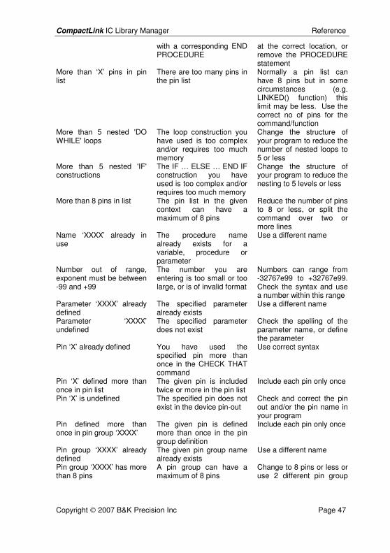
CompactLink IC Library Manager Reference
Copyright 2007 B&K Precision Inc Page 47
with a corresponding END PROCEDURE
at the correct location, or remove the PROCEDURE statement
More than ‘X’ pins in pin list
There are too many pins in the pin list
Normally a pin list can have 8 pins but in some circumstances (e.g. LINKED() function) this limit may be less. Use the correct no of pins for the command/function
More than 5 nested 'DO WHILE' loops
The loop construction you have used is too complex and/or requires too much memory
Change the structure of your program to reduce the number of nested loops to 5 or less
More than 5 nested 'IF' constructions
The IF … ELSE … END IF construction you have used is too complex and/or requires too much memory
Change the structure of your program to reduce the nesting to 5 levels or less
More than 8 pins in list The pin list in the given context can have a maximum of 8 pins
Reduce the number of pins to 8 or less, or split the command over two or more lines
Name ‘XXXX’ already in use
The procedure name already exists for a variable, procedure or parameter
Use a different name
Number out of range, exponent must be between -99 and +99
The number you are entering is too small or too large, or is of invalid format
Numbers can range from -32767e99 to +32767e99. Check the syntax and use a number within this range
Parameter ‘XXXX’ already defined
The specified parameter already exists
Use a different name
Parameter ‘XXXX’ undefined
The specified parameter does not exist
Check the spelling of the parameter name, or define the parameter
Pin ‘X’ already defined You have used the specified pin more than once in the CHECK THAT command
Use correct syntax
Pin ‘X’ defined more than once in pin list
The given pin is included twice or more in the pin list
Include each pin only once
Pin ‘X’ is undefined The specified pin does not exist in the device pin-out
Check and correct the pin out and/or the pin name in your program
Pin defined more than once in pin group ‘XXXX’
The given pin is defined more than once in the pin group definition
Include each pin only once
Pin group ‘XXXX’ already defined
The given pin group name already exists
Use a different name
Pin group ‘XXXX’ has more than 8 pins
A pin group can have a maximum of 8 pins
Change to 8 pins or less or use 2 different pin group
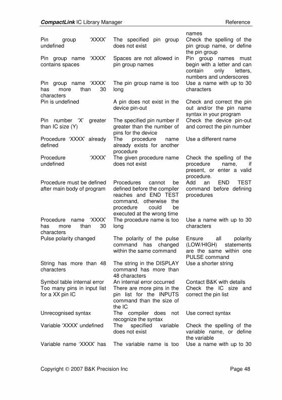
CompactLink IC Library Manager Reference
Copyright 2007 B&K Precision Inc Page 48
names Pin group ‘XXXX’ undefined
The specified pin group does not exist
Check the spelling of the pin group name, or define the pin group
Pin group name ‘XXXX’ contains spaces
Spaces are not allowed in pin group names
Pin group names must begin with a letter and can contain only letters, numbers and underscores
Pin group name ‘XXXX’ has more than 30 characters
The pin group name is too long
Use a name with up to 30 characters
Pin is undefined A pin does not exist in the device pin-out
Check and correct the pin out and/or the pin name syntax in your program
Pin number ‘X’ greater than IC size (Y)
The specified pin number if greater than the number of pins for the device
Check the device pin-out and correct the pin number
Procedure ‘XXXX’ already defined
The procedure name already exists for another procedure
Use a different name
Procedure ‘XXXX’ undefined
The given procedure name does not exist
Check the spelling of the procedure name, if present, or enter a valid procedure.
Procedure must be defined after main body of program
Procedures cannot be defined before the compiler reaches and END TEST command, otherwise the procedure could be executed at the wrong time
Add an END TEST command before defining procedures
Procedure name ‘XXXX’ has more than 30 characters
The procedure name is too long
Use a name with up to 30 characters
Pulse polarity changed The polarity of the pulse command has changed within the same command
Ensure all polarity (LOW/HIGH) statements are the same within one PULSE command
String has more than 48 characters
The string in the DISPLAY command has more than 48 characters
Use a shorter string
Symbol table internal error An internal error occurred Contact B&K with details Too many pins in input list for a XX pin IC
There are more pins in the pin list for the INPUTS command than the size of the IC
Check the IC size and correct the pin list
Unrecognised syntax The compiler does not recognize the syntax
Use correct syntax
Variable ‘XXXX’ undefined The specified variable does not exist
Check the spelling of the variable name, or define the variable
Variable name ‘XXXX’ has The variable name is too Use a name with up to 30
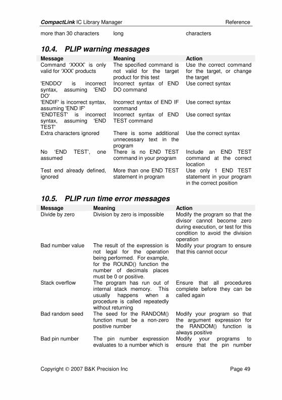
CompactLink IC Library Manager Reference
Copyright 2007 B&K Precision Inc Page 49
more than 30 characters long characters
10.4. PLIP warning messages Message Meaning Action Command ‘XXXX’ is only valid for ‘XXX’ products
The specified command is not valid for the target product for this test
Use the correct command for the target, or change the target
'ENDDO' is incorrect syntax, assuming 'END DO'
Incorrect syntax of END DO command
Use correct syntax
'ENDIF' is incorrect syntax, assuming 'END IF'
Incorrect syntax of END IF command
Use correct syntax
'ENDTEST' is incorrect syntax, assuming 'END TEST'
Incorrect syntax of END TEST command
Use correct syntax
Extra characters ignored There is some additional unnecessary text in the program
Use the correct syntax
No ‘END TEST’, one assumed
There is no END TEST command in your program
Include an END TEST command at the correct location
Test end already defined, ignored
More than one END TEST statement in program
Use only 1 END TEST statement in your program in the correct position
10.5. PLIP run time error messages Message Meaning Action Divide by zero Division by zero is impossible Modify the program so that the
divisor cannot become zero during execution, or test for this condition to avoid the division operation
Bad number value The result of the expression is not legal for the operation being performed. For example, for the ROUND() function the number of decimals places must be 0 or positive.
Modify your program to ensure that this cannot occur
Stack overflow The program has run out of internal stack memory. This usually happens when a procedure is called repeatedly without returning
Ensure that all procedures complete before they can be called again
Bad random seed The seed for the RANDOM() function must be a non-zero positive number
Modify your program so that the argument expression for the RANDOM() function is always positive
Bad pin number The pin number expression evaluates to a number which is
Modify your programs to ensure that the pin number
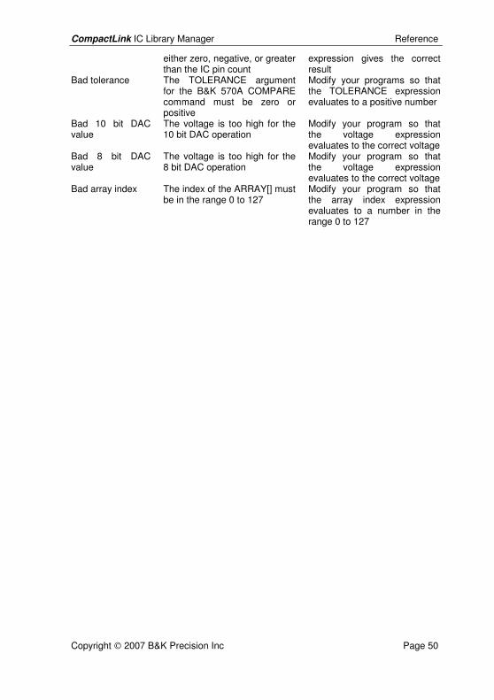
CompactLink IC Library Manager Reference
Copyright 2007 B&K Precision Inc Page 50
either zero, negative, or greater than the IC pin count
expression gives the correct result
Bad tolerance The TOLERANCE argument for the B&K 570A COMPARE command must be zero or positive
Modify your programs so that the TOLERANCE expression evaluates to a positive number
Bad 10 bit DAC value
The voltage is too high for the 10 bit DAC operation
Modify your program so that the voltage expression evaluates to the correct voltage
Bad 8 bit DAC value
The voltage is too high for the 8 bit DAC operation
Modify your program so that the voltage expression evaluates to the correct voltage
Bad array index The index of the ARRAY[] must be in the range 0 to 127
Modify your program so that the array index expression evaluates to a number in the range 0 to 127
CompactLink IC Library Manager Index
Copyright 2007 B&K Precision Inc Page 51
11. Index
A
Adding an IC · 7 Analog test programming · 25 Appendices · 40
B
Breakpoints · 18
C
Checklist · 4 CompactLink error/warning messages
· 41 CompactLink operation · 6 Compiler errors · 19 Compiling a programme · 14 Copying an IC · 7 Copyright · 2
D
Debugging · 17 Debugging window · 13 Deleting an IC · 10 Developing a functional test · 10 Digital test programming · 22 Disclaimers · 2 Documenting programmes · 15
E
Editing an IC · 7
Entering a programme · 14 Example of a 7400 digital IC test · 27 Exporting a device · 11
F
Fixing programme errors · 15 Fixing programme warnings · 15
G
Generating library files · 11 Getting started · 4
H
Hardware connection · 16 Help · 15
I
IC library data structure · 6 Installing CompactLink · 5 Introduction · 3 Introduction to PLIP · 12
L
Library parameter reference · 40 Logical errors · 19
M
Maintenance · 1
CompactLink IC Library Manager Index
Copyright 2007 B&K Precision Inc Page 52
P
PLIP command and function reference · 37
PLIP error messages · 44 PLIP run time error messages · 49 PLIP warning messages · 49 Precautions · 1 Printing a device · 11 Programming concepts · 22
R
Reviewing the IC library · 6 Run time errors · 19 Running CompactLink · 5
S
Specifying a functional test · 8
System requirements · 4
T
Test development window · 13 Troubleshooting and support · 39
V
Viewing an IC · 7
W
Writing test programmes · 12