bject oriented analysis - ucsb computer …cs.ucsb.edu/~mikec/cs48/project/processlarman.pdf · the...
TRANSCRIPT

Chapter 1
OBJECT-ORIENTED ANALYSIS AND DESIGN
The shift of focus (to patterns) will have a profound and enduring effect on the way we write programs.
—Ward Cunningham and Ralph Johnson
Objectives
• Compare and contrast analysis and design. • Define object-oriented analysis and design (OOA/D). • Illustrate a brief example.
1.1 Applying UML and Patterns in OOA/D
This is an introduction
What does it mean to have a good object design? This book is a tool to help devel-opers and students learn core skills in object-oriented analysis and design (OOA/D). These skills are essential for the creation of well-designed, robust, and maintainable software using object technologies and languages such as Java, C++, Smalltalk, and C#. The proverb "owning a hammer doesn't make one an architect" is especially true with respect to object technology. Knowing an object-oriented language (such as Java) is a necessary but insufficient first step to create object systems. Knowing how to "think in objects" is also critical.
This is an introduction to OOA/D while applying the Unified Modeling Lan-guage (UML), patterns, and the Unified Process. It is not meant as an advanced text; it emphasizes mastery of the fundamentals, such as how to assign respon-sibilities to objects, frequently used UML notation, and common design pat-
1 - OBJECT-ORIENTED ANALYSIS AND DESIGN
Applying UML
Applying patterns and assigning responsibilities
One case study
Use cases and requirements analysis
An example iterative process— the Unified Process
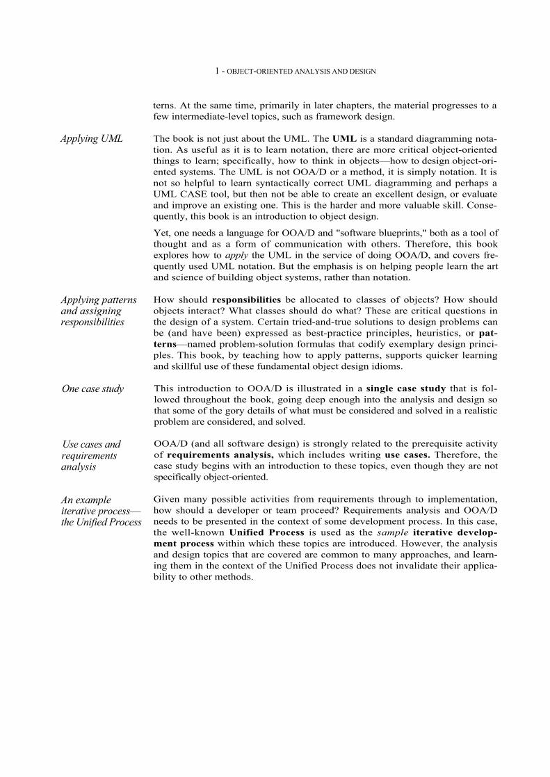
terns. At the same time, primarily in later chapters, the material progresses to a few intermediate-level topics, such as framework design.
The book is not just about the UML. The UML is a standard diagramming nota-tion. As useful as it is to learn notation, there are more critical object-oriented things to learn; specifically, how to think in objects—how to design object-ori-ented systems. The UML is not OOA/D or a method, it is simply notation. It is not so helpful to learn syntactically correct UML diagramming and perhaps a UML CASE tool, but then not be able to create an excellent design, or evaluate and improve an existing one. This is the harder and more valuable skill. Conse-quently, this book is an introduction to object design.
Yet, one needs a language for OOA/D and "software blueprints," both as a tool of thought and as a form of communication with others. Therefore, this book explores how to apply the UML in the service of doing OOA/D, and covers fre-quently used UML notation. But the emphasis is on helping people learn the art and science of building object systems, rather than notation.
How should responsibilities be allocated to classes of objects? How should objects interact? What classes should do what? These are critical questions in the design of a system. Certain tried-and-true solutions to design problems can be (and have been) expressed as best-practice principles, heuristics, or pat-terns—named problem-solution formulas that codify exemplary design princi-ples. This book, by teaching how to apply patterns, supports quicker learning and skillful use of these fundamental object design idioms.
This introduction to OOA/D is illustrated in a single case study that is fol-lowed throughout the book, going deep enough into the analysis and design so that some of the gory details of what must be considered and solved in a realistic problem are considered, and solved.
OOA/D (and all software design) is strongly related to the prerequisite activity of requirements analysis, which includes writing use cases. Therefore, the case study begins with an introduction to these topics, even though they are not specifically object-oriented.
Given many possible activities from requirements through to implementation, how should a developer or team proceed? Requirements analysis and OOA/D needs to be presented in the context of some development process. In this case, the well-known Unified Process is used as the sample iterative develop-ment process within which these topics are introduced. However, the analysis and design topics that are covered are common to many approaches, and learn-ing them in the context of the Unified Process does not invalidate their applica-bility to other methods.

APPLYING UML AND PATTERNS IN OOA/D
In conclusion, this book helps a student or developer: • Apply principles and patterns to create better object designs. • Follow a set of common activities in analysis and design, based on the
Unified Process as an example. • Create frequently used diagrams in the UML notation.
It illustrates this in the context of a single case study.
Topics and Skills
UML notation
Requirementsanalysis
Principles andguidelines
Patterns
Iterativedevelopment with
the UnifiedProcess
OOA/D
Figure 1.1 Topics and skills covered
Many Other Skills Are Important
Building software involves myriad skills and steps beyond requirements analy-sis, OOA/D, and object-oriented programming. For example, usability engineer-ing and user interface design are critical to success; so is database design. However, this introduction emphasizes OOA/D, and does not attempt to cover all topics in software development. It is one piece of a larger picture.
5

1 - OBJECT-ORIENTED ANALYSIS AND DESICN
1.2 Assigning Responsibilities
There are many possible activities and artifacts in introductory OOA/D, and a wealth of principles and guidelines. Suppose we must choose a single practical skill from all the topics discussed here—a "desert island" skill. What would it be?
A critical, fundamental ability in OOA/D is to skillfully assign responsibilities to software components.
Why? Because it is one activity that must be performed—either while drawing a UML diagram or programming—and it strongly influences the robustness, maintainability, and reusability of software components. Of course, there are other necessary skills in OOA/D, but responsibility assign-ment is emphasized in this introduction because it tends to be a challenging skill to master, and yet vitally important. On a real project, a developer might not have the opportunity to perform any other analysis or design activities—the "rush to code" development process. Yet even in this situation, assigning respon-sibilities is inevitable. Consequently, the design steps in this book emphasize principles of responsibil-ity assignment.
Nine fundamental principles in object design and responsibility assignment are presented and applied. They are organized in a learning aid called the GRASP patterns.
1.3 What Is Analysis and Design?
Analysis emphasizes an investigation of the problem and requirements, rather than a solution. For example, if a new computerized library information system is desired, how will it be used?
"Analysis" is a broad term, best qualified, as in requirements analysis (an inves-tigation of the requirements) or object analysis (an investigation of the domain objects). Design emphasizes a conceptual solution that fulfills the requirements, rather than its implementation. For example, a description of a database schema and software objects. Ultimately, designs can be implemented.
6

WHAT Is OBJECT-ORIENTED ANALYSIS AND DESIGN?
As with analysis, the term is best qualified, as in object design or database design. Analysis and design have been summarized in the phase do the right thing (analysis), and do the thing right (design).
1.4 What Is Object-Oriented Analysis and Design?
During object-oriented analysis, there is an emphasis on finding and describ-ing the objects—or concepts—in the problem domain. For example, in the case of the library information system, some of the concepts include Book, Library, and Patron. During object-oriented design, there is an emphasis on defining software objects and how they collaborate to fulfill the requirements. For example, in the library system, a Book software object may have a title attribute and a getChap-ter method (see Figure 1.2). Finally, during implementation or object-oriented programming, design objects are implemented, such as a Book class in Java.
Figure 1.2 Object-orientation emphasizes representation of objects.
1.5 An Example
Before diving into the details of requirements analysis and OOA/D, this section presents a birds-eye view of a few key steps and diagrams, using a simple example—a "dice game" in which a player rolls two die. If the total is seven, they win; otherwise, they lose.
7
Book
title
public class Book{private String title;
public Chapter getChapter(int) {...}}
domain concept visualization ofdomain concept
representation in anobject-orientedprogramming language

8 1 - OBJECT-ORIENTED ANALYSIS AND DESIGN
Define Use Cases
Requirements analysis may include a description of related domain processes; these can be written as use cases.
Use cases are not an object-oriented artifact—they are simply written stories. However, they are a popular tool in requirements analysis and are an important part of the Unified Process. For example, here is a brief version of the Play a Dice Game use case:
Play a Dice Game: A player picks up and rolls the dice. If the dice face value total seven, they win; otherwise, they lose.
Define a Domain Model
Object-oriented analysis is concerned with creating a description of the domain from the perspective of classification by objects. A decomposition of the domain involves an identification of the concepts, attributes, and associations that are considered noteworthy. The result can be expressed in a domain model, which is illustrated in a set of diagrams that show domain concepts or objects.
For example, a partial domain model is shown in Figure 1.3.
Figure 1.3 Partial domain model of the dice game.
Define domainmodel
Defineinteractiondiagrams
Define designclass diagramsDefine use cases
Define domainmodel
Defineinteractiondiagrams
Define designclass diagramsDefine use cases
Player
name
DiceGame
Die
faceValueRolls
Plays
Includes
2
2
1
1
1
1
AN EXAMPLE
This model illustrates the noteworthy concepts Player, Die, and DiceGame, with their associations and attributes.
Note that a domain model is not a description of software objects; it is a visual-ization of concepts in the real-world domain.
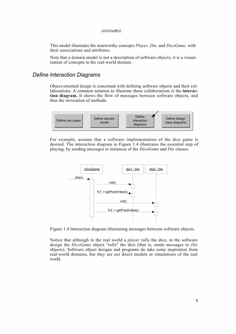
Define Interaction Diagrams
Object-oriented design is concerned with defining software objects and their col-laborations. A common notation to illustrate these collaborations is the interac-tion diagram. It shows the flow of messages between software objects, and thus the invocation of methods.
For example, assume that a software implementation of the dice game is desired. The interaction diagram in Figure 1.4 illustrates the essential step of playing, by sending messages to instances of the DiceGame and Die classes.
Figure 1.4 Interaction diagram illustrating messages between software objects.
Notice that although in the real world a player rolls the dice, in the software design the DiceGame object "rolls" the dice (that is, sends messages to Die objects). Software object designs and programs do take some inspiration from real-world domains, but they are not direct models or simulations of the real world.
9
Define domainmodel
Defineinteractiondiagrams
Define designclass diagramsDefine use cases
:DiceGame
play()
die1 : Die
fv1 := getFaceValue()
die2 : Die
roll()
roll()
fv2 := getFaceValue()

1 - OBJECT-ORIENTED ANALYSIS AND DESIGN
Define Design Class Diagrams
In addition to a dynamic view of collaborating objects shown in interaction dia-grams, it is useful to create a static view of the class definitions with a design class diagram. This illustrates the attributes and methods of the classes.
For example, in the dice game, an inspection of the interaction diagram leads to the partial design class diagram shown in Figure 1.5. Since a play message is sent to a DiceGame object, the DiceGame class requires a play method, while class Die requires a roll and getFaceValue method.
In contrast to the domain model, this diagram does not illustrate real-world con-cepts; rather, it shows software classes.
Figure 1.5 Partial design class diagram.
Summary
The dice game is a simple problem, presented to focus on a few steps and arti-facts in analysis and design. To keep the introduction simple, not all the illus-trated UML notation was explained. Future chapters explore analysis and design and these artifacts in closer detail.
1.6 The UML
To quote:
The Unified Modeling Language (UML) is a language for speci-fying, visualizing, constructing, and documenting the artifacts of software systems, as well as for business modeling and other non-software systems [OMG01].
The UML has emerged as the de facto and de jure standard diagramming nota-tion for object-oriented modeling. It started as an effort by Grady Booch and Jim Rumbaugh in 1994 to combine the diagramming notations from their two popu-
10
Define domainmodel
Defineinteractiondiagrams
Define designclass diagramsDefine use cases
2
Die
faceValue : int
getFaceValue() : introll()
DiceGame
die1 : Diedie2 : Die
play()
1

FURTHER READINGS
lar methods—the Booch and OMT (Object Modeling Technique) methods. They were later joined by Ivar Jacobson, the creator of the Objectory method, and as a group came to be known as the three amigos. Many others contributed to the UML, perhaps most notably Cris Kobryn, a leader in its ongoing refinement. The UML was adopted in 1997 as a standard by the OMG (Object Management Group, an industry standards body), and has continued to be refined in new OMG UML versions. This book does not cover every minute aspect of the UML, which is a large body of notation (some say, too large1). It focuses on diagrams which are frequently used, the most commonly used features within those diagrams, and core nota-tion that is unlikely to change in future versions of the UML.
Why Won't We See Much UML fora Few Chapters?
This is not just a UML notation book, but one that explores the larger picture of applying the UML, patterns, and an iterative process in the context of software development. The UML is primarily applied during OOA/D, which is normally preceded by requirements analysis. Therefore, the initial chapters present an introduction to the important topics of use cases and requirements analysis, which are then followed by chapters on OOA/D and more UML details.
1.7 Further Readings
A very readable and popular summary of essential UML notation is UML Dis-tilled, by Martin Fowler. A succinct and popular introduction to the Unified Process (and its refinement in the Rational Unified Process) is The Rational Unified Process—An Introduc-tion by Philippe Kruchten. For a detailed discussion of UML (version 1.3) notation, The Unified Modeling Language Reference Manual and The Unified Modeling Language User Guide, by Booch, Jacobson, and Rumbaugh are worthwhile. Note that these texts were not meant for learning how to do object modeling or OOA/D—they are UML dia-gram notation references. For a description of the current version of the UML, the on-line OMG Unified Modeling Language Specification at www.omg.org is necessary. UML revision work and soon-to-be released versions can be found at www.celigent.com/uml. There are many books on software patterns, but the seminal classic is Design Patterns, by Gamma, Helm, Johnson, and Vlissides. It is truly required reading
1. The UML 2.0 effort includes exploration of the goal of simplifying and reducing the notation. This book presents high-use UML likely to survive future simplification.
11

12
1 - OBJECT-ORIENTED ANALYSIS AND DESIGN
for those studying object design. However, it is not an introductory text and is best read after developing comfort with the fundamentals of object design and programming.

Chapter 2
ITERATIVE DEVELOPMENT AND THE UNIFIED PROCESS
People are more important than any process.
Good people with a good process will outperform good people with no process every time.
—Grady Booch
Objectives
• Provide motivation for the content and order of subsequent chapters. • Define an iterative and adaptive process. • Define fundamental concepts in the Unified Process.
Introduction
Iterative development is a skillful approach to software development, and lies at the heart of how OOA/D is presented in this book. The Unified Process is an example iterative process for projects using OOA/D, and it shapes the book's presentation. Consequently, it is useful to read this chapter so that these core concepts and their influence on the book's structure are clear. This chapter summarizes a few key ideas; please see Chapter 37 for further dis-cussion of the UP and iterative process practices. Informally, a software development process describes an approach to build-ing, deploying, and possibly maintaining software. The Unified Process [JBR99] has emerged as a popular software development process for building object-oriented systems. In particular, the Rational Unified Process or RUP
13

2 - ITERATIVE DEVELOPMENT AND THE UNIFIED PROCESS
[KruchtenOO], a detailed refinement of the Unified Process, has been widely adopted.
The Unified Process (UP) combines commonly accepted best practices, such as an iterative lifecycle and risk-driven development, into a cohesive and well-doc-umented description. Consequently, it is used in this book as the example pro-cess within which to introduce OOA/D.
This book starts with an introduction to the UP for two reasons:
1. The UP is an iterative process. Iterative development is a valuable practice that influences how this book introduces OOA/D, and how it is best prac ticed.
2. UP practices provide an example structure to talk about how to do—and how to learn—OOA/D.
This text presents an introduction to the UP, not complete coverage. It emphasizes common ideas and artifacts related to an introduction to OOA/D and requirements analysis.
What If I Don't Care About the UP?
The UP is used as an example process within which to explore requirements analysis and OOA/D, since it is necessary to introduce the subject in the context of some process, and the UP (or the RUP refinement) is relatively widely used. Also, the UP presents common activities and best practices. Nevertheless, the central ideas of this book—such as use cases and design patterns—are indepen-dent of any particular process, and apply to many.
2.1 The Most Important UP Idea: Iterative Development
The UP promotes several best practices, but one stands above the others: itera-tive development. In this approach, development is organized into a series of short, fixed-length (for example, four week) mini-projects called iterations; the outcome of each is a tested, integrated, and executable system. Each iteration includes its own requirements analysis, design, implementation, and testing activities.
The iterative lifecycle is based on the successive enlargement and refinement of a system through multiple iterations, with cyclic feedback and adaptation as core drivers to converge upon a suitable system. The system grows incremen-tally over time, iteration by iteration, and thus this approach is also known as iterative and incremental development (see Figure 2.1).
14

Figure 2.1 Iterative and incremental development.
Example As an example (not a recipe), in a two-week iteration half-way through a project, perhaps Monday is spent primarily on distributing and clarifying the tasks and requirements of the iteration, while one person reverse-engineers the last iteration's code into UML diagrams (via a CASE tool), and prints and displays noteworthy diagrams. Tuesday is spent at whiteboards doing pair design work drawing rough UML diagrams captured on digital cameras, and writing some pseudocode and design notes. The remaining eight days are spent on implementation, testing (unit, acceptance, usability, ...), further design, integration, daily builds, system testing, and stabilization of the par-tial system. Other activities include demonstrations and evaluations with stakeholders, and planning for the next iteration.
Notice in this example that there is neither a rush to code, nor a long drawn-out design step that attempts to perfect all details of the design before program-ming. A "little" forethought regarding the design with visual modeling using rough and fast UML drawings is done; perhaps a half or full day by developers doing design work in pairs. The result of each iteration is an executable but incomplete system; it is not ready to deliver into production. The system may not be eligible for production deployment until after many iterations; for example, 10 or 15 iterations.
15
THE MOST IMPORTANT UP IDEA: ITERATIVE DEVELOPMENT
Early iterative process ideas were known as spiral development and evolution-ary development [Boehm.88, Gilb88].
Requirements
Design
Implementation &Test & Integration
& More Design
Final Integration& System Test
Requirements
Design
4 weeks (for example)The system growsincrementally.
Feedback fromiteration N leads torefinement andadaptation of therequirements anddesign in iterationN+1.
Iterations are fixed inlength, or timeboxed.
TimeImplementation &Test & Integration
& More Design
Final Integration& System Test

16
2 - ITERATIVE DEVELOPMENT AND THE UNIFIED PROCESS
The output of an iteration is not an experimental or throw-away prototype, and iterative development is not prototyping. Rather, the output is a production-grade subset of the final system. Although, in general, each iteration tackles new requirements and incremen-tally extends the system, an iteration may occasionally revisit existing software and improve it; for example, one iteration may focus on improving the perfor-mance of a subsystem, rather than extending it with new features.
Embracing Change: Feedback and Adaptation
The subtitle of one book that discusses iterative development is Embrace Change [BeckOO]. This phrase is evocative of a key attitude of iterative develop-ment: Rather than fighting the inevitable change that occurs in software devel-opment by trying (usually unsuccessfully) to fully and correctly specify, freeze, and "sign off" on a frozen requirement set and design before implementation, iterative development is based on an attitude of embracing change and adapta-tion as unavoidable and indeed essential drivers.
This is not to say that iterative development and the UP encourages an uncon-trolled and reactive "feature creep"-driven process. Subsequent chapters explore how the UP balances the need—on the one hand—to agree upon and stabilize a set of requirements, with—on the other hand—the reality of changing require-ments, as stakeholders clarify their vision or the marketplace changes.
Each iteration involves choosing a small subset of the requirements, and quickly designing, implementing, and testing. In early iterations the choice of require-ments and design may not be exactly what is ultimately desired. But the act of swiftly taking a small step, before all requirements are finalized, or the entire design is speculatively defined, leads to rapid feedback—feedback from the users, developers, and tests (such as load and usability tests).
This early feedback is worth its weight in gold; rather than speculating on the correct requirements or design, the feedback from realistic building and testing something provides crucial practical insight and an opportunity to modify or adapt understanding of the requirements or design. End-users have a chance to quickly see a partial system and say, "Yes, that's what I asked for, but now that I try it, what I really want is something slightly different."1 This "yes...but" pro-cess is not a sign of failure; rather, early and frequent structured cycles of "yes...buts" are a skillful way to make progress and discover what is of real value to the stakeholders. Yet, as mentioned, this is not an endorsement of chaotic and reactive development in which developers continually change direction—a mid-dle way is possible.
In addition to requirements clarification, activities such as load testing will prove if the partial design and implementation are on the right path, or if in the
1. Or more likely, "You didn't understand what I wanted!"

THE MOST IMPORTANT UP IDEA: ITERATIVE DEVELOPMENT
next iteration, a change in the core architecture is required. Better to resolve and prove the risky and critical design decisions early rather than late—and iterative development provides the mechanism for this.
Consequently, work proceeds through a series of structured build-feedback-adapt cycles. Not surprisingly, in early iterations the deviation from the "true path" of the system (in terms of its final requirements and design) will be larger than in later iterations. Over time, the system converges towards this path, as illustrated in Figure 2.2.
Figure 2.2 Iterative feedback and adaptation leads towards the desired system. The requirements and design instability lowers over time.
Benefits of Iterative Development
Benefits of iterative development include:
• early rather than late mitigation of high risks (technical, requirements, objectives, usability, and so forth)
• early visible progress
• early feedback, user engagement, and adaptation, leading to a refined sys tem that more closely meets the real needs of the stakeholders
• managed complexity; the team is not overwhelmed by "analysis paralysis" or very long and complex steps
• the learning within an iteration can be methodically used to improve the development process itself, iteration by iteration
Early iterations are farther from the "truepath" of the system. Via feedback andadaptation, the system converges towardsthe most appropriate requirements anddesign.
In late iterations, a significant change inrequirements is rare, but can occur. Suchlate changes may give an organization acompetitive business advantage.
one iteration of design,implement, integrate, and test

2 - ITERATIVE DEVELOPMENT AND THE UNIFIED PROCESS
Iteration Length and Timeboxing
The UP (and experienced iterative developers) recommends an iteration length between two and six weeks. Small steps, rapid feedback, and adaptation are central ideas in iterative development; long iterations subvert the core motiva-tion for iterative development and increase project risk. Much less than two weeks, and it is difficult to complete sufficient work to get meaningful through-put and feedback; much more than six or eight weeks, and the complexity becomes rather overwhelming, and feedback is delayed. A very long iteration misses the point of iterative development. Short is good.
A key idea is that iterations are timeboxed, or fixed in length. For example, if the next iteration is chosen to be four weeks long, then the partial system should be integrated, tested, and stabilized by the scheduled date—date slippage is dis-couraged. If it seems that it will be difficult to meet the deadline, the recom-mended response is to remove tasks or requirements from the iteration, and include them in a future iteration, rather than slip the completion date. Chapter 37 summarizes reasons for timeboxing.
Massive teams (for example, several hundred developers) may require longer than six-week iterations to compensate for the overhead of coordination and communication; but no more than three to six months is recommended. For example, the successful replacement in the 1990s of the Canadian air traffic control system was developed with an iterative lifecycle and other UP practices. It involved 150 programmers and was organized into six-month iterations.2 But note that even in the case of an overall six-month project iteration, a subsystem team of 10 or 20 developers can break down their work into a series of six one-month iterations.
A six-month iteration is the exception for massive teams, not the rule. To reiter-ate, the UP recommends that normally an iteration should be between two and six weeks in duration.
2.2 Additional UP Best Practices and Concepts
The central idea to appreciate and practice in the UP is short timeboxed itera-tive, adaptive development. Another implicit, but core, UP idea is the use of object technologies, including OOA/D and object-oriented programming.
2. Philippe Kruchten, who also led the development of the RUP, served as chief architect for the project.
18

THE UP PHASES AND SCHEDULE-ORIENTED TERMS
Some additional best practices and key concepts in the UP include: • tackle high-risk and high-value issues in early iterations • continuously engage users for evaluation, feedback, and requirements • build a cohesive, core architecture in early iterations • continuously verify quality; test early, often, and realistically • apply use cases • model software visually (with the UML) • carefully manage requirements • practice change request and configuration management See Chapter 37 for a more detailed description of these practices.
2.3 The UP Phases and Schedule-Oriented Terms
A UP project organizes the work and iterations across four major phases: 1. Inception— approximate vision, business case, scope, vague estimates. 2. Elaboration—refined vision, iterative implementation of the core architec
ture, resolution of high risks, identification of most requirements and scope, more realistic estimates.
3. Construction—iterative implementation of the remaining lower risk and easier elements, and preparation for deployment.
4. Transition—beta tests, deployment. These phases are more fully defined in subsequent chapters. This is not the old "waterfall" or sequential lifecycle of first defining all the requirements, and then doing all or most of the design. Inception is not a requirements phase; rather, it is a kind of feasibility phase, where just enough investigation is done to support a decision to continue or stop. Similarly, elaboration is not the requirements or design phase; rather, it is a phase where the core architecture is iteratively implemented, and high risk issues are mitigated. Figure 2.3 illustrates common schedule-oriented terms in the UP. Notice that one development cycle (which ends in the release of a system into production) is composed of many iterations.
19

Figure 2.3 Schedule-oriented terms in the UP.
2.4 The UP Disciplines (was Workflows)
The UP describes work activities, such as writing a use case, within disciplines (originally called workflows).3 Informally, a discipline is a set of activities (and related artifacts) in one subject area, such as the activities within requirements analysis. In the UP, an artifact is the general term for any work product: code, Web graphics, database schema, text documents, diagrams, models, and so on. There are several disciplines in the UP; this book focuses on some artifacts in the following three:
• Business Modeling—When developing a single application, this includes domain object modeling. When engaged in large-scale business analysis or business process reengineering, this includes dynamic modeling of the busi ness processes across the entire enterprise.
• Requirements—Requirements analysis for an application, such as writing use cases and identifying non-functional requirements.
• Design—All aspects of design, including the overall architecture, objects, databases, networking, and the like.
3. In 2001, the old UP term "workflow" was replaced by the new term "discipline" in order to harmonize with an international standardization effort called the OMG SPEM; because of its prior meaning in the UP, many continue to use the term work-flow to mean discipline, although this is not strictly correct. The term "workflow" took on a new but slightly different meaning within the UP: On a particular project, it is a particular sequence of activities (perhaps across disciplines)—a flow of work.
20
2 - ITERATIVE DEVELOPMENT AND THE UNIFIED PROCESS
inc. elaboration construction transition
iteration phase
development cycle
release
A stable executablesubset of the finalproduct. The end ofeach iteration is aminor release.
increment
The difference(delta) between thereleases of 2subsequentiterations.
final productionrelease
At this point, thesystem is releasedfor production use.
milestone
An iteration end-point when somesignificant decisionor evaluationoccurs.

Figure 2.4 UP disciplines.4
In the UP, Implementation means programming and building the system, not deployment. The Environment discipline refers to establishing the tools and customizing the process for the project—that is, setting up the tool and process environment.
Disciplines and Phases
As illustrated in Figure 2.4, during one iteration work goes on in most or all dis-ciplines. However, the relative effort across these disciplines changes over time. Early iterations naturally tend to apply greater relative emphasis to require-ments and design, and later ones less so, as the requirements and core design stabilize through a process of feedback and adaptation. Relating this to the UP phases (inception, elaboration, ...), Figure 2.5 illustrates the changing relative effort with respect to the phases; please note these are suggestive, not literal. In elaboration, for example, the iterations tend to have a
4. Diagram adapted from the RUP product.
THE UP DISCIPLINES (WAS WORKFLOWS)
A longer list of UP disciplines is shown in Figure 2.4.
Iterations
SampleUP Disciplines
Business Modeling
Requirements
Design
Implementation
Test
Deployment
Configuration & ChangeManagement
Project Management
Environment
Focusof thisbook
Note thatalthough aniteration includeswork in mostdisciplines, therelative effort andemphasis changeover time.
This example issuggestive, notliteral.
A four-week iteration (for example).A mini-project that includes work in mostdisciplines, ending in a stable executable.

22
2 - ITERATIVE DEVELOPMENT AND THE UNIFIED PROCESS
relatively high level of requirements and design work, although definitely some implementation as well. During construction, the emphasis is heavier on imple-mentation and lighter on requirements analysis.
Book Structure and UP Phases and Disciplines
With respect to the phases and disciplines, what is the focus of the case study? Answer:
The case study emphasizes the inception and elaboration phase. It focuses on some artifacts in the Business Modeling, Requirements, and Design disci-plines, as this is where requirements analysis, OOA/D, patterns, and the UML are primarily applied.
The earlier chapters introduce activities in inception; later chapters explore sev-eral iterations in elaboration. The following list and Figure 2.6 describe the organization with respect to the UP phases. 1. The inception phase chapters introduce the basics of requirements analysis. 2. Iteration 1 introduces fundamental OOA/D and how to assign responsibili
ties to objects. 3. Iteration 2 focuses on object design, especially on introducing some high-use
"design patterns." 4. Iteration 3 introduces a variety of subjects, such as architectural analysis
and framework design.
Figure 2.5 Disciplines and phases
SampleUP Disciplines
BusinessModeling
Requirements
Design
Implementation
...
The relative effort indisciplines shiftsacross the phases.
This example issuggestive, not literal.
incep-tion elaboration construction transi-
tion
...

Figure 2.6 Book organization is related to the UP phases and iterations.
2.5 Process Customization and the Development Case
Optional Artifacts
Some UP practices and principles are invariant, such as iterative and risk-driven development, and continuous verification of quality. However, a key insight into the UP is that all activities and artifacts (models, diagrams, documents, ...) are optional—well, maybe not the code! The set of pos-sible artifacts described in the UP should be viewed like a set of medicines in a pharmacy. Just as one does not indiscriminately take many medicines, but matches the choice to the ailment, likewise on a UP project, a team should select a small subset of artifacts that address its particular problems and needs. In general, focus on a small set of artifacts that demonstrate high practical value.
The Development Case
The choice of UP artifacts for a project may be written up in a short document called the Development Case (an artifact in the Environment discipline). For example, Table 2.1 could be the Development Case describing the artifacts for the "NextGen Project" case study explored in this book. Subsequent chapters describe the creation of some of these artifacts, including the Domain Model, Use-Case Model, and Design Model. The example artifacts presented in this case study are by no means sufficient for, or suitable for, all projects. For example, a machine control system may ben-efit from doing many state diagrams. A Web-based e-commerce system may require a focus on user interface prototypes. A "green-field" new development
23
PROCESS CUSTOMIZATION AND THE DEVELOPMENT CASE
Overview InceptionElaboratio
nIteration 1
Elaboration
Iteration 2
Elaboration
Iteration 3
Object-OrientedAnalysis
Object-OrientedDesign
TranslatingDesigns to Code
The Book
Topics such as OO analysis and OOdesign are incrementally introduced initeration 1, 2, and 3.
SpecialTopics

2 - ITERATIVE DEVELOPMENT AND THE UNIFIED PROCESS
project has very different design artifact needs than a systems integration project.
Discipline Artifact Iteration-*
Incep.11
Elab.El. .En
Const. CL.Cn
Trans. T1..T2
Business Modeling Domain Model s Use-Case Model s r Vision s r Supplementary Specification s r
Requirements
Glossary s r Design Model s r SW Architecture Document s
Design
Data Model s r Implementation Implementation Model s r r Project Management SW Development Plan s r r r Testing Test Model s r Environment Development Case s r
Table 2.1 Sample Development Case of UP artifacts, s - start; r - refine
2.6 The Agile UP
Methodologists speak of processes as heavy vs. light, and predictive vs. adaptive. A heavy process is a pejorative term meant to suggest one with the following qualities [FowlerOO]: • many artifacts created in a bureaucratic atmosphere
• rigidity and control
• elaborate, long-term, detailed planning
• predictive rather than adaptive
A predictive process is one that attempts to plan and predict the activities and resource (people) allocations in detail over a relatively long time span, such as the majority of a project. Predictive processes usually have a "waterfall" or sequential lifecycle—first, defining all the requirements; second, defining a detailed design; and third, implementing. In contrast, an adaptive process is one that accepts change as an inevitable driver and encourages flexible adapta-tion; they usually have an iterative lifecycle. An agile process implies a light and adaptive process, nimble in response to changing needs.
The UP was not meant by its authors to be either heavy or predictive, although its large optional set of activities and artifacts have understandably led to that
24

THE SEQUENTIAL "WATERFALL" LIFECYCLE
impression in some. Rather, it was meant to be adopted and applied in the spirit of an agile process—agile UP. Some examples of how this applies: • Prefer a small set of UP activities and artifacts. Some projects will benefit
from more than others, but, in general, keep it simple. • Since the UP is iterative, requirements and designs are not completed
before implementation. They adaptively emerge through a series of itera tions, based on feedback.
• There isn't a detailed plan for the entire project. There is a high level plan (called the Phase Plan) that estimates the project end date and other major milestones, but it does not detail the fine-grained steps to those milestones. A detailed plan (called the Iteration Plan) only plans with greater detail one iteration in advance. Detailed planning is done adaptively from itera tion to iteration. Please see Chapter 36 for some comments on planning iter ative projects, and the justification for this approach.
The case study emphasizes a relatively small number of artifacts, and iterative development, in the spirit of an agile UP.
2.7 The Sequential "Waterfall" Lifecycle
In contrast to the iterative lifecycle of the UP, an old alternative was the sequen-tial, linear, or "waterfall" lifecycle [RoyceTO]. In common usage, it defined steps similar to the following: 1. Clarify, record, and commit to a set of complete and frozen requirements. 2. Design a system based on these requirements. 3. Implement, based on the design. A two year study reported in the MIT Sloan Management Review of successful software projects identified four common factors for success; iterative develop-ment, rather than a waterfall process, was first on the list [MacCormackO!!.•'' A brief description of its problems, and how they are mitigated by iterative development, is presented in Chapter 37.
5. The others were: 2) at least daily incorporation of new code into a complete system build, and rapid feedback on design changes (via testing); 3) a team experienced in shipping multiple products; and 4) an early focus on building and proving a cohesive architecture. Three of these four factors are explicit practices in the UP.
25

2 - ITERATIVE DEVELOPMENT AND THE UNIFIED PROCESS
2.8 You Know You Didn't Understand the UP When...
Here are some signs that indicate when you have not understood what it means to adopt the UP and iterative development in the agile spirit intended by the UP.
• You think that inception = requirements, elaboration = design, and con struction = implementation (that is, superimposing a waterfall lifecycle on to the UP).
• You think that the purpose of elaboration is to fully and carefully define models, which are translated into code during construction.
• You try to define most of the requirements before starting design or imple mentation.
• You try to define most of the design before starting implementation; you try to fully define and commit to an architecture before iterative programming and testing.
• A "long time" is spent doing requirements or design work before program ming starts.
• You believe that a suitable iteration length is four months long, rather than four weeks long (excluding projects with hundreds of developers).
• You think UML diagramming and design activities are a time to fully and accurately define designs and models in great detail, and of programming as a simple mechanical translation of these into code.
• You think that adopting the UP means to do many of the possible activities and create many documents, and thinks of or experiences the UP as a for mal, fussy process with many steps to be followed.
• You try to plan a project in detail from start to finish; you try to specula- tively predict all the iterations, and what should happen in each one.
• You want believable plans and estimates for projects before the elaboration phase is finished.
2.9 Further Readings
A very readable introduction to the UP and its refinement in the RUP is The Rational Unified Process—An Introduction by Philippe Kruchten, the lead architect of the RUP.
A description of the original UP can be found in The Unified Software Develop-ment Process by Jacobson, Booch, and Rumbaugh. It is worth study, but Kruchten's introduction is recommended first, as it is smaller and more suc-cinct, and the RUP updates and refines the original UP.
26

FURTHER READINGS
Rational Software sells the online Web-based RUP documentation product, which provides comprehensive reading on RUP artifacts and activities, and tem-plates for most artifacts. See Chapter 37 for a brief discussion. An organization can run a UP project just using mentors and books as learning resources, but some find the RUP product a useful learning and process aid. UP activities are also loosely described in a series of books edited by Ambler and Constantine (for example, The Unified Process: Elaboration Phase [AmblerOO]). These books contain reprints of articles published over the years in Software Development magazine, categorized into their respective phase and activity in terms of a UP taxonomy. Note that the articles were not originally written for the UP, although they definitely contain useful advice. Also note one slight error in the series: They describe the UP elaboration phase as a phase in which throw-away prototypes are created, thus reducing the need for attention to care in the programming or design. This is not accurate; production-quality (albeit partial) designs and code are created during elaboration. Ambler recognizes the inaccuracy and may correct it in a subsequent edition.6
For other agile methods, the Extreme Programming (XP) series of books IBeckOO, BFOO, JAHOO] are recommended, such as Extreme Programming Explained. Some XP practices are mentioned in later chapters. Most XP prac-tices (such as test-first programming and iterative development) are compati-ble—or identical—with UP practices, and I encourage their adoption on a UP project. Note that the XP did not (nor did it claim too) invent short timeboxed iterative and adaptive development, which has been a practice in the UP and other iterative methods for years. Two noteworthy differences—this is not a complete list—between the UP and XP are: 1) The UP recommends incremen-tally writing use cases and a non-functional requirements document (XP does not); and, 2) The UP recommends more visual design diagramming (such as a half-day or day) near the start of an iteration, before major programming. The XP leaders recommend very little, such as 30 minutes.
Highsmith provides justification for the value of adaptive development in Adap-tive Software Development [HighsmithOO].
6. Ambler, private communication.
27