bipolar transfection system
TRANSCRIPT

AgilePulse™ PLUSBipolar
Transfection SystemUSER’S MANUAL
Publication 5423-030 Rev 1.0

AgilePulse PLUS Bipolar Transfection SystemPublication 5423-030 Rev 1.0 • www.btxonline.com
Thank you for investing in an AgilePluse PLUS system.
Since its founding in 1983, the main focus of BTX has been in the area of applying controlled electric fields for genetic engineering applications. Because of this, we quickly established a reputation as the technological leader in the fields of electroporation and electrofusion. Our systems have been installed in many prestigious institutes around the globe where they are used successfully for high efficiency transfection, transformation and cell fusion applications. We offer a variety of waveforms, electrodes and chamber options to provide you with the best tools to achieve your goals.
We are vested in your success. To that end, the BTX technical support team constantly tracks published literature for any reference to electroporation and electrofusion. We extract the pertinent experimental conditions and yields from these papers to help us in our efforts to help you. In addition to tracking publications, we are available to you for support at any time for advice in experimental design, product recommendations, troubleshooting, and any other relevant technical advice.
We thank you again for your investment and we look forward to assisting you in any way we can.
Finally, please read this manual carefully before attempting to operate the electroporation system. If you have any questions about the unit or about particular applications, please contact us:
BTX 84 October Hill Road Holliston, MA 01746 USA
Toll Free: 800-272-2775 International Callers: 508-893-8999 Fax: 508-429-5732 Web: www.btxonline.com Email: [email protected]
For any customers outside the US or Canada, please call your local BTX dealer or call us directly.
A Message from BTX

1AgilePulse PLUS Bipolar Transfection System
Publication 5423-030 Rev 1.0 • www.btxonline.com
SUBJECT PAGE #
Warranty Information 3
Safety Information 4
AgilePulse™ PLUS Product Overview 5
AgilePulse PLUS System Components and Setup 6–9
System Components 6–8
AgilePulse PLUS Waveform Generator 6
Safety Stand for Flatpacks and Cuvettes 7
Cytoporation® Medium 7
High Voltage Output Cable for 4-mm Banana Cable Accessories 8
Large Volume Chamber and Stand 8
Setting Up the System 9
Initial System Test 9
AgilePulse PLUS System Operation 10–18
Waveform Generator 10–18
Login Screen: User Identification Input 10
Welcome Screen: Sample Identification Input 11
Pulse Delivery Screen: Functions and Operation 11
User Account Maintenance 12
Protocol Setup 13
Log File Maintenance 14
Electroporation Protocol Delivery Logs 15
Text Log 16
CSV Data 17
Delivery Completion Return Codes 18
AgilePulse PLUS In Vitro Electroporation Protocol 19–20
Transfection Process 19
Preparing Cell Suspensions for Large Volume Transfection 19
Filling Large Volume Chambers 19
Electroporation 20
Cell Handling After Electroporation 20
AgilePulse PLUS in Vivo Electroporation Protocol 21
AgilePulse Set Up 21
Injection 21
Electroporation 21
AgilePulse PLUS Tutorial 22–27
Applications 22
DNA/RNA Delivery Into Cells Using Electroporation 22
General Electroporation Discussion 22
PulseAgile® Electroporation 23–24
Induction of a State of Permeability 24
Movement of DNA or RNA Across Cell Membranes 24
Minimizing Heat Production with Waveform 24
Putting the AgilePulse PLUS Concepts Together 24
Importance of Medium Conductivity in Electroporation 25–26
Table of Contents

2AgilePulse PLUS Bipolar Transfection System
Publication 5423-030 Rev 1.0 • www.btxonline.com
Table of Contents
LIST OF FIGURES PAGE #
Figure 1: Waveform Generator 5
Figure 2: Waveform Generator Front Panel 6
Figure 3: Safety Stand for Flatpack 7
Figure 4: Cytoporation Medium 7
Figure 5: High Voltage Output Cable, for 4 mm Banana Cable Accessories 8
Figure 6: Large Volume Chamber and Stand 8
Figure 7: Start Up Screen Display 9
Figure 8: Login Screen 10
Figure 9: Welcome Screen 11
Figure 10: Pulse Delivery Screen — Pre-Pulse 11
Figure 11: Pulse Delivery Screen — Post-Pulse 12
Figure 12: User Account Screen 12
Figure 13: Protocol Screen 13
Figure 14: Log File Maintenance Screen 14
Figure 15: Text Log Screen 16
Figure 16: Sample Amplitude Analysis 17
Figure 17: Electroporation 22
Figure 18: Transmembrane Voltage 23
Figure 19: Fuse Replacement 29
SUBJECT PAGE #
Cytoporation® Medium Properties 27
Conductivity 27
Media Formulas 27
Other Important Cytoporation® Medium Properties 27
Specifications 28
Maintenance 29
Fuse Replacement 29
Electrode Care and Cleaning 29
Ordering Information 30
References 31

3AgilePulse PLUS Bipolar Transfection System
Publication 5423-030 Rev 1.0 • www.btxonline.com
Warranty Information
RESEARCH ONLY BTX
84 October Hill Rd Holliston, MA 01746, USA
Phone: 1-508-893-8999 Fax: 1-800-429-5732 Web: www.btxonline.com
WarrantyBTX warranties AgilePulse™ systems for a period of two years from the date of purchase. At its option, BTX will repair or replace the product if it is found to be defective as to workmanship or materials. This warranty does not extend to any device which has been (a) subjected to misuse, neglect, accident or abuse, (b) repaired or altered by anyone other than BTX without BTX express and prior approval, (c) used in violation of instructions furnished by BTX. This warranty extends only to the original customer purchaser. IN NO EVENT SHALL BTX BE LIABLE FOR INCIDENTAL OR CONSEQUENTIAL DAMAGES. Some states do not allow exclusion or limitation of incidental or consequential damages so the above limitation or exclusion may not apply to you. THERE ARE NO IMPLIED WARRANTIES OF MERCHANTABILITY, OR FITNESS FOR A PARTICULAR USE, OR OF ANY OTHER NATURE. Some states do not allow this limitation on an implied warranty, so the above limitation may not apply to you. Without limiting the generality of the foregoing, BTX shall not be liable for any claims of any kind whatsoever, as to the equipment delivered or for non-delivery of equipment, and whether or not based on negligence. Warranty is void if the BTX AgilePulse system is changed in any way from its original factory design or if repairs are attempted without written authorization by BTX. Warranty is void if parts, connections or electrodes not manufactured by BTX are used with the BTX AgilePulse instrument. If a defect arises within the warranty period, promptly contact BTX, 84 October Hill Road, Building 7, Holliston, Massachusetts, USA 01746-1388 using our toll free number 800-272-2775 (US Only) or 508-547-6766 (E-mail: [email protected]). Goods will not be accepted for return unless an RMA (Returned Materials Authorization) number has been issued by our returns/repairs department. The customer is responsible for shipping charges. Please allow a reasonable period of time for completion of repairs, replacement and return. If the unit is replaced, the replacement unit is covered only for the remainder of the original warranty period dating from the purchase of the original device. This warranty gives you specific rights, and you may also have other rights, which vary from state to state.
Out of Warranty ServiceProceed exactly as for Warranty Service above. If our service department can assist you by phone or other correspondence, we will be glad to help at no charge.
Repair service will be billed on the basis of labor and materials. A complete statement of time spent and materials used will be supplied. Shipment to BTX should be prepaid. Your bill will include return shipment freight charges.
Disassembly by the user is prohibited. Service should only be carried out by experienced BTX technicians.
Repair Facilities and PartsBTX stocks replacement and repair parts. When ordering, please describe parts as completely as possible, preferably using our part numbers. If practical, enclose a sample photo or drawing.
Caution NoticeThe BTX AgilePulse systems are intended for laboratory use only and can be used in research and development applications. These systems have been designed to meet the standards for electromagnetic compatibility (EMC) and safety intended for laboratory equipment applications.
This product should not be used in the presence of a flammable atmosphere such as an anesthetic mixture with air, oxygen, or nitrous oxide.

4AgilePulse PLUS Bipolar Transfection System
Publication 5423-030 Rev 1.0 • www.btxonline.com
Caution Risk of Electric Shock
Caution Protective Ground Terminal
High Voltage RiskThese instruments contain a high voltage power supply adjustable to 1,200 V. High voltage power supplies present a serious risk of personal injury if not used in accordance with design and/or use specifications, if used in applications on products for which they are not intended or designed, or if they are used by untrained or unqualified personnel.
• The user must read this manual carefully before the instruments are placed into operation.
• Removing the cover will void the warranty.
• Do not connect or disconnect the high voltage cable with the high voltage enabled.
• To connect or disconnect the cable, turn line power off and unplug line (mains) cord.
• Do not touch the electrode tip while the waveforms are being applied.
• Do not under any circumstances turn the power switch off while the system is pulsing; if an emergency occurs push the emergency button on the front panel
If there are any questions about the operation of this instrument, call BTX Customer service at 1-800-272-2775, or 1-508-893-8999.
Caution NoticeThe BTX AgilePulse Systems are intended for laboratory use only and can be used in research and development applications. These systems have been designed to meet the standards for electromagnetic compatibility (EMC) intended for laboratory equipment applications as well as the applicable safety requirements for electrical equipment for measurement, control, and laboratory use. The unit itself does not generate waste, but may be used to treat samples that are hazardous. Please use appropriate PPE and ensure disposal in accordance with local regulations and practices.
This product should not be used in the presence of a flammable atmosphere such as an anesthetic mixture with air, oxygen, or nitrous oxide.
Please read the following safety precautions to ensure proper use of your generator. If the equipment is used in a manner not specified, the protection provided by the equipment may be impaired.
To Prevent Hazard or InjuryEmergency Stop If a problem occurs during a run, push the STOP/RESET button on the front panel.
Use Proper Line Cord Use only the specified line cord for this product and make sure line cord is certified for country of use. The operating voltage range for the AgilePulse Series is 100 to 240 VAC, 50/60 Hz.
Ground the ProductThis product is grounded through the grounding conductor of the power cord. To avoid electric shock, the grounding conductor must be connected to earth ground. Before making any connections to the input or output terminals of the product, ensure that the product is properly grounded.
Make Proper ConnectionsMake sure all connections are made properly and securely. Any signal wire connections to the unit must be no longer than three meters.
Observe All Terminal RatingsReview the operating manual to learn the ratings on all connections.
Use Proper FuseUse only specified fuses with product.
Avoid Exposed CircuitryDo not touch any electronic circuitry inside of the product.
Do Not Operate with Suspected FailuresIf damage is suspected on or to the product do not operate the product. Contact qualified service personnel to perform inspection.
Orient the Equipment ProperlyDo not orient the equipment so that it is difficult to operate the disconnection device.
Place Product in Proper EnvironmentReview the operating manual for guidelines for proper operating environments.
Observe All Warning Labels on ProductRead all labels on product to ensure proper usage.
Safety Information
5AgilePulse PLUS Bipolar Transfection System
Publication 5423-030 Rev 1.0 • www.btxonline.com
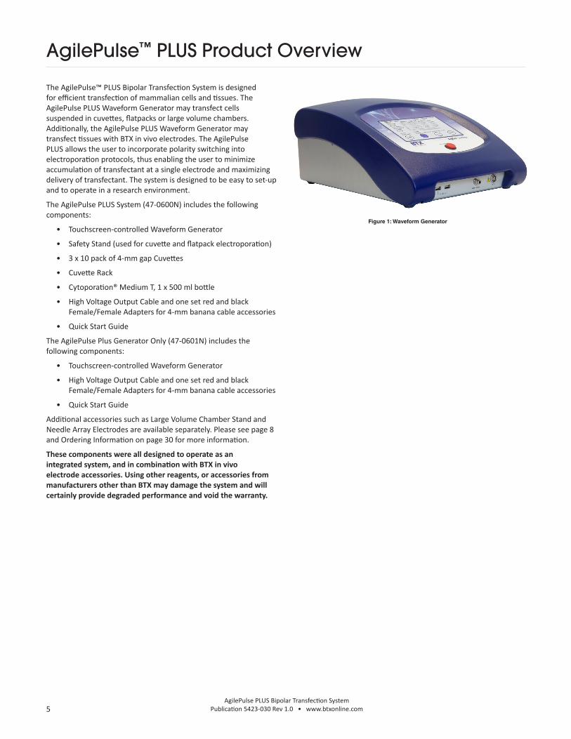
The AgilePulse™ PLUS Bipolar Transfection System is designed for efficient transfection of mammalian cells and tissues. The AgilePulse PLUS Waveform Generator may transfect cells suspended in cuvettes, flatpacks or large volume chambers. Additionally, the AgilePulse PLUS Waveform Generator may transfect tissues with BTX in vivo electrodes. The AgilePulse PLUS allows the user to incorporate polarity switching into electroporation protocols, thus enabling the user to minimize accumulation of transfectant at a single electrode and maximizing delivery of transfectant. The system is designed to be easy to set-up and to operate in a research environment.
The AgilePulse PLUS System (47-0600N) includes the following components:
• Touchscreen-controlled Waveform Generator
• Safety Stand (used for cuvette and flatpack electroporation)
• 3 x 10 pack of 4-mm gap Cuvettes
• Cuvette Rack
• Cytoporation® Medium T, 1 x 500 ml bottle
• High Voltage Output Cable and one set red and black Female/Female Adapters for 4-mm banana cable accessories
• Quick Start Guide
The AgilePulse Plus Generator Only (47-0601N) includes the following components:
• Touchscreen-controlled Waveform Generator
• High Voltage Output Cable and one set red and black Female/Female Adapters for 4-mm banana cable accessories
• Quick Start Guide
Additional accessories such as Large Volume Chamber Stand and Needle Array Electrodes are available separately. Please see page 8 and Ordering Information on page 30 for more information.
These components were all designed to operate as an integrated system, and in combination with BTX in vivo electrode accessories. Using other reagents, or accessories from manufacturers other than BTX may damage the system and will certainly provide degraded performance and void the warranty.
Figure 1: Waveform Generator
AgilePulse™ PLUS Product Overview

6AgilePulse PLUS Bipolar Transfection System
Publication 5423-030 Rev 1.0 • www.btxonline.com
System ComponentsThe AgilePulse™ PLUS Waveform GeneratorThe Waveform Generator is a computer with high voltage pulsing circuits (Figure 1). The computer runs Windows® 10 and is operated via a touch screen on the front panel. The computer has a power connection on the back panel and a power switch, emergency stop switch, electrode connector and two USB ports on the front panel. User inputs and outputs may be handled through the touch screen or via a keyboard connected to one of the USB ports.
The system is controlled by a microcontroller. The microcontroller accepts user inputs from the touch screen and produces the pulse waveforms. A second microcontroller is used as an independent audit of the waveforms produced. If the independent audit function detects a deviation from the pulse protocol, the system immediately terminates pulsing. The system also digitizes the output of the pulse voltage and pulse current monitors and calculates the resistance of the volume processed. This is a very significant quality control function that indicates the electric fields are being applied correctly.
After the cells are transfected, a complete log of all parameters is saved in internal memory. If a USB memory key is inserted, the data is also written to the key. The key may also be inserted at a later time and a particular run can be saved to the key.
AgilePulse™ PLUS System Components & Setup
Back PanelThe back panel has two connectors: an IEC Power Entry module and an Ethernet connection. The Ethernet connection is currently not functional, but is built in for expansion of future versions.
Front PanelThe following functions are on the front panel: the Mains/Line power switch (illuminated when on), the Emergency Stop button switch, two USB ports, the electrode connector, and the User Touch Screen (Figure 2).
One USB port is used for a Memory Key. The data logs that result from a transfection run are automatically stored on the key if the key is inserted.
The Emergency Stop button switch is used to stop system operation in an emergency situation. This switch immediately stops all pulsing and turns off the high voltage power supply.
Figure 2: Waveform Generator Front Panel
Caution
The Mains/Line power switch should never be turned off in an emergency situation while pulsing is in progress.
7AgilePulse PLUS Bipolar Transfection System
Publication 5423-030 Rev 1.0 • www.btxonline.com
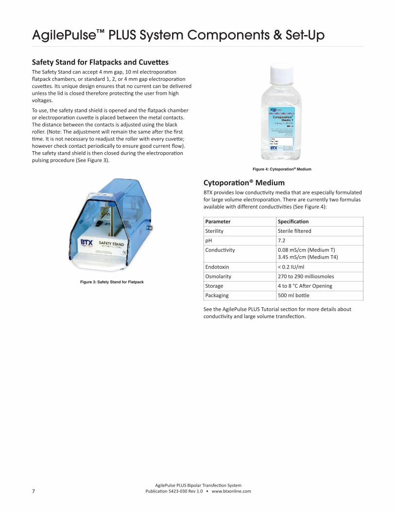
Safety Stand for Flatpacks and CuvettesThe Safety Stand can accept 4 mm gap, 10 ml electroporation flatpack chambers, or standard 1, 2, or 4 mm gap electroporation cuvettes. Its unique design ensures that no current can be delivered unless the lid is closed therefore protecting the user from high voltages.
To use, the safety stand shield is opened and the flatpack chamber or electroporation cuvette is placed between the metal contacts. The distance between the contacts is adjusted using the black roller. (Note: The adjustment will remain the same after the first time. It is not necessary to readjust the roller with every cuvette; however check contact periodically to ensure good current flow). The safety stand shield is then closed during the electroporation pulsing procedure (See Figure 3).
AgilePulse™ PLUS System Components & Set-Up
Figure 3: Safety Stand for Flatpack
Cytoporation® Medium BTX provides low conductivity media that are especially formulated for large volume electroporation. There are currently two formulas available with different conductivities (See Figure 4):
See the AgilePulse PLUS Tutorial section for more details about conductivity and large volume transfection.
Parameter Specification
Sterility Sterile filtered
pH 7.2
Conductivity 0.08 mS/cm (Medium T)3.45 mS/cm (Medium T4)
Endotoxin < 0.2 IU/ml
Osmolarity 270 to 290 milliosmoles
Storage 4 to 8 °C After Opening
Packaging 500 ml bottle
Figure 4: Cytoporation® Medium

8AgilePulse PLUS Bipolar Transfection System
Publication 5423-030 Rev 1.0 • www.btxonline.com
Large Volume Chamber & Stand The Large Volume Chamber (not included, available for purchase separately) consists of two flat and parallel plates with 6 mm spacing. There are two Luer connectors. The lower Luer port is for connecting a syringe to load cell suspension sample into chamber. This lower Luer port also has a stopcock valve to allow for opening and closing of the port during loading and removal of sample. The second Luer connector located on the top of the chamber is fitted with an air filter and acts as a vent during electroportion. The cells to be transfected are suspended in Cytoporation® Medium, mixed, and loaded in the chamber via the lower Luer lock connector using a syringe. Following cell loading into the chamber, close the valve and remove syringe. The chamber is then placed into the stand. The chamber can only be inserted into the stand in one direction. The end with the plastic protrusion must face the stand to be inserted properly. (See Figure 6)
The chamber can be used with a minimum of 2 ml and a maximum of 5 ml. The chamber should be used one time unless a validated cleaning procedure is established, documented and allowed by the protocol.
AgilePulse™ PLUS System Components & Set-Up
High Voltage Output Cable, for 4 mm Banana Cable AccessoriesThe High Voltage Cable connects the AgilePulse PLUS to in vivo electroporation accessories and adapters, such as 2-needle arrays. On one end of the cable are connectors to connect to the Generator HV Output port and Safety Interlock connectors. On the other end of the cable are red and black 4 mm male banana cables, which may be connected to BTX in vivo electrodes, such as Tweezertrodes and 2-Needle Array electrodes using Female/Female adapters (45-0088). Please see Ordering Information on page 30 for additional information on BTX electrodes and accessories.
Figure 5: High Voltage Output Cable
Figure 6: Large Volume Chamber and Stand

9AgilePulse PLUS Bipolar Transfection System
Publication 5423-030 Rev 1.0 • www.btxonline.com
AgilePulse™ PLUS System Components & Set-Up
Figure 7: Start Up Screen Display
This completes the set-up and testing of the AgilePulse PLUS System. If there is a problem, contact Technical Support for assistance.
Phone 508-893-8999, or toll free 800-272-2775
Website www.btxonline.com
Setting Up the SystemThe system set up and testing procedure is as follows:
1. Unpack the contents of the shipping box.
2. Check for obvious signs of exterior damage. If damage is noted, contact BTX Technical Support before proceeding.
3. Place the Waveform Generator on the top of a sturdy table.
4. Connect the High Voltage Output Cable, Chamber Stand Cable, or Safety Stand Cable into the HV Output and Interlock Connectors at the bottom right of the front panel.
5. Connect the mains/power cord into the back panel at the bottom right.
Initial System TestThis section will describe the process to verify mains/line cable has been installed properly and the computer boots up.
1. Connect the power cord to the mains.
2. Turn the rocker switch on the front panel to the “on” position (I).
What should happen?The rocker switch, “Power”, should illuminate and the opening touchscreen should appear within 10 seconds. If the Waveform Generator power switch fails to illuminate, then return it to the OFF position (O). Verify that the power cord is properly plugged into the wall. Verify the wall socket is functional. It may be necessary to check the fuse. See Maintenance section for instructions, proper replacement of the fuse and the correct fuse type. If a problem persists, call BTX Technical Support for assistance.
If the power is properly applied and the touchscreen is illuminated then the following display is visible:
10AgilePulse PLUS Bipolar Transfection System
Publication 5423-030 Rev 1.0 • www.btxonline.com
This chapter gives a detailed description of the operation of the AgilePulse PLUS system.
Waveform GeneratorThe Waveform Generator is controlled by a touch screen computer. It is recommended that the user touch the screen with the supplied stylus. Field entries can be made with the on-screen virtual keyboard. Alternatively, a computer keyboard may be attached via one of the USB ports.
The process flow is:
• Login
• User Data Entry
• Initialize Pulse Sequence
• Pulse Delivery
• End Process
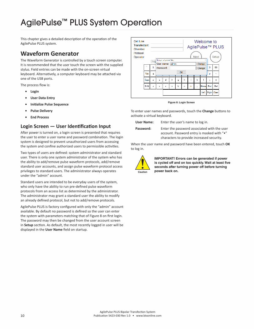
Login Screen — User Identification InputAfter power is turned on, a login screen is presented that requires the user to enter a user name and password combination. The login system is designed to prevent unauthorized users from accessing the system and confine authorized users to permissible activities.
Two types of users are defined: system administrator and standard user. There is only one system administrator of the system who has the ability to add/remove pulse waveform protocols, add/remove standard user accounts, and assign pulse waveform protocol access privileges to standard users. The administrator always operates under the “admin” account.
Standard users are intended to be everyday users of the system, who only have the ability to run pre-defined pulse waveform protocols from an access list as determined by the administrator. The administrator may grant a standard user the ability to modify an already defined protocol, but not to add/remove protocols.
AgilePulse PLUS is factory configured with only the “admin” account available. By default no password is defined so the user can enter the system with parameters matching that of Figure 8 on first login. The password may then be changed from the user account screen in Setup section. As default, the most recently logged in user will be displayed in the User Name field on startup.
Figure 8: Login Screen
To enter user names and passwords, touch the Change buttons to activate a virtual keyboard.
User Name: Enter the user’s name to log in.
Password: Enter the password associated with the user account. Password entry is masked with “•” characters to provide increased security.
When the user name and password have been entered, touch OK to log in.
Caution
IMPORTANT! Errors can be generated if power is cycled off and on too quickly. Wait at least five seconds after turning power off before turning power back on.
AgilePulse™ PLUS System Operation

11AgilePulse PLUS Bipolar Transfection System
Publication 5423-030 Rev 1.0 • www.btxonline.com
Welcome Screen — Sample Identification InputA Welcome Screen will be presented following successful user login that contains fields that should be completed before the electroporation process is initiated. Information is entered into each box by a virtual keyboard. Entering data into each field is optional. Fields may be left blank before proceeding to the next screen (See Figure 9).
To change pulse parameters, touch Setup before advancing to pulse initiation. Pre-programmed protocols are selected from a drop-down menu on the Protocol screen (see Protocol Setup, page 11). Information entered into the data fields will be retained when returning from Setup. The data fields are cleared upon completion of pulse delivery.
When all of the fields are filled in and the desired protocol has been selected, pulse delivery is initiated by touching Next to advance to the Pulse Delivery screen.
Figure 9: Welcome Screen
Pulse Delivery Screen: Functions and OperationThe Pulse Delivery screen is used to control the delivery of electroporation pulses to the sample. The Pulse Delivery screen also provides visual feedback before, during, and after pulse delivery.
Procedure for Pulse Delivery:
1. Prepare Sample
• For in vitro electroporation using the Large Volume Electroporation Chamber (47-0204N), large volume Flatpack Chamber (47-0206), or BTX Cuvettes Plus (45-0136), load with cells and transfectant (such as plasmid DNA) suspended in Cytoporation Medium, keeping within the specified volume range for the chamber.
• For in vivo electroporation with BTX electrodes, inject target tissue with desired volume of transfectant suspended in 0.25 to 1X PBS.
2. Make proper connections between generator, electrode, and sample. The chamber holder, Safety Stand, or HV Output Cable should be connected to the Generator HV output and Interlock Connectors.
• To use the Large Volume Electroporation Chamber, insert the chamber in the Chamber Stand. Do not insert fingers or other objects into the Chamber Holder.
• To use a Flatpack Chamber and Cuvette Safety Stand, insert Flatpack or Cuvette into the Safety Stand and rotate black tightening wheel until the electrodes are making firm contact with the Flatpack or Cuvette. The correct amount of tension will allow the chamber to slide in and out of the Safety Stand with some resistance.
• For in vivo electroporation with BTX electrodes, connect the desired electrode to the HV Output Cable. For electrodes with Male 4 mm banana cables, use Female/Female adapters (45-0088) to connect the electrode to the HV Output Cable. Position the electrode on the target tissue as desired.
3. Please refer to Figure 10: Pulse Delivery Screen — Pre-Pulse for steps 3 through 5. Touch the Load button. The system will automatically deliver a short low voltage pulse to estimate the load resistance. If the resistance is too low, the pulse will not be delivered. If the resistance is within acceptable limits, the Ready button will turn yellow.
4. Touch the Ready button. The system will charge the high voltage capacitors to the set voltage. When the system is charged, the Start button will turn yellow.
5. Touch the Start button. The system system will deliver the set pulse protocol. When delivery is complete, the Done button will turn green and the pulse log will be displayed in the text box, as pictured in Figure 11: Pulse Delivery Screen — Post-Pulse.
6. Touch the Done button to return to the Welcome screen. The identification fields will be reset. Repeat the procedure for each pulse delivery (See Figure 11).
Figure 10: Pulse Delivery Screen — Pre-Pulse
AgilePulse™ PLUS System Operation

12AgilePulse PLUS Bipolar Transfection System
Publication 5423-030 Rev 1.0 • www.btxonline.com
User Account MaintenanceThe user account maintenance screen is accessed from the Welcome screen:
Touch Setup
Touch User
User accounts and privileges are managed from this screen. While standard users will only see the Active User section, and thus will only be able to change their password, the system administrator has access to account properties for all standard users.
As an administrator, a new user account can be adding by pressing the Add New User button. Once the account is created the new user is assigned read-only access to all of the pulse protocol waveforms on the system. The administrator may then select individual protocols and provide more access by giving both read and write privileges, or they may restrict access to a protocol altogether by giving the user no access at all. When a user is not given any protocol access they will not be able to see or select it from the Protocol screen when they log in under their own user name. When protocols are added through the Protocol screen after a standard user account has already been created, all user accounts in the system will receive read-only access to the new protocol.
The administrator also has the ability to change a user’s password. This is ideal for situations in which the user forgets his/her password and thus needs the password to be reset in order to log in again (See Figure 12).
Caution
IMPORTANT! The changes made on this screen will only be permanently saved when the HOME button is pressed to go back to the Welcome screen. If modifications are made and system power is turned off while still viewing the screen, all changes will be lost.
Figure 12: User Account Screen
AgilePulse™ PLUS System Operation
Figure 11: Pulse Delivery Screen — Post-Pulse

13AgilePulse PLUS Bipolar Transfection System
Publication 5423-030 Rev 1.0 • www.btxonline.com
Protocol SetupPulse protocols can be viewed and/or modified on the Protocol Screen which is accessed from the Welcome Screen:
Touch Setup
Touch Protocol
Parameters for up to five pulse groups are set by selecting the appropriate box and scrolling through the available values. Subsequent groups are activated by selecting more than one pulse in the number field and are conversely deactivated by selecting zero pulses in the number field. The adjusted protocol is saved to internal memory when the Home button is touched (See Figure 13).
• Amplitude defines the voltage of the pulses in each group.
• Duration defines the length of pulses in each group.
• Pulse Interval defines the inter-group interval (pulse interval time within a single group).
• Group Interval defines the intra-group interval (pulse interval time between one group and the next group. Group Interval also defines the interval in the middle of a group when polarity flip settings are turned on.
• Number defines the number of pulses in each group.
• Polarity defines the directionality of the electrical current flow during the pulses. Options include Positive, Negative, Flip - → +, and Flip + → - . For the Flip polarity options, the first half the pulses of the group will be delivered in the one polarity, then the second half of the pulses of the group will be delivered in the opposite polarity. For Flip polarity groups with an odd number of pulses, the extra pulse will be delivered prior to the Flip. For example, a Flip + → - group with pulse number set to 3 will have 2 positive polarity pulses followed by one negative polarity pulse.
Only the system administrator has access to the Add New and Remove buttons which create new protocols and delete existing protocols respectively. When a new protocol is created, all user accounts in the system receive read-only access to it. The administrator can customize user access privileges for each protocol by navigating to the User Account Maintenance screen, (see page 10).
There are limitations on the range of parameters and interaction between various parameters.
The following rules must be observed:
Pulse Amplitude
100 to 1200 Volts
10 Volt Steps Pulse Width Range
50 µs to 1000 µs
100 to 300 Volts
10 Volt Steps Pulse Width Range
1 ms to 10 ms
Pulse Drop
Less than 2% of power supply voltage at 100 ohms
Less than 8% of power supply voltage at 10 ohms
Pulse Widths in ms
0.05, 0.10, 0.30, 0.40, 0.50, 1, 2, 3, 4, 5, 10
Pulse Width Droop
<7.5%
Pulse Intervals in ms
0.2, 0.3, 0.4, 0.5, 1, 2, 3, 4, 5, 10, 20, 30, 40, 50, 100, 200, 300, 400, 500, 1000
Inter-group
Pulse interval must be ≥2X pulse width witha 0.2 ms minimum
Intra-group
Group interval must be ≥2X pulse width with a 0.2 ms minimum
Time between end of pulse N and beginning of pulse N+1 must be >-0.04*ln(Vn+1/Vn)
If the signal polarity is changing within the current group or between the current group and the next, Group interval must be a minimum of 50 ms
Number of Pulses
1 to 10 in steps of 1
Polarity SettingsPositive, Negative, Flip Positive → Negative, Flip Negative → Positive. Note: Flip Positive → Negative and Negative → Positive are not available if the group is set to have only one pulse.
Number of Groups
1, 2, 3, 4 or 5
Caution
IMPORTANT! The changes made on this screen will only be permanently saved when the HOME button is pressed to go back to the Welcome Screen. If modifications are made and system power is turned off while still viewing the screen, all changes will be lost.
Figure 13: Protocol Screen
AgilePulse™ PLUS System Operation

14AgilePulse PLUS Bipolar Transfection System
Publication 5423-030 Rev 1.0 • www.btxonline.com
Log File MaintenanceThe Log File Maintenance screen is accessed from the Welcome screen:
Touch Setup
Touch Logs
All previous transfection run logs can be retrieved and saved onto a USB Key or deleted from internal memory. The interface consists of a series of chronological sub-folders from which the user is allowed to double-tap on the touchscreen to descend through the hierarchy. The standard naming sequence is Year, Month, Day, followed by special folders with the time of day. These time folder icons show a “hand” underneath, meaning they contain all files generated from a single run. The “ ” folders allow the user to return to the previous level of hierarchy.
Special time folders display basic information on the right hand side of the screen when selected. Identification numbers, time of day, and status completion indicators help the user find the correct transfection run to download.
When selected by a single tap on the touchscreen icon, any level of hierarchy can be saved to a USB key inserted in the front panel by pressing the Save button. The hierarchy structure will be maintained and copied to the USB key. The Delete button is also available to remove the hierarchy from internal memory. This deletion is permanent and the lost files cannot be recovered.
Caution
The Saving and Deleting processes are slow and dependent on the number of files being saved or deleted. Do not use USB keys that will attempt to upload software onto the computer drive. Keys with <1 GB memory are recommended.
Figure 14: Log File Maintenance Screen
AgilePulse™ PLUS System Operation

15AgilePulse PLUS Bipolar Transfection System
Publication 5423-030 Rev 1.0 • www.btxonline.com
Electroporation Protocol Delivery LogsAll collected data from the delivery is automatically stored on the internal Flash Memory and an inserted USB key under a unique chronological directory structure. Included items are an XML file containing raw detailed system and runtime data, a text log with basic runtime data, and a comma separated CSV file containing pulse monitor data.
The directory structure is constructed in a “AgilePulse MAX\Log\<Year>\<Month>\<Day>\<Time>” hierarchy format. A maximum of 20,000 delivery logs can be stored on the internal system memory.
AgilePulse™ PLUS System Operation
Raw Data (DV <Date> <Time>.xml)
Text Log (DV <Date> <Time>.log)
CSV Data (DV <Date> <Time>.csv)
Start and Stop Date • •
Start and Stop Time • •
Field 1 • • •
Field 2 • • •
Field 3 • • •
Process Completion Type • •
Set Pulse Voltage and Duration Parameters • • •
Set and Monitor Pulse Polarity • •
Average Monitor Pulse Voltage •
Average Monitor Pulse Current •
Average Monitor Pulse Resistance •
All Monitor Pulse Voltage Samples • •
All Monitor Pulse Current Samples • •
Monitor Width of Each Pulse • • •
Monitor Interval of Each Pulse • • •
Check Reading • •
System Serial Numbers •
System Software Versions •

16AgilePulse PLUS Bipolar Transfection System
Publication 5423-030 Rev 1.0 • www.btxonline.com
Text LogThe text log contains the same information that appears on the Delivery Process screen after completion. Text log data is summarized in an easy to read format and is designed to provide quick feedback regarding the delivery completion. An example log printout is presented in Figure 15.
Field Description
Pulse Pulse number
VSet Voltage programmed to high voltage power supply
VMon Voltage monitored during pulse
IMon Current monitored during pulse
RMon Equivalent load resistance calculated from voltage and current monitors R = V / I
DurSet Pulse duration programmed to waveform generator
DurMon Pulse duration monitored by independent time-auditor system
IntSet Pulse interval programmed to waveform generator
IntMon Pulse interval monitored by independent time-auditor system
AgilePulse™ PLUS System Operation
Date Start: 10/23/2019 7:16:30 AM (10/23/2019 11:16:30 AM GMT)System Serial Number:
Cell Line: NATransfectant: NAChamber: NAOperator: admin
Final Completion Code: 0 (Success)
++++++++++++++++++++Cycle 1Cycle Start: 10/23/2019 7:16:30 AM (10/23/2019 11:16:30 AM GMT)Process Completion Return Code: 0 (Success)
Pulse VSet PVMon PIMon RMon DurSet DurMon IntSet IntMon1 +100 +96 1.02 94 10.000 9.974 50.000 49.8532 -100 -97 1.02 95 10.000 9.972 50.000 49.8543 +100 +101 1.03 98 0.050 0.050 0.200 0.2034 +100 +101 1.03 98 0.050 0.050 50.000 49.8495 -100 -101 1.10 92 0.050 0.050 0.200 0.2036 -100 -101 1.10 92 0.050 0.050 0.200 0.2037 -100 -101 1.10 92 0.050 0.050 50.000 49.8568 +100 +100 1.10 91 0.050 0.050 0.200 0.2039 +100 +100 1.10 91 0.050 0.050 50.000 49.85010 -100 -100 1.10 91 0.050 0.050 0.200 0.20211 -100 -100 1.10 91 0.050 0.050 50.000 0.000
Pre-pulse Estimated Load: 101 OhmsAverage Monitored Pulse Load: 92 Ohms
++++++++++++++++++++
Date Stop: 10/23/2019 7:16:36 AM (10/23/2019 11:16:36 AM GMT)Time Elapsed: 00:00:06
Figure 15: Text Log Example

17AgilePulse PLUS Bipolar Transfection System
Publication 5423-030 Rev 1.0 • www.btxonline.com
CSV DataDetailed pulse information is exported from raw data and formatted to a standard comma separated file, primarily meant to be imported into Microsoft Excel® for further user manipulation. As an example, in Figure 16, a chart was made to display the monitored amplitude samples of three 100 microsecond pulses run at 5 kHz. In this case, each pulse contains eight amplitude samples.
Figure 16: Sample Amplitude Analysis
AgilePulse™ PLUS System OperationA
mp
litud
e (v
olt
s)
Time (ms)
Time vs Amplitude
0-0.1 0 0.1 0.2 0.3 0.4 0.5 0.6
50
100
150
200
250
300
350
400
450
500

18AgilePulse PLUS Bipolar Transfection System
Publication 5423-030 Rev 1.0 • www.btxonline.com
Delivery Completion Return CodesSeveral return codes are available following protocol delivery describing how it took place.
Return Code Description0 Successful completion (Normal Operation)
1 Emergency Flash memory storage failure
2 Waveform protocol data integrity verification error
3 Waveform protocol mode not recognized
4 Protocol voltage below minimum specification
5 Protocol voltage above maximum specification
6 Protocol pulse width below minimum specification
7 Protocol pulse width above maximum specification
8 Protocol pulse interval below minimum specification
9 Protocol pulse interval above maximum specification
10 Protocol pulse number below minimum specification
11 Protocol pulse number above maximum specification
12 Protocol has a zero pulse group in between two non-zero pulse groups
13 Protocol pulse settings exceed maximum duty cycle
14 Low voltage power supply failure (Hard system turn-off)
15 High volt power supply voltage above maximum voltage
16 High volt power supply maximum current draw
17 Pulse voltage monitor detected off-zero voltage while no pulse was active
18 Pulse voltage monitor below maximum droop specification
19 Pulse voltage monitor above maximum overshoot specification
20 Pulse current monitor below minimum specification
21 Pulse current monitor above maximum specification
22 Independent time-audit system failed to respond to query
23 Independent time-audit system detected less pulses than expected
24 Independent time-audit system detected more pulses than expected
25 Independent time-audit system exceeded maximum measurable pulse number
26 Independent time-audit system detected excessive pulse duration variance
27 Independent time-audit system detected excessive pulse interval variance
28 Independent time-audit system data integrity verification failure
29 Reset button on front panel triggered
30 Control system watchdog timeout
251 High voltage timeout
252 Load estimation timeout
253 Delivery process was terminated prematurely
254 Control system experienced a system reset of unknown source
255 Load estimate outside of allowable range
AgilePulse™ PLUS System Operation
19AgilePulse PLUS Bipolar Transfection System
Publication 5423-030 Rev 1.0 • www.btxonline.com
Transfection ProcessThe transfection process consists of the following steps:
1. Preparing the polynucleotide
2. Preparing the cell suspension
3. Filling the chamber
4. Electroporation
5. Handling after electroporation
Preparing the PolynucleotideTransfection efficiency is often directly related to polynucleotide concentration. However, the optimum concentration may vary depending on the material to be transfected. Some optimization will be required for each combination of polynucleotide and cell type. It is recommended that the polynucleotide be prepared in nuclease-free water rather than TE or other ionic buffers in order to maintain the low conductivity environment necessary for large volume transfection. The following are typical concentrations of polynucleotides that are used for electroporation:
• DNA 10 to 100 µg/mL
• mRNA 10 to 100 µg/mL
• siRNA 100 nM to 1 µM
• Oligonucleotides 100 nM to 20 µM
Preparing Cell Suspensions for Large Volume TransfectionThe following is a standard procedure for preparing cells for large volume electroporation. Cell washes may be carried out at 4°C. However, it is recommended that electroporation in Cytoporation medium be carried out at room temperature.
1. Harvest cells from several T150 flasks, roller bottles or fermenter.
2. Centrifuge cells 300 x g for 10 minutes.
3. Pour off supernatant, resuspend cells and add 10 ml Cytoporation® Medium T.
4. Centrifuge cells 300 x g for 10 minutes.
5. Pour off supernatant, resuspend cells and add 10 ml Cytoporation® Medium T.
6. Centrifuge cells 300 x g for 10 minutes.
7. Resuspend cells at 10 to 100 million cells/ml in Cytoporation Medium T or T4.
8. Add polynucleotide (DNA or RNA) to desired concentration.
Efficient transfection can be achieved with cell densities ranging from 10 million cells/ml to 100 million cells/ml. It is important to remember that at high cell densities, leakage of ions from the cells during electroporation can contribute to significant increases in conductivity during pulse delivery.
AgilePulse™ PLUS In Vitro Electroporation Protocol
Filling the ChamberThe Large Volume Electroporation Chamber can be filled through one of the Luer lock ports. It is recommended that a sterile syringe be used for filling and emptying of the chamber.
The Large Volume Electroporation Chambers may be re-used if properly cleaned after each use. Chambers can be sanitized by soaking in 1 M NaOH (4% solution) for 10 minutes, then rinsing liberally with sterile water. Chambers are not autoclave-safe. Alternative cleaning procedures must be validated prior to use.
Large Volume 4-mm gap, 10 ml Flatpacks may be filled using the provided metal syringe loading tip. Large volume Flatpacks are intended for single-use only. However the metal syringe loading tip may be sanitized by soaking in 1 M NaOH (4% solution) for 10 minutes, then rinsing liberally with sterile water.
Electroporation Cuvettes may be filled using a micropipette or sterile plastic thin-tipped transfer pipettes. Cuvettes are intended for single-use only.
20AgilePulse PLUS Bipolar Transfection System
Publication 5423-030 Rev 1.0 • www.btxonline.com
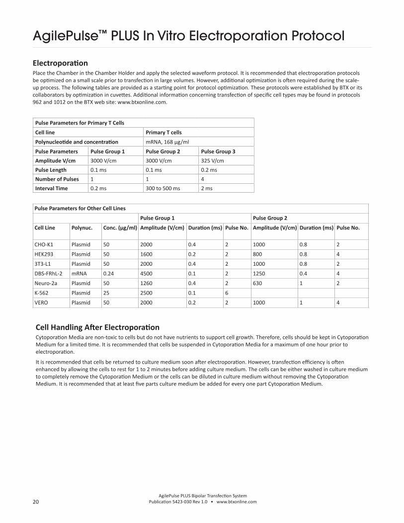
ElectroporationPlace the Chamber in the Chamber Holder and apply the selected waveform protocol. It is recommended that electroporation protocols be optimized on a small scale prior to transfection in large volumes. However, additional optimization is often required during the scale-up process. The following tables are provided as a starting point for protocol optimization. These protocols were established by BTX or its collaborators by optimization in cuvettes. Additional information concerning transfection of specific cell types may be found in protocols 962 and 1012 on the BTX web site: www.btxonline.com.
Cell Handling After ElectroporationCytoporation Media are non-toxic to cells but do not have nutrients to support cell growth. Therefore, cells should be kept in Cytoporation Medium for a limited time. It is recommended that cells be suspended in Cytoporation Media for a maximum of one hour prior to electroporation.
It is recommended that cells be returned to culture medium soon after electroporation. However, transfection efficiency is often enhanced by allowing the cells to rest for 1 to 2 minutes before adding culture medium. The cells can be either washed in culture medium to completely remove the Cytoporation Medium or the cells can be diluted in culture medium without removing the Cytoporation Medium. It is recommended that at least five parts culture medium be added for every one part Cytoporation Medium.
Pulse Parameters for Primary T Cells
Cell line Primary T cells
Polynucleotide and concentration mRNA, 168 µg/ml
Pulse Parameters Pulse Group 1 Pulse Group 2 Pulse Group 3
Amplitude V/cm 3000 V/cm 3000 V/cm 325 V/cm
Pulse Length 0.1 ms 0.1 ms 0.2 ms
Number of Pulses 1 1 4
Interval Time 0.2 ms 300 to 500 ms 2 ms
AgilePulse™ PLUS In Vitro Electroporation Protocol
Pulse Parameters for Other Cell Lines
Pulse Group 1 Pulse Group 2
Cell Line Polynuc. Conc. (µg/ml) Amplitude (V/cm) Duration (ms) Pulse No. Amplitude (V/cm) Duration (ms) Pulse No.
CHO-K1 Plasmid 50 2000 0.4 2 1000 0.8 2
HEK293 Plasmid 50 1600 0.2 2 800 0.8 4
3T3-L1 Plasmid 50 2000 0.4 2 1000 0.8 2
DBS-FRhL-2 mRNA 0.24 4500 0.1 2 1250 0.4 4
Neuro-2a Plasmid 50 1260 0.4 2 630 1 2
K-562 Plasmid 25 2500 0.1 6
VERO Plasmid 50 2000 0.2 2 1000 1 4

21AgilePulse PLUS Bipolar Transfection System
Publication 5423-030 Rev 1.0 • www.btxonline.com
Note: These are recommended electroporation settings. Reducing the pulse interval time below 50 ms in group 2 may lead to insufficient time for the instrument to decrease voltage and result in an aborted protocol with Delivery Completion Return Code 19 displayed (Pulse voltage monitor above maximum overshoot specification). Increasing pulse interval time is recommended to resolve this issue. Please see page 18 for a full list of Delivery Completion Return Codes.
AgilePulse Set Up• Connect the the needle array handle cable to the AgilePulse
HV output cable using Female/Female adapters.
• Turn on AgilePulse system.
• Program the electroporation settings as outlined in table above.
• Input animal ID information in the Cell Line field and Transfectant ID information in the Transfectant field on the instrument Welcome screen.
• Insert needle array electrode tip into needle array handle. Inspect the needle array electrode to ensure that the electrode needles are not bent and are the same length.
• Optional: Connect USB flash drive to one of the USB ports on the AgilePulse generator for copy of log data on flash drive. Log data is also stored on Internal Memory on AgilePulse generator automatically.
Injection• Prepare transfectant and adjuvant if desired in 0.25 to 1X
PBS. Suggested plasmid DNA concentration range is 1 to 4 μg/ml (recommended starting concentration is 2 μg/ml).
• To aid in accurate administration of the procedure and minimize the potential for startle reflex, anesthetize animal as per veterinarian recommendations. The subject should be anesthetized to a level where it is not responsive to a strong toe pinch or other equivalent stimulus.
• Clip hair or depilate to expose target tissue.
• Clean site with 70% alcohol and remove excess alcohol with gauze.
• Anesthetized animal should be oriented to allow for easy exposure of target tissue.
• Obtain tuberculin syringe(s), 3/10 cc (BD model 328431), loaded with transfectant mixture. Use a 30-gauge needle.
Electroporation Settings
Group Voltage Pulse Length Pulse Interval No. Pulses Polarity
Voltage Groups 1 560 V 0.05 ms 0.2 ms 1 Positive
2 560 V 0.05 ms 50 ms 1 Positive
3 140 V 10 ms 20 ms 8 Positive OR Flip + → -
Desired Electrical Field Strength 1125 volts/cm
AgilePulse™ PLUS In Vivo Electroporation Protocol
• For muscle electroporation, fit the syringe with P10 tubing to ensure an even depth of insertion into the muscle targeted.
• For skin electroporation, insert needle tip 2 to 3 mm just under the skin (needle should be visible) and slowly inject DNA into site. A clear bleb in the skin should be visible post-injection.
• For muscle electroporation, insert needle tip into the muscle at desired depth and slowly inject DNA into site.
• Inject 20 to 30 μl transfectant solution.
• Repeat the procedure on the other sites if necessary.
Electroporation • Insert needle electrode so the injection site is placed
between the two needle rows. Begin the process by pressing the Next button. This will take you to a screen with a series of buttons.
• Press the Load button. Read the “load reading” on the right-hand side of the screen. If it is below 100 ohms, then the electrode is inserted far enough. If above 2000 ohms, insert the needles deeper in the tissue.
• After correct insertion has been verified, sequentially press the remaining buttons as they fill-in to start electroporation sequence.
• Keep pushing electrode firmly against animal until pulsing stops.
• Remove electrode after delivery of pulses.
• Check the log file to verify proper delivery.
• Repeat electroporation as needed, then press Done icon to return to the main screen.
• Observe animal and keep warm until it recovers from anesthesia. Put animal back into its cage.
Target Tissue: Animal Skin/Intradermal or Tibialis Muscle; Small or Large animal
Transfectant: Plasmid DNA, mRNA, or Protein, or other desired molecule of interest
Electrode Accessory: 2-Needle Array, 5 mm gap (45-0168)

22AgilePulse PLUS Bipolar Transfection System
Publication 5423-030 Rev 1.0 • www.btxonline.com
ApplicationsThe AgilePulse PLUS system is used to deliver material into cells and tissues using pulsed electric fields. It is a system capable of treating up to 10 ml of cell suspension in vitro or capable of transfecting tissues in vivo using BTX in vivo electrodes. The AgilePulse PLUS system was specifically designed for the transfection of cells with polynucleotides. However, a variety of charged material can potentially be delivered into cells.
DNA/RNA Delivery into Cells Using ElectroporationGeneral Electroporation DiscussionElectroporation uses pulsed electric fields to create microscope pathways (pores) in bio-membranes. Their presence allows macromolecules, ions, and water to pass from one side of the membrane to the other. As the right side bar shows, when the electric field is applied the ions inside and outside the cell membrane migrate. As the charge builds up on either side of the membrane, pores form that permit material outside of the cell to enter. If the electric field is promptly removed, the pores close and the membrane reseals. If the electric field duration is too long, the pores increase in size and number and the cell is killed.
Electroporation was first used to introduce small molecules into cells in the early 1980s and quickly became a popular research method. By the late 1980s electroporation applications were being developed for multi-cellular tissues. In the early 1990s Lluis Mir of the Institute Gustave-Roussy was the first to use electroporation in a human trial to treat external tumors.
Efficient electroporation depends on proper selection of electric field waveforms. Pores begin to form in about a microsecond and reseal in seconds to minutes. Therefore, duration of the applied electric fields are typically in the range of tens of microseconds to tens of milliseconds.
Induction of electropores is affected by a number of factors. Pores are induced when the product of the pulse amplitude and the pulse duration is above a lower limit threshold. Normal cell-to-cell biological variability can cause some cells to be more sensitive to electroporation than other cells. Although other factors are involved, the lower limit threshold for a particular cell type is largely dependent on the reciprocal of cell size (See Figure 17).
Before Field Applied
Field Applied-Ions Move
Field Applied-Pathways Form
Field Removed-Membrane Seals
Figure 17: Electroporation
AgilePulse™ PLUS Tutorial
IonsGene
CellMembrane

23AgilePulse PLUS Bipolar Transfection System
Publication 5423-030 Rev 1.0 • www.btxonline.com
PulseAgile ElectroporationPulseAgile™ electroporation differs from standard electroporation in that it allows control of pulse parameters from pulse to pulse within a single delivery sequence. This means that values for pulse voltage, pulse duration, interval between pulses, and number of identical pulses in a subset can be programmed to change during a series of pulses. In practice, PulseAgile™ is usually used to deliver high electric field pulses of short duration followed by lower electric field pulses of longer duration. This method increases electroporation efficiency in numerous applications and is covered by U.S. patents 6,010,613 and 6,078,490.
Physical principles of importance to electroporation are:
1. Applied pulsed electric fields of optimal magnitude and duration induce a transient state of permeability in cells immersed in that electric field (Neumann, 1972).
2. An applied electric field can move charged particles in an ionic medium by electrophoresis (Moyer, 1936).
3. An electrical current is required to maintain an electric field in an ionic medium (Ohm’s Law).
4. Heat production by an electrical current in an ionic medium is proportional to the square of the current (Joule’s First Law).
These principles can be used to optimize electroporation. All four of these physical processes are active during the entire time that electric fields are applied to the area around cells. However, they vary in importance at different times during electroporation.
As charge accumulates at the membrane, the voltage across the membrane increases. Neumann et al. (1989) described the equation that relates the transmembrane voltage (TMV) to electric field intensity:
Pores in the membrane will begin to form as the voltage increases from its quiescent value of a few tenths of a volt to more than 0.5 volts. To produce a TMV of 1 volt across the membrane of a cell with 7 µm radius, the required electric field intensity is:
where:
E = electric field intensity in volts/cm
r = the cell radius in cm
a = angle off the center line
The number of pores and effective pore diameter increase as the product of pulse amplitude and duration increase. At the upper limit threshold, pore diameter and total pore area become too large for the cell to repair by any spontaneous or biological process. The result is irreversible damage to the cell or cell lysis.
Another important point to consider is the generation of heat during electroporation. Heat production is directly related to current intensity which is, in turn, dependent on the conductivity of the material through which the electric field is applied. Standard saline solutions such as PBS and many tissue culture media are highly conductive and, thus, will generate considerable amounts of heat when used in cell electroporation. Excessive heating can be detrimental to cell viability. The effects of heating can be reduced by using a low conductivity medium such as BTX’s Cytoporation® medium to resuspend cells prior to electroporation (see also Importance of Medium Conductivity in Electroporation on page 7 for other important issues related to conductivity).
Although electroporation is an effective method for introducing macromolecules into cells, the biological mechanisms by which cells become electroporated are not completely understood. Therefore, the development of specific protocols for particular applications is usually achieved by empirical adjustment of pulse parameters (i.e. amplitude, duration, pulse number, and interpulse interval).
TMV 3⁄2= - E r | cos a |
2⁄3= = 950 volts / cm17 *10-4
E -
Figure 18: Transmembrane Voltage
AgilePulse™ PLUS Tutorial

24AgilePulse PLUS Bipolar Transfection System
Publication 5423-030 Rev 1.0 • www.btxonline.com
Minimizing Heat Production with WaveformJoule’s first law states that ohmic or Joule heating is proportional to electrical resistance times the square of the current. Joule heating is a common cause of cell death during electroporation, so excessive increases in temperature due to this effect should be avoided. Following enough poration of the cell membrane to physically allow transfectant entry, a subsequent reduction in electric field will continue to move the transfectant by way of electrophoresis while generating much less heat. For example, a half decrease in electric field will reduce heat generated four fold.
Putting the AgilePulse™ Concepts TogetherA summary of the proportional relationships of physical factors during electroporation are:
1. The area of a cell permeabilized by electroporation is positively correlated to the magnitude of an applied electric field (less than linearly because of the cosine in the formula).
2. The movement of a charged molecule (such as DNA) in a solution in an electric field is linearly related to the total applied charge.
3. Heat produced during electroporation is proportional to the square of the applied current (or of the applied voltage if the electrical resistance is constant).
Given these relationships, maximum cell permeability and maximum DNA delivery can be achieved by delivering a series of brief high electric field pulses at the beginning of electroporation to induce permeability in a large area of the cells followed by delivery of a series of lower electric field pulses to induce maximum movement of DNA with minimal heating.
Induction of a State of PermeabilityApplying an electric field across a cell causes a redistribution of internal ions because cell membranes act as insulators. Ions move according to their charge within the electric field, but remain trapped within the cell thus accumulating at the poles in line with the electric field. This polar accumulation of ions within the cell creates an electrical potential across the cell membrane. When the transmembrane voltage exceeds a threshold of approximately one volt, conformational changes within the membrane induce a state of permeability.
The potential across a cell membrane is not equal along the entire surface of the cell. It is highest when the surface of the cell membrane is perpendicular to the electric field (in line with the electric field) and lowest when the surface of the cell membrane is parallel or tangential to the electric field (out of line with the electric field). The variation of transmembrane potential in an electric field as described above is related to the cosine of a with the greatest transmembrane potential at the poles of the cells in line with the electric field and the least transmembrane potential 90 degrees from the poles (See Figure 18).
Increasing the electric field from one value above threshold to a higher value above threshold will induce permeability in a larger surface area of the cell. This is because of the dependence upon the cosine shown in the formula above. Thus, high electric fields are used in first pulses to permeabilize a large area of the cell membrane.
The permeabilized area on each end of a cell will be asymmetrical. It will be slightly larger on the anode (+) side than the cathode (-) side. This is because the cell has a slight natural negative charge across its membrane (Golzio, 2002).
Movement of DNA or RNA Across Cell MembranesThe principle force influencing movement of polynucleotides across a cell membrane during electroporation is electrophoresis (Klenchin, 1991). This has been shown both in vitro (Andreason, 1989) and in vivo (Satkauskas, 2002). Electrophoresis is the movement of charged particles in a solution in response to an electric field. Movement of particles by electrophoresis is proportional to the total applied charge, which is in turn proportional to the magnitude of the electric field times the duration of the electric field. Assuming other factors such as solution viscosity are constant, the movement is linearly related to the total charge. This means that total distance traveled is approximately the same when half of a given electric field is applied for twice a given time.
AgilePulse™ PLUS Tutorial

25AgilePulse PLUS Bipolar Transfection System
Publication 5423-030 Rev 1.0 • www.btxonline.com
Importance of Medium Conductivity in ElectroporationWhen using standard cuvettes in electroporation, medium conductivity is generally not a critical issue. However, for large volumes medium conductivity quickly becomes critical. As the volume of cell suspension gets larger the resistance of the bulk solution gets smaller. This relationship can be represented mathematically as follows:
R *r= gap
ohmsarea
Conductivity s= 1 Siemens/cm
(often converted to milliSiemens / cm)resistivity
where:
R is the resistance in ohms of the solution in the chamber.
gap is the spacing between two parallel electrodes.
area is the active area of the electrodes that are in contact with the cell suspension (the areas of the two electrodes are identical).
r is the resistivity of cell suspension in the chamber with units ohm-cm.
where:
s is in S/cm (if in mS/cm then s/103, if in µS/cm then s/106).
gap is in cm.
volume is in ml.
Engineers and physicists generally use resistivity, biologists often use conductivity:
Since it is often difficult to make a direct measurement of the active area of the electrodes in a cuvette or electroporation chamber, a more practical equation is needed. The volume of cell suspension added to a cuvette can be represented as follows:
1⁄s= ohmsgap2
volumeR
AgilePulse™ PLUS Tutorial

26AgilePulse PLUS Bipolar Transfection System
Publication 5423-030 Rev 1.0 • www.btxonline.com
The table below provides some insight into how conductivity and volume affect the resistance in an electroporation chamber. Examples are given for a standard 4 mm cuvette with a maximum volume of 800 μl, a 6 mm gap sterile chamber with a maximum volume of 6 ml, or a 4 mm flatpack with a maximum volume of 10 ml. The conductivities of Opti-MEM I and RPMI-1640 are similar to the conductivity of PBS.
Medium* Conductivity, S (mS/cm) Gap (cm) Volume (mL) Resistance, R (ohms) Pulse Current @ 1000 V (Amps)
T 0.08 0.4 0.8 2500 0.5
T-4 3.4 0.4 0.8 59 17
Opti-MEM I N/D 0.4 0.8 22 45
RPMI 1640 N/D 0.4 0.8 15.8 63
PBS 16.6 0.4 0.8 12 83
T 0.08 0.4 5 400 3
T-4 3.4 0.4 5 9.4 106
PBS 16.6 0.4 5 1.9 519
T 0.08 0.6 2 2250 0.4
T-4 3.4 0.6 2 52.9 19
PBS 16.6 0.6 2 11 92
T 0.08 0.6 6 750 1.3
T-4 3.4 0.6 6 17.6 57
PBS 16.6 0.6 6 4 277
For practical reasons, as the bulk of volume to be electroporated increases, the conductivity must be decreased. Otherwise, current requirements will rapidly exceed available capacity.
Note: High conductivity buffers (indicated in red font) are not recommended for use with the AgilePulse PLUS system.
AgilePulse™ PLUS Tutorial

27AgilePulse PLUS Bipolar Transfection System
Publication 5423-030 Rev 1.0 • www.btxonline.com
Cytoporation® Medium PropertiesConductivityThe conductivity of most common electroporation buffers range from 10 to 20 mS/cm; these conductivities are too high for electroporation of large volumes. Cytoporation media were developed to address this problem. Although very low conductivity is desired for large volumes, experimental data indicate that some cell types require a moderately conductive environment to achieve optimal transfection efficiency. The trade-off between maximum volume and optimal efficiency must be considered when choosing a medium for large volume electroporation.
Media FormulasThere are two Cytoporation formulas currently available: Cytoporation Medium T at 0.08 mS/cm and Cytoporation Medium T-4 at 3.45 mS/cm. These media are produced under strict standards and are listed with the FDA under Master File Number MAF-1508.
Some cell types can be sensitive to the conductivity of the electroporation buffer. Therefore, optimization is usually required to determine the most effective formulation for a given cell type.
Another point to consider is that ions within the cells will leak out when the cell membranes become porated. This will contribute to an increase in conductivity of the extracellular solution during the course of electroporation. This effect is especially important to consider when working with high concentrations of cells (i.e. 100 million cells/ml).
AgilePulse™ PLUS Tutorial
Other Important Cytoporation® Medium PropertiesIn addition to low conductivity, Cytoporation Media have other properties that contribute to successful electroporation such as physiological pH and normal osmolarity. The pH is moderately buffered, but addition of any reagents that could affect pH should be avoided. The osmolarity of Cytoporation Media is compatible for animal cells. Addition of small molecule reagents (ionic or non-ionic), if added in substantial amounts to the medium, may adversely affect osmolarity.
Cytoporation Media contain proprietary ingredients designed to improve the viability of cells during electroporation.
Cytoporation Media are RNase and DNase free. Every batch is tested and certified free of the presence of both enzymes.
Cytoporation Media are low endotoxin media. Endotoxin will adversely affect transfection of cells using electroporation. Therefore a low endotoxin medium is essential.
The AgilePulse PLUS system was designed to be used with the Cytoporation Media offered by BTX Harvard Apparatus. The use of other buffers or media with Large Volume Chambers and Large Volume Flatpacks will invalidate the warranty.

28AgilePulse PLUS Bipolar Transfection System
Publication 5423-030 Rev 1.0 • www.btxonline.com
Specifications
AgilePulse™ PLUSCurrent RatingsInput Voltage frequency Ratings 100 to 240 VAC, 50/60 HzPower Ratings 5A
Dimensions (W x H x L)30.5 cm x 15.9 cm x 36.8 cm (12 in x 6.25 in x 14.5 in)
Weight 5.7 kg (12.5 lb)
Warranty 2 years
Operating Temperature 4°C to 40°C (40°F to 104°F)Storage Temperature -10°C to 70°C (14°F to 158°F)Operating Humidity 20% to 80% RH, non-condensingStorage Humidity 20% to 80% RH, non-condensingMode of Operation ContinuousClassification Class IPollution IP2XInstallation Category IIScreen Technology Capacitive touchSupplier Name BTX
Supplier Address84 October Hill Rd., Holliston, MA 01746
Supplier Phone Number 508-893-8999Regulatory Certifications CE, ETL (UL, CSA), FCC, WEEE, EU
and RoHS
* All data automatically stored in internal memory and may be downloaded to an external USB Key. Maximum Data Logs stored and retrievable from internal flash memory >20,000.

29AgilePulse PLUS Bipolar Transfection System
Publication 5423-030 Rev 1.0 • www.btxonline.com
Maintenance
The AgilePulse™ PLUS system requires no special maintenance other than keeping it clean.
If the surface of the touch screen display or enclosure needs to be cleaned, use a standard (non-ammonia) glass cleaner or mild detergent with warm water and a soft, lint free paper or cloth towel. Do not apply the cleaning solution directly to the screen or enclosure, to avoid liquid running into other parts of the cabinet. Put a small amount of cleaner on the towel and gently rub the screen or enclosure. Avoid hard rubbing, abrasives, or harsh solvents like alcohol or ammonia.
Fuse Replacement1. Make sure the power cord is disconnected from the main
supply before servicing the fuse.
2. Replace fuse with (240V/5A slo-blo) 5 x 20 mm.
Electrode Care and CleaningNeedle Array electrodes are disposable arrays made of medical grade plastic with surgical steel needles. However needle arrays can be used up to 500 pulses if cleaned immediately following use.
7.2.1 Post Electroporation Electrode Care
• Rinse electrode contact area in warm water.
• Wash with dilute detergent (1% V/V). Needles may be brushed gently with a soft brush (for example toothbrush).
• Rinse well with lab grade deionized water.
• Air dry.
• Check for bent or depressed needles; all needles should be equal length.
• Discard any needle arrays with bent or uneven length needles.
7.2.2 Electrode Sterilization
• Soak needle end of electrode for 10 minutes in 4% Sodium Hydroxide (suggest use of vessel such as a petri dish).
• Rinse well with sterile lab grade water.
• Spray with 70% alcohol.
• Air dry.
• Replace needle protection cap for storage until next use.
Figure 19: Fuse Replacement

30AgilePulse PLUS Bipolar Transfection System
Publication 5423-030 Rev 1.0 • www.btxonline.com
Item No. Description Qty.
Electroporation Systems
47-0600N AgilePulse PLUS Bipolar Transfection System. Includes Generator, 5 ft HV Output Cable, F/F Adapters, Safety Stand for Flatpacks and Cuvettes, Cytoporation Medium T, 3 x 10 pkg. of 4 mm gap Cuvettes, and Cuvette Rack.
1 Ea
47-0601N AgilePulse PLUS Generator Only. Includes Generator, 5 ft HV Output Cable and F/F Adapters
1 Ea
Ordering Information
Item No. Description Qty.
Accessories
47-0610N Flatpack Safety Stand for AgilePulse PLUS 1 Ea
47-0620N Large Volume Chamber Stand for AgilePulse PLUS 1 Ea
45-0168 2-Needle Array Kit, 5 mm, Pkg. of 6, with Handle 1 Ea
45-0121 2-Needle Array tips, 5 mm Pkg. of 6
45-0206 2-Needle Array Handle, 5 mm, for 45-0168 1 Ea
45-0167 2-Needle Array Kit, 10 mm, Pkg. of 6, with Handle 1 Ea
45-0120 2-Needle Array tips, 10 mm Pkg. of 6
45-0205 2-Needle Array Handle, 10 mm, for 45-0167 1 Ea
Cables and Adapters
47-0095 5 ft HV Output Cable for AgilePulse PLUS 1 Ea
47-0096 5 ft HV Output Cable for AgilePulse PLUS 1 Ea
47-0093 Adapter, AgilePulse PLUS to Enhancer 3000 Monitoring Systems 1 Ea
47-0097 Adapter, AgilePulse PLUS to AgilePulse MAX Stands 1 Ea
47-0098 Adapter, AgilePulse PLUS to In Vivo Needle Array Handle (47-0092) 1 Ea
45-0087 Female/Female Adapter Set 1 Ea
Consumables
47-0002 BTXpress Cytoporation Low Conductivity Medium T, 500 ml volume 1 Ea
47-0204N AgilePulse Large Volume Chamber, 6 mm gap, 5 ml, 2 ports with fittings 1 Ea
47-0206 Flatpack Chambers, 4 mm gap, 10 ml volume Pkg. of 10
45-0136 BTX Electroporation Cuvettes Plus, 4 mm gap Pkg. of 10
45-0126 BTX Electroporation Cuvettes Plus, 4 mm gap Pkg. of 50
Service Offerings
45-9996 AgilePulse 1-Year Extended Warranty 1 Ea
45-0909 AgilePulse System Validation 1 Ea
31AgilePulse PLUS Bipolar Transfection System
Publication 5423-030 Rev 1.0 • www.btxonline.com
References
Andreason GL, Evans GA. Optimization of electroporation for transfection of mammalian cells. Anal. Biochem. 1989 Aug 1;180:269-275.
Bartoletti,DC, Harrison G I, Weaver JC. The number of molecules taken up by electroporated cells: quantitative determination. FEBS Lett. 1989 Oct 9;256:4-10.
Buck, JA, Hayt WH. Engineering Electro-Magnetics, 9th Edition. New York:McGraw Hill;2012.
Chang, DC, Chassy BM, Saunders JA and Sowers AE, eds. Guide to Electroporation and Electrofusion. San Diego: Academic Press;1992.
Dimitrov DS, and Sowers AE. Membrane electroporation — fast molecular exchange by electroosmosis. Biochimica et Biophysica Acta. 1990 1022:381-392.
Disalvo EA and Simon SA, eds. Permeability and Stability of Lipid Bilayers. Boca Raton: CRC Press;1995.
Djuzenova CS, Zimmermann U, Frank H, Sukhorukov VL, Richter E, Fuhr G. Effect of medium conductivity and composition on the uptake of propidium iodide into electropermeabilized myeloma cells. Biochimica et Biophysica Acta. 1996;1284:143-152.
Feucht J, et al. Calibration of CAR activation potential directs alternative T cell fates and therapeutic potency. Nature Medicine. 2019;25:82-88.
Golzio M, Teissie J, Rols MP. Direct visualization at the single-cell level of electrically mediated gene delivery. Proc Natl Acad Sci USA. 2002 Feb 5;99(3):1292-7.
Jenkins MJ, Farid SS. Cost-effective bioprocess design for the manufacture of allogeneic CAR-T cell therapies using a decisional tool with multi-attribute decision-making analysis. Biochem Engin J. 2018;137:192-204.
Klenchin VA, Sukharev SM, Chernomordik LV, Chizmadzhev YA, Electrically induced DNA uptake by cells is a fast process involving DNA electrophoresis. Biophys J. 1991;60:804-811.
Lee SWL, et al. Characterizing the Role of Monocytes in T Cell Cancer Immunotherapy Using a 3D Microfluidic Model. Front Immunol. 2018 Mar 6;9:416. doi: 10.3389/fimmu.2018.00416. eCollection 2018.
Markovic SN, et al. Preparing clinical-grade myeloid dendritic cells by electroporation-mediated transfection of in vitro amplified tumor-derived mRNA and safety testing in stage IV malignant melanoma. J Transl. Med. 2006 Aug 15;4:35-48.
McCreedy BJ, Senyukov VV, Nguyen KT. Off the shelf T cell therapies for hematologic malignancies. Best Practice and Research: Clinical Haematology. 2018 Jun 31;2:166-175.
Moyer LS. A suggested standard method for the investigation of electrophoresis. J Bacteriol. 1936 May; 31(5):531-546.
Neumann E, Kakorin S, Toensing K. Fundamentals of electroporative delivery of drugs and genes. Bioelectrochem Bioenerg. 1999;48:3-16.
Neumann E, Rosenheck K. Permeability changes induced by electric impulses in vesicular membranes. J Membr. Biol. 1972 Dec 29;10:279-290.
Neuman E, Toensing K, Kakorin S, Budde P, Frey J. Mechanism of electroporative dye uptake by mouse B cells. Biophys J. 1998;74:98-108.
Neuman E, Sowers AE, and Jordan C.A, eds. Electroporation and Electrofusion in Cell Biology. New York: Plenum Press;1989.
Nickoloff, Jac A., ed. Plant Cell Electroporation and Electrofusion Protocols. Methods in Molecular Biology, Volume 55. Totowa, New Jersey:Humana Press;1995.
Rathert P, et al. Transcriptional plasticity promotes primary and acquired resistance to BET inhibition. Nature. 2015 Set24;525(7570):543-547.
Valton J, et al. A Versatile Safeguard for Chimeric Antigen Receptor T-Cell Immunotherapies. Nature Sci Rep. 2018;8: 8972.

Contact Us
US & Canadian Customersphone 508.893.8999
fax 508.429.5732
e-mail [email protected]
website www.btxonline.com
International Customers
To locate a distributor near you, please visit our
website at www.btxonline.com