bios user guide - one computer shop · 2017-08-25 · the rest of this manual will to guide you...
TRANSCRIPT

BIOS Update ������������������������������������������������������������������������������������� 2
UEFI BIOS Setup �������������������������������������������������������������������������������� 6
1 Main Menu ������������������������������������������������������������������������������������ 7
2 Advanced Menu ����������������������������������������������������������������������������� 8
3 Chipset Menu ��������������������������������������������������������������������������������18
4 Boot Menu ������������������������������������������������������������������������������������23
5 Security Menu �������������������������������������������������������������������������������27
6 Performance Menu �����������������������������������������������������������������������29
7 Exit Menu��������������������������������������������������������������������������������������33
BIOS User GuideA70MD PRO / A68MD PRO / A70MG PRO

2 | BIOS Update
BIOS Update
The BIOS can be updated using either of the following utilities: • BIOSTAR BIOS Flasher: Using this utility, the BIOS can be updated from a file on a hard disk, a
USB drive (a flash drive or a USB hard drive), or a CD-ROM.• BIOSTAR BIOS Update Utility: It enables automated updating while in the Windows
environment. Using this utility, the BIOS can be updated from a file on a hard disk, a USB drive (a flash drive or a USB hard drive), or a CD-ROM, or from the file location on the Web.
BIOSTAR BIOS Flasher
Note» This utility only allows storage device with FAT32/16 format and single partition.» Shutting down or resetting the system while updating the BIOS will lead to system boot failure.
Updating BIOS with BIOSTAR BIOS Flasher1. Go to the website to download the latest BIOS file for the motherboard.2. Then, copy and save the BIOS file into a USB flash (pen) drive.3. Insert the USB pen drive that contains the BIOS file to the USB port.4. Power on or reset the computer and then press <F12> during the POST process.
5. After entering the POST screen, the BIOS-FLASHER utility pops out. Choose <fs0> to search for the BIOS file.
6. Select the proper BIOS file, and a message asking if you are sure to flash the BIOS file. Click “Yes” to start updating BIOS.
BIOS Update | 3
A70MD PRO / A68MD PRO / A70MG PRO
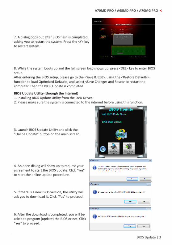
7. A dialog pops out after BIOS flash is completed, asking you to restart the system. Press the <Y> key to restart system.
8. While the system boots up and the full screen logo shows up, press <DEL> key to enter BIOS setup.After entering the BIOS setup, please go to the <Save & Exit>, using the <Restore Defaults> function to load Optimized Defaults, and select <Save Changes and Reset> to restart the computer. Then the BIOS Update is completed.
BIOS Update Utility (through the Internet)1. Installing BIOS Update Utility from the DVD Driver. 2. Please make sure the system is connected to the internet before using this function.
3. Launch BIOS Update Utility and click the “Online Update” button on the main screen.
4. An open dialog will show up to request your agreement to start the BIOS update. Click “Yes” to start the online update procedure.
5. If there is a new BIOS version, the utility will ask you to download it. Click “Yes” to proceed.
6. After the download is completed, you will be asked to program (update) the BIOS or not. Click “Yes” to proceed.

4 | BIOS Update
7. After the updating process is finished, you will be asked you to reboot the system. Click “OK” to reboot.
8. While the system boots up and the full screen logo shows up, press <DEL> key to enter BIOS setup.After entering the BIOS setup, please go to the <Save & Exit>, using the <Restore Defaults> function to load Optimized Defaults, and select <Save Changes> and <Reset> to restart the computer. Then, the BIOS Update is completed.
BIOS Update Utility (through a BIOS file)1. Installing BIOS Update Utility from the DVD Driver.2. Download the proper BIOS from http://www.biostar.com.tw/
3. Launch BIOS Update Utility and click the “Update BIOS” button on the main screen.
4. A warning message will show up to request your agreement to start the BIOS update. Click “OK” to start the update procedure.
5. Choose the location for your BIOS file in the system. Please select the proper BIOS file, and then click on “Open”. It will take several minutes, please be patient.

UEFI BIOS Setup | 5
A70MD PRO / A68MD PRO / A70MG PRO
6. After the BIOS Update process is finished, click on “OK” to reboot the system.
7. While the system boots up and the full screen logo shows up, press <DEL> key to enter BIOS setup.After entering the BIOS setup, please go to the <Save & Exit>, using the <Restore Defaults> function to load Optimized Defaults, and select <Save Changes and Reset> to restart the computer. Then, the BIOS Update is completed.
Backup BIOSClick the Backup BIOS button on the main screen for the backup of BIOS, and select a proper location for your backup BIOS file in the system, and click “Save”.
6 | UEFI BIOS Setup
UEFI BIOS Setup
IntroductionThe purpose of this manual is to describe the settings in the AMI UEFI BIOS Setup program on this motherboard. The Setup program allows users to modify the basic system configuration and save these settings to NVRAM.UEFI BIOS determines what a computer can do without accessing programs from a disk. This system controls most of the input and output devices such as keyboard, mouse, serial ports and disk drives. BIOS activates at the first stage of the booting process, loading and executing the operating system. Some additional features, such as virus and password protection or chipset fine-tuning options are also included in UEFI BIOS. The rest of this manual will to guide you through the options and settings in UEFI BIOS Setup.
Plug and Play SupportThis AMI UEFI BIOS supports the Plug and Play Version 1.0A specification.
EPA Green PC SupportThis AMI UEFI BIOS supports Version 1.03 of the EPA Green PC specification.
ACPI SupportAMI ACPI UEFI BIOS support Version 1.0/2.0 of Advanced Configuration and Power interface specification (ACPI). It provides ASL code for power management and device configuration capabilities as defined in the ACPI specification, developed by Microsoft, Intel and Toshiba.
PCI Bus SupportThis AMI UEFI BIOS also supports Version 2.3 of the Intel PCI (Peripheral Component Interconnect) local bus specification.
DRAM SupportDDR3 SDRAM (Double Data Rate III Synchronous DRAM) is supported.
Using SetupWhen starting up the computer, press <Del> during the Power-On Self-Test (POST) to enter the UEFI BIOS setup utility.In the UEFI BIOS setup utility, you will see General Help description at the top right corner, and this is providing a brief description of the selected item. Navigation Keys for that particular menu are at the bottom right corner, and you can use these keys to select item and change the settings.
NoticeThe default UEFI BIOS settings apply for most conditions to ensure optimum performance of the »motherboard. If the system becomes unstable after changing any settings, please load the default settings to ensure system’s compatibility and stability. Use Load Setup Default under the Exit Menu.For better system performance, the UEFI BIOS firmware is being continuously updated. The UEFI BIOS »information described in this manual is for your reference only. The actual UEFI BIOS information and settings on board may be slightly different from this manual.The content of this manual is subject to be changed without notice. We will not be responsible for any »mistakes found in this user’s manual and any system damage that may be caused by wrong-settings.

1 Main Menu | 7
A70MD PRO / A68MD PRO / A70MG PRO
1 Main Menu
Once you enter AMI UEFI BIOS Setup Utility, the Main Menu will appear on the screen providing an overview of the basic system information.
BIOS InformationIt shows system information including UEFI BIOS version, Project Code, Model Name, Build Date and etc.
Total MemoryShows system memory size, VGA shard memory will be excluded.
System LanguageChoose the system default language.
System DateSet the system date. Note that the ‘Day’ automatically changes when you set the date.
System TimeSet the system internal clock.

8 | 2 Advanced Menu
2 Advanced Menu
The Advanced Menu allows you to configure the settings of CPU, Super I/O, Power Management, and other system devices.
NoticeBeware of that setting inappropriate values in items of this menu may cause system to malfunction. »
PCI Subsystem Settings
PCI Latency TimerThis item sets the value to be programmed into PCI Latency Timer Register.Options: 32 PCI Bus Clocks (Default) / 64 PCI Bus Clocks / 96 PCI Bus Clocks / 128 PCI Bus Clocks / 160 PCI Bus Clocks / 192 PCI Bus Clocks / 224 PCI Bus Clocks / 248 PCI Bus Clocks

2 Advanced Menu | 9
A70MD PRO / A68MD PRO / A70MG PRO
VGA Palette SnoopThis item enables or disables VGA Palette Registers Snooping.Options: Disabled (Default) / Enabled
PCI Express Settings
No SnoopThis item enables or disables PCI Express Device No Snoop option.Options: Enabled (Default) / DisabledMaximum PayloadThis item sets Maximum Payload of PCI Express Device or allows System BIOS to select the value.Options: Auto (Default) / 128 Bytes / 256 Bytes / 512 Bytes / 1024 Bytes / 2048 Bytes / 4096 BytesMaximum Read RequestThis item sets Maximum Read Request Size of PCI Express Device or allows System BIOS to select the value.Options: Auto (Default) / 128 Bytes / 256 Bytes / 512 Bytes / 1024 Bytes / 2048 Bytes / 4096 BytesASPM SupportThis item sets the ASPM Level: Force LO – Force all links to LO State; Auto – BIOS auto configures; Disabled – Disables ASPM.Options: Disabled (Default) / Auto / Force L0sRestore PCIE RegistersOn non-PCI Express aware OS’s (Pre Windows Vista) some devices may not be correctly reinitialized after S3. Enabling this restores PCI Express device configurations on S3 resume. Warning: Enabling this cause issues with other hardware after resume.Options: Disabled (Default) / Enabled

10 | 2 Advanced Menu
ACPI Settings/ WakeUp Event control
EuP ControlWhen EuP is enabled, the system will meet EuP requirement. All wake up events do not work except Power Button after power down system (S5).Options: Disabled (Default) / EnabledACPI Sleep StateThis item selects the highest ACPI sleep state the system will enter when the SUSPEND button is pressed.Options: S3 only (Suspend to RAM) (Default) / Suspend DisabledPME Wake up from S5The item enables the system to wake from S5 using PME event.Options: Disabled (Default) / EnabledWake system with Fixed TimeThis item enables or disables the system to wake on by alarm event. When this item is enabled, the system will wake on the hr::min::sec specified.Options: Disabled (Default) / EnabledWake up dateYou can choose which date the system will boot up.Wake up hour / Wake up minute / Wake up secondYou can choose the system boot up time, input hour, minute and second to specify.PS2 Keyboard PowerOnThis item allows you to control the keyboard power on function.Options: Disabled (Default) / Any Key / Stroke Key / Specific KeyStroke KeysThis item will show only when Keyboard PowerOn is set “Stroke Key.”Options: Wake Key (Default) / Power Key / Ctrl+F1 / Ctrl+F2 / Ctrl+F3 / Ctrl +F4 / Ctrl+F5 / Ctrl+F6Specific KeyThis item will show only when Keyboard PowerOn is set “Specific Key.” Press Enter to set Specific key.

2 Advanced Menu | 11
A70MD PRO / A68MD PRO / A70MG PRO
PS2 Mouse PowerOnThis item allows you to control the mouse power on function.Options: Disabled (Default) / EnabledUSB Device Wakeup from S3/S4This item allows you to enable or disabled the USB resume from S3/S4 function.Options: Disabled (Default) / Enabled
CPU ConfigurationThis item shows CPU Information
Power NowThis item allows you to enable or disable the PowerNow power saving technology.Options: Enabled (Default) / Disabled
NX ModeThis item allows you to enable or disable No-execute page protection FunctionOptions: Enabled (Default) / Disabled
SVMThis item allows you to enable AMD virtualization in CPU.Options: Enabled (Default) / Disabled
CPB ModeThis item allows you to enable or disable CPB.Options: Auto (Default) / Disabled
C6 ModeThis item allows you to enable or disable C6.Options: Enabled (Default) / Disabled
Core LevelingChange the number of compute unit in the systemOptions: Auto (Default) / Single Core / Dual Core
12 | 2 Advanced Menu
HTC temperature limitThis item allows you to set HTC temperature limit. Range: 70 °C - 85 °COptions: 70 °C(Default)
Configurable TDP (This item will appear only when using FM2+ CPU.)This item allows you to enable or disable cTDP by CPU.Options: Disabled (Default) / Enabled
Note: The following items appear only when you set the Configurable TDP item to [Enabled] »
Configurable TDP Value (W)This item allows you to input configurable TDP Value (45-65).Options: 45 (Default)
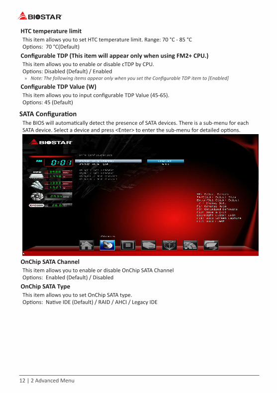
SATA ConfigurationThe BIOS will automatically detect the presence of SATA devices. There is a sub-menu for each SATA device. Select a device and press <Enter> to enter the sub-menu for detailed options.
OnChip SATA ChannelThis item allows you to enable or disable OnChip SATA ChannelOptions: Enabled (Default) / Disabled
OnChip SATA TypeThis item allows you to set OnChip SATA type.Options: Native IDE (Default) / RAID / AHCI / Legacy IDE

2 Advanced Menu | 13
A70MD PRO / A68MD PRO / A70MG PRO
USB Configuration
Legacy USB SupportThe item allows you to enable Legacy USB support. AUTO option disables legacy support if no USB devices are connected. DISABLE option will keep USB devices available only for EFI applications.Options: Enabled (Default) / Disabled / Auto
Legacy USB3.0 SupportThe item allows you to enable or disable Legacy USB3.0 (XHCI) Controller support.Options: Enabled (Default) / Disabled
XHCI Hand-OffThis is a workaround for OSes without XHCI hand-off support. The XHCI ownership change should be claimed by XHCI driver.Options: Enabled (Default) / Disabled
EHCI Hand-OffThis is a workaround for OSes without EHCI hand-off support. The EHCI ownership change should be claimed by EHCI driver.Options: Disabled (Default) / Enabled
Mass Storage DevicesMass storage device emulation type. ‘Auto’ enumerates devices according to their media format. Optical drives are emulated as ‘CDROM’, drivers with no media will be emulated according to a driver type.Options: Auto (Default) / Floppy / Forced FDD / Hard Disk / CR-ROM

14 | 2 Advanced Menu
Smart Fan Control
CPU Smart FanThis item allows you to control the CPU Smart Fan function.Options: Disabled (Default) / 4Pin
CPU Fan CalibratePress [ENTER] to calibrate CPU Fan.
Control ModeThis item provides several operation modes of the fan.Options: Quiet / Aggressive / Manual
Fan Ctrl OFF(°C)When CPU temperature is lower than this value, the CPU fan will keep lowest RPM.Options: 10 (°C) (default)
Fan Ctrl On( °C)When CPU temperature is higher than this value, the CPU fan controller will turn on.Options: 20 (°C) (Default)
Fan Ctrl Start ValueThis item sets CPU FAN Start Speed Value.Options: 50 (Default)
Fan Ctrl SensitiveThe bigger the numeral is, the higher the FAN speed is.Options: 30 (Default)

2 Advanced Menu | 15
A70MD PRO / A68MD PRO / A70MG PRO
Super IO Configuration
Restore AC Power LossThis setting specifies how your system should behave after a power fail or interrupts occurs. Power Off: Leaving the system in power-off status after power recovers. Power ON: Powering on the system immediately when power returns. Last State: 1. Leaving the system in power-off if the system shuts down at DC off status; 2. Powering on the system immediately if the system shuts down at DC on status.Options: Power Off (Default) / Power On / Last State
Serial Port 1 Configuration
Serial PortThis item enables or disables Serial Port (COM).Options: Enabled (Default) / Disabled

16 | 2 Advanced Menu
Change SettingsThis item selects an optimal setting for Super IO device.Options: Auto (Default) / IO=3F8h; IRQ=4 / IO=3F8h; IRQ=3, 4, 5, 6, 7, 10, 11, 12 / IO=2F8h; IRQ=3, 4, 5, 6, 7, 10, 11, 12 / IO=3E8h; IRQ=3, 4, 5, 6, 7, 10, 11, 12 / IO=2E8h; IRQ=3, 4, 5, 6, 7, 10, 11, 12
H/W Monitor
PWM Processor HotThis item enables or disables PWM Processor Hot.Options: Enabled (Default) / Disabled
Shutdown TemperatureThis item allows you to set up the CPU shutdown Temperature. Options: Disabled (Default) / 70°C/158°F / 75°C/167°F / 80°C/176°F

3 Chipset Menu | 17
A70MD PRO / A68MD PRO / A70MG PRO
Network Stack
Network StackThis item enables or disables UEFI network stackOptions: Disabled (Default) / Enabled
Note: The following items appear only when you set the Network Stack item to [Enabled] »
IPv4 PXE SupportThis item enables or disables IPv4 PXE Boot Support. If disabled IPv4 booth option will not be created.Options: Enabled (Default) / Disabled
IPv6 PXE SupportThis item enables or disables IPv6 PXE Boot Support. If disabled IPv6 booth option will not be created.Options: Enabled (Default) / Disabled
PXE boot wait timeWait time to press ESC key to abort the PXE boot.
Media detect timeWait time in sec to detect media.

18 | 3 Chipset Menu
3 Chipset Menu
This section describes configuring the PCI bus system. PCI, or Personal Computer Interconnect, is a system which allows I/O devices to operate at speeds nearing the speed of the CPU itself uses when communicating with its own special components.
Notice: Beware of that setting inappropriate values in items of this menu may cause system to »malfunction.
South Bridge

3 Chipset Menu | 19
A70MD PRO / A68MD PRO / A70MG PRO
SB USB Configuration
XHCI ControllerThis item allows you to enable XHCI controller.Options: Enabled (Default) / DisabledOHCI HC (Bus 0 Dev 18/19 Fn 0)This item allows you to control OHCI host controller. (USB 1.1 Device)Options: Enabled (Default) / DisabledEHCI HC (Bus 0 Dev 18/19 Fn 2)This item allows you to control EHCI host controller. (USB 2.0 Device)Options: Enabled (Default) / Disable
Note: OHCI HC (Bus 0 Dev 22 Fn 0) and EHCI HC (Bus 0 Dev 22 Fn 2) items will appear, when you set the »XHCI Controller item to disabled.
SB GPP Port Configuration

20 | 3 Chipset Menu
GPP Link ASPMOptions: Disabled (Default) / L0s / L1 / L0s + L1GPP Gen2/ UMI Gen2Options: Enabled (Default) / DisabledSB Azalia Audio Configuration
HD Audio Azalia DeviceThis item allows you to control the HD audio device.Options: Enabled (Default) / Auto / Disabled
North Bridge
IOMMUIt enables or disables IOMMU support.Options: Disabled (Default) / Enabled

3 Chipset Menu | 21
A70MD PRO / A68MD PRO / A70MG PRO
GFX Configuration
Primary Video DeviceThis item allows you to select Primary Video Device that BIOS will use to for output.Options: NB PCIe slot Video (Default) / IGD VideoIntegrated GraphicsThis item set integrated graphics controller.Options: Auto (Default) / Disabled / Force
Note: The following items appear only when you set the Integrated Graphics item to [Force] »UMA Frame Buffer Size: 32M / 64M / 128 M / 256 M / 512M / 1G / 2G
DVI PortThis item allows you to set DVI Port.Options: Dual Link DVI (Default) / HDMI
Note: The item is only for A70MD PRO/A68MD PRO. »GFX HD Audio ControllerThis item allows you to set GFX HD Audio controller.Options: Enabled (Default) / DisabledPSPP PolicyThis item allows you to set PCIe speed power policy.Options: Balanced-High (Default) / Disabled / Performance / Balanced-Low / Power SavingSurround ViewThis item supports multi-display function.Options: Disabled (Default) / EnabledFB LocationThis item allows you to set FB LocationOptions: Above 4G (Default) / Below 4G

22 | 3 Chipset Menu
Onboard Devices
Realtek PCIE NICThis item enables/disables Realtek PCIE NICOptions: Enabled (Default) / DisabledOnboard LAN Option ROMThis item enables/disables Onboard LAN Option ROMOptions: Disabled (Default) / Enabled

4 Boot Menu | 23
A70MD PRO / A68MD PRO / A70MG PRO
4 Boot Menu
This menu allows you to setup the system boot options.
Setup Prompt TimeoutThis item sets number of seconds to wait for setup activation key.Options: 2 (Default)
Bootup NumLock StateThis item selects the keyboard NumLock state.Options: On (Default) / Off
Full Screen Logo DisplayThis item allows you to enable/disable Full Screen Logo Show function.Options: Enabled (Default) / Disabled
Fast BootThis item allows you to enable/disable boot with initialization of a minimal set of devices required to launch active boot option. Has no effect for BBS boot options.Options: Disabled (Default) / Enabled
Note: The following items appear only when you set the Fast Boot function to [Enabled] »
SATA SupportOptions: Last Boot HDD Only (Default) / All SATA Devices
VGA SupportIf Auto, only install Legacy OpRom with Legacy OS and logo would NOT be shown during post. EFI driver will still installed with EFI.Options: EFI Driver (Default) / Auto

24 | 4 Boot Menu
USB SupportIf Disabled, all USB devices will NOT be available until after OS boot. If Partial Initial, specific USB port/device will NOT be available before OS boot. If Enabled, all USB devices will be available in OS and Post.Options: Full Initial (Default) / Partial Initial / Disabled
PS2 Devices SupportIf Disabled, PS2 devices will be skipped.Options: Enabled (Default) / Disabled
Network Stack Driver SupportIf Disabled, Network Stack Drivers will be skipped.Options: Disabled (Default) / Enabled
BIOS Flash protectionWhile enabled, it can’t flash write and flash erase by SMI.Options: Enabled (Default) / Disabled
Boot Success BeepWhen this item is set to Enabled, BIOS will let user know boot success with beep.Options: Enabled (Default) / Disabled
Boot Option #1/#2/#3The items specify the boot device priority sequence from the available devices. The number of device items that appears on the screen depends on the number of devices installed in the system.
CD/DVD ROM Drive BBS PrioritiesThis item sets the order of the legacy devices in this group.
Hard Drive BBS PrioritiesThis item sets the order of the legacy devices in this group.

4 Boot Menu | 25
A70MD PRO / A68MD PRO / A70MG PRO
CSM16 parameters
GateA20 ActiveUpon Request – FA20 can be disabled using BIOS services. Always – do not allow disabling GA20; this option is useful when any RT code is executed above 1MBOptions: Upon Request (Default) / Always
Option ROM MessagesThis item sets the display mode for option ROM.Options: Force BIOS (Default) / Keep Current
INT19 Trap ResponseBIOS reaction on INT19 trapping by Option ROM: IMMEDIATE – execute the trap right away; POSTPONED – execute the trap during legacy boot.Options: Postponed (Default) / Immediate

26 | 5 Security Menu
CSM parameters
Launch CSMThis option controls if CSM will be launched.Options: Enabled (Default) / Disabled
Boot option filterThis option controls what devices system can boot to.Options: UEFI and Legacy (Default) / Legacy only / UEFI only
Launch PXE OpROM policyThis item controls the execution of UEFI and Legacy PXE OpROMOptions: Legacy only (Default) / UEFI only / Do not launch
Launch Storage OpROM policyThis item controls the execution of UEFI and Legacy Storage OpROMOptions: Legacy only (Default) / UEFI only / Do not launch
Launch Video OpROM policyThis item controls the execution of UEFI and Legacy Video OpROMOptions: Legacy only (Default) / UEFI only / Do not launch
Other PCI device ROM priorityFor PCI devices other than Network, Mass storage or Video defines which OpROM to launchOptions: Legacy OpROM (Default) / UEFI OpROM

5 Security Menu | 27
A70MD PRO / A68MD PRO / A70MG PRO
5 Security Menu
Administrator PasswordThis item sets Administrator Password.
User PasswordThis item sets User Password.
Secure Boot Menu

28 | 5 Security Menu
Secure Boot ControlSecure Boot flow control. Secure Boot can be enabled only when 1. Platform Key (PK) is enrolled and Platform is operating in user mode and 2.CSM function is disabled in Setup.Options: Disabled (Default) / Enabled Note: The following items appear only when you set the Secure Boot Control function to [Enabled]
Key Management
Enroll All Factory Default KeysIt allows you to immediately load/clear the default Security Boot keys, Platform key (PK), Key-exchange Key (KEK), Signature database (db), and Revoked Signatures (dbx). The Platform Key (PK) state will change from Unloaded mode to Loaded mode. The settings are applied after reboot or at the next reboot.Platform Key (PK)Delete PK – Allows you to delete the PK file from your system.Set new PK – Allows you set new PK file.Key Exchange Key Database (KEK)Delete KEK – Allows you to delete the KEK file from your system.Set new KEK – Allows you set new KEK file.Append Var to KEK – Allows you append Var to KEK.Authorized Signature Database (DB)Delete DB – Allows you to delete the DB file from your system.Set new DB – Allows you set new DB file.Append Var to DB – Allows you append Var to DB.Authorized Timestamps Database (DBT)Delete DBT – Allows you to delete the DBT file from your system.Set new DBT – Allows you set new DBT file.Append Var to DBT – Allows you append Var to DBT.Forbidden Signature Database (DBX)Delete DBX – Allows you to delete the DBX file from your system.Set new DBX – Allows you set new DBK file.Append Var to DBX – Allows you append Var to DBX.

6 Performance Menu | 29
A70MD PRO / A68MD PRO / A70MG PRO
6 Performance Menu
This submenu allows you to change voltage and clock of various devices.(However, we suggest you use the default setting. Changing the voltage and clock improperly may damage the device.)
NoticeThe options and default settings might be different by RAM or CPU models. »Beware of that setting inappropriate values in items of this menu may cause system to malfunction. »- Values in Red: Danger- Values in Yellow: Warning- Values in White: Normal
CPU ClockThis item allows user to adjust CPU clockRange: 100MHz-128Mhz
IGD Clock ControlThis item allows user to adjust IGD clockOptions: Auto (Default) / Enabled
Note: The following items appear only when you set the IGD Clock Control item to [Enabled] »
IGD ClockAllow BIOS to Select IGD clock, Range 300MHz-2000MHz
Memory Clock ModeThis item allows user to select the DRAM Frequency programming method. If Auto, the DRAM speed will be based on SPDs. If Manual, the DRAM speed specified will be programmed regardless of SPD. If AMP/XMP/XMP2, the DRAM speed specified will be refer memory profile.Options: Auto (Default) / Manual / AMP / XMP1 / XMP2
Note: The following items appear only when you set the Memory Clock Mode item to [Manual] »Memory Frequency: DDR 800 / DDR3 1066 / DDR3 1333 / DDR3 1600 / DDR3 1866 / DDR3 2133 / DDR3 2400

30 | 6 Performance Menu
AMD Pstate Configuration
Custom P-StatedThis item will tell BIOS whether to use the step option below this configure the P-State, or whether to configure the P-States automatically.Options: Disabled (Default) / Enabled
Note: The following items appear only when you set the Custom P-State item to [Enabled] »Core FIDThis item sets the frequency to use for Core P-State selected. Value is saved in the _PSS object.Options: x16 1600MHz ~ x63 6300MHzCore VIDThis function allows you to adjust the voltage of Core.Core DIDThis is the Core Divider.Options: Divided by 1 (Default) / Divided by 2 / Divided by 4 / Divided by 8 / Divided by 16
Custom NB P-StatedThe item tells BIOS whether to use the setup options below this to configure the NB P-States, or whether to configure the NB P-states automatically.Options: Disabled (Default) / Enabled
Note: The following items appear only when you set the Custom NB P-State item to [Enabled] »NB FIDThis item sets the frequency to use for Core P-State selected. Value is saved in the _PSS object.Options: 400MHz ~ 1600MHz

6 Performance Menu | 31
A70MD PRO / A68MD PRO / A70MG PRO
DRAM Timing Configuration
2TCMDOptions: Auto (Default) / 1T / 2TCLOptions: Auto (Default) / 5~16 CLKTRCDOptions: Auto (Default) / 2~19 CLKTRPOptions: Auto (Default) / 5~19 CLKTRASOptions: Auto (Default) / 8~42 CLKTRCOptions: Auto (Default) / 10~58 CLKTRFCOptions: Auto (Default) / 90ns / 110ns / 160ns / 300ns / 350nsTWROptions: Auto (Default) / 5~8 / 10 / 12 / 14 / 16 CLKTWTROptions: Auto (Default) / 4~11 CLKTRRDOptions: Auto (Default) / 1~9 CLKTRTPOptions: Auto (Default) / 4~11 CLK
DDR Memory VoltageThis item allows you to select DDR Memory Voltage Control.
PWM Core Load Line ControlThis item allows you to set PWM Core Load Line ControlOptions: 0% (Default) / Disabled / -40% / -20% / +20% / +40% / +60% / +80%

32 | 6 Performance Menu
PWM NB Load Line ControlThis item allows you to set PWM NB Load Line ControlOptions: 0% (Default) / Disabled / -40% / -20% / +20% / +40% / +60% / +80%
BIOSTAR Memory Insight
DDR3_A1/B1These items display SPD information of DDR3 memory.

7 Exit Menu | 33
A70MD PRO / A68MD PRO / A70MG PRO
7 Exit Menu
This menu allows you to load the optimal default settings, and save or discard the changes to the BIOS items.
Discard Changes and ExitAbandon all changes made during the current session and exit setup.
Save Changes and ResetReset the system after saving the changes.
Restore DefaultsThis selection allows you to reload the BIOS when problem occurs during system booting sequence. These configurations are factory settings optimized for this system.
Launch Shell from deviceThis item attempts to EFI Shell application (Shellx64.efi) from one of the available devices.