biomedical nanobubbles and opportunities for microfluidics
TRANSCRIPT

RSC Advances
REVIEW
Ope
n A
cces
s A
rtic
le. P
ublis
hed
on 0
5 O
ctob
er 2
021.
Dow
nloa
ded
on 1
/17/
2022
2:1
5:38
PM
. T
his
artic
le is
lice
nsed
und
er a
Cre
ativ
e C
omm
ons
Attr
ibut
ion-
Non
Com
mer
cial
3.0
Unp
orte
d L
icen
ce.
View Article OnlineView Journal | View Issue
Biomedical nano
aDepartment of Mechanical and Industria
Victoria Street, Toronto, Ontario M5B 2K3,bInstitute for Biomedical Engineering, Scienc
Between Ryerson University and St. Michae
Ontario M5B 1T8, CanadacKeenan Research Centre for Biomedical Sci
Street, Toronto, Ontario M5B 1W8, CanadadDepartment of Physics, Ryerson University,eDepartment of Electrical, Computer, and Bio
350 Victoria Street, Toronto, Ontario M5B 2fGraduate Program in Biomedical Engineerin
Toronto, Ontario M5B 2K3, Canada
Cite this: RSC Adv., 2021, 11, 32750
Received 24th June 2021Accepted 19th September 2021
DOI: 10.1039/d1ra04890b
rsc.li/rsc-advances
32750 | RSC Adv., 2021, 11, 32750–3
bubbles and opportunities formicrofluidics
Ali A. Paknahad,abc Liam Kerr,abc Daniel A. Wong, bce Michael C. Kolios bcd
and Scott S. H. Tsai *abcf
The use of bulk nanobubbles in biomedicine is increasing in recent years, which is attributable to the array of
therapeutic and diagnostic tools promised by developing bulk nanobubble technologies. From cancer drug
delivery and ultrasound contrast enhancement to malaria detection and the diagnosis of acute donor tissue
rejection, the potential applications of bulk nanobubbles are broad and diverse. Developing these
technologies to the point of clinical use may significantly impact the quality of patient care. This review
compiles and summarizes a representative collection of the current applications, fabrication techniques,
and characterization methods of bulk nanobubbles in biomedicine. Current state-of-the-art generation
methods are not designed to create nanobubbles of high concentration and low polydispersity, both
characteristics of which are important for several bulk nanobubble applications. To date, microfluidics
has not been widely considered as a tool for generating nanobubbles, even though the small-scale
precision and real-time control offered by microfluidics may overcome the challenges mentioned above.
We suggest possible uses of microfluidics for improving the quality of bulk nanobubble populations and
propose ways of leveraging existing microfluidic technologies, such as organ-on-a-chip platforms, to
expand the experimental toolbox of researchers working to develop biomedical nanobubbles.
1. Introduction
Nanobubbles are nanoscopic bubbles whose research hasgained popularity over the last decade as many industries arebeginning to recognize the potential applications of nanobubblesin various elds.1–3 Nanobubbles exhibit several characteristicphysical properties: excellent stability, high internal pressure, andhigh surface-to-volume ratio, opening new pathways for researchin various elds of advanced science and technology.4
Nanobubbles can fall under two broad categories: surfacenanobubbles and bulk nanobubbles. The term surface nano-bubbles is used to characterize gas-lled hemispherical capsthat form on solid surfaces with a height within the range of 10–100 nm, and a radius within the range of 50–500 nm.4 Bulknanobubbles are described as gas-lled spherical bubbles
l Engineering, Ryerson University, 350
Canada. E-mail: [email protected]
e and Technology (iBEST), A Partnership
l's Hospital, 209 Victoria Street, Toronto,
ence, Unity Health Toronto, 209 Victoria
Toronto, Ontario M5B 2K3, Canada
medical Engineering, Ryerson University,
K3, Canada
g, Ryerson University, 350 Victoria Street,
2774
found in liquid suspension that have a diameter less than1000 nm, and are subjected to Brownian motion.4,5 Our reviewfocuses on bulk nanobubbles, detailing their characterization,production and applications in biomedicine. We also attempt toprovide insights and guidance for future microuidics researchin this emerging eld.
Historically, the earliest evidence of bulk nanobubbles isfrom a 1981 report by Johnson and Cooke.1 They describe theproduction of submicron gas-lled bubbles due to shear stressin seawater. The authors also found that the bulk nanobubblesexhibit stability for prolonged periods (>22 h).1 Since then, therehave been many questions that challenge the stability and theexistence of bulk nanobubbles post-production. Some of thereluctance to accept the existence of stable bulk nanobubblesstems from predictions of theoretical models that predicta vanishingly short lifetime for nanobubbles. A primary factorconsidered is based on the capillarity model of Young andLaplace, which states that the pressure inside a bubble isgreater than the pressure outside the bubble by an amountdictated by the gas–liquid surface tension and the bubbleradius, a phenomenon known as Laplace pressure,6
DPLaplace ¼ PInside � POutside ¼ 2g
r; (1)
where PInside and POutside are the pressure inside and outside ofthe bubble, respectively. Also, g is the gas–liquid surfacetension, and r is the bubble radius. For sub-micron bubbles,
© 2021 The Author(s). Published by the Royal Society of Chemistry

Review RSC Advances
Ope
n A
cces
s A
rtic
le. P
ublis
hed
on 0
5 O
ctob
er 2
021.
Dow
nloa
ded
on 1
/17/
2022
2:1
5:38
PM
. T
his
artic
le is
lice
nsed
und
er a
Cre
ativ
e C
omm
ons
Attr
ibut
ion-
Non
Com
mer
cial
3.0
Unp
orte
d L
icen
ce.
View Article Online
such as bulk nanobubbles, where the radius is in the nanometerrange, the pressure inside the bubble is predicted to be veryhigh. From here, Henry's law for the solubility of a gas in anaqueous phase is used to explain the destabilization of thebubble in response to the large pressure gradient across thebubble shell. As a result, bubbles can either (a) increase in sizeby inward diffusion of gas from the surrounding and then beremoved from solution by buoyant forces, or (b) they can shrinkthrough outward diffusion, eventually disappearing once all thegas molecules have been removed from the bubble.7
Epstein and Plesset, pioneers in understanding bubblegrowth and dissolution, observed this phenomenon anddeveloped a mathematical model for the diffusion processaround a bubble in which they state, “a gas bubble in a liquid–gas solution will grow or shrink by diffusion accordingly as thesolution is oversaturated or undersaturated.”8 They estimate thetime-dependent bubble radius,
rðtÞzffiffiffiffiffiffiffiffiffiffiffiffiffiffiffiffiffiffiffiro2 þ 2at
p; (2)
where, ro is the initial bubble radius, t is time, and a is a positive
constant given by,DðCi � CsÞ
r. D is the diffusion coefficient of
the gas at the liquid interface, Cs is the concentration of dis-solved gas immediately adjacent to the bubble, Ci is the initialconcentration of dissolved gas in solution, and r is the densityof the gas within the bubble.8 The theory suggests that bubblessuspended in a gas-saturated solution rapidly shrink andvanish, as shown by Alheshibri et al. in Fig. 1.9 Epstein andPlesset's theory predicts that a bubble whose diameter is less than1000 nm has a lifetime that is less than 0.02 s, a time too short tobe measured or detected.9 Despite these theoretical predictions,experimental evidence over the last decade, particularly thenotable works by Nirmalkar et al., have demonstrated the existenceand stability of bulk nanobubbles.9–13 We note that this review isnot focused on the debate regarding the existence and stability ofbulk nanobubbles, and readers are encouraged to read the work ofAlhesibri et al. titled “A History of Nanobubbles” for an extensivedescription of the subject of bulk nanobubble stability.9
Briey, several theories attempt to explain the unexpectedstability of bulk nanobubbles. One explanation is that
Fig. 1 Lifetime of a bubble smaller than 1000 nm predicted by thetheory of Epstein and Plesset. The graph depicts the calculated radiusof a nitrogen-filled bubble in a nitrogen saturated solution versus time(T ¼ 300 K, g ¼ 0.072 J m�2, D ¼ 2.0 � 10�9 m2 s�1, Csat ¼ 0.6379 molm�3, r1 atm ¼ 40.6921 mol m�3).8,9
© 2021 The Author(s). Published by the Royal Society of Chemistry
nanobubble stability is attributed to their low rising velocity,which is almost negligible due to their strong Brownian effect,and a low level of buoyancy.9 This prevents nanobubbles fromrising to the free surface where the change in pressure of theatmosphere can cause a shi in the equilibrium between thepressure on the inside of the bubble and the pressure on theoutside of the bubble, thereby causing the bubble to becomeunstable and burst.9,11,14,15
Other explanations involve the physical chemistry of thenanobubbles. The electrically charged interface of the bubblecreates strong repulsive forces between bubbles, which preventbubble coalescence, bubble bursting, and Ostwald ripening.Others speculate that the bulk nanobubble stability is a result ofthe presence of “universal” contaminants.9–11,14 The contami-nants are organic or surfactant molecules that form a shellaround the nanobubbles, that reduces interfacial tension,thereby decreasing the Laplace pressure within the bubble, andpreventing dissolution.14,16–20 Despite all of these explanations,to date, the literature has not converged on a single theory thatexplains the apparent stability of bulk nanobubbles, but bulknanobubble technology has nevertheless continued to progress,leading to new applications. Applications of bulk nanobubblesare in the food, water and cleaning industries.4,21–24 Bulknanobubbles are also useful in several biomedical applications.The benets of nanobubbles in biomedical applications arerelated to their biocompatibility, customizability, stability, andsmall size.
Several production techniques have been employed toproduce bulk nanobubbles using mechanical and chemicalproduction methods. However, many of these methodsgenerate highly polydisperse bubble populations and lackcontrollability over size and concentration. Furthermore, someof these production systems use reagents inefficiently, leadingto excessive waste of costly experimental materials. In thisreview, we suggest the utilization of microuidics and proposepossible microuidic implementation methods to addresssome of the current challenges in making bulk nanobubbles.
2. Biomedical applications2.1 Biomedical imaging
2.1.1 Ultrasound contrast enhancement. One of the mostreported biomedical applications of bulk nanobubbles isultrasound image contrast enhancement. Gas bubbles withintissues can act as harmonic oscillators and oscillate/resonate inresponse to ultrasound excitation due to the compressibility ofthe encapsulated gas.25 The second harmonic increases theintensity of backscattered ultrasound signals, which results ingreater signal intensity in tissues with bubbles present than inbackground tissue.26–30 Researchers and clinicians have beenusing microbubbles to achieve this ultrasound intensityenhancement effect in blood pool imaging for decades;however, nano-scale contrast agents offer unique benets whichcannot be achieved using micro-scale agents.31–34 Namely, nano-scale agents are small enough to extravasate from the leakytumour vasculature as a result of the improved permeability andretention effect (EPR).35,36
RSC Adv., 2021, 11, 32750–32774 | 32751
RSC Advances Review
Ope
n A
cces
s A
rtic
le. P
ublis
hed
on 0
5 O
ctob
er 2
021.
Dow
nloa
ded
on 1
/17/
2022
2:1
5:38
PM
. T
his
artic
le is
lice
nsed
und
er a
Cre
ativ
e C
omm
ons
Attr
ibut
ion-
Non
Com
mer
cial
3.0
Unp
orte
d L
icen
ce.
View Article Online
Extravasation via the EPR effect is unique to nano-scaleagents. Extravasation of the contrast agent affords cliniciansinsight into the tissue of interest and allows functionalizedbubbles to target surface markers of tumour cells.36,37 There isalso evidence that nanobubbles produce a similar qualityultrasound image compared to microbubbles despite the lowerbackscatter intensity per bubble.38,39 Perera et al. have con-ducted research to improve the stability and extravasationability of bulk nanobubbles for ultrasound contrast enhance-ment.40 In 2010, they showed that incorporating Pluronicsurfactants into the lipid shell before adding the gas core waseffective at yielding sub-micron bubbles without reducingechogenicity or stability.32 In more recent work, they demon-strate that incorporating crosslinkedN,N-diethylacrylamide andN,N-bis(acryoyl) cystamine networks into the lipid shell of thePluronic nanobubbles increases ultrasound signal intensity andreduces the decay rate of nanobubbles both in vitro and in vivo.40
2.1.2 Photoacoustic contrast enhancement. Photoacousticimaging can also benet from the unique physical character-istics of nanobubbles. Photoacoustic imaging techniques usethe photoacoustic effect to generate an image of the targettissue. To use this effect clinically, short wave light pulses areused to excite chromophores, optically absorptive molecules intissue which create tissue thermoelastic expansion. The result-ing pressure wave is sensed by an ultrasound transducer, whichobtains the spatial distribution of the chromophores.39,41–44
Chromophores can be encapsulated within microbubblesand nanobubbles, which increases their circulation half-life,and reduces the molecular interactions between chromo-phores and proteins in the bloodstream that may cause incon-sistent spectral characteristics.42 Relatively little work has beenpublished about nanobubbles in photoacoustic imaging.However, Kim et al. report poly (lactic-co-glycolic acid) (PLGA)shell nanobubbles effectively encapsulating India ink andproviding photoacoustic contrast enhancement in vitro, andBodera et al. report lipid shell nanobubbles stained with Sudanblack producing strong photoacoustic signals in vitro.39,40,42–46
2.1.3 Molecular imaging. In molecular imaging, function-alized nanobubbles may also be used in conjunction withultrasound or photoacoustic imaging modalities. Nanobubblesmay be functionalized with molecules that have an affinity formarkers on tissues or cells of interest. Ultrasound or photo-acoustic imaging is then used for spatiotemporal tracking of thenanobubbles in vivo using their contrast-enhancing properties,which reveal the activity of the target tissues or cells.47–49
This technique can be used to track the molecular changesthat accompany oncogenesis and metastasis and predict theoptimal therapeutic strategy for different types of tumours.50,51
Yang et al. use phospholipid-shell–peruoropropane-corenanobubbles conjugated with biotinylated anti-ErbB2 affibodymolecules to induce affinity to HER2-overexpressing tumourtargeting (HER2 overexpressed in breast, ovarian, and urinarybladder carcinomas).36 The affibody-functionalized nano-bubbles exhibit signicantly greater signal intensity thancommercial Sonovue™ and unconjugated nanobubbles. Pereraet al. report prostate-specic membrane antigen (PSMA)-targeted nanobubbles increasing accumulation and retention
32752 | RSC Adv., 2021, 11, 32750–32774
in PC3-pip tumours compared to non-functionalized nano-bubbles and commercial Lumason™ microbubbles.51
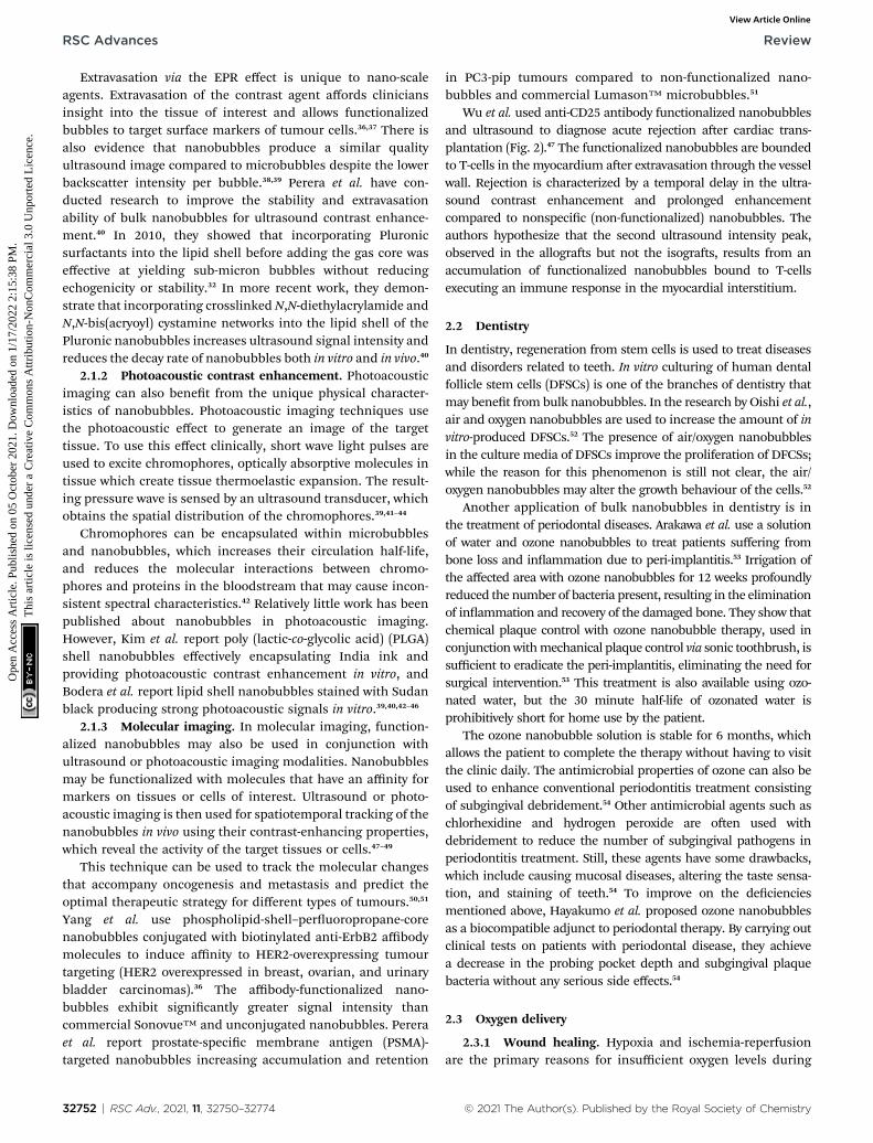
Wu et al. used anti-CD25 antibody functionalized nanobubblesand ultrasound to diagnose acute rejection aer cardiac trans-plantation (Fig. 2).47 The functionalized nanobubbles are boundedto T-cells in themyocardium aer extravasation through the vesselwall. Rejection is characterized by a temporal delay in the ultra-sound contrast enhancement and prolonged enhancementcompared to nonspecic (non-functionalized) nanobubbles. Theauthors hypothesize that the second ultrasound intensity peak,observed in the allogras but not the isogras, results from anaccumulation of functionalized nanobubbles bound to T-cellsexecuting an immune response in the myocardial interstitium.
2.2 Dentistry
In dentistry, regeneration from stem cells is used to treat diseasesand disorders related to teeth. In vitro culturing of human dentalfollicle stem cells (DFSCs) is one of the branches of dentistry thatmay benet from bulk nanobubbles. In the research by Oishi et al.,air and oxygen nanobubbles are used to increase the amount of invitro-produced DFSCs.52 The presence of air/oxygen nanobubblesin the culture media of DFSCs improve the proliferation of DFCSs;while the reason for this phenomenon is still not clear, the air/oxygen nanobubbles may alter the growth behaviour of the cells.52
Another application of bulk nanobubbles in dentistry is inthe treatment of periodontal diseases. Arakawa et al. use a solutionof water and ozone nanobubbles to treat patients suffering frombone loss and inammation due to peri-implantitis.53 Irrigation ofthe affected area with ozone nanobubbles for 12 weeks profoundlyreduced the number of bacteria present, resulting in the eliminationof inammation and recovery of the damaged bone. They show thatchemical plaque control with ozone nanobubble therapy, used inconjunctionwithmechanical plaque control via sonic toothbrush, issufficient to eradicate the peri-implantitis, eliminating the need forsurgical intervention.53 This treatment is also available using ozo-nated water, but the 30 minute half-life of ozonated water isprohibitively short for home use by the patient.
The ozone nanobubble solution is stable for 6 months, whichallows the patient to complete the therapy without having to visitthe clinic daily. The antimicrobial properties of ozone can also beused to enhance conventional periodontitis treatment consistingof subgingival debridement.54 Other antimicrobial agents such aschlorhexidine and hydrogen peroxide are oen used withdebridement to reduce the number of subgingival pathogens inperiodontitis treatment. Still, these agents have some drawbacks,which include causing mucosal diseases, altering the taste sensa-tion, and staining of teeth.54 To improve on the decienciesmentioned above, Hayakumo et al. proposed ozone nanobubblesas a biocompatible adjunct to periodontal therapy. By carrying outclinical tests on patients with periodontal disease, they achievea decrease in the probing pocket depth and subgingival plaquebacteria without any serious side effects.54
2.3 Oxygen delivery
2.3.1 Wound healing. Hypoxia and ischemia-reperfusionare the primary reasons for insufficient oxygen levels during
© 2021 The Author(s). Published by the Royal Society of Chemistry

Fig. 2 Ultrasound time–intensity curves (TIC) from myocardial contrast echocardiography of allografts and isografts imaged with functionalized andnon-functionalized nanobubbles. (A, C, and E) show TIC for isografts at 2, 4, and 6 days post transplantation, respectively. (B, D, and F) show TIC forallografts at 2, 4, and 6 days post transplantation, respectively. Note the delayed intensity peak in for allografts imagedwith functionalized nanobubbles.47
Review RSC Advances
Ope
n A
cces
s A
rtic
le. P
ublis
hed
on 0
5 O
ctob
er 2
021.
Dow
nloa
ded
on 1
/17/
2022
2:1
5:38
PM
. T
his
artic
le is
lice
nsed
und
er a
Cre
ativ
e C
omm
ons
Attr
ibut
ion-
Non
Com
mer
cial
3.0
Unp
orte
d L
icen
ce.
View Article Online
the wound healing process. Lack of enough oxygen ina wounded tissue extends the healing period, leading to irrep-arable damages, particularly in patients with diabetes.55–57 Two
© 2021 The Author(s). Published by the Royal Society of Chemistry
of the conventional treatments for maintaining the desiredoxygen level in a wound are hyperbaric oxygen and trans-obtu-rator tape therapy.58–61 However, these treatments are costly and
RSC Adv., 2021, 11, 32750–32774 | 32753

RSC Advances Review
Ope
n A
cces
s A
rtic
le. P
ublis
hed
on 0
5 O
ctob
er 2
021.
Dow
nloa
ded
on 1
/17/
2022
2:1
5:38
PM
. T
his
artic
le is
lice
nsed
und
er a
Cre
ativ
e C
omm
ons
Attr
ibut
ion-
Non
Com
mer
cial
3.0
Unp
orte
d L
icen
ce.
View Article Online
oen cause cellular toxicity. Moreover, they are not useful for allkinds of wounds. A replacement for the traditional therapies isutilizing oxygen nanobubbles, as their stability in solution helpsincrease the oxygen level in a wound over a prolonged period.Another advantage is their ability to trap a volume of oxygen,which can provide sufficient oxygen for the treatment byinjecting them into the damaged tissue. In addition to theoxygen delivery benets, the negative surface charge of oxygennanobubbles attracts debris and enhances the cleaning of thewound.62
2.3.2 Tumour hypoxia treatment. Tumour hypoxia maycause the survival of cancer cells in hypoxic areas.63,64 Further-more, in standard cancer therapies such as radiation andphotodynamic therapy in which obtaining the desired resultdepends on the sufficient level of oxygen in the tumour, hypoxiadeteriorates the effectiveness of the treatment.63–66
One of the possible methods to supply oxygen to tumourcells is using lipid-coated oxygen nanobubbles. The lipids onthe shell of the nanobubbles increase their stability, preventingthe release of oxygen before reaching the tumour. When usingnanobubbles, the release of the oxygen cargo is controllable andcan be performed by ultrasound stimulation.67,68 In a novelmethod proposed by Song et al., the nanobubbles are coatedwith a shell sensitive to pH changes.69 Acetylated dextran is usedas the pH-change sensitive polymer shell, which is disrupted inthe acidic environment of tumour cells (pH 6–6.5) and releasesoxygen within the tumour.69
Fig. 3 Schematic diagram depicting the pore formation and deliveryof fluids and macromolecules in the cell membrane. (a) Non-inertialcavitation causing pushing and pulling behaviour along the cellmembrane due to the expansion and compression of bubbles. (b)Inertial cavitation collapsing the bubble, rupturing the cell membraneand creating a transient pore. (c) Transmembrane fluid and macro-molecules, including plasmid DNA and oligonucleotides, transportedby nano/microbubbles travelling into cells through a transient pore.70
2.4 Tissue or organ-selective gene delivery by thecombination of ultrasound and nano/microbubbles or bubbleliposomes
Viruses have evolved to be efficient delivery systems for nucleicacids to specic cell types while avoiding immunosurveillance.This makes viruses an attractive delivery vehicle for genedelivery. In gene therapy, these types of viruses are also knownas viral vectors.71 There are several types of laboratory virusesthat have been modied to suit specic applications; however,their use has signicant limitations. Retroviral vectors allow forstable integration within the host cell; however, transductionrequires mitosis to occur, which can contribute to genomicinstability leading to cancer.71 For transient gene expression,adenoviral vectors are desirable due to their efficient trans-duction of genes; however, for genetic disorders where stablelong-term gene expression is needed, adenoviral vectors wouldnot be ideal. Herpes simplex virus (HSV) vectors are best knownfor their ability to infect nondividing cells and their delivery ofexogenous DNA; however, cell damage can occur due to theircytotoxic risks. Adeno-associated virus (AAV) vectors pose thelowest immunogenic risk among all of these viruses; however,AAV vectors have small cloning capacities, limiting their abilityto transduce larger genes greater than 5 kb.71
In recent years, ultrasound-mediated gene delivery systemswith nanobubbles have been developed as a non-viral vector genedelivery system that helps overcome some shortfalls of conven-tional viral approaches.70,72,73 In this system, transient pores areopened, by utilizing nano and microbubbles that interact with
32754 | RSC Adv., 2021, 11, 32750–32774
ultrasound, to disrupt the cell membrane. As a result, these poresallow the transfer and transduction of genetic material into thehost cell without the need for endocytosis (Fig. 3). This method isadvantageous as it provides a non-invasive and tissue-specic geneexpression approach to manipulating and exposing targetedtissues and organs with therapeutic genes through the use ofultrasound. Further, the use of lipid-coated nanobubbles alsoprovides low cytotoxic effects in vivo, reducing the inherent risk ofvector-specic immune responses and toxicity that is associatedwith using pathogenic viruses.70
Kida et al. examined the effectiveness of nanobubbles forgene delivery using a commercially available handheld ultrasoundscanner. Two studies were completed, one in vitro and one in vivo,with controls taken for each experiment.73 In the in vitro experi-ment, luciferase-expressing pDNA is introduced into HSC2 cells.Aer 24 hours, they found an increase in the luciferase expressionproportional to the concentration of the nanobubble in the solu-tion. A similar effect was also observed when the experiment wascompleted in vivo with ddY mice. In both groups, a signicantincrease in expression of the luciferase with the use of nano-bubbles and ultrasound was observed.73
2.4.1 Plasmid DNA delivery. In vitro studies have previouslybeen performed using the transfection method where cells sus-pended with microbubbles and plasmid DNA are exposed toultrasound for up to tens of seconds. Here, transfection efficiencyis affected by ultrasound exposure conditions, such as intensity,frequency, period, duty cycle, type, and microbubble concentra-tion. However, optimized conditions are not well understood tomaximize transfection efficiency. Aoi et al. developed herpessimplex virus mediated thymidine kinase (HSV-tk)-mediated
© 2021 The Author(s). Published by the Royal Society of Chemistry

Fig. 4 Preparation and use of nanobubble-GP3-rGO functionalized nanobubbles for NIR photothermal ablation of HCC.76
Review RSC Advances
Ope
n A
cces
s A
rtic
le. P
ublis
hed
on 0
5 O
ctob
er 2
021.
Dow
nloa
ded
on 1
/17/
2022
2:1
5:38
PM
. T
his
artic
le is
lice
nsed
und
er a
Cre
ativ
e C
omm
ons
Attr
ibut
ion-
Non
Com
mer
cial
3.0
Unp
orte
d L
icen
ce.
View Article Online
suicide gene treatment utilizing commercial Optison™ nano-bubbles and ultrasound.74 In this therapy, HSV-tk corded plasmidDNA and nanobubbles are injected into tumour tissue of mice,and ultrasound is transdermally exposed toward the targetedtissue. The reduction of tumour size is observed by administrationof ganciclovir in the mice transfected HSV-tk corded plasmid DNAwith nanobubbles and ultrasound.74
2.4.2 Oligonucleotide delivery. Oligonucleotides are shortsingle- or double-stranded polymers of nucleic acid that canstop the expression of a specic gene and be used to poten-tially develop new disease treatments for malignant, infec-tious, and autoimmune diseases.70 To achieve effective genesilencing, common oligonucleotides such as antisense, decoyand siRNA must be delivered to the cytoplasm of targetedcells to function properly. Combining ultrasound and nano-bubbles has been found as a useful method for deliveringextracellular molecules into the cytosol where oligonucleo-tides function best70 In an experiment conducted by Negishiet al., they reported that siRNA is directly introduced into thecytoplasm with only 10 seconds of nanobubble and ultra-sound exposure, providing an effective and efficient trans-fection of the oligonucleotide.75
Fig. 5 Comparison of tumour cell viability from different treatmentmethods tested. The combined therapy with NIR laser + ultrasound +functionalized nanobubbles yielded the best results, with a 72 hour cellviability of 2.26%.76
2.5 Tumour ablation
Thermal ablation is the process of inducing coagulativenecrosis in target tissues by producing transient temperature
© 2021 The Author(s). Published by the Royal Society of Chemistry
increase using high intensity focused ultrasound (HIFU), radi-ofrequency (RF) irradiation, microwave irradiation, laser irra-diation, cryoablation, and irreversible electroporation.77
RSC Adv., 2021, 11, 32750–32774 | 32755

RSC Advances Review
Ope
n A
cces
s A
rtic
le. P
ublis
hed
on 0
5 O
ctob
er 2
021.
Dow
nloa
ded
on 1
/17/
2022
2:1
5:38
PM
. T
his
artic
le is
lice
nsed
und
er a
Cre
ativ
e C
omm
ons
Attr
ibut
ion-
Non
Com
mer
cial
3.0
Unp
orte
d L
icen
ce.
View Article Online
These techniques are oen applied to non-invasively manageunresectable tumours of the liver, pancreas, bone, kidney, andlung.77–80 Several studies have shown that bulk nanobubbles candirectly increase the effectiveness of HIFU by increasingacoustic energy deposition in target tissues due to shear stress,cavitation, and streaming induced by nanobubble oscillationand collapse, and by controlled release of thermal sensitizersand anti-cancer drugs to the tumour.81–83 Yao et al. show thatlipid-shell nanobubbles and Sonovue™ Microbubbles exhibitsimilar volumes of coagulative necrosis, compared to nano-bubbles, in in vivo rabbit breast tumour models and excisedbovine livers for identical HIFU conditions, indicating that non-functionalized nanobubbles are an effective enhancer of HIFUtumour ablation.84
In another study, Liu et al. use target nanobubbles andultrasound to visualize and deliver reduced graphene oxide(rGO) nanosheets to in vitro hepatocellular carcinoma (HCC)HepG2 cells for enhanced near-infrared photothermal abla-tion.76 They conjugate glypican-3 (GP3), as a targeting moleculefor HepG2 cells, and rGO, for its photo-absorbing properties, to
Table 1 Summary of the biomedical applications of bulk nanobubbles
Current biomedical applications Summary
Ultrasound contrast enhancement Gas bubbles act as harmonic oscompressibility of the encapsulafrequencies and increase the inproduces sonograms with increechogenicity
Photoacoustic contrast enhancement Nanobubbles have shown to becontrast enhancement. Nanobuantigens, antibodies and other hincrease the specicity of photo
Molecular imaging Nanobubbles can be an ideal mconjunction with ultrasound ormolecular changes and predicttypes of tumours. Nanobubblestarget biomarkers of specic tisproperties of the bubbles can bebubbles to understand tissues o
Dentistry Bulk nanobubbles are utilized tocells and improve proliferation.dental bone reconstruction therbacterial properties
Wound healing As a replacement for hyperbaricoxygen nanobubbles can be injedeliver oxygen. Further, the negin the debridement process
Tumour hypoxia treatment Hypoxic environments deteriorathe survival of cancer cells. Lipiddeliver oxygen to tumours to all
Non-viral vector gene delivery Ultrasound-mediated gene delivinduce micro streams and micrfor genes to be delivered into ce
Tumour ablation High intensity focused ultrasoutumour ablation benet from thThey enhance the effectivenessacoustic energy deposition in tarcollapse as well as by the controlto tumours
32756 | RSC Adv., 2021, 11, 32750–32774
avidinylated phospholipid-shell nanobubbles to both deliverthe rGO to HCC HepG2 cells and provide ultrasound contrastenhancement to visualize the ablation process (Fig. 4).
The combined NIR laser, ultrasound, and functionalizednanobubbles therapy result in a 72 hour HCC HepG2 cell viabilityof 2.26%, signicantly lower than the other treatment methodstested, shown in Fig. 5. These studies have demonstrated theability of bulk nanobubbles to provide synergistic effects whenpaired with HIFU, laser and RF ablation. Compared to micro-bubbles, which have also been used for these types of treatments,tumour ablation therapies can benet from the increased bloodcirculation lifetime and tumour targeting ability offered by bulknanobubbles as a result of the EPR effect.76 Table 1 summarizesthe biomedical applications of bulk nanobubbles.
3. Characterization
Before the utilization of bulk nanobubbles in various applica-tions, it is oen necessary to rst investigate the nanobubbles'characteristics, including concentration, size, and
Reference
cillators, taking advantage of theted gas to resonate with ultrasoundtensity of the backscattered signal. Thisased contrast due to the high difference in
25, 29–37 and 85–87
effective mediums for photoacousticbble shells can be functionalized withigh biomarking affinitive molecules toacoustic imaging
38–40, 42 and 44
edium as molecular imaging markers inphotoacoustic imaging modalities to trackoptimal therapeutic strategies for differentcan be functionalized with molecules thatsues and cells of interest. The acousticused to temporally and spatially track then a molecular level
43, 45, 46, 48 and 49
stimulate the growth of dental follicle stemBulk nanobubbles have been employed asapy and for their anti-periodontopathic
47 and 50–54
oxygen and trans-obturator tape therapy,cted into damaged hypoxic tissue andative charge of the oxygen nanobubbles aid
55–61 and 88
te tumour treatment therapies and promote-coated nanobubbles have been applied toow for more effective treatment
63–69
ery systems make use of nanobubbles toojets to create transient pores which allowlls
70, 71, 73–75 and 89–91
nd and radiofrequency irradiation fore synergistic effects of bulk nanobubbles.of these treatments by increasing theget tissues through bubble oscillations andled release of thermal sensitizers and drugs
83 and 84
© 2021 The Author(s). Published by the Royal Society of Chemistry

Fig. 6 An embedded microchannel in a silicon microcantilever. Thecircled section highlights the tip of the microcantilever where thesensitivity is maximum.98
Fig. 7 Diagram illustrating the principle of NTA measurements usingthe Stokes–Einstein equation. Particles are illuminated by a laser lightand movements of the particles are recorded through the scatteredlight via a CCD by a microscope. The software tracks the Brownianmotion of each particle by determining the diffusion coefficient, andthen calculates the size as the mean square of the particle path usingthe Stokes–Einstein equation.99
Review RSC Advances
Ope
n A
cces
s A
rtic
le. P
ublis
hed
on 0
5 O
ctob
er 2
021.
Dow
nloa
ded
on 1
/17/
2022
2:1
5:38
PM
. T
his
artic
le is
lice
nsed
und
er a
Cre
ativ
e C
omm
ons
Attr
ibut
ion-
Non
Com
mer
cial
3.0
Unp
orte
d L
icen
ce.
View Article Online
polydispersity index, representing the nonuniformity ofa sample based on size. Due to the small scale, nanobubblemeasurements are difficult. In this section, we discuss currentcharacterization methods for bulk nanobubbles.
3.1 Dynamic light scattering (DLS)
DLS is used to describe a broad set of techniques for charac-terizing particle suspensions in liquids. These techniquestypically involve measuring the diffusion of particles ina suspension and calculating the particle size using a theoret-ical relationship. A monochromatic light source is directedthrough the sample, and the particles of interest scatter thelight in all directions. The dispersed light is received (typicallyby a photomultiplier) and produces a signal. The scattered lightundergoes constructive and destructive interference at differentlocations, resulting in spatially varying signal intensity which istracked over time.92,93 As the suspended particles undergo Brow-nian motion, the scattered light intensity uctuates over time, andthe spatial and time uctuations of the signal are detected by anautocorrelator to measure the time scale of particle motion. Theautocorrelation data is then used to calculate the size distributionof the suspended particles using models which account for thetemperature and solvent viscosity.94,95
DLS techniques allow for the sample particles to remain inthe liquid during characterization. Keeping particles insuspension during characterization ensures that bulk proper-ties, such as concentration and size distribution, can be accu-rately measured, and that individual particles are not modiedby the drying or evacuation processes necessary for some othersize characterization techniques including electron microscopy.Though DLS is widely used to characterize nanobubblesuspensions, it is not an ideal measurement technique for lipid-shelled nanobubbles or suspensions in which other nano-particles may be present because it cannot distinguish betweengas bubbles and other solid particles.96,97
3.2 Resonant mass measurement (RMM)
This method was rst introduced by T. P. Burg et al. in 2007.98 Thetechnology contains a silicone microcantilever continually oscil-lating at its resonance frequency. A microchannel is embeddedinside the microcantilever, and a uid containing nanoparticlespasses through the microchannel (Fig. 6).98 When a nanobubblecontaining uid passes through the microchannel, the resonancefrequency changes. An electric circuit that continually monitorsthe frequency of microcantilever converts the shi in frequency tothe buoyant mass of the nanobubbles.98
One of the advantages of this technique is that nanobubblescould be easily distinguished from non-gaseous nanoparticles.When the oating particle in the channels is a nanobubble, theresonance frequency increases. In contrast, for the nano-particles other than nanobubbles, it decreases. For sizemeasurements, the density of the particle needs to be known.One disadvantage of the RMMmethod is the high probability ofmicrochannel blockage. Therefore, samples should be renedvia a lter with pores smaller than the microchannel width andheight before any tests.
© 2021 The Author(s). Published by the Royal Society of Chemistry
3.3 Nanoparticle tracking analysis (NTA)
Nanoparticle tracking is a system for sizing particles fromaround 30–1000 nm with the lower limit of detection beingdependent on the refractive index of the nanoparticles. NTAutilizes video sequences to analyse Brownian motion throughthe illumination of the particles in a sample with a laser beam.The scattered light from particles is detected with a chargedcoupled device (CCD) or complementary metal oxide semi-conductor (CMOS) camera and converted to a digital signal forrecording. Specialized algorithms are used to detect individualparticles and track their path (Fig. 7).99
NTA has the capability of sample visualization and canprovide an approximate particle count and concentration. Meansize values that are obtained by NTA are smaller and closer to theexpected results of particle size tests compared to DLS.100 Further,NTA can prole the size distribution of particles to display thenumber of particles. As well, NTA allows for clear distinctionbetween different sizing populations and the ability to search andscan the sample for desired particles with the system's ability toseparately track every visible particle. One of the main drawbackswith NTA is the challenge of the operator to identify and setoptimal sample compositions and instrument settings such asnarrow particle concentration, and particle properties (shape,
RSC Adv., 2021, 11, 32750–32774 | 32757

RSC Advances Review
Ope
n A
cces
s A
rtic
le. P
ublis
hed
on 0
5 O
ctob
er 2
021.
Dow
nloa
ded
on 1
/17/
2022
2:1
5:38
PM
. T
his
artic
le is
lice
nsed
und
er a
Cre
ativ
e C
omm
ons
Attr
ibut
ion-
Non
Com
mer
cial
3.0
Unp
orte
d L
icen
ce.
View Article Online
refractive index and background noise) in order to yield the mostaccurate results. Moreover, NTA requires particle concentrationbetween 107 to 109 mL�1 while the required sample concentrationfor the DLS technique is less critical.101–104
3.4 Electron microscopy
Two less common techniques to characterize bulk nanobubblesare scanning electronmicroscopy (SEM) and transmission electronmicroscopy (TEM). These methods are commonly used to imagethe structure and the presence of bulk nanobubbles ina sample.105,106 Since they can only provide small elds of view, theyare not suitable for determining the concentration and averagesize of bulk nanobubbles in a sample. In electron microscopy,a beam of high voltage electrons is generated and accelerated ina chamber composed of different apertures and electromagneticlenses towards the sample. In SEM mode, the reected electronsfrom the sample are collected and analysed to achieve the samplesurface's image.While in TEMmode, the transmitted electrons arereceived and interpreted to collect information about the sample'sinner structure, including the crystal structure and morphology.TEM has better resolution (<50 pm) in comparison to SEM (z0.5nm); however, it is a more costly method than SEM. Furthermore,TEM's eld of view is considerably smaller than SEM and canimage a minimal area of the sample.105–108
Fig. 8 Polydisperse nanobubbles functionalized with Cy3-labeledcell-penetrating peptide (CPP) and FITC-labeled epidermal growthfactor receptor-targeted small interfering RNA (siEGFR), fabricatedusing the lipid film hydration agitation method for gene therapy oftriple negative breast cancer. (A) Nanobubbles fluorescing red, indi-cating effective loading of the CPPs in the bubble shell. (B) The samenanobubbles fluorescing green, indicating effective loading of thesiEGFR in the bubble shell.112
3.5 Cryo-EM visualization of nanobubbles
The sample containing the nanobubble suspension may berapidly frozen prior to electron microscopy to use a techniqueknown as cryogenic electron microscopy (cryo-EM). Usinga cryogen such as liquid nitrogen to freeze the sample quicklycauses the nanobubbles to be trapped in the resulting amor-phous ice, which maintains the sample's morphology withoutdeviations introduced by the crystallization of water.109 Thetrapped bubbles can then be imaged directly with TEM whilekeeping the sample frozen as in reports of Li et al.109 and Her-nandez et al.110 Alternatively, the frozen sample can be frac-tured, and the voids in the fracture planes representing theshells of the frozen bubbles can be coated for subsequent SEMor cast for subsequent SEM or TEM characterization.109–111
4. Current nanobubblemanufacturing methods
The performance of micro- and nanobubbles in the biomedicalapplications, and therefore treatment outcomes, are related tothe bubble manufacturing methods currently employed. In theparagraphs below, we outline the methods currently used tocreate nanobubble mixtures.
4.1 Mechanical methods
4.1.1 Agitation. For the purposes of this paper, “agitation”refers to mechanical shaking of a sealed vessel in which thereexists a gas, destined to be the bubble core, and a liquid, con-taining bubble shell materials, in contact with each other at aninterface. Agitation of this vessel introduces gas into the liquid
32758 | RSC Adv., 2021, 11, 32750–32774
to form bubbles. One of the early agitation methods to fabricatelipid-shell nanobubbles, described by Krupka et al., involvesdissolution of a solid lipid mixture in chloroform, followed byevaporation of the chloroform.32 Liposomes are then formed byhydration of the lipid lm with a PBS-glycerol solution in anincubator-shaker. The resulting solution is placed in vials whichare sealed with septum caps, and the air is removed andreplaced with octauoropropane. The vial is then shaken, oragitated, in a VialMix™ shaker for 45 s to form a polydispersesuspension of micro- and nanobubbles. The suspension is thencentrifuged with the vial inverted to isolate the nanobubblesfrom the microbubbles, aer which the nanobubbles can beremoved from the suspension by withdrawing the bottom 5mmof solution with a 21 G needle.32
Many extensions of the aforementioned method involve thesame mechanism of bubble formation, but incorporate othermolecules in the lipid shell to enhance stability, echogenicity,size, and surface affinity. One such method, described by thesame group, requires dissolution of the solid lipid mixture ina PBS-propylene glycol solution at elevated temperatures, fol-lowed by addition of glycerol.113 This solution is then trans-ferred to sealed vials and agitated as described earlier. Theinclusion of glycerol in the bubble shell increases the stiffness
© 2021 The Author(s). Published by the Royal Society of Chemistry

Fig. 9 Baffled high-intensity agitation (BHIA) cell used by Wu et al. togenerate bulk nanobubbles. After introducing the solution intoa baffled cell, the rotating impeller connected to a high-speed agitatorcreates hydrodynamic cavitation leading to the generation of bulknanobubbles. Valves 1 and 2 are used to take samples for the char-acterization of the generated bulk nanobubbles. The thumbscrews areplaced to tightly seal the cap cell to the cell body.118
Review RSC Advances
Ope
n A
cces
s A
rtic
le. P
ublis
hed
on 0
5 O
ctob
er 2
021.
Dow
nloa
ded
on 1
/17/
2022
2:1
5:38
PM
. T
his
artic
le is
lice
nsed
und
er a
Cre
ativ
e C
omm
ons
Attr
ibut
ion-
Non
Com
mer
cial
3.0
Unp
orte
d L
icen
ce.
View Article Online
of the shell as a result of hydrogen bonding, while the propyleneglycol increases the exibility of the shell.113 With both glyceroland propylene glycol included in the shell, the bubbles exhibi-ted superior in vivo stability compared to both FDA-approvedLumason™ ultrasound contrast agent, and Pluronicnanobubbles.
Other extensions of the agitationmethod can be found in theliterature.2,112,114 Fig. 8 shows functionalized bulk nanobubbleswith RNA.112 Tian et al. report a novel method for producingbulk nanobubbles using a gas–liquid mixing pump to introducefree nanobubbles in a degassed aqueous solution.115 Thismethod is similar to the agitation methods described earlier inthat it involves the production of a lipid lm via dissolution andsubsequent solvent evaporation. A gas–liquid mixing pump isused to mix degassed and deionized water (DI water) with sulfurhexauoride to create an aqueous suspension of nanobubbleswith a sulfur hexauoride core. This suspension is then addedto a vessel containing the lipid lm and allowed to incubate forhours to ensure self-assembly of the lipid molecules at all gas–liquid interfaces. This method does use mechanical agitation inthe gas–liquid pump as the primary mechanism of creatingbubbles, but self-assembly of the lipid molecules occurs aeragitation, as opposed to the simultaneous bubble formationand self-assembly in other methods.112
Agitation can yield very high bubble concentrations, 1011
mL�1, affording the user a signicant range of possibleconcentrations via post-fabrication dilution as required.97 Thisexibility allows researchers to tune the bubble suspension tosuit the application; for example, to avoid acoustic shadowingin ultrasound contrast enhancement, the nanobubble suspen-sion should be diluted to 108 to 109 mL�1.97 As with manyfabrication methods, it is not possible to control the mono-dispersity of the bubble population in real time. Consequently,researchers typically centrifuge the bubble suspension andremove a small volume from the bottom to isolate nanobubblesfrom microbubbles, yielding a sample of polydisperse nano-bubbles while the remainder of the suspension is discarded aswaste.116
4.1.2 Double-emulsion solvent evaporation. Kim et al.describe a process for making nanobubbles in which poly(lactic-co-glycolic acid) (PGLA) and methylene chloride solution,polyvinyl alcohol (PVA) and India Ink solution, and PVA solu-tion form a double-emulsion via ultrasonication.39 The doubleemulsion is added to an isopropanol solution and stirred. Themiddle phase of the double emulsion is polymerized to createspherical shells, which are used as nanobubble shells followinga process of washing, centrifugation, and freeze-drying. The IndiaInk is loaded in the bubble shell prior to polymerization for use asa chromophore for photoacoustic imaging. Several other groupshave created polymer shell nanobubbles using similar protocols,and have conjugated the nanobubbles with molecules such astumour-targeting proteins and anticancer drugs.83,117
The primary benet of this technique is that the bubbles canbe fabricated in large quantities due to the bulk nature of theultrasonication-based emulsication process. Conversely, itsuffers from a lack of real-time control over the size and mon-odispersity of the emulsion, both of which are important
© 2021 The Author(s). Published by the Royal Society of Chemistry
properties to maximize bubble ultrasound excitation resonancein contrast enhancement or drug delivery applications.
4.1.3 Hydrodynamic cavitation4.1.3.1 Hydrodynamic cavitation by a baffled high intensity
cell. In this method, bulk nanobubbles are produced using anapparatus called “baffled high-intensity agitation (BHIA) cell”.This setup consists of a sha that is connected to a high-speedagitator, two valves to take samples for characterization, andthumbscrews to highly seal the lid of the cell to the body. AsFig. 9 shows, a solution lls the cell, and an impeller is placedsuch that it does not make contact with any part of the cell. Theimpeller is then rotated at different RPM to create nanobubblesby hydrodynamic cavitation. The solution used in this tech-nique is a mixture of Milli-Q water, KCl as the electrolyte, NaOHand HCl as pHmodiers, and sodium dodecyl sulphate (SDS) asa surfactant to facilitate nanobubble generation. The size of thenanobubbles in this method depends on factors such as agita-tion speed, time, temperature of the solution, dissolved gascontent, and water chemistry. Wu et al. report yielding bulknanobubbles with a mean diameter of 500 nm and a lifetime ofabout 24 hours.118 One of BHIA cell's main advantagescompared with other cavitation techniques is the ability to havereal-time control of agitation speeds, which signicantly affectsthe size of the produced nanobubbles. Wu et al. found that theincrease in agitation speed with surfactant agents generatessmaller bubbles with higher concentrations.118
4.1.3.2 Hydrodynamic cavitation by using centrifugal multi-phase pump (CMP). To begin the nanobubble fabricationprocess using a CMP, atmospheric air is delivered into thesuction part of a CMP that is pre-lled with 40 L of DI water.This creates a mixture of gas and water inside the container.Different gas ows are used to facilitate the dissolution of air inwater. When the air is completely dissolved in water, the
RSC Adv., 2021, 11, 32750–32774 | 32759

Fig. 11 The experimental setup with the integration of a Y-typemicrofluidic cell used by Nirmalkar et al. for the generation of bulknanobubbles.12
RSC Advances Review
Ope
n A
cces
s A
rtic
le. P
ublis
hed
on 0
5 O
ctob
er 2
021.
Dow
nloa
ded
on 1
/17/
2022
2:1
5:38
PM
. T
his
artic
le is
lice
nsed
und
er a
Cre
ativ
e C
omm
ons
Attr
ibut
ion-
Non
Com
mer
cial
3.0
Unp
orte
d L
icen
ce.
View Article Online
mixture is pumped through a needle valve for nanobubblegeneration.120–122 Fig. 10 illustrates the CMP setup used byEtchepare et al.119 to generate nanobubbles within the range of150–200 nm. The highest concentration they reach is 4 � 109
mL�1.119 However, since they do not use any surfactants in thesolution, the lifetime of the generated nanobubbles is short.Calgaroto et al. also report producing bulk nanobubbles withthe smallest size of 150–180 nm. They utilize SDS and FlotigamEDA 3B as ionic and cationic surfactants, respectively, toimprove the lifetime of the nanobubbles.123
4.1.3.3 Hydrodynamic cavitation on a microuidic platform.In this method, nanobubble formation results from thehydrodynamic cavitation that occurs within a microuidicchamber. As water is passed through the device, nucleation ofnanobubbles occurs due to the high shear stresses and suddenchannel expansion at the junction of the device (Fig. 11). Thisphenomenon can be explained with Bernoulli's mechanical energyconservation principle, where the decrease in local pressure belowthe vapor pressure causes cavitation and the formation of tinybubbles in the liquid.12 The setup includes an inlet reservoir ofnon-degassed pure water connected to the Y-typemicrouidic chipwhere cavitation occurs. The resulting bubbles are then passedthrough a heat exchanger to decrease the temperature and nallypumped to the outlet for collection. The mean bubble diameterreported by Nirmalkar et al. remains constant at approximately130 nm, with a considerable population lasting up to 3 months.Their ndings also reveal a positive correlation between bubblenumber density and the pump's operating pressure at the inlet.12
Fig. 10 The generation of bulk nanobubbles in a semi-continuoussystem using a centrifugal multiphase pump (CMP). Atmospheric air isinjected into the CMP (item 4 in the figure) and passed through thepump impellers. The impeller's shear forces cause a multiphasic (air/liquid) flow, which is then subjected to different operating pressures tosaturate the air in the water. Then, the saturated water is forcedthrough the needle valve (item 9) for bubble generation throughhydrodynamic cavitation.119
32760 | RSC Adv., 2021, 11, 32750–32774
4.1.3.4 Compression–decompression. In this technique,developed by several different researchers, a high pressure gasis injected into a specic volume of a liquid using a needle.124–127
A plunger is employed to reach an optimal amount of mixingbetween the gas and the liquid. When the pressure of themixture is reduced to atmospheric pressure, the gas inside theliquid starts to form bubbles. Repeating the compression–decompression of the liquid–gas mixture leads to generation ofbulk nanobubbles. Recently, Jin et al. utilize this method toproduce bulk nanobubbles with a mean size of about 280 nmand size distribution of 100–800 nm.124
4.1.4 Surface electrostatic nanobubble formation. A novelmethod that is introduced by Ghaani et al. is using an electric eldto generate nanobubbles.128 The experimental setup for this tech-nique consists of a stainless-steel container that contains deion-ized water (Fig. 12). A connected tube to the container injectsa specic gas (methane or oxygen) to the container until achievinga gas saturated water. A xed electric eld about 12 kV m�1 isapplied to the water through the attached wires on the bottom ofthe container. The authors hypothesize that applying an electro-strictive force via an electric eld induces regions of negativepressure in a dielectric liquid, leading to the formation of nano-bubbles. The mean diameter of the nanobubbles increase fromabout 220 nm to 300 nm aer four months.128
4.1.5 Using graphene oxide sheets. If a surface exists whentwo miscible solvents which have different gas solubility aremixed with each other, gas supersaturation nucleation happenson the surface. Jannesari et al. utilize this phenomenon to makebulk nanobubbles.129 As seen in Fig. 13, the two misciblesolvents are warm water and NaCl solution, saturated with coldnitrogen. Graphene oxide (GO) sheets are used as the nucleationsurfaces for bulk nanobubbles. GO sheets are synthesized bya technique known as Hummers' method. Using a micro vortexplatform helped the nucleated nanobubbles on the surface ofthe GO sheets to detach and become bulk nanobubbles. Thediameter of the bulk nanobubbles is between 320–920 nm, withthe mean diameter around 545 nm.129
4.1.6 Shirasu-porous-glass (SPG) membranes. Kukizakiet al. introduce a setup, employing a Shirasu-porous-glassmembrane, to generate bulk nanobubbles.130 The primary
© 2021 The Author(s). Published by the Royal Society of Chemistry

Fig. 12 Pressure vessel rig used for creation of surface electrostatics nanobubbles. (A) Cross section of the pressure vessel that include the gassupplier, distribution terminal the pressure cell and the temperature regulation jacket. (B) DC current supply set up via sheath covered wires in a 3dimensional printed plastic.128
Review RSC Advances
Ope
n A
cces
s A
rtic
le. P
ublis
hed
on 0
5 O
ctob
er 2
021.
Dow
nloa
ded
on 1
/17/
2022
2:1
5:38
PM
. T
his
artic
le is
lice
nsed
und
er a
Cre
ativ
e C
omm
ons
Attr
ibut
ion-
Non
Com
mer
cial
3.0
Unp
orte
d L
icen
ce.
View Article Online
section of this setup is the membrane module, which housesa tubular glass membrane with submicron diameter poresthrough which water-SDS solution passes. Pressurized air isintroduced into the module outside of the glass membrane andforced into the owing solution by transmembrane pressuredifferential, resulting in nanobubble formation. Drag forcesacting on the bubble detach it from the pore and introduce itinto the bulk solution (Fig. 14). As a result, bulk nanobubblesform in the uid. The mean diameter of the produced nano-bubbles with this setup is 360–720 nm. The porous glassmembrane is made of a mixture of sodium carbonate, calciumcarbonate, magnesium oxide, and boric acid. To fabricate thetubular glass, a molding process is utilized and hydrochloricacid solution is used to make micro-holes on the surface of theglass. The nanobubbles generated with this method have bettersize monodispersity compared to the other methods.130
4.1.7 Ultrasonic irradiation. When water is irradiated byultrasound, ne bubbles are generated at nucleation sites, growto about resonance size under acoustic pressure uctuations,and collapse. The generation of bulk nanobubbles throughultrasonic irradiation reported by Yasuda et al. involves
Fig. 13 The schematic illustration of four different steps for bulknanobubbles creation through microvortices and graphene oxidesheets. In the first step (nucleation step), gas supersaturation nucle-ation caused by two miscible solvents with different gas solubilityforms nanobubbles on a graphene sheet (growth step). Warm waterand cold nitrogen saturated NaCl are the mentioned solvents. In thegrowth step, nanobubbles on the surface of the graphene sheet growuntil reaching their critical size and detach from the surface (detach-ment step) and form bulk nanobubbles inside the solution (bulk andsurface nanobubbles step).129
© 2021 The Author(s). Published by the Royal Society of Chemistry
a Langevin transducer attached to stainless steel vibrationplates at the bottom of a vessel, and a circulating water bath tomaintain constant temperature in the sample.131 The trans-ducer is controlled by a signal generator driven by a poweramplier to maintain a constant sinusoidal wave throughoutthe bubble generation process. During production, ultrapurewater is sonicated by the transducer which caused creation ofsubmicron bubbles through acoustic cavitation (Fig. 15). Theytest various ultrasound frequencies, from 22 kHz to 1 MHz, andreveal a trend of increasing nanobubble concentration withdecreasing ultrasound frequency, while the effect of frequencyon the mode nanobubble diameter is insignicant. They alsostudy the effect of ultrasonic power on nanobubble numberconcentration, and show that the concentration increases withultrasonic power. They report that the mode diameter of thegenerated bulk nanobubbles is within 90–100 nm for all
Fig. 14 Shirasu-porous-glass (SPG) membrane used to produce bulknanobubbles. The process starts by pumping a solution consists ofwater and sodium dodecyl sulphate (SDS) from the water phasestorage tank into the membrane module. Then, the compressed air ispurged into the membrane through the membrane holes to form bulknanobubbles inside the membrane. Then, the produced bulk nano-bubbles are collected in the storage tank. A flowmeter, a pressuregauge, and a laser diffraction particle size analyzer are used tomeasurethe flow of the water-SDS solution, air pressure, and size of thegenerated nanobubbles, respectively.130
RSC Adv., 2021, 11, 32750–32774 | 32761

Fig. 15 Ultrasonic irradiation apparatus that are used for generation of bulk nanobubbles. (a) Langevin transducer controlled by a signalgenerator attached to stainless-steel vibration plates. (b) Illustration of the generation of bulk nanobubbles.131
Fig. 16 Bulk nanobubbles generation via fragmentation of micro-bubbles. (a) A microbubble consists of bacteriochlorophyll–lipid andperfluorocarbon gas. (b) Production of bulk nanobubbles throughapplying low-frequency ultrasound to the bacteriochlorophyll–lipidshell microbubbles.132
RSC Advances Review
Ope
n A
cces
s A
rtic
le. P
ublis
hed
on 0
5 O
ctob
er 2
021.
Dow
nloa
ded
on 1
/17/
2022
2:1
5:38
PM
. T
his
artic
le is
lice
nsed
und
er a
Cre
ativ
e C
omm
ons
Attr
ibut
ion-
Non
Com
mer
cial
3.0
Unp
orte
d L
icen
ce.
View Article Online
conditions, and the concentration of the bubbles increases withincreasing the irradiation time, asymptotically reaching a valueof 1.5 � 109 mL�1.131
4.1.8 Microbubble fragmentation by ultrasound. Frag-mentation of microbubbles into nanobubbles is another tech-nique proposed by Huynh et al.132 They rst generatemicrobubbles using an agitation method and then convertthem to bulk nanobubbles by exposing them to low-frequency (1MHz), high duty-cycle (50%) ultrasound (Fig. 16). The shell ofthe microbubbles is porphyrin-lipid, and the core gas is per-uorocarbon. They show that the lipid-shell nanobubbles havean excellent multimodal imaging capability, effectivelyproducing ultrasound, photoacoustic, and uorescenceimaging enhancement. The lifetime of the generated nano-bubbles is about 22 days, measured by NanoSight LM10. Thenanobubbles produced with this method are polydisperse andhave a size distribution of 5–500 nm.132
4.1.9 Generation via nanoporous membrane. Ma et al. usea nanoporous alumina membrane to generate bulk nano-bubbles.133 The alumina membrane is composed of nanoholeswith a mean diameter of about 100 nm. The researchers employthe anodization technique as a simple, inexpensive, and effi-cient method to fabricate the membrane.133 To produce bulknanobubbles, they introduce gas through the nanoporousmembrane into a cell lled with DI water for 1 hour at a gaspressure of 1.5 atm.133 The gas passes through the nanopores, andaer pinching off from the nanopores in DI water, bulk nano-bubbles form. This approach produces CO2 bulk nanobubbleswithin the diameter range of 50–200 nm. Moreover, to investigatethe stability of the bulk nanobubbles, the authors use other gases,including nitrogen, oxygen, helium, and argon.133 They nd thatunder the same conditions, CO2 nanobubbles are smaller than theother gases due to their higher solubility in water. The producedbulk nanobubbles have a concentration of approximately 6 � 107
mL�1, which is acceptable for several in vivo and in vitro biomed-ical applications. However, the technique they introduce, like othermethods mentioned earlier, cannot precisely control nanobubblediameter. Moreover, the lifetime and polydispersity index of thegenerated bulk nanobubbles have not been investigated.133
32762 | RSC Adv., 2021, 11, 32750–32774
4.2 Chemical methods
4.2.1 Electrolysis. The generation of nanobubbles via anelectrochemical cell is another method that has been used overthe past few years. As shown in Fig. 17, the setup is composed oftwo electrodes that are xed in a cell and connected to an externalpower supply. By applying a voltage to the electrodes, the electricalcurrent from anode to cathode electrolyzes the water in the cell.The result of the electrolysis reaction is the formation of oxygennanobubbles in the anode side of the cell.135,136Kikuchi et al. reportthe production of bulk oxygen nanobubbles with an initial size of
© 2021 The Author(s). Published by the Royal Society of Chemistry

Fig. 17 Production of bulk nanobubbles through the electrolysistechnique. An electrolyte solution passes from a filter with 100 nmholes before being merged with gas (O2 or N2) in the tank. Then, themixed solution with gas in the tank transports to the chamber wherethe electrodes are placed. The electric current passing from theelectrode anode to the cathode electrode electrolyzes the waterinside the chamber.134
Review RSC Advances
Ope
n A
cces
s A
rtic
le. P
ublis
hed
on 0
5 O
ctob
er 2
021.
Dow
nloa
ded
on 1
/17/
2022
2:1
5:38
PM
. T
his
artic
le is
lice
nsed
und
er a
Cre
ativ
e C
omm
ons
Attr
ibut
ion-
Non
Com
mer
cial
3.0
Unp
orte
d L
icen
ce.
View Article Online
30 nm. Three days aer the generation of the bulk nanobubbles,the nal size of the nanobubbles increases to 250 nm, and thenanobubbles gradually disappear as a result of dissolution ofoxygen from the bubbles.134
4.2.2 Plasma. Sato et al. use plasma to generate nano-bubbles.138 In their experimental setup, one side of a platinumwire electrode is placed inside a water container, and the otherside is connected to a power supply.137 A platinum ring electrodeconnected to the power supply, and a ground electrode is placedunder the bottom of the water vessel. A voltage within the rangeof �3.5 to �5.5 kV with a frequency of 10 kHz is applied to theelectrode that generate plasma emission at the tip of the wireelectrode. They explain that underwater plasma emissioncreates gas channels along “streamer discharges”, whichcollapse to form bulk nanobubbles with the mean diameter of120 nm and the size distribution of 50–400 nm (Fig. 18).137
4.3 Discussion
Altogether, principal characteristics, including concentration,polydispersity index, real-time control on bubble size, and thelifetime of the generated bulk nanobubbles distinguish the
Fig. 18 Schematic of the experimental setup to form bulk nano-bubbles via plasma generation in a specific volume of water. Theplasma forms between the electrode tip placed in the water and thegrounded electrode after turning on the high-voltage power supply.137
© 2021 The Author(s). Published by the Royal Society of Chemistry
production methods from each other. In this section, we delveinto the advantages and disadvantages of the existing bulknanobubble manufacturing techniques and examine theirbiomedical applications.
In general, agitation-based techniques produce bulk nano-bubbles with high concentrations, which can then be diluted tolower concentrations for specic applications. Namely, de Leonet al. are able to reach a concentration of up to 1011 mL�1.113 Thegas used in these methods are typically peruorocarbons, whichhave very low solubility in a aqueous phase.139 As a result, thelifetime of bulk nanobubbles produced via agitation is pro-longed. However, high polydispersity index and lack of real-timecontrol on the size of the nanobubbles are the foremost draw-backs of these agitation-based methods.
Bulk nanobubbles generated via agitation methods havebeen employed in molecular imaging as ultrasound and pho-toacoustic contrast agents.2,39,42,47 Biomedical applicationswhose results do not depend on a low nanobubble poly-dispersity index can benet from the generation methods basedon agitation.
Another conventional method to manufacture bulk nano-bubbles is using the hydrodynamic cavitation technique. Themain advantage of this method is its ability to producemoderately highly concentration bulk nanobubbles (108 to 109
mL�1).120,121 A downside of employing the hydrodynamicmethod is the large footprint of the generation setups requiredfor this technique. So far, nanobubbles produced through thistechnique have only been employed in non-medical applica-tions, including mineral and food processing. Nevertheless, theability of this method to fabricate concentrated bulk nano-bubbles may assist in biomedical applications that demandhighly-concentrated nanobubbles in large quantities.
One of the practices to avoid Ostwald ripening, whichdecreases the lifetime and causes an undesirable high poly-dispersity index, is coating a nanobubble surface with a stabi-lizing shell. Functionalizing a nanobubble surface with a lipidlayer could improve the nanobubble stability and mono-dispersity by reducing the surface tension, resulting a decreasein the Laplace pressure according to the Young–Laplace equa-tion.140 In diagnostic and therapeutic applications such as invivo ultrasound imaging, ultrasound-mediated gene delivery,and tumour ablation, coating the nanobubbles in a stabilizingshell prolongs the circulation time, which in turn extends thetime window for contrast-enhanced ultrasound imaging.141,142
Consequently, the manufacturing techniques that producesolely non-lipid shell nanobubbles might be less reliable forbiomedical applications that require stable monodisperse bulknanobubbles for optimal efficacy. These methods include gra-phene oxide sheets, ultrasonic irradiation, and plasma.
Among the nanobubble generation techniques described inthis review, electrolysis produces the most concentrated bulknanobubbles (1018 to 1021 mL�1).134,135 This advantage isimportant in dentistry since enhancing nanobubble concen-tration induces a signicant boost in stem cell proliferation,leading to efficiency improvement. However, in this method, itis not technically possible to precisely control the size of thenanobubbles. Moreover, the produced nanobubbles are not
RSC Adv., 2021, 11, 32750–32774 | 32763

RSC Advances Review
Ope
n A
cces
s A
rtic
le. P
ublis
hed
on 0
5 O
ctob
er 2
021.
Dow
nloa
ded
on 1
/17/
2022
2:1
5:38
PM
. T
his
artic
le is
lice
nsed
und
er a
Cre
ativ
e C
omm
ons
Attr
ibut
ion-
Non
Com
mer
cial
3.0
Unp
orte
d L
icen
ce.
View Article Online
stable; Kikuchi et al. report a signicant change in the size ofthe produced nanobubbles via electrolysis from 30 nm to250 nm within three days.134
On the contrary, the surface electrostatic method may generatereasonably stable nanobubbles. Ghaani et al. use this technique toform bulk nanobubbles with a mean diameter of around 220 nm,increasing to 300 nm aer four months.128 However, since theauthors have not reported nanobubble concentration and poly-dispersity index, it is unknown whether such nanobubbles can beused inmedical applications.One factor that canmake a differencein whether bulk nanobubbles can be utilized in applications is thetype of gas encapsulated inside the nanobubbles. In tumourhypoxia treatment and wound healing, oxygen bulk nanobubblesare required to secure a satisfactory level of oxygen in the damagedhypoxic tissues.62,69 To this end, generation via nanoporousmembrane might be an ideal approach to ll the nucleus ofnanobubbles with oxygen.133 However, in this method, the size ofthe nanobubbles is dictated by the diameter of the membranenanopores. As such, this method is not appropriate for applica-tions that need real-time control over the bubble size.
Lastly, microbubble fragmentation can be employed asa simple and straightforward technique to manufacture lipid–shell bulk nanobubbles.132 However, since the ultrasonic radi-ation intensity is not uniform over the sample containing themicrobubbles, a homogeneous size distribution cannot be ob-tained, deteriorating the polydispersity index. Huynh et al. usethe nanobubbles produced using this technique as contrastagents in photoacoustic imaging.132 To summarize, based onthe requirements of the applications of nanobubbles, an idealnanobubble production method would have a high throughput,and make monodisperse and high-concentration nanobubblesthat are stable and can be functionalized. Though all the tech-niques we have reviewed fulls one or more of these criteria, nota single method realizes the entire criteria set.
Microuidics has the potential to be utilized as a trans-formative technique for nanobubble generation. This is becausethe requirements of size control, high concentration, and mono-dispersity have been addressed by microuidics researchers inmaking bulk microdroplets and microbubbles.87,143–146 The majorchallenge for microuidics would be to further scale down thebubble size, so that nanoscale bubbles can be generated. InSection 5, we discuss how microuidics can contribute toproducing monodisperse bulk nanobubbles. Table 2 summarizesthe specications of the available production techniques.
5. Nanobubble generationopportunities for microfluidics
Bulk nanobubbles with the characteristics of controllable size,monodispersity, and high concentration, further the develop-ment of several important biomedical applications. In thissection, we rst outline the existing techniques use micro-uidics to produce bulk nanobubbles. Then, we propose twoadditional ideas to engineer microuidic devices that generatebulk nanobubbles with the characteristics that are highlydesirable in many biomedical applications.
32764 | RSC Adv., 2021, 11, 32750–32774
5.1 Existing technique 1: microuidic atomization
In the atomization method described by Peyman et al.,148
a microuidic device consisting of a central gas inlet channeland two opposing liquid inlet channels form a ow focusinggeometry, allowing for atomization-like ow focusing produc-tion of both micro- and nanobubbles. In the experiment illus-trated in Fig. 19, a peruorocarbon gas is injected in the gasinlet and a lipid solution is injected into the liquid inlet chan-nels, to create a ow focusing production stream. Shear stressesand pressure changes at the channel expansion create anatomization-like phenomenon, producing microbubbles anda ne spray of particles that are nanometers in size. The parti-cles consist of a mixed population of nanobubbles and per-uorocarbon particles.
Subsequently, a passive separation method is used to sepa-rate the nanoparticles and microbubbles. The separationmethod relies on the intrinsic buoyancy of the bubbles. Nano-particle tracking analysis is used to characterize the nano-bubbles and the authors nd a high number concentration ofparticles produced, around 1010 mL�1, for particles within therange of 100–300 nm. The authors do not report the poly-dispersity index of the produced nanobubbles, and the ability ofthis technique to control the size of the nanobubbles is notinvestigated.
Some of the main advantages of using this microchip-microspray approach include its ease of operation, high repro-ducibility, and low manufacturing costs. Experiments for tar-geted drug delivery demonstrate this technique as a rapid,single-step, nanobubble functionalization method.148
5.2 Existing technique 2: microuidic shrinkage
Our group has recently reported a method for generatingmonodisperse lipid-shell nanobubbles using a microuidicdevice.149 In this method, monodisperse microbubbles aregenerated in a microuidic ow-focusing platform. Shrinkageenables the transformation of microbubbles into nanobubbles.To achieve this, the gas core consists of a mixture of two gases,one of which is highly soluble in the liquid phase, and anothergas that is weakly soluble. Aer the generation of microbubbles,the highly soluble gas component dissolves in the liquid phase,leaving the weakly soluble component as the gas core of a muchsmaller bubble (Fig. 20).149
The nal diameter of the shrunk bubbles can be adjusted bymodifying design parameters, including core gas compositionand the width of the ow focusing junction. This method offersreal-time control over the monodispersity, size, and productionrate of the resulting nanobubbles, simply by adjusting the owconditions, such as gas pressure and liquid ow rate, within thedevice. It is also the rst known method for creating mono-disperse nanobubbles, with a favourable polydispersity index of0.11, at a sufficient throughput for biomedical applications.149
A drawback of this method is the existence of an upper limitof the bubble concentration, due to the nature of the shrinkageprocess. To achieve maximum concentration, spherical bubblesmust assume a “close-packed” arrangement. The number ofbubbles per unit volume, pre-shrinkage, determines the
© 2021 The Author(s). Published by the Royal Society of Chemistry

Table 2 Summary of each nanobubble generation method
Technique
Nanobubblesize range(nm)
Nanobubbleconcentration(mL�1)
Polydispersityindex Shell material Core material
Refno
Agitation 200–400 105 0.005–0.0296 Pluronic Octauoropropanegas
85
No data – 270 1011 No data Phospholipid Octauoropropanegas
113
180–200 No data 0.09–0.21 Phospholipid Octauoropropanegas
114
No data – 580 108 No data Phospholipid Octauoropropanegas
115
No data – 430 109 No data Phospholipid Octauoropropanegas
2
Double emulsion polymerization No data – 290 No data No data Polymer Air 37Hydrodynamic cavitation bya baffled high intensity cell
280–730 No data < 0.35 DI water, sodium dodecyl sulfate, methylisobutyl carbinol or methyl amyl alcoholand DF250
CO2 118
150–650 No data No data DI water, methyl isobutyl methanol, N-pentanol
Air 18
Hydrodynamic cavitation by usingcentrifugal multiphase pump(CMP)
50–400 109 No data DI water, a-terpineol solution Air 120100–550 108 No data DI water, pine oil Air 121150–400 109 No data DI water, a-terpineol Air 122No data – 220 108 No data DI water, aluminum sulfate, non-ionic
high-molecular-weight polyacrylamideocculan
Air 119
Hydrodynamic cavitation ona microuidic platform
No data – 130 108 No data DI water Air 12
Compression–decompression 100–800 109 0.18 DI water Xe, air, SF6 147150–720 No data No data DI water, sodium dodecyl sulphate,
methyl ether monoamine alkylAir 123
Surface electrostatic nanobubble 220–300 No data No data DI water Oxygen, methane 135Using graphene sheets 320–920 109 No data DI water, NaCl Nitrogen 129Shirasu-porous-glass (SPG)membranes
360–720 No data 0.45–0.48 DI water, sodium dodecyl sulfate Air 130
Ultrasonic irradiation 50–220 106 No data DI water Air 131Microbubble fragmentation 0–500 7 � 106 No data Phospholipid Octauoropropane
gas132
Generation via nanoporesmembrane
50–200 6 � 107 No data DI water, sodium laureth sulfate CO2, O2, N2, ar, He 133
Electrolysis 30–250 No data No data DI water, NaOH, MnSO4 No gas required 136No data – 200 1021 No data Water, Na2SO4 No gas required 13560–80 1018 No data DI water, Na2SO4 No gas required 134
Plasma 50–400 No data No data DI water Air 116
Review RSC Advances
Ope
n A
cces
s A
rtic
le. P
ublis
hed
on 0
5 O
ctob
er 2
021.
Dow
nloa
ded
on 1
/17/
2022
2:1
5:38
PM
. T
his
artic
le is
lice
nsed
und
er a
Cre
ativ
e C
omm
ons
Attr
ibut
ion-
Non
Com
mer
cial
3.0
Unp
orte
d L
icen
ce.
View Article Online
maximum possible concentration, as shrunk bubbles cannotpossibly assume the same arrangement. Increasing theconcentration limit would require reducing the initial micro-bubble diameter to accommodate more bubbles per unitvolume. This would necessitate more complex device fabrica-tion protocols as initial microbubble diameter is dependent onthe width of the ow-focusing orice. We report concentrationsup to 108 mL�1 and show that this is acceptable for ultrasoundcontrast enhancement, but this does not currently allow for theexibility provided by, for example, the agitationmethod, whichcan yield concentrations up to 1011 mL�1.149
5.3 Nanobubble generation possibilities with microuidics
The two aforementioned studies on utilizing microuidics toproduce bulk nanobubbles demonstrate that, despite somepossible drawbacks, microuidics may be able to address the
© 2021 The Author(s). Published by the Royal Society of Chemistry
limitations of conventional production methods. For instance,the design recently published by our group provides the func-tionality of real-time nanobubble size control, with a low poly-dispersity index, which addresses a major challenge for almostall bulk nanobubble manufacturing methods.149 Furthermore,using a microuidic ow-focusing design facilitates the possi-bility of forming nanobubbles with combinations of variousgases, by simply supplying different gases, and their mixtures,as the dispersed phase. This feature of microuidics providesexibility for many nanobubble-based biomedical applications.
In the sections below, we present two additional potentialmicrouidics research projects that may contribute toimproving the size range of and/or throughput of microuidicnanobubble generation.
5.3.1 Reducing microuidic ow focusing junction widthusing DRIE. A ubiquitous microuidic geometry utilized to
RSC Adv., 2021, 11, 32750–32774 | 32765

Fig. 19 (a) Microscopic image of a microfluidic flow focusing geometry with a 3D expansion, illustrating the atomization-like production ofmicrobubbles, and fine-spray production of nanoparticles. (b) Histogram depicting an optically counted concentration distribution of particles,reported by Peyman et al. The optical limit of 0.75 mm is reached within the green shaded region.148
RSC Advances Review
Ope
n A
cces
s A
rtic
le. P
ublis
hed
on 0
5 O
ctob
er 2
021.
Dow
nloa
ded
on 1
/17/
2022
2:1
5:38
PM
. T
his
artic
le is
lice
nsed
und
er a
Cre
ativ
e C
omm
ons
Attr
ibut
ion-
Non
Com
mer
cial
3.0
Unp
orte
d L
icen
ce.
View Article Online
generate bulk microbubbles is the ow focusing design. Thisdesign is typically built using the typical method of patterningPDMS, and then bonding the PDMS to a glass slide.150–161 Asshown in Fig. 21, in the ow focusing technique, two liquidsheath ows from the side channels cut off the gas ow fromthe central channel at the orice location. As a result, the gasphase breaks up into microbubbles surrounded by the liquidcontinuous phase. With this geometry, the diameter of micro-bubbles depends on the liquid ow rate, gas ow rate, andorice width. Eqn (3) shows the relationship between thediameter of a microbubble and the mentioned parameters,162
Fig. 20 A microfluidic nanobubble generator that is recently reported bshowing liquid (lipid solution), gas and reservoir inlets. The serpentine stinto nanobubbles by a microscope. (b) The flow-focusing section of theand length of the orifice are 20 mm and 100 mm, respectively. Following tthe entry of the microbubbles into the serpentine microchannel. The widdevice is 50 mm. (c) The gradual outflowof nitrogen from the cores ofmicshrinkage. In contrast, C3F8 remains inside the bubble's core due to its lowSample 1 is the control group consisting of lipid solution, and samples 2200 nm, respectively.149
32766 | RSC Adv., 2021, 11, 32750–32774
db
Df
�Qg
Ql
�0:4
; (3)
where db is the diameter of a bubble, D is the width of the oriceand Qg and Ql are the gas and liquid ow rates, respectively. Asstated by eqn (3), decreasing the width of the orice causesa reduction in the microbubble diameter. However, due to thelimitations of the so lithography process, which is a commonmethod to fabricate microuidic devices, achieving orices withwidths less than 5 mm is an arduous and demanding task in thefabrication of PDMS-based microstructures. Generating nano-bubbles by decreasing the orice width to less than 5 mm has
y our group. (a) Top-view schematic diagram of the microfluidic chip,ructure of the design facilitates the tracking of microbubble shrinkagemicrofluidic chip to generate monodisperse microbubbles. The widthhe generation of the microbubbles, the shrinkage process begins withth of this microchannel is 350 mm, and the height of all channels in therobubbles and dissolution into the aqueous phase leads tomicrobubblesolubility. (d) Three different samples are taken from the reservoir inlet.and 3 contain bulk nanobubbles with mean diameters of 100 nm and
© 2021 The Author(s). Published by the Royal Society of Chemistry

Fig. 21 Top-view schematic diagram of a planar flow focusing designto produce bubbles.
Fig. 22 Microbubble production by flow focusing. (a) A schematicdrawing, and (b) microscopic image of flow focusing geometries. In (a),QD, QC, and Wup represent the gas flow rate, liquid flow rate, anddistance between the device wall and the gas channel, respectively. In(b), the orifice width, the gas flow channel width, and the junction-to-orifice distance is shown by WOR, 2a, and DZ, respectively.154
Review RSC Advances
Ope
n A
cces
s A
rtic
le. P
ublis
hed
on 0
5 O
ctob
er 2
021.
Dow
nloa
ded
on 1
/17/
2022
2:1
5:38
PM
. T
his
artic
le is
lice
nsed
und
er a
Cre
ativ
e C
omm
ons
Attr
ibut
ion-
Non
Com
mer
cial
3.0
Unp
orte
d L
icen
ce.
View Article Online
not been discussed in other papers so far. We believe one of thereliable solutions to this matter is replacing the PDMS substratethat comprises microchannels with silicon and utilizing stan-dard micro/nano machining processes in the Micro ElectroMechanical Systems (MEMS) eld to fabricate orices withultra-high aspect ratios. Deep Reactive Ion Etching (DRIE) isone of the conventional MEMS procedures to fabricate nemicro/nano structures such as micro/nanochannels. Forexample, Parasuraman et al. fabricate silicone trenches with
Fig. 23 Generation of bulk microbubbles through (a) flow-focusing technsilicone and reducing the orifice width to achieve bulk nanobubbles.
© 2021 The Author(s). Published by the Royal Society of Chemistry
99.49 mm height and 800 nm width, which shows the capabilityof the DRIE technique to fabricate high aspect ratio micro/nanostructures.163
Alternatively, a reduction in bubble diameter can also beachieved by increasing the liquid ow rate to transition fromthe geometry-controlled regime, in which bubbles have a sizealmost equal to the orice width, to the dripping regime. Thisregime can be achieved by changing the capillary number,which is dened as
Ca ¼ m0Ga
gEQ
¼ m0aDV
gEQDZ¼ m0aQC
gEQhDZ
�1
WOR
� 1
2WUP
�; (4)
where m0 is the dynamic viscosity of the liquid, G is the elon-gation rate, a is the half-width of the channel that carries thegas, and yEQ is the equilibrium surface tension. The elongationrate can be dened as G ¼ (Vc � Vu)/DZ, where Vc and Vu are thelargest and the smallest uid velocity at the orice, respectively,and DZ is the liquid channel width. In eqn (4), DV ¼ Vc � Vu canbe written as QC/h � (1/WOR � 1/2WUP), where QC is the liquidow rate, h is the height of the channels, and WOR and WUP arethe width of the orice and the channels that carry the liquid,respectively (Fig. 22).154
It is worth mentioning that in miniaturizing the orice,some critical issues should be considered. During operation,blockage of the orice is one of the problems that may arise dueto reducing the orice width.
To prevent the probable clogging, the solution (continuousphase) should be ltered through syringe lters with poressmaller than the orice width. Moreover, in designing the ow-focusingmicrouidic device, ltering micro channels should beconsidered to prevent orice clogging. Fig. 23 briey illustratesthe proposed idea of producing nanobubbles via reducing theorice width in a bulk microbubble generator microuidicdevice with a ow-focusing design.
5.3.2 Parallelized nanobubble production by embeddinga nanoporous membrane. Another approach to produce bulkmonodisperse nanobubbles, with increased throughput, is toembed a silicone nanoporous membrane with uniformly sized
ique in a microfluidic device and (b) replacing the PDMS substrate with
RSC Adv., 2021, 11, 32750–32774 | 32767

Fig. 24 Production of bulk monodisperse nanobubbles via anembedded silicone nanoporous membrane in a PDMS microfluidicchip.
RSC Advances Review
Ope
n A
cces
s A
rtic
le. P
ublis
hed
on 0
5 O
ctob
er 2
021.
Dow
nloa
ded
on 1
/17/
2022
2:1
5:38
PM
. T
his
artic
le is
lice
nsed
und
er a
Cre
ativ
e C
omm
ons
Attr
ibut
ion-
Non
Com
mer
cial
3.0
Unp
orte
d L
icen
ce.
View Article Online
pores, into a microuidic planar ow focused design. Fig. 24shows a schematic diagram of the proposed idea.
In this design, the continuous liquid phase and the dispersedgas phase are forced toward the nanopores by creating a pressuregradient. The liquid ow from the lateral microchannels squeezesthe gas through the nanoporous membrane location, passing thenanoholes. As a result, nanobubbles should form and pinch off ateachmembrane hole, into the outlet channel. Since the nanoporesare uniformly sized, the generated bulk nanobubbles should havea low polydispersity index.
This design should facilitate higher nanobubble generationthroughput. Since bubble shrinkage is not needed in this design,the concentration limit in our recent work could be drasticallyimproved.149 In addition to reducing the polydispersity index, itmay be possible to control the size of the nanobubbles here bysimply changing the gas and liquid pressure. This approachshould also be manufacturable using conventional so lithog-raphy processes.164,165 To embed the nanoporous siliconmembrane inside the chip, we propose the standard oxygenplasma process. Moreover, ready-made nanoporous membranescan be utilized instead of fabricating a nanoporous membrane viaanodization techniques, to minimize manufacturing complexity.
6. Conclusion
Nanobubbles can be used in many applications, from industrialto medical. Indeed, bulk nanobubbles are already utilized in sometherapeutic and diagnostic applications because of their uniqueacoustic and transport properties. Consequently, various methodshave been introduced to generate bulk nanobubbles. However,despite the progress made in the eld of nanobubble generation,there are still some important drawbacks that limit nanobubblewidespread utilization. In many of the biomedical applications of
32768 | RSC Adv., 2021, 11, 32750–32774
bulk nanobubbles, such as imaging, better nanobubble mono-dispersity would potentially signicantly improve outcomes.However, the currently utilized bulk nanobubble generationmethods generally make polydisperse nanobubbles, and lack real-time size control capabilities.
Microuidics has emerged as a tool that has mass productioncapability, and precise uid ow controllability. With additionalinnovations, microuidics may be developed to overcome existingnanobubble production challenges, tomake better nanobubbles forbiomedical applications. Evidence of this claim can be seen in thenumber of published papers in recent years in the eld of nano-droplet and bulk microbubble production. We hope this reviewdemonstrates that nanobubble generation is a highly impactful areaof research, and that microuidics researchers have an importantrole to play in developing the next generation of highly tunable,monodisperse, and high concentration nanobubbles. In biomedicalapplications, that could improve diagnostic and therapeuticmodalities, and ultimately, patient outcomes. We also propose twomicrouidic methods to address the drawbacks of the current bulknanobubble generation techniques.
Conflicts of interest
The authors declare no conict of interest.
Acknowledgements
SSHT is thankful for research funding from the Canada Foun-dation for Innovation (CFI 36687 and 36442), and the NaturalSciences and Engineering Research Council (NSERC) of CanadaDiscovery grants program (RGPIN-2019-04618). MCK is thank-ful for research funding support from the Canada Foundationfor Innovation (CFI 30994), NSERC Discovery Grant (RGPIN-2017-06496), and the NSERC/CIHR Collaborative HealthResearch Projects (NSERC/CIHR - CPG 146484). The authorswould like to thank Katherine Chan from Ryerson University forediting early dras of the manuscript, and Amir MohammadSeif from Tehran University for assistance in making thegraphical contents of Section 5.
References
1 B. D. Johnson and R. C. Cooke, Generation of stabilizedmicrobubbles in seawater, Science, 1981, 213(4504), 209–211.
2 T. Yin, P. Wang, R. Zheng, B. Zheng, D. Cheng, X. Zhang,et al., Nanobubbles for enhanced ultrasound imaging oftumors, Int. J. Nanomed., 2012, 7, 895–904.
3 P. Attard, M. P. Moody and J. W. G. Tyrrell, Nanobubbles:The big picture, Phys. Stat. Mech. Appl., 2002, 314(1–4),696–705.
4 J. Zhu, H. An, M. Alheshibri, L. Liu, P. M. J. Terpstra, G. Liu,et al., Cleaning with bulk nanobubbles, Langmuir, 2016,32(43), 11203–11211.
5 J. N. Meegoda, S. Aluthgun Hewage and J. H. Batagoda,Stability of nanobubbles, Environ. Eng. Sci., 2018, 35(11),1216–1227.
© 2021 The Author(s). Published by the Royal Society of Chemistry

Review RSC Advances
Ope
n A
cces
s A
rtic
le. P
ublis
hed
on 0
5 O
ctob
er 2
021.
Dow
nloa
ded
on 1
/17/
2022
2:1
5:38
PM
. T
his
artic
le is
lice
nsed
und
er a
Cre
ativ
e C
omm
ons
Attr
ibut
ion-
Non
Com
mer
cial
3.0
Unp
orte
d L
icen
ce.
View Article Online
6 J. L. Parker, P. M. Claesson and P. Attard, Bubbles, cavities,and the long-ranged attraction between hydrophobicsurfaces, J. Phys. Chem., 1994, 98(34), 8468–8480.
7 G. S. Manning, On the thermodynamic stability of bubbles,immiscible droplets, and cavities, Phys. Chem. Chem. Phys.,2020, 22(31), 17523–17531.
8 P. S. Epstein and M. S. Plesset, On the stability of gasbubbles in liquid-gas solutions, J. Chem. Phys., 1951,19(2), 256.
9 M. Alheshibri, J. Qian, M. Jehannin and V. S. J. Craig, AHistory of nanobubbles, Langmuir, 2016, 32(43), 11086–11100.
10 S. H. Oh and J. M. Kim, Generation and stability of bulknanobubbles, Langmuir, 2017, 33(15), 3818–3823.
11 N. Nirmalkar, A. W. Pacek and M. Barigou, On the existenceand stability of bulk nanobubbles, Langmuir, 2018, 34(37),10964–10973.
12 N. Nirmalkar, A. W. Pacek and M. Barigou, Interpreting theinterfacial and colloidal stability of bulk nanobubbles, SoMatter, 2018, 14(47), 9643–9656.
13 N. Nirmalkar, A. W. Pacek and M. Barigou, BulkNanobubbles from Acoustically Cavitated AqueousOrganic Solvent Mixtures, Langmuir, 2019, 35, 2188–2195.
14 A. J. Jadhav and M. Barigou, Bulk nanobubbles or notnanobubbles: that is the question, Langmuir, 2020, 36(7),1699–1708.
15 G. Ferraro, A. J. Jadhav and M. Barigou, A Henry's lawmethod for generating bulk nanobubbles, Nanoscale,2020, 12(29), 15869–15879.
16 D. Rak, M. Ovadova and M. Sedlak, (Non)existence of bulknanobubbles: the role of ultrasonic cavitation and organicsolutes in water, J. Phys. Chem. Lett., 2019, 10(15), 4215–4221.
17 V. Leroy and T. Norisuye, Investigating the existence of bulknanobubbles with ultrasound, ChemPhysChem, 2016, 2787–2790.
18 M. H. Alheshibri, PhD thesis, Australian NationalUniversity, 2019.
19 M. Alheshibri and V. S. J. Craig, Armoured nanobubbles;ultrasound contrast agents under pressure, J. ColloidInterface Sci., 2019, 537, 123–131.
20 C. Chen, J. Li and X. Zhang, The existence and stability ofbulk nanobubbles: a long-standing dispute on theexperimentally observed mesoscopic inhomogeneities inaqueous solutions, Commun. Theor. Phys., 2020, 72(3),037601.
21 T. Temesgen, T. T. Bui, M. Han, T. i. Kim andH. Park, Microand nanobubble technologies as a new horizon for water-treatment techniques: a review, Adv. Colloid Interface Sci.,2017, 246, 40–51.
22 K. K. Thi Phan, T. Truong, Y. Wang and B. Bhandari,Nanobubbles: fundamental characteristics andapplications in food processing, Trends Food Sci. Technol.,2020, 95, 118–130.
23 K. K. T. Phan, T. Truong, Y. Wang and B. Bhandari,Formation and stability of carbon dioxide nanobubbles
© 2021 The Author(s). Published by the Royal Society of Chemistry
for potential applications in food processing, Food Eng.Rev., 2020, 15, 1–2.
24 B. W. Davis, J. T. Diep and S. Jose, US Pat., US 9642591 B2,2017.
25 A. d. Leon, R. Perera, P. Nittayacharn, M. Cooley, O. Jungand A. A. Exner, Ultrasound contrast agents and deliverysystems in cancer detection and therapy, Adv. Canc. Res.,2018, 139, 57–84.
26 A. A. Exner and M. C. Kolios, Bursting microbubbles: hownanobubble contrast agents can enable the future ofmedical ultrasound molecular imaging and image-guidedtherapy, Curr. Opin. Colloid Interface Sci., 2021, 54, 101463.
27 D. V. B. Batchelor, F. J. Armistead, N. Ingram, S. A. Peyman,J. R. Mclaughlan, P. L. Coletta, et al., Nanobubbles fortherapeutic delivery: production, stability and currentprospects, Curr. Opin. Colloid Interface Sci., 2021, 54,101456.
28 E. P. Favvas, G. Z. Kyzas, E. K. Ehimiadou andA. C. Mitropoulos, Bulk nanobubbles, generationmethods and potential applications, Curr. Opin. ColloidInterface Sci., 2021, 54, 101455.
29 W. Cui, S. Tavri, M. J. Benchimol, M. Itani, E. S. Olson,H. Zhang, et al., Biomaterials neural progenitor cellslabeling with microbubble contrast agent for ultrasoundimaging in vivo, Biomaterials, 2013, 34(21), 4926–4935.
30 C. R. Anderson, X. Hu, H. Zhang and J. Tlaxca, Ultrasoundmolecular imaging of tumor angiogenesis with an integrintargeted microbubble contrast agent, Invest. Radiol., 2011,46(4), 215–224.
31 B. Jin, M. Lin, M. You, Y. Zong, M. Wan and F. Xu,Microbubble embedded with upconversion nanoparticlesas a bimodal contrast agent for uorescence andultrasound imaging, Nanotechnology, 2015, 26(34), 345601.
32 T. M. Krupka, L. Solorio, R. E. Wilson, H. Wu, N. Azar andA. A. Exner, Formulation and characterization of echogeniclipid-pluronic nanobubbles, Mol. Pharm., 2010, 7(1), 49–59.
33 F. Conversano, R. Franchini, A. Lay-ekuakille andS. Casciaro, In vitro evaluation and theoretical modelingof the dissolution behavior of a microbubble contrastagent for ultrasound imaging, IEEE Sens. J., 2012, 12(3),496–503.
34 V. Sboros, C. Moran, S. Pye and W. McDicken, An in vitrostudy of a microbubble contrast agent using a clinicalultrasound imaging system, Phys. Med. Biol., 2003, 49(1),159.
35 A. K. Iyer, G. Khaled, J. Fang and H. Maeda, Exploiting theenhanced permeability and retention effect for tumortargeting, Drug Discov. Today, 2006, 11(17–18), 812–818.
36 H. Yang, W. Cai, L. Xu, X. Lv, Y. Qiao, P. Li, et al.,Nanobubble-Affibody: novel ultrasound contrast agentsfor targeted molecular ultrasound imaging of tumor,Biomaterials, 2015, 37, 279–288.
37 M. R. Bohmer, C. H. T. Chlon, B. I. Raju, C. T. Chin,T. Shevchenko and A. L. Klibanov, Focused ultrasoundand microbubbles for enhanced extravasation, J. Control.Release, 2010, 148(1), 18–24.
RSC Adv., 2021, 11, 32750–32774 | 32769

RSC Advances Review
Ope
n A
cces
s A
rtic
le. P
ublis
hed
on 0
5 O
ctob
er 2
021.
Dow
nloa
ded
on 1
/17/
2022
2:1
5:38
PM
. T
his
artic
le is
lice
nsed
und
er a
Cre
ativ
e C
omm
ons
Attr
ibut
ion-
Non
Com
mer
cial
3.0
Unp
orte
d L
icen
ce.
View Article Online
38 J. N. Marsh, K. C. Partlow, D. R. Abendschein, M. J. Scott,M. Gregory and S. A. W. Lanza, Molecular imaging withtargeted peruorocarbon nanoparticles: quantication ofthe concentration dependence of contrast enhancementfor binding to sparse cellular epitopes, Ultrasound Med.Biol., 2007, 33(6), 950–958.
39 C. Kim, R. Qin, J. S. Xu, L. V. Wang and R. Xu,Multifunctional microbubbles and nanobubbles forphotoacoustic and ultrasound imaging, Biomed. Opt.,2015, 15, 13–15.
40 R. H. Perera, H. Wu, P. Peiris, C. H. Bs, A. B. Bs, H. Z. Bs,et al., Improving performance of nanoscale ultrasoundcontrast agents using N,N-diethylacrylamide stabilization,Nanomed. Nanotechnol. Biol. Med., 2016, 1–9.
41 M. Kuriakose and M. A. Borden, Microbubbles andNanodrops for photoacoustic tomography, ColloidInterface Sci., 2021, 101464.
42 R. X. Xu, Multifunctional microbubbles and nanobubblesfor photoacoustic imaging, Contrast Media Mol. Imaging,2011, 6(5), 401–411.
43 F. J. Bodera, M. J. Moore, Y. Wang, A. C. D. Leon,E. Abenojar, A. A. Exner, et al., Nanobubble facilitatedoptoporation and photoacoustic imaging of BT-474 breastcancer cells, IEEE Int. Ultrason. Symp., 2018, 1–4.
44 M. Xu, L. V. Wang, M. Xu and L. V. Wang, Photoacousticimaging in biomedicine, Rev. Sci. Instrum., 2006, 77(4),041101.
45 X. Yang, E. W. Stein, S. Ashkenazi and L. V. Wang,Nanoparticles for photoacoustic imaging, WileyInterdiscip. Rev. Nanomed. Nanobiotechnol., 2009, 1(4),360–368.
46 P. Beard, Biomedical photoacoustic imaging, InterfaceFocus, 2011, 1(4), 602–631.
47 W. Wu, Z. Zhang, L. Zhuo, L. Zhou, P. Liu, Y. He, et al.,Ultrasound molecular imaging of acute cellular cardiacallogra rejection in rat with T-cell-specic nanobubbles,Transplantation, 2013, 96(6), 543–549.
48 A. S. Thakor and S. S. Gambhir, Nanooncology: the future ofcancer diagnosis and therapy, Ca - Cancer J. Clin., 2013,63(6), 395–418.
49 J. Liu, Y. Chen, G. Wang, Q. Lv, Y. Yang, J. Wang, et al.,Biomaterials ultrasound molecular imaging of acutecardiac transplantation rejection using nanobubblestargeted to T lymphocytes, Biomaterials, 2018, 162, 200–207.
50 Z. Yu, M. Hu, Z. Li, D. Xu and L. Zhu, Anti-G250 nanobody-functionalized nanobubbles targeting renal cell carcinomacells for ultrasound molecular imaging, Nanotechnology,2020, 31(20), 205101.
51 R. H. Perera, A. D. Leon, X. Wang, Y. Wang, P. Peiris,E. Abenojar, et al., Real time ultrasound molecularimaging of prostate cancer with PSMA-targetednanobubbles, Nanomed. Nanotechnol. Biol. Med., 2020, 28,102213.
52 A. Oishi, H. Shimokawa, E. Sakaniwa, M. Takahashi,M. Miyashin and S. Arakawa, Oxygen and air nanobubblesin water inhibit proliferation of dental follicle stem cells
32770 | RSC Adv., 2021, 11, 32750–32774
in vitro, J. Dent. Health Oral Disord. Ther., 2018, 9(6), 460–462.
53 S. Arakawa, M. Sugisawa and A. Leewananthawet,Application of Ozone Nanobubble Water (ONBW) to Peri-Implantitis Treatment, Dentistry, 2017, 7(12), 1–6.
54 S. Hayakumo, S. Arakawa, Y. Mano and Y. Izumi, Clinicaland microbiological effects of ozone nano-bubble waterirrigation as an adjunct to mechanical subgingivaldebridement in periodontitis patients in a randomizedcontrolled trial, Clin. Oral Invest., 2013, 17(2), 379–388.
55 S. Keely, L. E. Glover, C. F. Macmanus, E. L. Campbell,M. M. Scully, G. T. Furuta, et al., Selective induction ofintegrin bi by hypoxia-inducible factor: implications forwound healing, Faseb. J., 2009, 23(5), 1338–1346.
56 R. Kumari, L. B. Willing, J. K. Krady, S. J. Vannucci andI. A. Simpson, Impaired wound healing aer cerebralhypoxia – ischemia in the diabetic mouse, J. Cereb. BloodFlow Metab., 2007, 24(7), 710–718.
57 W. X. Hong, M. S. Hu, M. Esquivel, G. Y. Liang,R. C. Rennert, A. Mcardle, et al., The role of hypoxia-inducible factor in wound healing, Adv. Wound Care,2014, 3(5), 390–399.
58 J. H. A. Niinikoski, Clinical hyperbaric oxygen therapy,wound perfusion, and transcutaneous, World J. Surg.,2004, 28(3), 307–311.
59 E. Uhl, A. Sirsjo, T. Haapaniemi and G. N. G. Nilsson,Hyperbaric oxygen improves wound healing in normaland ischemic skin tissue, Plast. Reconstr. Surg., 1994,93(4), 835–841.
60 S. Bhutani and G. Vishwanath, Hyperbaric oxygen andwound healing, Indian J. Plast. Surg., 2019, 45(2), 316.
61 S. Juma and C. G. Brito, Transobturator tape (TOT): twoyears follow-Up, Neurourol. Urodyn., 2007, 41, 37–41.
62 L. R. Sayadi, D. A. Banyard, M. E. Ziegler, Z. Obagi,J. Prussak, M. J. Klopfer, et al., Topical oxygen therapy µ/nanobubbles: a new modality for tissue oxygendelivery, Int. Wound J., 2018, 15(3), 363–374.
63 J. G. Rajendran and K. A. Krohn, PET imaging for tumorhypoxia: characterizing the tumor and guiding treatment,Positron Emission Tomography, 2006, 359–374.
64 A. K. Wong, V. J. Reid, F. Gewalli and B. J. Mehrara, Theeffect of hyperbaric oxygen treatment on squamous cellcancer growth and tumor hypoxia, Ann. Plast. Surg., 2008,60(1), 81–88.
65 W. Huang, M. Shen, H. Chen, S. Lin, W. Chiang, P. Wu,et al., Monocytic delivery of therapeutic oxygen bubblesfor dual-modality treatment of tumor hypoxia Wen-Chia,J. Control. Release, 2015, 220, 738–750.
66 K. Graham and E. Unger, Overcoming tumor hypoxia asa barrier to radiotherapy, chemotherapy andimmunotherapy in cancer treatment, Int. J. Nanomed.,2018, 6049.
67 A. Schroeder, J. Kost and Y. Barenholz, Ultrasound,liposomes, and drug delivery: principles for usingultrasound to control the release of drugs fromliposomes, Chem. Phys. Lipids, 2009, 162(1–2), 1–6.
© 2021 The Author(s). Published by the Royal Society of Chemistry

Review RSC Advances
Ope
n A
cces
s A
rtic
le. P
ublis
hed
on 0
5 O
ctob
er 2
021.
Dow
nloa
ded
on 1
/17/
2022
2:1
5:38
PM
. T
his
artic
le is
lice
nsed
und
er a
Cre
ativ
e C
omm
ons
Attr
ibut
ion-
Non
Com
mer
cial
3.0
Unp
orte
d L
icen
ce.
View Article Online
68 Y. Cao, Y. Chen, T. Yu, Y. Guo, F. Liu, Y. Yao, et al., Drugrelease from phase-changeable nanodroplets triggered byLow-intensity focused ultrasound, Theranostics, 2018, 8(5),1327.
69 R. Song, S. Peng, Q. Lin, M. Luo, H. Y. Chung, Y. Zhang,et al., pH-responsive oxygen nanobubbles for spontaneousoxygen delivery in hypoxic tumors, Langmuir, 2019, 35(31),10166–10172.
70 R. Suzuki, Y. Oda, N. Utoguchi and K. Maruyama, Progressin the development of ultrasound-mediated gene deliverysystems utilizing nano- and microbubbles, J. Control.Release, 2011, 149(1), 36–41.
71 P. D. Robbins and S. C. Ghivizzani, Viral vectors for genetherapy, Pharmacol. Ther., 1998, 80(1), 35–47.
72 C. Pellow, J. Tan, E. Cherin, C. E. M. Demore, G. Zheng andD. E. Goertz, High frequency ultrasound nonlinearscattering from porphyrin nanobubbles, Ultrasonics, 2021,110, 106245.
73 H. Kida, K. Nishimura, K. Ogawa, A. Watanabe andL. B. Feril, Nanobubble mediated gene delivery inconjunction with a hand-held ultrasound scanner, Front.Pharmacol., 2020, 11, 1–10.
74 A. Aoi, Y. Watanabe, S. Mori, M. Takahashi, G. Vassaux andT. Kodama, Herpes simplex virus thymidine kinase-mediated suicide gene therapy using nano/microbubblesand ultrasound, Ultrasound Med. Biol., 2008, 34(3), 425–434.
75 Y. Negishi, Y. Endo, T. Fukuyama, R. Suzuki, T. Takizawa,D. Omata, et al., Delivery of siRNA into the cytoplasm byliposomal bubbles and ultrasound, J. Control. Release,2008, 132(2), 124–130.
76 Z. Liu, J. Zhang, Y. Tian, L. Zhang, X. Han, Q. Wang, et al.,Targeted delivery of reduced graphene oxide nanosheetsusing multifunctional ultrasound nanobubbles forvisualization and enhanced photothermal therapy, Int. J.Nanomed., 2018, 13, 7859.
77 E. M. Knavel and C. L. Brace, Tumor ablation: commonmodalities and general practices, Tech. Vasc. Interv.Radiol., 2013, 16(4), 192–200.
78 H. Y. Lee, H. Rhim, M. W. Lee, Y. Kim, D. Choi, M. J. Park,et al., Early diffuse recurrence of hepatocellular carcinomaaer percutaneous radiofrequency ablation: analysis of riskfactors, Eur. Radiol., 2013, 23(1), 190–197.
79 A. Zerbini, M. Pilli, D. Laccabue, G. Pelosi, A. Molinari,E. Negri, et al., Radiofrequency thermal ablation forhepatocellular carcinoma stimulates autologous NK-cellresponse, Gastroenterology, 2010, 138(5), 1931–1942.
80 N. N. Zhang, W. Lu, X. J. Cheng, J. Y. Liu, Y. H. Zhou andF. Li, High-powered microwave ablation of largerhepatocellular carcinoma: evaluation of recurrence rateand factors related to recurrence, Clin. Radiol., 2015,70(11), 1237–1243.
81 R. H. Perera, L. Solorio, H. Wu, M. Gangolli, E. Silverman,C. Hernandez, et al., Nanobubble ultrasound contrastagents for enhanced delivery of thermal sensitizer totumors undergoing radiofrequency ablation, Pharm. Res.,2013, 31(6), 1407–1417.
© 2021 The Author(s). Published by the Royal Society of Chemistry
82 R. Suzuki, Y. Oda, D. Omata, N. Nishiie, R. Koshima,Y. Shiono, et al., Tumor growth suppression by thecombination of nanobubbles and ultrasound, Cancer Sci.,2016, 107(3), 217–223.
83 X. Zhang, Y. Zheng, Z. Wang, S. Huang, Y. Chen, W. Jiang,et al., Methotrexate-loaded PLGA nanobubbles forultrasound imaging and synergistic targeted therapy ofresidual tumor during HIFU ablation, Biomaterials, 2014,35(19), 5148–5161.
84 Y. Yao, K. Yang, Y. Cao, X. Zhou, J. Xu and J. Liu,Comparison of the synergistic effect of lipid nanobubblesand SonoVue microbubbles for high intensity focusedultrasound thermal ablation of tumors, PeerJ, 2016, 4,e1716.
85 N. J. McDannold, I. Natalia and K. H. Vykhodtseva,Microbubble contrast agent with focused ultrasound tocreate brain lesions at low histologic study in rabbits,Radiology, 2006, 241(1), 95–106.
86 F. Calliada, R. Campani, O. Bottinelli and M. G. S. AnnaBozzini, Ultrasound contrast agents basic principles, Eur.J. Radiol., 1998, 27, S157–S160.
87 H. Wu, E. C. Abenojar, R. Perera and A. C. De Leon, Tianzhian AAE. Time-intensity-curve analysis and tumorextravasation of nanobubble ultrasound contrast agents,Ultrasound Med. Biol., 2019, 45(9), 2502–2514.
88 L. R. Sayadi, D. A. Banyard, M. E. Ziegler, Z. Obagi,J. Prussak, M. J. Klopfer, et al., Topical oxygen therapy µ/nanobubbles: a new modality for tissue oxygendelivery, Int. Wound J., 2018, 15(3), 363–374.
89 I. Trapani, Adeno-associated viral vectors as a tool for largegene delivery to the retina, Genes, 2019, 10(4), 287.
90 J. Nathaniel, Gene delivery to human limbal stem cellsusing viral vectors, Hum. Gene Ther., 2019, 30(11), 1336–1348.
91 A. G. Therapy, A. A. Deviatkin, Y. A. Vakulenko,L. V. Akhmadishina and V. V. Tarasov, Emerging conceptsand challenges in rheumatoid, Biomedicines, 2020, 8(1), 9.
92 W. I. Goldburg, Dynamic light scattering, Am. J. Phys., 1999,67(12), 1152–1160.
93 R. Pecora, Dynamic light scattering measurement ofnanometer particles in liquids, Nanoparticle Res., 2000,2(2), 123–131.
94 J. Stetefeld, S. A. McKenna and T. R. Patel, Dynamic lightscattering: a practical guide and applications inbiomedical sciences, Biophys. Rev., 2016, 8(4), 409–427.
95 F. Eklund, M. Alheshibri and J. Swenson, ScienceDirectDifferentiating bulk nanobubbles from nanodroplets andnanoparticles, Curr. Opin. Colloid Interface Sci., 2021, 53,101427.
96 C. A. Sennoga, J. S. M. Yeh, J. Alter, E. Stride,P. Nihoyannopoulos, J. M. Seddon, et al., Evaluation ofMethods for Sizing and Counting of Ultrasound ContrastAgents, Ultrasound Med. Biol., 2012, 38(5), 834–845.
97 C. Hernandez, E. C. Abenojar, J. Hadley, A. C. De Leon,R. Coyne, R. Perera, et al., Sink or oat? Characterizationof shell-stabilized bulk nanobubbles using a resonant
RSC Adv., 2021, 11, 32750–32774 | 32771

RSC Advances Review
Ope
n A
cces
s A
rtic
le. P
ublis
hed
on 0
5 O
ctob
er 2
021.
Dow
nloa
ded
on 1
/17/
2022
2:1
5:38
PM
. T
his
artic
le is
lice
nsed
und
er a
Cre
ativ
e C
omm
ons
Attr
ibut
ion-
Non
Com
mer
cial
3.0
Unp
orte
d L
icen
ce.
View Article Online
mass measurement technique, Nanoscale, 2019, 11(3), 851–855.
98 T. P. Burg, M. Godin, S. M. Knudsen, W. Shen, G. Carlson,J. S. Foster, et al., Weighing of biomolecules, single cellsand single nanoparticles in uid, Nature, 2007, 446(7139),1066–1069.
99 J. Gross, S. Sayle, A. R. Karow, U. Bakowsky and P. Garidel,Nanoparticle tracking analysis of particle size andconcentration detection in suspensions of polymer andprotein samples: inuence of experimental and dataevaluation parameters, Eur. J. Pharm. Biopharm., 2016,104, 30–41.
100 M. Hamed Alheshibri, Nanobubbles in Bulk, 2019.101 V. Filipe, A. Hawe and W. Jiskoot, Critical evaluation of
nanoparticle tracking analysis (NTA) by NanoSight for themeasurement of nanoparticles and protein aggregates,Pharm. Res., 2010, 27(5), 796–810.
102 A. Malloy and B. Carr, Nanoparticle tracking analysis - Thehalo™ system, Part. Part. Syst. Char., 2006, 23(2), 197–204.
103 R. A. Dragovic, C. Gardiner, A. S. Brooks, D. S. Tannetta,D. J. P. Ferguson, P. Hole, et al., Sizing and phenotypingof cellular vesicles using Nanoparticle Tracking Analysis,Nanomed. Nanotechnol. Biol. Med., 2011, 7(6), 780–788.
104 X. Zhang, Q. Wang, Z. Wu and D. Tao, An experimentalstudy on size distribution and zeta potential of bulkcavitation nanobubbles, Int. J. Miner., 2020, 27(2), 12–15.
105 J. C. Bravman and R. Sinclair, The preparation ofcross-section specimens for transmission electronmicroscopy, J. Electron. Microsc. Tech., 1984, 1(1), 53–61.
106 N. Dellby, L. Krivaneka, D. Nellist, E. Batson and R. Lupini,Progress in aberration-corrected scanning transmissionelectron microscopy, J. Electron. Microsc., 2001, 50(3),177–185.
107 A. A. Jr, F. D. Nobre and F. A. Costa, The spin-1 Ising spinglass: a renormalization-group approach The spin-1 Isingspin glass: a renormalization-group approach, J. Phys.,2000, 12(26), 5713.
108 G. D. Danilatos, Foundations of environmental scanningelectron microscopy, Adv. Electron. Electron. Phys., 1988,71, 109–250.
109 M. Li, L. Tonggu, X. Zhan, T. L. Mega and L. Wang, Cryo-EMvisualization of nanobubbles in aqueous solutions,Langmuir, 2016, 32(43), 11111–11115.
110 C. Hernandez, S. Gulati, G. Fioravanti, P. L. Stewart andA. A. Exner, Cryo-EM visualization of lipid and polymer-stabilized peruorocarbon gas nanobubbles - a steptowards nanobubble mediated drug delivery, Sci. Rep.,2017, 7(1), 1–8.
111 F. Eklund, M. Alheshibri and J. Swenson, ScienceDirectdifferentiating bulk nanobubbles from nanodroplets andnanoparticles, Curr. Opin. Colloid Interface Sci., 2021, 53,101427.
112 H. Jing, W. Cheng, S. Li, B. Wu, X. Leng, S. Xu, et al., Novelcell-penetrating peptide-loaded nanobubbles synergizedwith ultrasound irradiation enhance EGFR siRNA deliveryfor triple negative Breast cancer therapy, Colloids Surf. BBiointerfaces, 2016, 146, 387–395.
32772 | RSC Adv., 2021, 11, 32750–32774
113 A. De Leon, R. Perera, C. Hernandez, M. Cooley, O. Jung,S. Jeganathan, et al., Contrast enhanced ultrasoundimaging by nature-inspired ultrastable echogenicnanobubbles, Nanoscale, 2019, 11(33), 15647–15658.
114 W. Lin, X. Xie, J. Deng, H. Liu, Y. Chen, X. Fu, et al., Cell-penetrating peptide-doxorubicin conjugate loaded NGR-modied nanobubbles for ultrasound triggered drugdelivery, J. Drug Target., 2015, 24(2), 134–146.
115 J. Tian, F. Yang, H. Cui, Y. Zhou, X. Ruan and N. Gu, A NovelApproach to Making the Gas-Filled Liposome Real: Basedon the Interaction of Lipid with Free Nanobubble withinthe Solution, ACS Appl. Mater. Interfaces, 2015, 7(48),26579–26584.
116 M. A. Wheatley, F. Forsberg, N. Dube, M. Patel andB. E. Oeffinger, Surfactant-stabilized contrast agent on thenanoscale for diagnostic ultrasound imaging, UltrasoundMed. Biol., 2006, 32(1), 83–93.
117 B. Luo, H. Liang, S. Zhang, X. Qin, X. Liu, W. Liu, et al.,Novel lactoferrin-conjugated amphiphilic poly(aminoethylethylene phosphate)/poly(L-lactide) copolymernanobubbles for tumor-targeting ultrasonic imaging, Int.J. Nanomed., 2015, 10, 5805.
118 C. Wu, K. Nesset, J. Masliyah and Z. Xu, Generation andcharacterization of submicron size bubbles, Adv. ColloidInterface Sci., 2012, 179, 123–132.
119 R. Etchepare, H. Oliveira, M. Nicknig, A. Azevedo andJ. Rubio, Nanobubbles: Generation using a multiphasepump, properties and features in otation, Miner. Eng.,2017, 112, 19–26.
120 H. Oliveira, A. Azevedo and J. Rubio, Nanobubblesgeneration in a high-rate hydrodynamic cavitation tube,Miner. Eng., 2018, 116, 32–34.
121 A. Azevedo, R. Etchepare, S. Calgaroto and J. Rubio,Aqueous dispersions of nanobubbles: generation,properties and features, Miner. Eng., 2016, 94, 29–37.
122 A. Azevedo, R. Etchepare and J. Rubio, Raw waterclarication by otation with microbubbles andnanobubbles generated with a multiphase pump, WaterSci. Technol., 2017, 75(10), 2342–2349.
123 S. Calgaroto, K. Q. Wilberg and J. Rubio, On thenanobubbles interfacial properties and futureapplications in otation, Miner. Eng., 2014, 60, 33–40.
124 J. Jin, R. Wang, J. Tang, L. Yang, Z. Feng, C. Xu, et al.,Dynamic tracking of bulk nanobubbles frommicrobubbles shrinkage to collapse, Colloid. Surface.Physicochem. Eng. Aspect., 2020, 589, 124430.
125 J. Jin, Z. Feng, F. Yang and N. Gu, Bulk nanobubblesfabricated by repeated compression of microbubbles,Langmuir, 2019, 35(12), 4238–4245.
126 S. Ke, W. Xiao, N. Quan, Y. Dong, L. Zhang and J. Hu,Formation and Stability of Bulk Nanobubbles in DifferentSolutions, Langmuir, 2019, 35(15), 5250–5256.
127 Q. Wang, H. Zhao, N. Qi, Y. Qin, X. Zhang and Y. Li,Generation and stability of size-adjustable bulknanobubbles based on periodic pressure change, Sci.Rep., 2019, 9(1), 1–9.
© 2021 The Author(s). Published by the Royal Society of Chemistry

Review RSC Advances
Ope
n A
cces
s A
rtic
le. P
ublis
hed
on 0
5 O
ctob
er 2
021.
Dow
nloa
ded
on 1
/17/
2022
2:1
5:38
PM
. T
his
artic
le is
lice
nsed
und
er a
Cre
ativ
e C
omm
ons
Attr
ibut
ion-
Non
Com
mer
cial
3.0
Unp
orte
d L
icen
ce.
View Article Online
128 M. R. Ghaani, P. G. Kusalik and N. J. English, Massivegeneration of metastable bulk nanobubbles in water byexternal electric elds, Sci. Adv., 2020, 6(14), 1–7.
129 M. Jannesari, O. Akhavan and H. R. Madaah Hosseini,Graphene oxide in generation of nanobubbles usingcontrollable microvortices of jet ows, Carbon, 2018, 138,8–17.
130 M. Kukizaki and M. Goto, Size control of nanobubblesgenerated from Shirasu-porous-glass (SPG) membranes, J.Membr. Sci., 2006, 281(1–2), 386–396.
131 K. Yasuda, H. Matsushima and Y. Asakura, Generation andreduction of bulk nanobubbles by ultrasonic irradiation,Chem. Eng. Sci., 2019, 195, 455–461.
132 E. Huynh, B. Y. C. Leung, B. L. Heleld, M. Shakiba,J. A. Gandier, C. S. Jin, et al., In situ conversion ofporphyrin microbubbles to nanoparticles formultimodality imaging, Nat. Nanotechnol., 2015, 10(4),325–332.
133 T. Ma, Y. Kimura, H. Yamamoto, X. Feng, A. Hirano-Iwataand M. Niwano, Characterization of bulk nanobubblesformed by using a porous alumina lm with orderednanopores, J. Phys. Chem. B, 2020, 124(24), 5067–5072.
134 K. Kikuchi, A. Ioka, T. Oku, Y. Tanaka, Y. Saihara andZ. Ogumi, Concentration determination of oxygennanobubbles in electrolyzed water, J. Colloid Interface Sci.,2009, 329(2), 306–309.
135 A. V. Postnikov, I. V. Uvarov, N. V. Penkov andV. B. Svetovoy, Collective behavior of bulk nanobubblesproduced by alternating polarity electrolysis, J. Mater.Chem. C, 2015, 3, 10715–10722.
136 A. V. Postnikov, I. V. Uvarov, M. V. Lokhanin andV. B. Svetovoy, High concentration of H2 and O2
nanobubbles in water electrolytes and their collectiveoptical effect, AIP Conf. Proc., 2017, 1884.
137 T. Sato, T. Nakatani, T. Miyahara, S. Ochiai, M. Oizumi,H. Fujita, et al., Study on formation of plasmananobubbles in water, J. Phys. Conf., 2015, 656(1), 012036.
138 T. Sato, T. Nakatani, T. Miyahara, S. Ochiai, M. Oizumi,H. Fujita, et al., Study on Formation of PlasmaNanobubbles in Water, J. Phys. Conf., 2015, 656(1), 012036.
139 S. Kausik, K. Amit and J. Pankaj, Growth and dissolution ofan encapsulated contrast microbubble: effects ofencapsulation permeability, Ultrasound Med. Biol., 2009,35(8), 1385–1396.
140 C. Hernandez, L. Nieves, A. C. De Leon, R. Advincula andA. A. Exner, Role of surface tension in gas nanobubblestability under ultrasound, ACS Appl. Mater. Interfaces,2018, 10(12), 9949–9956.
141 C. Hernandez, E. C. Abenojar, J. Hadley, A. C. De Leon,R. Coyne, R. Perera, et al., Sink or oat? Characterizationof shell-stabilized bulk nanobubbles using a resonantmass measurement technique, Nanoscale, 2019, 11(3),851–855.
142 P. Nittayacharn, H. X. Yuan, C. Hernandez, P. Bielecki,H. Zhou and A. A. Exner, Enhancing tumor drugdistribution with ultrasound-triggered nanobubbles, J.Pharm. Sci., 2019, 108(9), 3091–3098.
© 2021 The Author(s). Published by the Royal Society of Chemistry
143 S. Xu, Z. Nie, M. Seo, P. Lewis, E. Kumacheva, H. A. Stone,et al., Generation of monodisperse particles by usingmicrouidics: control over size, shape, and composition,Angew. Chem., 2005, 117(5), 734–738.
144 Y. Xie, A. J. Dixon, J. M. R. Rickel, A. L. Klibanov andJ. A. Hossack, Closed-loop feedback control ofmicrobubble diameter from a ow-focusing microuidicdevice, Biomicrouidics, 2020, 14(3), 034101.
145 E. Talu, M. M. Lozano, R. L. Powell, P. A. Dayton andM. L. Longo, Long-term stability by lipid coatingmonodisperse microbubbles formed by a ow-focusingdevice, Langmuir, 2006, 22(23), 9487–9490.
146 J. H. Xu, S. W. Li, Y. J. Wang and G. S. Luo, Controllable gas-liquid phase ow patterns and monodispersemicrobubbles in a microuidic T-junction device, Appl.Phys. Lett., 2006, 88(13), 2004–2007.
147 J. Jin, R. Wang, J. Tang, L. Yang, Z. Feng, C. Xu, et al.,Dynamic tracking of bulk nanobubbles frommicrobubbles shrinkage to collapse, Colloids Surf., A,2020, 589, 124430.
148 S. A. Peyman, J. R. McLaughlan, R. H. Abou-Saleh,G. Marston, B. R. G. Johnson, S. Freear, et al., On-chippreparation of nanoscale contrast agents towards high-resolution ultrasound imaging, Lab Chip, 2016, 16(4),679–687.
149 J. Xu, A. Salari, Y. Wang, X. He, L. Kerr, A. Darbandi, et al.,Microuidic Generation of Monodisperse Nanobubbles bySelective Gas Dissolution, Small, 2021, 2100345, 1–12.
150 N. Dietrich, S. Poncin, N. Midoux and H. Z. Li, Bubbleformation dynamics in various ow-focusingmicrodevices, Langmuir, 2008, 24(24), 13904–13911.
151 T. Fu, Y. Ma, D. Funfschilling and H. Z. Li, Bubbleformation and breakup mechanism in a microuidicow-focusing device, Chem. Eng. Sci., 2009, 64(10), 2392–2400.
152 W. van Hoeve, B. Dollet, M. Versluis and D. Lohse,Microbubble formation and pinch-off scaling exponent inow-focusing devices, Phys. Fluids, 2011, 23(9), 092001.
153 E. Talu, K. Hettiarachchi, R. L. Powell, A. P. Lee,P. A. Dayton and M. L. Longo, Maintainingmonodispersity in a microbubble population formed byow-focusing, Langmuir, 2008, 24(5), 1745–1749.
154 S. L. Anna and H. C. Mayer, Microscale tipstreaming ina microuidic ow focusing device, Phys. Fluids, 2006,18(12), 121512.
155 B. Dollet, W. Van Hoeve, J. P. Raven, P. Marmottant andM. Versluis, Role of the channel geometry on the bubblepinch-off in ow-focusing devices, Phys. Rev. Lett., 2008,100(3), 1–4.
156 P. Garstecki, M. J. Fuerstman and G. M. Whitesides,Nonlinear dynamics of a ow-focusing bubble generator:an inverted dripping faucet, Phys. Rev. Lett., 2005, 94(23),38–41.
157 S. Wang, A. H. Dhanaliwala, J. L. Chen and J. A. Hossack,Production rate and diameter analysis of sphericalmonodisperse microbubbles from two-dimensional,
RSC Adv., 2021, 11, 32750–32774 | 32773

RSC Advances Review
Ope
n A
cces
s A
rtic
le. P
ublis
hed
on 0
5 O
ctob
er 2
021.
Dow
nloa
ded
on 1
/17/
2022
2:1
5:38
PM
. T
his
artic
le is
lice
nsed
und
er a
Cre
ativ
e C
omm
ons
Attr
ibut
ion-
Non
Com
mer
cial
3.0
Unp
orte
d L
icen
ce.
View Article Online
expanding-nozzle ow-focusing microuidic devices,Biomicrouidics, 2013, 7(1), 014103.
158 S. Wang, A. H. Dhanaliwala, J. L. Chen and J. A. Hossack,Optimal microbubble production rate from a ow-focusing microuidic device as a function of nozzle size,gas pressure, and liquid ow rate, IEEE Int. Ultrason.Symp., 2011, 164–167.
159 T. Segers, E. Gaud, G. Casqueiro, A. Lassus, M. Versluis andP. Frinking, Foam-free monodisperse lipid-coatedultrasound contrast agent synthesis by ow-focusingthrough multi-gas-component microbubble stabilization,Appl. Phys. Lett., 2020, 116(17), 173701.
160 S. Wang, A. H. Dhanaliwala and J. A. Hossack, Modelingmicrobubble production rates from expanding nozzleow-focusing microuidic devices, IEEE Int. Ultrason.Symp., 2012, 2(1), 667–670.
32774 | RSC Adv., 2021, 11, 32750–32774
161 M. W. Weber and R. Shandas, Computational uiddynamics analysis of microbubble formation inmicrouidic ow-focusing devices, Microuid.Nanouidics, 2007, 3(2), 195–206.
162 P. Garstecki, A. M. Ganan-Calvo and G. M. Whitesides,Formation of bubbles and droplets in microuidicsystems, Bull. Pol. Acad. Sci. Tech. Sci., 2005, 53(4), 361–372.
163 J. Parasuraman, A. Summanwar, F. Marty, P. Basset,D. E. Angelescu and T. Bourouina, Deep reactive ionetching of sub-micrometer trenches with ultra highaspect ratio, Microelectron. Eng., 2014, 113, 35–39.
164 L. Y. Yeo, H. C. Chang, P. P. Y. Chan and J. R. Friend,Microuidic devices for bioapplications, Small, 2011, 7(1),12–48.
165 J. Friend and L. Yeo, Fabrication of microuidic devicesusing polydimethylsiloxane, Biomicrouidics, 2010, 4(2),1–5.
© 2021 The Author(s). Published by the Royal Society of Chemistry