biomechanics of pedestrian injuries related to lower - deep blue
TRANSCRIPT

Biomechanics of Pedestrian Injuries Related to Lower Extremity Injury Assessment Tools: A Review of the Literature and Analysis of
Pedestrian Crash Database
University of Michigan Transportation Research Institute
Kathleen DeSantis Klinich Lawrence Schneider
Submitted to: Alliance for Automobile Manufacturers
September 2003

Technical Report Documentation Page
1. Report No.
UMTRI-2003-25 2. Government Accession No. 3. Recipient's Catalog No.
4. Title and Subtitle
Biomechanics of Pedestrian Injuries Related to Lower Extremity Injury Assessment Tools: A Review of the Literature and Analysis of Pedestrian Crash Database
7. Author(s)
K. D. Klinich, L. W. Schneider 9. Performing Organization Name and Address
University of Michigan Transportation Research Institute 2901 Baxter Road, Ann Arbor, Michigan 48109
12. Sponsoring Agency Name and Address
Alliance of Automobile Manufacturers
15. Supplementary Notes
5. Report Date
September 2003 6 . Performing Organization
8. Performing Organization Report No.
UMTRI-2003-25 10. Work Unit No. (TRAIS)
11. Contract or Grant KO.
329370
13. Type of Report and Period Covered
Final Report 14. Sponsoring Agency Code
16. Abstract
This report was prepared at the request of the Alliance for Automobile Manufacturers to analyze and assess currently proposed legform surrogates and associated test procedures. The report summarizes recent literature regarding lower extremity protection for pedestrians and includes analysis of lower extremity injury patterns in the Pedestrian Crash Data Study (PCDS) database. Additional analysis of overall injury patterns in the PCDS database as they relate to vehicle categories was also performed. The report has five main sections: injury patterns, biomechanical tests, legform surrogates and test procedures, testing issues, and observations and recommendations. 17. Key Words
Pedestrian, lower extremity 18. Distribution Statement
19. Security Claasif. (of this report) 20. Security Claasif. (of this page) 21. No. of Pages
92 22. Price


Table of Contents
Table of Contents .............................................................................................................. v . . .................................................................................................................. List of Figures vn List of Tables .................................................................................................................... xi Acknowledgments ............................................................................................................. 1 Executive Summary .......................................................................................................... 3 1 . Introduction ........................................................................................................ 7 2 . Injury Patterns ........................................................................................... 9
2.1 Review of Recent Literature .............................................................................. 9 ..................................................................................... 2.2 Analysis of PCDS data 12
2.2.1 Analysis of Injury Patterns in the PCDS Database .............................. 12 ................................................. 2.2.2 Analysis of all lower extremity injuries 32
............... 2.2.3 Factors related to lower extremity injuries on the struck side 36 3 . Biomechanical data ........................................................................................ 53
................................ 4 . Surrogate Legforms and Associated Test Procedures 61 4.1 Test Specifications ........................................................................................... 61
........................................................................................ 4.2 EEVCITRL Legform 63 .......................................................................... 4.3 POLAR Dummy Legform 66
4.4 Other legforms ............................................................................................. 67 4.5 Evaluation of legform test methods ......................................................... 68
5 . Testing Issues ......................................................................................................... 77 ......................................................... 6 . Observations and Recommendations 83
.............................................................................................................. 7 . References 87


List of Figures Figure 1 . Distribution of AIS2t injury by body region in the IHRA database (data from
Mizuno 2003) ................................................................................................. 10 Figure 2 . Distribution of pedestrian impacts by vehicle type using five-category
classification scheme ..................................................................................... 12 Figure 3 . Distribution of pedestrian impacts by vehicle type using three-category
classification scheme (PC=passenger car, LTV 1 < 2000 kg. LTV 2 > 2000 kg) ............................................................................................................. 13
Figure 4 . Proportion of passenger cars and LTVs in the PCDS database and by vehicle registrations .................................................................................................... 14
Figure 5 . Number of AIS2t injuries by body region and severity ................................ 15 Figure 6 . Counts and percentages of pedestrians who sustained different combinations
of AIS2t headlface and lower-extremity injuries ......................................... 16 Figure 7 . Percentage of pedestrians in each vehicle class with AIS2t injuries to
different combinations of headface and lower extremity body regions ....... 17 Figure 8 . Numbers of AIS2t injuries by vehicle type and general body region .......... 18 Figure 9 . Numbers of AIS2t injuries by vehicle type and general body region .......... 19 Figure 10 . Distribution of AIS2t headlface injuries by vehicle type using the five-
category classification scheme ...................................................................... 20 Figure 11 . Distribution of AIS2t headlface injuries by vehicle type using the three-
category vehicle classification scheme .......................................................... 21 Figure 12 . Distribution of AIS2t lower extremity injuries by vehicle type using the five-
category vehicle classification scheme .................................................... 22 Figure 13 . Distribution of AIS2t lower extremity injuries by vehicle type using the
three-category vehicle classification scheme ................................................. 23 Figure 14 . Counts and percentages of pedestrians in the PCDS database with different
numbers of AIS2t injuries ............................................................................. 24 Figure 15 . Counts and percentages of pedestrians in the PCDS database with different . .
numbers of AIS3t injuries ...................................................................... 24 Figure 16 . Counts of pedestrians by number of AIS2t injuries sustained in impacts with
passenger cars, lighter LTVs, and heavier LTVs ....................... .. ......... 25 Figure 17 . Proportions of pedestrians by number of AIS2t injuries sustained in impacts
with passenger cars. lighter LTVs. and heavier LTVs .................................. 25 Figure 18 . Proportion of AIS2t injuries to three body-region groups attributed to
"relevant" injury sources by vehicle type ...................................................... 28 Figure 19 . Proportion of AIS2t injuries to the three body-region groups attributed to
relevant injury sources for passenger cars and LTVs ............................... 28 Figure 20 . Proportion of vehicle fleet by vehicle type in PCDS database, 2003, and
future .............................................................................................................. 29 Figure 21 . Proportion of headlface injuries caused by PCs and LTVs ........................... 30 Figure 22 . Proportion of lower extremity injuries caused by PCs and LTVs ................. 30 Figure 23 . AIS 2 lower extremity injuries in the PCDS database by body region ......... 33 Figure 24 . AIS 3 t lower extremity injuries in the PCDS database by body region ....... 33 Figure 25 . AIS 2 t lower extremity injuries in the PCDS database by body region ....... 34 Figure 26 . AIS2t lower extremities in the PCDS database by gender and body region . 34
Figure 27 . AIS2t lower extremities in the PCDS database by age group and body region ...................................................................................................... 35
Figure 28 . AIS2t lower extremities in the PCDS database by vehicle body type and body region .................................................................................................... 35
Figure 29 . Distributions of the count of AIS2t lower extremity injuries by vehicle body type ................................................................................................................ 36
Figure 30 . Proportion of PCDS pedestrians who sustained AIS2t injuries to the struck side, both sides. the nonstruck side. or neither lower extremity .................... 37
Figure 3 1 . Counts of AIS2t lower extremity injuries by combinations of different injury regions ............................................................................................................ 38
Figure 32 . Proportion of pedestrians with and without AIS2t lower extremity injuries to the struck side by impact speed ..................................................................... 40
Figure 33 . Proportion of pedestrians with and without AIS2t lower extremity injuries to the struck side by pedestrian age ................................................................... 41
Figure 34 . Cumulative proportion of pedestrians with and without AIS2t lower extremity injuries to the struck side by pedestrian age .................................. 41
Figure 35 . Proportion of pedestrians with and without AIS2t lower extremity injuries to the struck side by pedestrian stature .............................................................. 42
Figure 36 . Pedestrians with and without AIS2t lower extremity injuries to the struck side by pedestrian gender ............................................................................... 43
Figure 37 . Pedestrians with and without AIS2t lower extremity injuries to the struck side by vehicle body type .............................................................................. 43
Figure 38 . Pedestrians with and without AIS2t lower extremity injuries to the struck side by vehiclelpedestrian interaction ..................................................... 44
Figure 39 . Probability of AIS2t lower extremity injuries to the struck side by impact speed and pedestrian age ............................................................................... 47
Figure 40 . Probability of AIS2t leg shaft injuries to the struck side by impact speed and presencelabsence of anklelfoot injury ..................................................... 48
Figure 41 . Probability of AIS2t thigh shaft injuries to the struck side by impact speed, pedestrian stature. and presence or absence of leg shaft injury ..................... 49
Figure 42 . Probability of AIS2t pelvislhip injuries to the struck side for males by impact speed, pedestrian age, and presence or absence of thigh injury .................... 50
Figure 43 . Probability of AIS2t pelvislhip injuries to the struck side for females by impact speed, pedestrian age, and presence or absence of thigh injury ........ 50
Figure 44 . Probability of AIS2t pelvislhip injuries to the struck side for 40-year-olds by impact speed, pedestrian gender, and presence or absence of thigh injury ... 5 1
Figure 45 . Kajzer et a1 . test setup for lateral dynamic shear tests at 40 and 20 k d h (1999. 1997) ................................................................................................... 53
Figure 46 . Kajzer et a1 . test setup for lateral dynamic bending tests at 40 and 20 k d h (1999, 1997) ................................................................................................... 54
Figure 47 . Kajzer et a1 . test setup for lateral shear tests at 20 kmlh (1993) .................... 55 Figure 48 . Kajzer et a1 . test setup for lateral bending tests at 20 kmlh (1990) ............... 56 Figure 49 . Force-time corridor for shear tests at 20 km/h (Matsui et al., 1999) ............. 61 Figure 50 . Force-time corridor for shear tests at 40 km/h (Matsui et al., 1999) ............. 62 Figure 5 1 . Force-time corridor for bending tests at 20 k d h (Matsui et al.. 1999) ......... 62 Figure 52 . Force-time corridor for bending tests at 40 k d h (Matsui et al.. 1999) ......... 63

Figure 53. Diagram of EVC legform (Takahashi and Kikuchi, 2001) ...................... 64 Figure 54. Diagram of POLAR dummy legform (Takahashi and Kikuchi, 2001).. ....... 66 Figure 55. Response of TRL and JARI legforms compared to shear force corridor for 20
k d h (Matsui et al.,l999) ............................................................................... 69 Figure 56. Response of TRL and JARI legforms compared to bending force corridor for
20 k d h (Matsui et a1.,1999) .......................................................................... 70 Figure 57. Response of JARI legforms compared to shearing force corridor for 40 k d h
(Matsui et a1.,1999). ....................................................................................... 71 Figure 58. Response of TRL and JARI legforms compared to bending force corridor for
40 k d h (Matsui et a1.,1999) .......................................................................... 72 Figure 59. Comparison of shearing displacement (left) and bending angle (right) as a
function of bumper height using FEM of a human lower extremity, the POLAR lower extremity, and the rigid legform (Takahashi and Kikuchi, 2001). ............................................................................................................. 73
Figure 60. Transfer function for shear displacement between PMHS and TRL 2000 ..................................................................................................... legform 73
Figure 61. Transfer function for impact force between PMHS and TRL 2000 legform 74 Figure 62. FEM simulation illustrating that peak acceleration occurs where the leg
fracture occurs, suggesting that low acceleration measured at the top of the tibia does not predict mid-shaft tibia fractures (Konosu, Ishikawa, and Takahashi, 2001) ............................................................................................ 77
Figure 63. FEM simulations illustrating how a deformable legform has the highest tibia acceleration at the fracture site, while acceleration of a rigid legform is highest near the distal leg end and low near the proximal end (Konosu, Ishikawa, and Takahashi, 2001). .............................................................. 78
Figure 64. Effect of bone deflection on shearing displacement and bending angle (Takahashi and Kikuchi, 2001) ................................................................ 79
Figure 65. Effect of upper body mass on shearing displacement and bending angle (Takahashi and Kikuchi, 2001) ................................................................ 79
Figure 66. Effect of ankle joint on shearing displacement and bending angle (Takahashi and Kikuchi, 2001). ....................................................................................... 79
Figure 67. Combination shearing displacement, bending angle, and axial displacement criteria for knee ligament failure (from Takahashi and Kikuchi, 2001) ........ 80


List of Tables Table 1.
Table 2.
Table 3. Table 4.
Table 5. Table 6.
Table 7
Table 8.
Table 9.
Table 10.
Table 1 1.
Table 12.
Table 13.
Cross-tabulations of observed and expected frequencies and calculated standardized residuals of number of injuries to each general body region by vehicle class (cells in bold type indicate statistically significant differences). ....................................................................................................................... 18
Cross-tabulations of observed and expected frequencies and calculated standardized residuals of number of injuries to each general body region by vehicle class (cells in bold indicate statistically significant differences). ..... 19 Mean AIS score for passenger cars and two LTV categories ........................ 23 Definition of 14 Injury Source Groups Based on 35 Sources in PCDS Database ......................................................................................................... 27 Classifications of lower extremity injuries in the PCDS database. ............... 32 Mean values of crash and pedestrian factors for cases with and without AIS2t lower extremity injuries to the struck side ......................................... 39 Mean values for of crash and pedestrian factors for cases with and without AIS2+ knee fractures to the struck side ......................................................... 39 Mean values of crash and pedestrian factors for cases with and without AIS2t knee soft-tissue injuries to the struck side ......................................... 39 Mean values of crash and pedestrian factors for cases with and without AIS2t tibidfibula shaft fractures to the struck side ...................................... 40 Factors contributing to the probability of AIS2t lower extremity injury in PCDS pedestrian crashes ....................................................................... 45 Predictors for different types of AIS2+ lower extremity injuries to the struck side ................................................................................................................. 46 Factors contributing to the probability of AIS2t lower extremity injury in PCDS pedestrian crashes when vehicle factors are considered potential predictors ....................................................................................................... 52 Key features of Kajzer et al. knee impact tests .............................................. 57


Acknowledgments
The authors would like to acknowledge Dr. Jeff Crandall of the University of Virginia for sharing his insights on pedestrian lower extremity injury issues.

Executive Summary
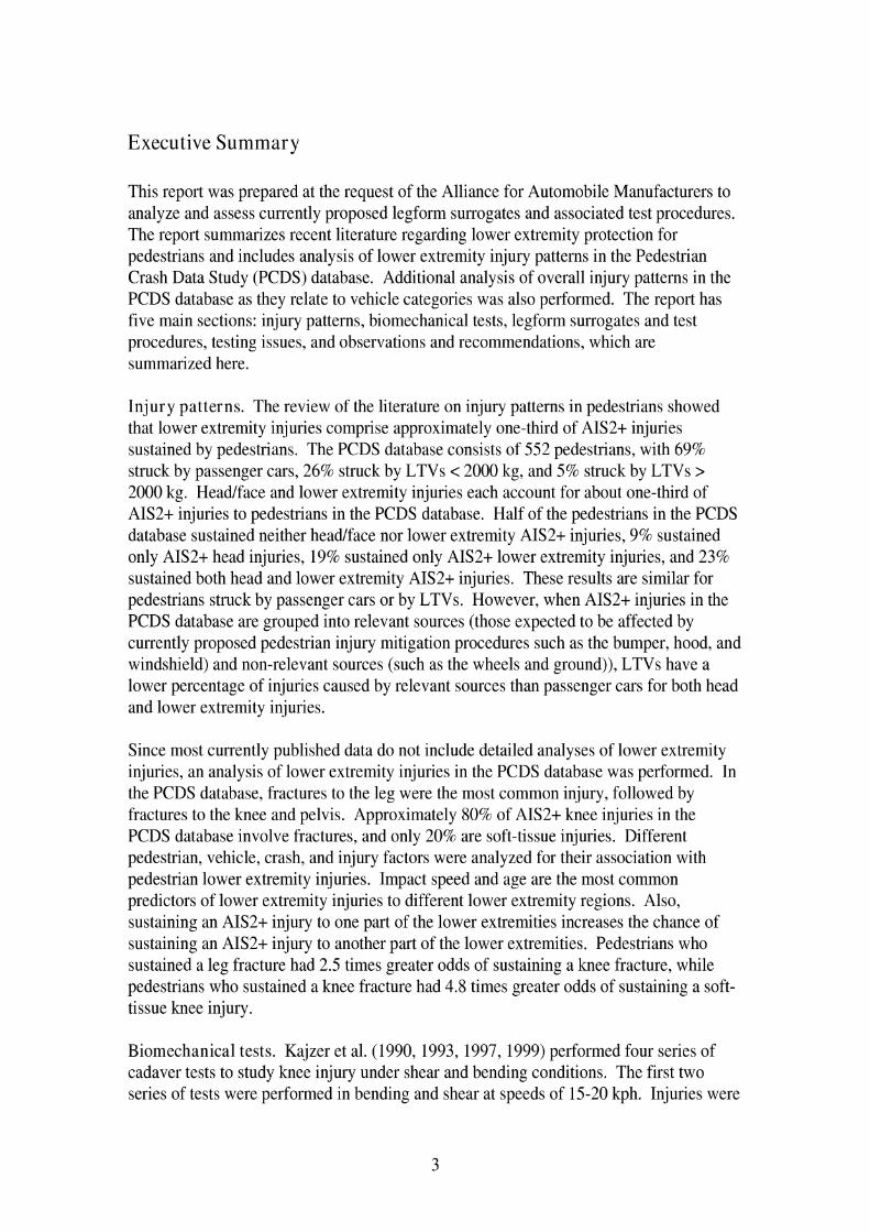
This report was prepared at the request of the Alliance for Automobile Manufacturers to analyze and assess currently proposed legform surrogates and associated test procedures. The report summarizes recent literature regarding lower extremity protection for pedestrians and includes analysis of lower extremity injury patterns in the Pedestrian Crash Data Study (PCDS) database. Additional analysis of overall injury patterns in the PCDS database as they relate to vehicle categories was also performed. The report has five main sections: injury patterns, biomechanical tests, legform surrogates and test procedures, testing issues, and observations and recommendations, which are summarized here.
Injury patterns. The review of the literature on injury patterns in pedestrians showed that lower extremity injuries comprise approximately one-third of AIS2+ injuries sustained by pedestrians. The PCDS database consists of 552 pedestrians, with 69% struck by passenger cars, 26% struck by LTVs < 2000 kg, and 5% struck by LTVs > 2000 kg. Headlface and lower extremity injuries each account for about one-third of AIS2+ injuries to pedestrians in the PCDS database. Half of the pedestrians in the PCDS database sustained neither headlface nor lower extremity AIS2+ injuries, 9% sustained only AIS2+ head injuries, 19% sustained only AIS2+ lower extremity injuries, and 23% sustained both head and lower extremity AIS2+ injuries. These results are similar for pedestrians struck by passenger cars or by LTVs. However, when AIS2+ injuries in the PCDS database are grouped into relevant sources (those expected to be affected by currently proposed pedestrian injury mitigation procedures such as the bumper, hood, and windshield) and non-relevant sources (such as the wheels and ground)), LTVs have a lower percentage of injuries caused by relevant sources than passenger cars for both head and lower extremity injuries.
Since most currently published data do not include detailed analyses of lower extremity injuries, an analysis of lower extremity injuries in the PCDS database was performed. In the PCDS database, fractures to the leg were the most common injury, followed by fractures to the knee and pelvis. Approximately 80% of AIS2t knee injuries in the PCDS database involve fractures, and only 20% are soft-tissue injuries. Different pedestrian, vehicle, crash, and injury factors were analyzed for their association with pedestrian lower extremity injuries. Impact speed and age are the most common predictors of lower extremity injuries to different lower extremity regions. Also, sustaining an AIS2+ injury to one part of the lower extremities increases the chance of sustaining an AIS2+ injury to another part of the lower extremities. Pedestrians who sustained a leg fracture had 2.5 times greater odds of sustaining a knee fracture, while pedestrians who sustained a knee fracture had 4.8 times greater odds of sustaining a soft- tissue knee injury.
Biomechanical tests. Kajzer et al. (1990, 1993? 1997, 1999) performed four series of cadaver tests to study knee injury under shear and bending conditions. The first two series of tests were performed in bending and shear at speeds of 15-20 kph. Injuries were
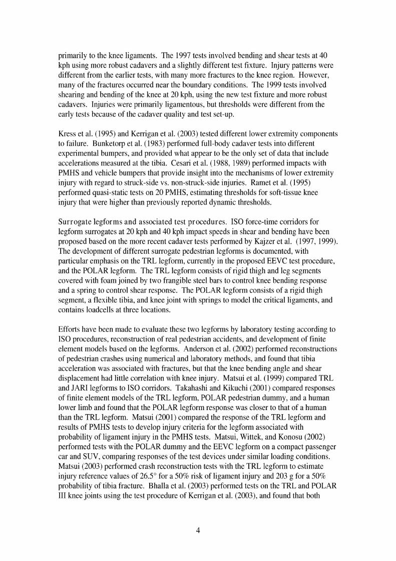
primarily to the knee ligaments. The 1997 tests involved bending and shear tests at 40 kph using more robust cadavers and a slightly different test fixture. Injury patterns were different from the earlier tests, with many more fractures to the knee region. However, many of the fractures occurred near the boundary conditions. The 1999 tests involved shearing and bending of the knee at 20 kph, using the new test fixture and more robust cadavers. Injuries were primarily ligamentous, but thresholds were different from the early tests because of the cadaver quality and test set-up.
Kress et al. (1995) and Kerrigan et al. (2003) tested different lower extremity components to failure. Bunketorp et al. (1983) performed full-body cadaver tests into different experimental bumpers, and provided what appear to be the only set of data that include accelerations measured at the tibia. Cesari et al. (1988, 1989) performed impacts with PMHS and vehicle bumpers that provide insight into the mechanisms of lower extremity injury with regard to struck-side vs. non-struck-side injuries. Ramet et al. (1995) performed quasi-static tests on 20 PMHS, estimating thresholds for soft-tissue knee injury that were higher than previously reported dynamic thresholds.
Surrogate legforms and associated test procedures. IS0 force-time corridors for legform surrogates at 20 kph and 40 kph impact speeds in shear and bending have been proposed based on the more recent cadaver tests performed by Kajzer et al. (1997, 1999). The development of different surrogate pedestrian legforms is documented, with particular emphasis on the TRL legform, currently in the proposed EEVC test procedure, and the POLAR legform. The TRL legform consists of rigid thigh and leg segments covered with foam joined by two frangible steel bars to control knee bending response and a spring to control shear response. The POLAR legform consists of a rigid thigh segment, a flexible tibia, and knee joint with springs to model the critical ligaments, and contains loadcells at three locations.
Efforts have been made to evaluate these two legforms by laboratory testing according to IS0 procedures, reconstruction of real pedestrian accidents, and development of finite element models based on the legforms. Anderson et al. (2002) performed reconstructions of pedestrian crashes using numerical and laboratory methods, and found that tibia acceleration was associated with fractures, but that the knee bending angle and shear displacement had little correlation with knee injury. Matsui et al. (1999) compared TRL and JAR1 legforms to I S 0 corridors. Takahashi and Kikuchi (2001) compared responses of finite element models of the TRL legform, POLAR pedestrian dummy, and a human lower limb and found that the POLAR legform response was closer to that of a human than the TRL legform. Matsui (2001) compared the response of the TRL legform and results of PMHS tests to develop injury criteria for the legform associated with probability of ligament injury in the PMHS tests. Matsui, Wittek, and Konosu (2002) performed tests with the POLAR dummy and the EEVC legform on a compact passenger car and SUV, comparing responses of the test devices under similar loading conditions. Matsui (2003) performed crash reconstruction tests with the TRL legform to estimate injury reference values of 26.5" for a 50% risk of ligament injury and 203 g for a 50% probability of tibia fracture. Bhalla et al. (2003) performed tests on the TRL and POLAR I11 knee joints using the test procedure of Kerrigan et al. (2003), and found that both

legforms had stiffer knee joints than the PMHS. Ishikawa et al. (2003) performed tests with the TRL legform and POLAR dummy using a pedestrian-friendly compact car, and found differences in kinematics and measured response between the dummy and legform.
Testing issues. Several important issues relevant to pedestrian legform and test procedure development have been explored through laboratory testing and computer modeling. Issues addressed include the effects of deformable tibias, presence of upper body mass, presence of an ankle joint, and ground friction. Other issues of significance reviewed in this section include methods of developing appropriate injury criteria for preventing ligamentous and bony knee injuries.
Konosu, Ishikawa, and Takahashi (2001) used computer models to show that acceleration varies differently along the length of a tibia when deformable and rigid leg shafts are used. They also developed injury risk curves for shearing displacement, bending angle, and tibia acceleration based on PMHS tests reported in the literature. Takahashi and Kikuchi (2001) used FEM of the TRL legform, POLAR dummy, and human lower limb to show how tibia rigidity, presence of upper body mass, and presence of an ankle joint affect shearing displacement and bending angle. They also suggest a combined knee bending angle vs. shearing displacement criteria for ligament injury. Bermond et al. (1994) and Janssen (1996) discuss earlier work that led to the choice of component-based tests for pedestrian injury mitigation.
Observations and Recommendations. This section summarizes issues to address when choosing a pedestrian lower extremity test procedure and legform. The emphasis in test procedures on preventing ligamentous knee injury is not supported by detailed analysis of the PCDS database, or the injury patterns in cadavers found by Kajzer et. a1 in tests performed at 40 kph, the typical legform speed proposed for testing. While the more recent tests by Kajzer et al. on which IS0 corridors are based are improved relative to earlier tests, the frequency of injuries at the supports suggests that the test setup may not be optimal for approximating pedestrian lower extremity loading by vehicles. Test procedures should address prevention of fractures to the knee and tibia, but data to develop acceleration-based injury reference values for legforms are scarce, and use of a deformable legform to achieve more biofidelic tibia acceleration patterns should be considered. The current EEVCITRL legform does not meet IS0 corridors. Therefore, if it is to be used to assess vehicle performance relative to pedestrian lower extremity injury, alternative injury reference values that attempt to compensate for some of the legform's nonbiofidelic characteristics should be considered. Although the POLAR legform has many promising features that make it more biofidelic than the EEVCITRL legform, additional research needs to be performed on the POLAR legform, particularly in reconstructing real pedestrian accidents, before it can be considered a potential regulatory test device.

1. Introduction
This report was prepared at the request of the Alliance for Automobile Manufacturers with a primary purpose of providing a preliminary biomechanical assessment of currently proposed legform surrogates and associated test procedures. The initial draft of the report was needed before the meeting of the International Harmonized Research Activities (IHRA) Pedestrian Safety Expert Group to be held on May 28,2003 in Japan. Because of the short period of time available to conduct this review, the scope of the effort has been limited to:
1) performing a preliminary investigation and analysis of the frequencies of different types of lower extremity injuries and the vehicle and pedestrian factors associated with those injuries, and
2) performing a review of the biomechanical literature regarding lower extremity injuries to pedestrians for the purpose of determining the anthropometric and mechanical response factors that may be important to include in a surrogate leg- form test device, as well as the best correlates to predicting the potential for a vehicle causing lower extremity injuries.
This report is divided into six sections. Following this brief introduction, Section 2 includes a literature review on the injury patterns of lower extremity injuries to pedestrians and results of two separate analyses of the Pedestrian Crash Data Study (PCDS) database. The first analysis examined general injury patterns in the database, particularly with regard to how injury patterns vary with vehicle type. The second analysis examined the patterns of lower extremity injuries relative to various independent pedestrian and vehicle variables. Section 3 is a review of biomechanical data reported in the literature that have been used as a basis for developing surrogate legforms and test procedures for assessing lower extremity injury potential of different vehicle front-end designs. This review of cadaver test data also includes some discussion of estimated injury mechanisms and tolerances. Section 4 reviews proposed test procedures for reducing pedestrian lower extremity injuries, while Section 5 provides a discussion of issues that should be considered in selecting a test procedure. Section 6 provides recommendations for tasks that would provide useful input to selecting appropriate and reliable test procedures and assessment criteria for use in regulatory vehicle testing related to pedestrian lower extremity injury potential.


2. Injury Patterns
2.1 Review of Recent Literature
Review of the literature regarding patterns of lower extremity injury in pedestrian crashes was limited to data published within the last five years, as changing vehicle designs in the past decades have resulted in different patterns of pedestrian injury. The main source of pedestrian injury data in the United States is the Pedestrian Crash Data Study (PCDS) (Chidester and Isenberg, 2001). The PCDS collected data on 552 vehicle-pedestrian crashes from six sites over the period of July 1994 to December 1998. Criteria for inclusion in the study were:
1) the vehicle was moving forward at the time of impact, 2) the vehicle was a late-model-year passenger car, light truck or van, 3) the pedestrian could not be lying or sitting on the road, 4) the part of the vehicle contacted had to be previously undamaged and was
equipped by the original manufacturer, 5) the pedestrian impacts were the vehicle's only impacts, 6) the first point of contact with the pedestrian must have been forward of the top of
the A-pillar, and 7) the vehicle damage was measured within 24 hours of the crash.
From their analysis of the data, Chidester and Isenberg address the following:
Pedestrian: gender, age, stature, stature versus MAIS Vehicle: type, type versus MAIS Pre-crash factors, including pedestrian motion, pedestrian activity, driver attention, vehicle action, avoidance maneuver Crash factors, including intersection involvement, weather, lighting, pedestrian body, leg, and arm orientation, pedestrian-to-vehicle interaction, impact speed, wrap distance Injury factors, including severity, treatment, MAIS, body regions injured, body region injured excluding flesh injuries, source of injury versus AIS level, source of injury versus most frequent injuries, MAIS versus impact speed.
The ten most frequent injuries reported in order of frequency were cerebrum injury, tibia fracture, fibula fracture, loss of consciousness, pelvis fractures, rib fractures, femur fractures, humerus fractures, cervical spine injury, and lung injury. However, a more detailed analysis of lower extremity injuries was not provided by Chidester and Isenberg.
Jarrett and Saul (1998) present an analysis of the first 292 PCDS cases in comparison to results from the Pedestrian Injury Causation Study (PICS), a NHTSA database of pedestrian crashes collected during the late 1970's. In comparison to PICS, PCDS

pedestrians were more often carried than knocked down, and the bumper causes 25% of injuries compared to 15% in PICS.
A report on recent work by the IHRA pedestrian safety working group (Mizuno 2003) includes analysis of an international pedestrian crash dataset. A dataset of recent pedestrian crash data was compiled from Australia, Germany, Japan, and the US. The dataset has 1605 cases, 9463 injuries, and 3305 AIS2t injuries. As shown in Figure 1, the head and lower extremities each account for about one-third of AIS2t injuries. Results for the whole database, which includes data from the PCDS study, are similar to those of the PCDS study. However, documentation of specific pedestrian lower extremity injuries was not included.
unknown, 0.2
lower ext,
n e c k , 1.4
c h e s t , 10.3 arms, 8.2 abdomen, 5.4
Figure 1. Distribution of AIS2t injury by body region in the IHRA database (data from Mizuno 2003).
As part of a program to validate the EEVC upper legform test, Matsui, Ishikawa, and Sasaki (1998) analyzed the injury patterns of pedestrians in Japan. From 1987 to 1997, femur injuries decreased from 17% to 4% and knee injuries decreased from 10% to 1%. Chest injuries increased from 3% to 11% and leg injuries from 19% to 36%. They also showed that in cases with femurlpelvis injury, the femur/pel\~is injury was more likely to be severe if the tibidfibula had fractured, suggesting that a pedestrian-friendly bumper would minimize severity of upper lower extremity injuries.
Edwards and Green (1999) examined a database of 316 severely injured pedestrians collected from one hospital over four years. The database is skewed toward fatal cases (15.5%) and does not contain ligamentous injuries nor sources of the injuries. 65.2% received lower limb injuries and 57.9% sustained head injuries. Results include number


2.2 Analysis of PCDS data
2.2.1 Analysis of Injury Patterns in the PCDS Database
Distribution of Vehicles in PCDS Database
The PCDS database contains 552 pedestrian-vehicle impacts. The distributions of pedestrian impacts and injuries by vehicle type were examined in two ways. The first classified vehicles into five categories of passenger cars, SUVs, minivans, vans, and pick- up trucks, which generally differ by the shape of the vehicle front end. As shown in Figure 2, using this scheme, passenger cars make up 68% of impacts, with pickups and minivans the next most commonly involved vehicle types. The second method of classifying vehicles grouped the SUVs, minivans, vans and pick-ups into a light truck/van category (LTV), but divided this category into vehicles with curb weights below 2000 kg (LTV 1) and above 2000 kg (LTV 2), which allowed study of injury patterns based on vehicle mass. As shown in Figure 3 using this classification, lighter LTVs are involved in 26% of pedestrian impacts, while heavy LTVs are involved in only 5% of impacts.
Figure 2. Distribution of pedestrian impacts by vehicle type using five-category classification scheme.

Figure 3. Distribution of pedestrian impacts by vehicle type using three-category classification scheme (PC=passenger car, LTV 1 < 2000 kg, LTV 2 > 2000 kg).

Since the PCDS cases were not selected in a statistically representative manner, it is possible that the distribution of cases by vehicle type may not be representative of the vehicle fleet of the mid 1990's, or of today's vehicle fleet. Vehicle registration data were estimated from a plot on the NHTSA website and are shown with the distribution of vehicle types in the PCDS database in Figure 4. In the PCDS database, LTVs account for 31% of pedestrian impacts. This is slightly lower than the LTV proportion of 33% to 36% of the vehicle fleet registrations from 1994 to 1998, the years the PCDS database was established. The latest NHTSA data indicate that 38% of the vehicle fleet was LTVs in 2001, suggesting that it may be near 40% in 2003 and near 50% in 2015. Estimates on how pedestrian injuries may change with the changing composition of the vehicle fleet are included later in this report.
80% Passenger cars --:
PCDS Veh Reg 94 Veh Reg 98 Veh Reg 01
Figure 4. Proportion of passenger cars and LTVs in the PCDS database and by vehicle registrations.

Locations and Severities of Pedestrian Injuries
The PCDS database includes 45 10 coded injuries for the 552 pedestrians in the database. Removing AIS 1 level injuries leaves 1503 AIS 2 t injuries. The coding of ten injuries does not include the body region, so these injuries, as well as five injuries coded with an unknown severity, were not included in the analysis. The distributions of the remaining 1488 AIS2t injuries by body region and injury severity are shown in Figure 5.
Head Face Thorax Abdomen Spine Upper Extr. Lower Extr.
Injured body region
Figure 5. Number of AIS2t injuries by body region and severity.
Prior to further analysis of PCDS injuries, the data were grouped into three general body region categories. Head and face injuries were grouped together into the headlface region, the thorax, abdomen, spine (including neck), and upper extremity injuries were grouped together into the "mid" body region, and the pelvis and lower extremities were grouped into the "lower extremity" region.

Each pedestrian (n=552) was coded according to the locations of their AIS2t injuries to the headtface and lower extremity. (Injuries to the mid region were not included in some analyses since currently proposed pedestrian regulations do not specifically address this region.) Results are shown in Figure 6. Almost half of pedestrians in the database sustained neither headlface nor lower-extremity AIS2t injuries. Nine percent sustained only AIS2t headlface injuries, 19% sustained only AIS2t lower-extremity injuries, and 23% sustained both headlface and lower-extremity AIS2t injuries.
head and lower
head only, 49, 9%
none, 275, 49%
Figure 6. Counts and percentages of pedestrians who sustained different combinations of AIS2+ headlface and lower-extremity injuries.

Pedestrian Injuries by Body Region and Vehicle Type
The analysis of the location of AIS2+ injuries was repeated for different vehicle types. As shown in Figure 7, the distribution of AIS2t injury by body region combinations does not differ by vehicle type (p=0.909). The distribution is the same using the five-category vehicle classification scheme (p=.181), but is not reported here.
none head only lower extremity head and lower only extremity
Body region with AIS2+ injuries
Figure 7. Percentage of pedestrians in each vehicle class with AIS2+ injuries to different combinations of headtface and lower extremity body regions.
Figure 8 shows the distribution of 1488 individual AIS2t injuries by general body region and vehicle type. For the PCDS database, passenger cars cause the largest numbers of AIS2t injuries to all three general body regions, while pickup trucks are a distant second. When looking at all injuries, rather than an injury by body region category for each pedestrian (which includes uninjured pedestrians), there are some differences in injury patterns with vehicle class (p<.0001).
When the differences between expected and observed numbers of injuries in a category are identified as statistically significant, computation and inspection of standardized residuals are used to identify the pattern of the relationship. Standardized residuals are the differences between observed and expected number of cases in each cell divided by an estimate of the standard error. The expected number of cases in a cell is determined by multiplying row totals by column totals, and dividing by the sum of all rows and columns. Negative residuals indicate fewer observations than expected, and positive numbers indicate more observations. Larger absolute values of the standardized residuals indicate a stronger association between the categories.

Referring to Figure 8 and Table 1, pedestrians struck by passenger cars sustained fewer injuries to the mid region and more injuries to the lower extremities than expected statistically. Pedestrians struck by SUVs sustained fewer headlface injuries and more mid injuries than expected statistically. Pedestrians struck by minivans sustained more headlface injuries and fewer mid injuries than expected statistically. Pedestrians struck by vans sustained more headlface and mid injuries and fewer lower extremity injuries than expected statistically. Pedestrians struck by pickup trucks sustained more mid injuries and fewer headlface and lower extremity injuries than expected statistically.
PC S UV Minivan Van Pickup
Vehicle Type
Figure 8. Numbers of AIS2+ injuries by vehicle type and general body region.
Table 1. Cross-tabulations of observed and expected frequencies and calculated standardized residuals of number of injuries to each general body region by vehicle class (cells in bold type indicate statistically

Figure 9 and Table 2 show results after repeating this analysis using the three-category vehicle classification scheme. Differences in body region injured are also statistically significant (p<0.001). Pedestrians struck by passenger cars sustained fewer mid and more lower extremity injuries than expected statistically. Pedestrians struck by lighter LTVs sustained more mid injuries and fewer lower extremity injuries than expected statistically. Pedestrians struck by heavier LTVs sustained more head injuries and fewer lower extremity injuries than expected statistically.
headiface
Passenger cars L l v 1 L l v 2
Vehicle Type
Figure 9. Numbers of AIS2t injuries by vehicle type and general body region.
Table 2. Cross-tabulations of observed and expected frequencies and calculated standardized residuals of number of injuries to each general body region by vehicle class (cells in bold indicate statistically
Lower extremity

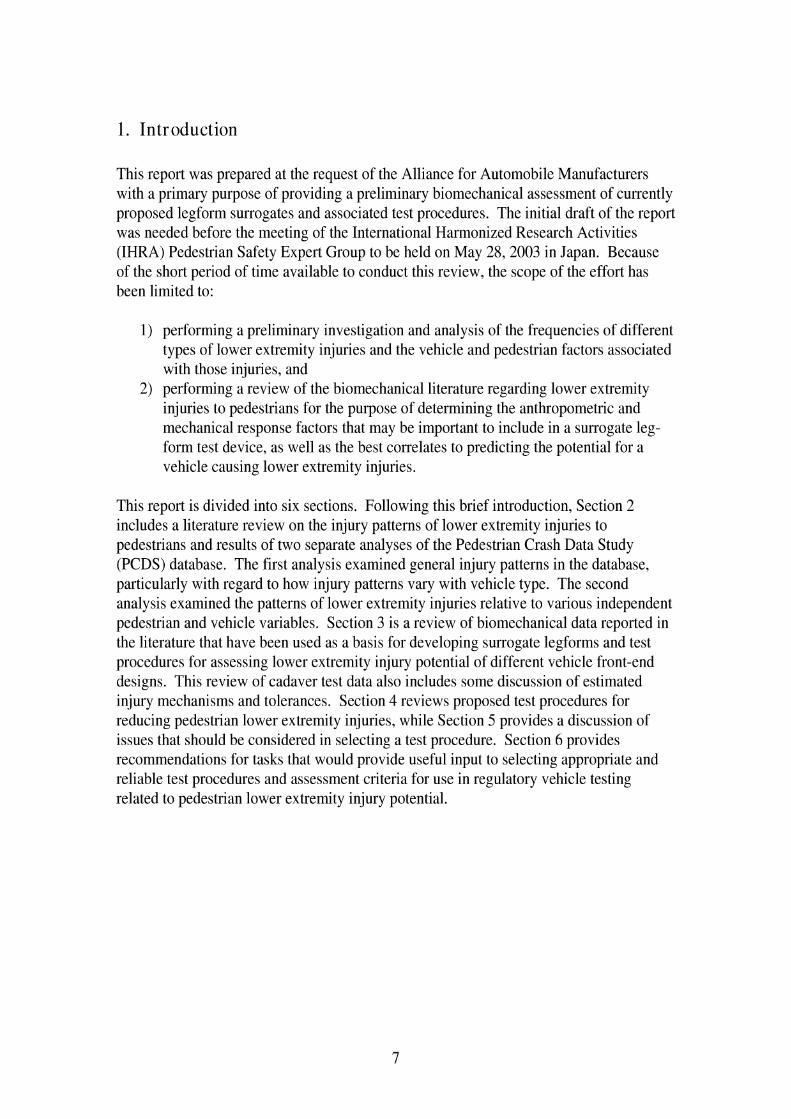
With regard to headlface AIS 2+ injuries, Figure 10 shows the percentage by vehicle type using the five-category vehicle classification scheme. Almost two-thirds of AIS2+ headlface injuries result from impacts of pedestrians by passenger cars, which is the proportion expected to occur statistically (reference Table 1). In this distribution, pedestrian impacts by SUVs and pickup trucks resulted in fewer head injuries than expected statistically, while pedestrian impacts by minivans and vans resulted in more head injuries than expected statistically. The distribution using the three-category vehicle classification scheme is shown in Figure 11. Using this distribution (reference Table 2) , the number of headlface injuries resulting from impacts by passenger cars is the proportion expected statistically, while the lighter LTVs produce fewer headlface injuries than expected and heavier LTVs produce more headlface injuries than expected.
Pickup, 78,
SUV, 30,6%\(
Figure 10. Distribution of AIS2t headlface injuries by vehicle type using the five- category classification scheme.
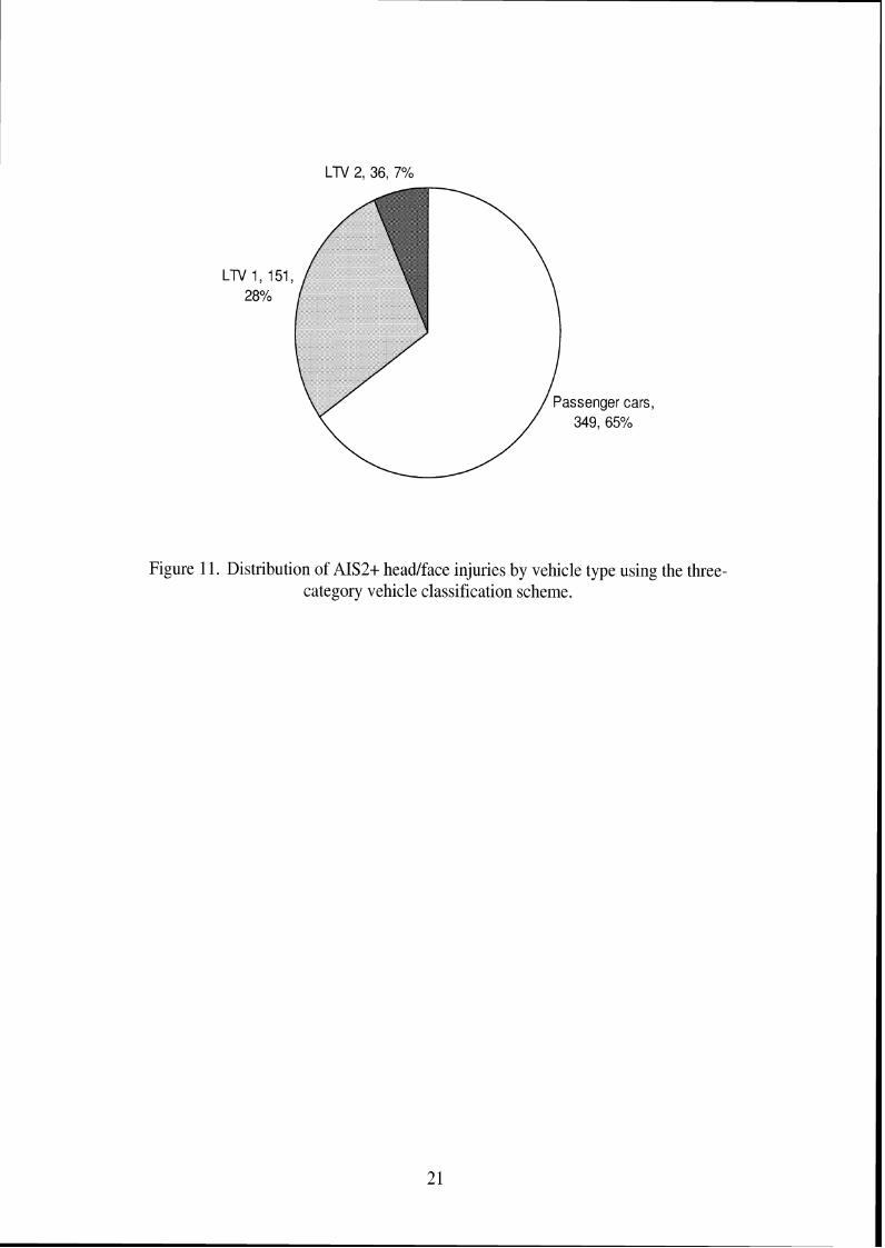
Figure 11. Distribution of AIS2t headtface injuries by vehicle type using the three- category vehicle classification scheme.

Figure 12 shows the distribution of AIS2t lower extremity injuries by vehicle type using the five-category vehicle classification scheme. Almost 75% of lower extremity injuries result from impacts by passenger cars, which is a higher proportion than expected statistically (reference Table 1). The proportions of lower extremity injuries from SUV and minivan impacts are expected statistically, while vans and pickups resulted in fewer lower extremity injuries than expected statistically. This analysis was repeated using the three-category vehicle classification scheme as shown in Figure 13. Impacts with passenger cars resulted in more lower extremity injuries than expected statistically (reference Table 2), while impacts with lighter and heavier LTVs resulted in fewer lower extremity injuries than expected statistically.
Figure 12. Distribution of AIS2t lower extremity injuries by vehicle type using the five- category vehicle classification scheme.
Passenger cars, 366, 72%
Figure 13. Distribution of AIS2t lower extremity injuries by vehicle type using the three-category vehicle classification scheme.
Severity of Injuries by Body Region and Velzicle Type
With regard to the effect of vehicle type on the severities of injuries to these grouped body regions, Table 3 shows the mean AIS for all AIS2+ injuries, AIS2+ headlface injuries, and AIS2t lower extremity injuries for the passenger car, LTV1, and LTV2 groupings. While the mean AIS score for all AIS 2 t injuries is statistically higher for the two LTV categories than the passenger car categories, the differences between passenger cars and LTVs for AIS2t headlface injuries are statistically the same. For AIS2t lower extremity injuries, the mean AIS level of injuries sustained in impacts with lighter LTVs is higher than the mean AIS level sustained from impacts by passenger cars and heavier LTVs.
1 All AIS2t injuries 1 2.82 1 2.98 1 3.04 1 0.006 1
Table 3. Mean AIS score for passenger cars and two LTV categories
I AIS2t headlface iniuries 1 3.33 1 3.44 1 3.42 1 0.559 1
Mean AIS score PC L T V I L T V ~
I AIS2t lower extremitv iniuries 1 2.41 1 2.61 1 2.40 1 0.007 1
p-value
Pedestrians b j Number of AIS2 t Injuries
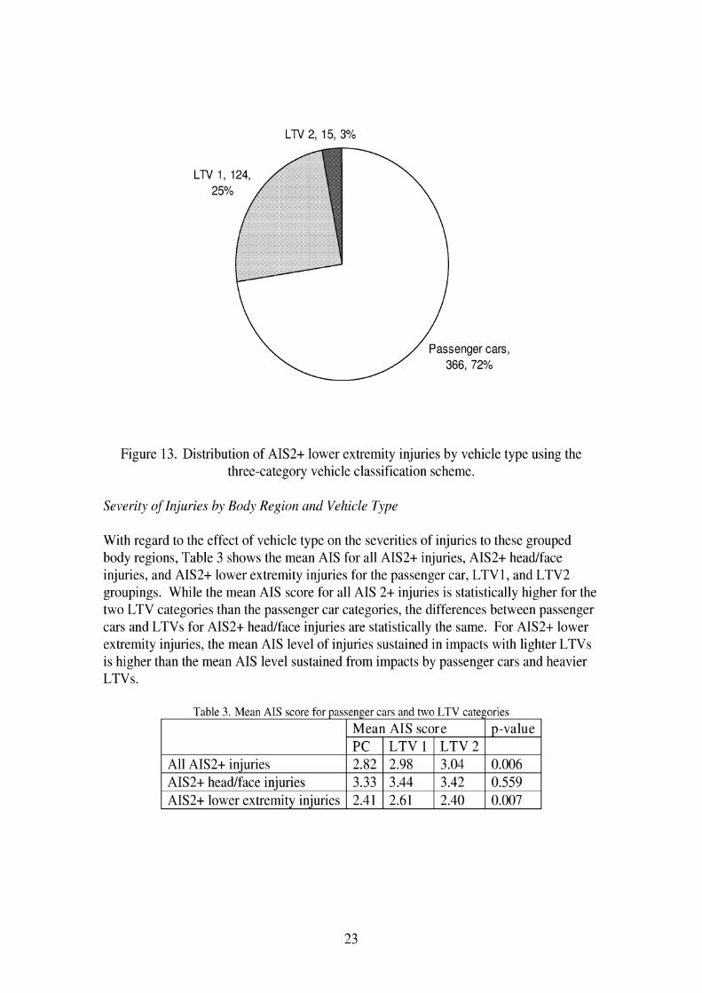
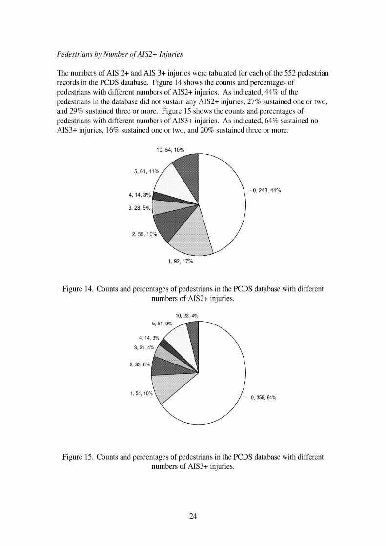
The numbers of AIS 2 t and AIS 3 t injuries were tabulated for each of the 552 pedestrian records in the PCDS database. Figure 14 shows the counts and percentages of pedestrians with different numbers of AIS2t injuries. As indicated, 44% of the pedestrians in the database did not sustain any AIS2t injuries, 27% sustained one or two, and 29% sustained three or more. Figure 15 shows the counts and percentages of pedestrians with different numbers of AIS3t injuries. As indicated, 64% sustained no AIS3t injuries, 16% sustained one or two, and 20% sustained three or more.
Figure 14. Counts and percentages of pedestrians in the PCDS database with different numbers of AIS2t injuries.
Figure 15. Counts and percentages of pedestrians in the PCDS database with different numbers of AIS3t injuries.

The counts and percentages of pedestrians with different numbers of AIS2+ and AIS3+ injuries to the whole body were compiled separately for pedestrians struck by passenger cars, lighter LTVs, and heavier LTVs. Figure 16 compares the counts of pedestrians with different numbers of AIS 2+ injuries for the three vehicle groups, while Figure 17 compares proportions of pedestrians in each group with different numbers of injuries. While the numbers of pedestrians with AIS2+ injuries from impacts with passenger cars in the database exceed the numbers with AIS2+ injuries from both LTV categories for all counts of AIS 2 t injuries, the proportions of pedestrians in each vehicle group with different counts of AIS 2+ injuries are essentially and statistically the same (p=0.924). Similar results between passenger cars and LTVs were found for AIS3t injuries, but are not presented here (p=0.580).
0 1 2 3 4 5-9 l o t
Number of AIS2t Injuries
Figure 16. Counts of pedestrians by number of AIS2+ injuries sustained in impacts with passenger cars, lighter LTVs, and heavier LTVs.
Figure 17. Proportions of pedestrians by number of AIS2+ injuries sustained in impacts with passenger cars, lighter LTVs, and heavier LTVs.
Predictors of Pedestriarz Injuries
Logistic regression analysis was performed to identify possible predictors of pedestrian AIS 2 t headlface injuries and lower-extremity injuries (the mid region was not included in this analysis). Pedestrian stature, age, gender, and impact speed were considered as potential predictors. Age and gender are the best predictors, but the fit of the model is poor. When the analysis was performed separately for impacts by passenger cars and impacts by LTVs, age is the best predictor for passenger cars and gender is best for LTVs. However, the fit of the models is very poor. Impact speed was not shown to be a predictor of AIS2+ injuries to either of these body regions.
When the presence of an AIS2t lower extremity injury was included as a potential predictor for AIS2t head injury, it was selected as the best predictor, although the fit is only slightly better than the models using gender and age. The results of this analysis indicate that pedestrians with AIS2t lower-extremity injuries have about 3.8 [95%CI:2.528:5.753] greater odds of sustaining an AIS2t headlface injury than those without an AIS2t lower-extremity injury. This indicates that pedestrians involved in crashes severe enough to result in an AIS2t injury to one body region are those most likely to sustain an AIS2+ injury in another body region.
Sources of Pedestrian Injuries
Additional analyses were performed on the AIS2t injuries relative to the source of pedestrian injuries to determine which injuries resulted from vehicle components that might be affected by regulation (such as bumpers and hood) versus injuries that resulted from non-relevant sources, such as the ground. The AIS2t injuries in the PCDS database were attributed to 35 different injury sources that were reduced to 14 groups for analysis, as shown in Table 4. While injuries attributed to components such as the ground or vehicle tireslwheels might be reduced by countermeasures that change pedestrian kinematics, these were not expected to directly result from component level countermeasures currently under consideration in regulations, and therefore were not considered to be "relevant" sources of pedestrian injuries.
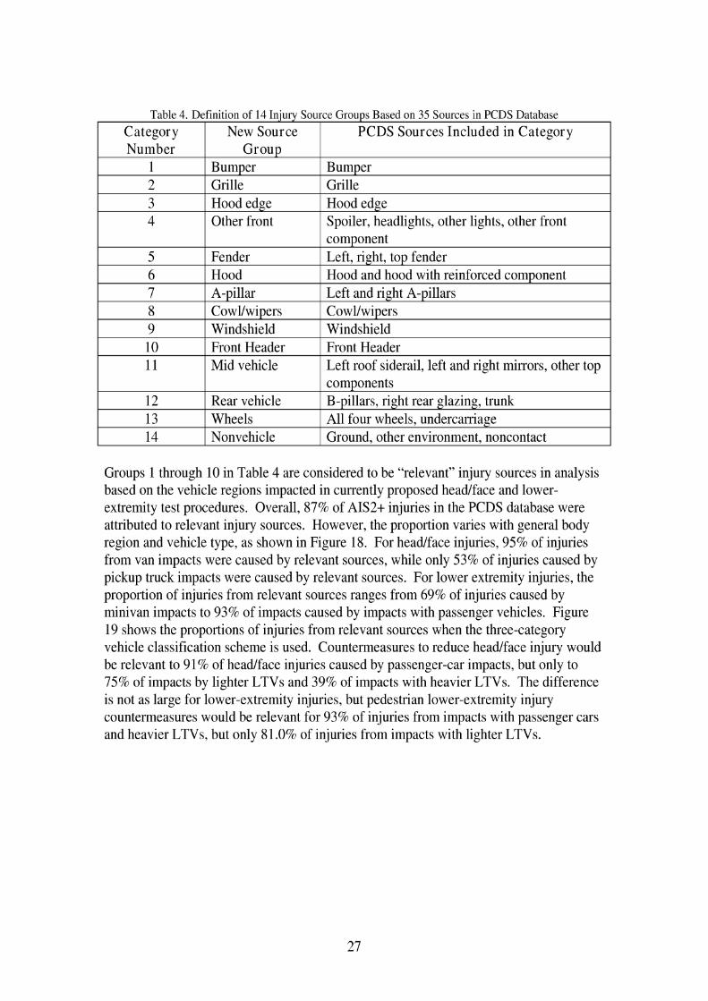
Table 4. Definition of 14 Injury Source Groups Based on 35 Sources in PCDS Database
I 1 I Bumper I Bumper I
Category Number
I 2 I Grille I Grille I
Group
3 I Hood edge I Hood edge
New Source
I 4 1 Other front 1 Spoiler, headlights, other lights, other front 1
PCDS Sources Included in Category
I 9 I Windshield I Windshield I
5 6 7
I 10 I Front Header I Front Header I 1 11 1 Mid vehicle 1 Left roof siderail, left and right mirrors, other top I
Fender Hood A-pillar
component Left, right, top fender Hood and hood with reinforced component Left and right A-pillars
14 1 Nonvehicle 1 Ground, other environment, noncontact
12 13
Groups 1 through 10 in Table 4 are considered to be "relevant" injury sources in analysis based on the vehicle regions impacted in currently proposed headlface and lower- extremity test procedures. Overall, 87% of AIS2t injuries in the PCDS database were attributed to relevant injury sources. However, the proportion varies with general body region and vehicle type, as shown in Figure 18. For headlface injuries, 95% of injuries from van impacts were caused by relevant sources, while only 53% of injuries caused by pickup truck impacts were caused by relevant sources. For lower extremity injuries, the proportion of injuries from relevant sources ranges from 69% of injuries caused by minivan impacts to 93% of impacts caused by impacts with passenger vehicles. Figure 19 shows the proportions of injuries from relevant sources when the three-category vehicle classification scheme is used. Countermeasures to reduce headlface injury would be relevant to 91% of headlface injuries caused by passenger-car impacts, but only to 75% of impacts by lighter LTVs and 39% of impacts with heavier LTVs. The difference is not as large for lower-extremity injuries, but pedestrian lower-extremity injury countermeasures would be relevant for 93% of injuries from impacts with passenger cars and heavier LTVs, but only 81.0% of injuries from impacts with lighter LTVs.
Rear vehicle Wheels
components B-pillars, right rear glazing, trunk All four wheels, undercarriage

Headlface Mid Lower extr
Body region injured
Figure 18. Proportion of AIS2+ injuries to three body-region groups attributed to "relevant" injury sources by vehicle type.
Headlface Mid Lower extr
Body region injured
Figure 19. Proportion of AIS2t injuries to the three body-region groups attributed to relevant injury sources for passenger cars and LTVs.

Estimate of changing pedestrian injury patterns with vehicle fleet changes
The previous analysis of pedestrian injury patterns was based on a database in which 3 1 % of the pedestrian impacts were by LTVs. The proportion of vehicles in the 2003 fleet that are LTVs is estimated to be 40%, and the increasing market share of LTVs suggests that the vehicle fleet could be 50% LTVs within the next fifteen years. These proportions are compared in Figure 20.
PCDS 2003 (est.) Future: 50% LTV
Figure 20. Proportion of vehicle fleet by vehicle type in PCDS database, 2003, and future.
An analysis was performed to estimate how pedestrian injury patterns might be expected to change if the vehicle fleet was comprised of 40% or 50% LTVs. Because the analysis pedestrians according to body region with AIS2t injuries (headlface, lower extremity, both, or neither in Figure 6) do not show statistically significant differences for between passenger cars and LTVs, these results are not expected to change. However, when looking at injuries sustained by pedestrians (excluding pedestrians without AIS2+ headlface or lower extremity injuries), there is some difference in headlface and lower extremity injury patterns with vehicle type. Figure 21 shows an estimate of the proportion of AIS2t headlface injuries that would be expected to result with LTVs making up 40% and 50% of the vehicle fleet. As the vehicle fleet shifts towards equal numbers of passenger cars and LTVs, LTVs will cause more head injuries than passenger cars. However, headlface injuries caused by relevant sources should also be considered, as this varies considerably with vehicle type for head injuries. The figure also indicates with an X the number of injuries caused by relevant sources. When the vehicle fleet reaches 50% LTVs, although the proportion of headlface injuries caused by LTVs will be

higher than that caused by passenger vehicles, the proportion of headlface injuries caused by relevant sources will still be higher for passenger cars.
Figure 21. Proportion of headlface injuries caused by PCs and LTVs.
Figure 22 shows similar calculations for AIS2t lower extremity injuries. When the vehicle fleet reaches 50% LTVs, passenger cars will still cause slightly more lower extremity injuries, although the difference is not as great as in the PCDS database. The proportion of lower extremity injuries caused by relevant sources will remain higher for passenger cars, but because passenger cars and LTVs have similar levels of injuries caused by relevant sources, the differences for lower extremities are not as large as for headlface injuries.
PCDS 3% hW 2003 jest b 93% ~ b f t . Future 5Q4h i.TtJ
Figure 22. Proportion of lower extremity injuries caused by PCs and LTVs.

S u m m a v of PCDS I n j u v Patterns
Pedestrian-passenger car impacts make up 69% of PCDS cases, while lighter LTVs make of 26% of cases and heavier LTVs make up 5% of cases. In today's vehicle fleet, the total proportion of LTVs is estimated to be 40%. Headlface and lower extremity injuries each account for about one- third of AIS2+ injuries to pedestrians in the PCDS database. Half of the pedestrians in the PCDS database sustained neither headlface nor lower extremity AIS2+ injuries, 9% sustained only AIS2t head injuries, 19% sustained only AIS2t lower extremity injuries, and 23% sustained both head and lower extremity AIS2t injuries. These results are similar for pedestrians struck by passenger cars or by lighter and heavier LTVs. In the PCDS database of pedestrian impacts, collected from 1994 through 1998,64% of AIS2t headlface injuries and 73% of lower extremity injuries result from impacts from passenger cars. In the PCDS database, 44% of pedestrians struck by vehicles do not sustain anyAIS2t injuries, 17% sustain only one AIS2t injury, and the 39% sustain multiple AIS2t injuries. In the PCDS database, 64% of pedestrians struck by vehicles do not sustain any AIS3t injuries, 10% sustain only one AIS3t injury, and 26% sustain multiple AIS3t injuries. The distribution of the number of AIS 2 t injuries sustained by pedestrians struck by LTVs is similar to the distribution of the number of AIS 2 t injuries for pedestrians struck by passenger cars. The average severity of AIS2t headlface injuries are statistically the same for pedestrians struck by passenger cars and LTVs, but the average severity of lower extremity injuries is higher for lighter LTVs than passenger cars or heavy LTVs. Impact speed, gender, age, and stature are not good predictors of the likelihood of a pedestrian sustaining AIS2t headlface or lower- extremity injuries. Pedestrians with AIS2t lower extremity injuries have 3.8 times greater odds of sustaining and AIS2+ head injury. 87% of AIS2t injuries in the PCDS database are attributed to injury sources expected to be affected by currently proposed pedestrian injury mitigation procedures such as the bumper, hood, and windshield, but this proportion varies with vehicle body type. For AIS2t headlface injuries, 91% are caused by relevant sources on passenger cars, while only 75% are caused by relevant sources on lighter LTVs and 39% aar caused by relevant sources on heavier LTVs. For AIS2t lower extremity injuries, 93% result from relevant sources on passenger cars and heavier LTVs, while 8 1 % result from relevant sources on lighter LTVs.

2.2.2 Analysis of all lower extremity injuries
Because recent publications did not include a detailed analysis of pedestrian lower extremity injuries, an analysis of the PCDS database was performed with a focus on lower extremity injuries. The final database consists of 552 crashes, of which 203 pedestrians sustained 509 AIS2t lower extremity injuries. In this analysis, the lower extremity injuries were classified as shown in Table 5 using a functional classification rather than a strictly anatomic classification. For example, fractures to the tibial malleolus were included in the anklelfoot category, and fractures to the tibial plateau were included in the knee fracture category. Knee soft-tissue injuries were grouped separately from the knee fracture injuries. Injuries to the pelvis are included with the lower extremity rather than as a separate body region. Table 5 includes all of the types of injuries found in the PCDS database.
Table 5. Classifications of lower extremity injuries in the PCDS database.
Figure 23 and Figure 24 show the counts of AIS 2 and AIS 3 t lower extremity injuries in the PCDS database by body region. The most frequent types of injuries are labeled on the plots. Among AIS 2 injuries, fractures to the leg (i.e. mid-shaft of tibia and fibula) are most frequent, followed by knee injuries. Approximately 45% of AIS 2 knee injuries
Category Anklelfoot
Tibidfibula shaft
Knee fractures
Knee soft tissues
Femur shaft
Hip
Pelvis
Whole lower extremity
AIS 2 Injuries Dislocation Foot fracture Fibula lateral malleolus fracture Tibia fracture Fibula fracture
Femoral condyle fracture Patella fracture Tibia1 condyle fracture Tibial plateau fracture Joint laceration Dislocation Ligament laceration Sprain Femur fractures < 12Y0 Femoral vessel injury
Femoral headlneck fracture < 12YO Pelvis fractures
Compartment syndrome Laceration
AIS 3 t Injuries
Amputation below knee Tibia openlcomminuted fracture Tibia1 condyle fracture Tibia1 plateau fracture Femoral condyle fracture
Ligament laceration
Femur fracture Femoral vessel injury Amputation above knee Femoral headlneck fractures
Pelvis fracture Sacroilium fractures Pubic symphysis fractures Degloving

are soft-tissue injuries. For AIS3+ injuries, fractures to the leg are also the most frequent type, followed by injuries to the pelvislhip. Figure 25 shows the distribution of all AIS2+ lower extremity injuries in the PCDS database. These results show that fractures to the leg are most frequent, followed by knee and pelvislhip injuries, which comprise almost the same proportion of all lower extremity injuries.
PCDS AIS 2 Lower Extremity Injuries
footiankle leg shaft knee thigh pelvislhip general
Figure 23. AIS 2 lower extremity injuries in the PCDS database by body region.
PCDS AIS 3 t Lower Extrem~ty Injur~es
120 ;
footiankle leg shaft knee thigh pelvislhip general
Figure 24. AIS 3+ lower extremity injuries in the PCDS database by body region.

PCDS AIS 2 t Lower Extremity Injuries
footiankle leg shaft knee thigh pelvislhip general
Figure 25. AIS 2 t lower extremity injuries in the PCDS database by body region.
Figure 26 through Figure 28 show the breakdown of AIS2t lower extremity injuries by body region according to gender, age group, and vehicle body type. For each plot, the overall distribution of pedestrians in the database is shown in the last column. Figure 26 shows that men and women generally have the same lower extremity injury patterns, although men sustain a greater proportion of leg and unspecified injuries. Figure 27 shows that children aged 0 to 15 sustain fewer lower extremity injuries than expected in every category except for thigh injuries. Pedestrians over age 60 have a disproportionately high frequency of anklelfoot injuries. When reviewing injuries according to vehicle type in Figure 28, pedestrians struck by vans have a greater proportion of anklelfoot injuries, while those struck by SUVs have a greater proportion of thigh and pelvislhip injuries.
I Female
Male
Anklelfoot Leg shafl Knee Thigh PeldsiHip Unspecified Total Overall dist
Figure 26. AIS2+ lower extremities in the PCDS database by gender and body region.

Anklelfoot Leg shafi Knee n i g h Pel\lis/Hip Unspecified Total Overall dist
Figure 27. AIS2+ lower extremities in the PCDS database by age group and body region.
P~ckup
M~n~van
H SUV
car
Anklelfoot Leg shaft Knee migh PelvisiHip Unspecified Total Overall dist
Figure 28. AIS2+ lower extremities in the PCDS database by vehicle body type and body region.

Some pedestrians sustain more than one AIS2t injury to the struck-side lower extremity. Figure 29 shows the number of AIS2+ lower-extremity injuries per occupant by vehicle body type. Pedestrians struck by a pickup are more likely to sustain multiple injuries than are those struck by passenger cars.
pickups
vans
I suv passenger car
0 1 2 3 4-6
Number of AIS2t lower extremity injuries
Figure 29. Distributions of the count of AIS2+ lower extremity injuries by vehicle body tY Pee
2.2.3 Factors related to lower extremity injuries on the struck side
After the analysis of all AIS2t lower extremity injuries in the PCDS database, a more detailed analysis of the database with regard to factors associated with different lower extremity injuries and the relationships between the occurrence of different types of lower extremity injuries was performed. A goal of the analysis was to investigate whether the presence of one type of lower extremity injury affected the likelihood of another type of lower extremity injury occurring. For example, does a tibia fracture suggest that a femur fracture is more or less likely? This analysis was complicated by the presence of AIS2t injuries on both lower extremities for some pedestrians. Since a tibia fracture to the right leg is expected to have little effect on the likelihood of femur fracture to the left leg, using all lower extremity injuries for each pedestrian was considered inappropriate for this analysis, so an effort was made to restructure the dataset to consider only lower extremity injuries occurring on the struck side.
To identify the struck-side injuries, the locations of each pedestrian's lower extremity injuries were analyzed and compared to the pedestrian's coded body orientation relative to the striking vehicle. For pedestrians coded with unknown, front-facing, or rear-facing body postures, the lower extremity with the most severe injuries was assumed to be on
the struck side. Pelvis injuries were coded on the struck side unless they occurred to both the left and right sides or were specified as being on the nonstruck side.
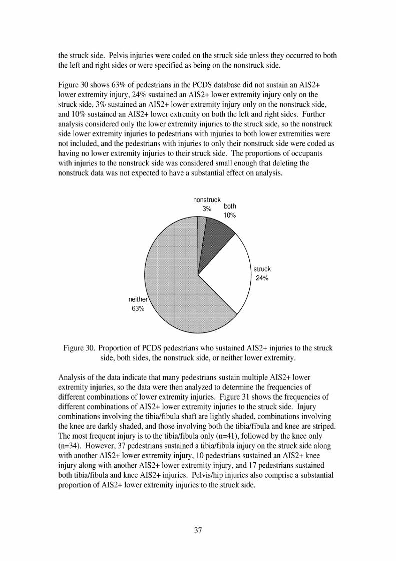
Figure 30 shows 63% of pedestrians in the PCDS database did not sustain an AIS2t lower extremity injury, 24% sustained an AIS2t lower extremity injury only on the struck side, 3% sustained an AIS2t lower extremity injury only on the nonstruck side, and 10% sustained an AIS2t lower extremity on both the left and right sides. Further analysis considered only the lower extremity injuries to the struck side, so the nonstruck side lower extremity injuries to pedestrians with injuries to both lower extremities were not included, and the pedestrians with injuries to only their nonstruck side were coded as having no lower extremity injuries to their struck side. The proportions of occupants with injuries to the nonstruck side was considered small enough that deleting the nonstruck data was not expected to have a substantial effect on analysis.
nonstruck 3% both
struck 24%
Figure 30. Proportion of PCDS pedestrians who sustained AIS2t injuries to the struck side, both sides, the nonstruck side, or neither lower extremity.
Analysis of the data indicate that many pedestrians sustain multiple AIS2t lower extremity injuries, so the data were then analyzed to determine the frequencies of different combinations of lower extremity injuries. Figure 3 1 shows the frequencies of different combinations of AIS2t lower extremity injuries to the struck side. Injury combinations involving the tibialfibula shaft are lightly shaded, combinations involving the knee are darkly shaded, and those involving both the tibialfibula and knee are striped. The most frequent injury is to the tibialfibula only (n=41), followed by the knee only (n=34). However, 37 pedestrians sustained a tibialfibula injury on the struck side along with another AIS2t lower extremity injury, 10 pedestrians sustained an AIS2t knee injury along with another AIS2+ lower extremity injury, and 17 pedestrians sustained both tibialfibula and knee AIS2t injuries. Pelvislhip injuries also comprise a substantial proportion of AIS2+ lower extremity injuries to the struck side.

Number of pedestrians with AIS2t lower extremity injuries to struck side
t'of'b on y I 141
anklefoot and tibfib 1 1 19
tibfib and pelvis 1 3 10 KEY: tibfib and anklefoot and pelvis 1 4 light: involves tibfib
tibf~b and other combo 1 4 striped: involves tibfib and knee dark: involves knee
tibfib and knee '1 11 white: involves neither knee nor tibfib
tibfib and knee and pelvis -1 6
knee only 34 1 1
10 knee and other combo j
anklefoot and pelvis 2 I I
anklefoot only 1 7 10 I 1 femur only -1 9
femur and pelvis 17 9 I 1 pelvis-hip only 1 1 20 j
I i
Figure 3 1. Counts of AIS2t lower extremity injuries by combinations of different injury regions.
The data were further analyzed to examine the correspondence of AIS2t lower extremity injuries to the struck side with pedestrian age, gender, and stature, bumper heights, ratio of pedestrian knee height to bumper height, vehicle body type, impact speed, and vehiclelpedestrian interaction.
For the continuous variables of impact speed, pedestrian stature, pedestrian age, bumper height (top and bottom), and knee heightltop bumper height, ANOVA analysis was performed to determine if the mean values are significantly different between the pedestrians with and without AIS2t lower extremity injuries to the struck side. Results shown in Table 6 indicate the mean values for all of these variables are statistically different for pedestrians with and without AIS2+ lower extremity injuries to the struck side. Pedestrians with AIS2+ lower extremity injuries to the struck side tend to be older and taller than those without lower extremity injuries. Also, having higher impact speed, higher bumper heights, and a higher kneelbumper height ratio correspond to a greater likelihood of sustaining an AIS2t lower extremity injury to the struck side.

Table 6. Mean values of crash and pedestrian factors for cases with and without AIS2t lower extremity injuries to the struck side
The comparison of mean values of crash and pedestrian factors was repeated for cases with and without AIS2t knee fracture injuries, knee soft-tissue injuries, and tibialfibula shaft injuries to the struck side. Table 7 shows that for cases with and without knee fracture, only the mean values of pedestrian age and stature were statistically different at a pc.05 level. For the analysis of cases with and without knee soft-tissue injuries shown in Table 8, none of these factors were statistically different. Regarding cases with and without tibialfibula shaft fractures presented in Table 9, impact speed, pedestrian age and stature, and knee heightbumper height ratio were statistically different.
Table 7. Mean values for of crash and pedestrian factors for cases with and without AIS2t knee fractures to the struck side
I AIS 2 t Knee fracture I I without I with I D-value I
I Bottom b u m ~ e r height 1 31.3 1 35.9 1 0.059 1
Impact speed Pedestrian age
Pedestrian stature
I Toz, bumper height 1 44.5 1 49.6 1 0.120 1
Table 8. Mean values of crash and pedestrian factors for cases with and without AIS2t knee soft-tissue iniuries to the struck side
28.0 33.0
160.5
I AIS2t Knee soft-tissue iniurv I I without I with I D-value I
33.2 49.1
169.2
I Impact speed 1 28.4 1 29.1 1 0.873 1
0.142 0.000
0.013
I Pedestrian ape 1 34.2 1 38.5 1 0.389 1 I Pedestrian stature 1 160.9 1 168.6 1 0.105 1 I Bottom bumper h e i ~ h t 1 31.6 1 34.4 1 0.435 1
Top bumper height kneehtltopbumperht
44.8 1.5
48.6 1.4
0.435 0.387

Table 9. Mean values of crash and pedestrian factors for cases with and without AIS2t tibidfibula shaft fractures to the struck side
To further investigate the relationship of impact speed to AIS2+ lower extremity injuries on the struck side, the number of cases with and without AIS2+ lower extremity injuries to the struck side was calculated for eight different speed ranges. These counts were divided by the total number of cases with or without AIS2t lower extremity injuries to the struck side. Results are shown in Figure 32 and show distinctly different patterns of impact speeds for pedestrians with and without AIS2+ lower extremity injuries. Pedestrians without lower extremity injury are more likely to be struck be a vehicle traveling less than 30 krnlh and very few pedestrians without lower extremity injuries were struck at impact speeds greater than 40 k d h .
Impact speed (kph)
Figure 32. Proportion of pedestrians with and without AIS2+ lower extremity injuries to the struck side by impact speed.

A similar analysis was performed for pedestrian age as illustrated in Figure 33. Up to age 30, the proportion of cases without AIS2t lower extremity injuries to the struck side exceeds the proportion of cases with AIS2t lower extremity injuries to the struck side. After age 30, the reverse holds. The difference is greatest in the 71-80 year age range, which makes up 13.5% of the injury cases and just over 4% of the non-injury cases. Figure 34 shows these data cumulatively.
Pedestrian age (year)
Figure 33. Proportion of pedestrians with and without AIS2t lower extremity injuries to the struck side by pedestrian age.
Age group
Figure 34. Cumulative proportion of pedestrians with and without AIS2t lower extremity injuries to the struck side by pedestrian age.

The proportion of pedestrians in each stature group was calculated for those with and without lower extremity injuries to the struck side. The stature differences shown in Figure 35 are not as large, but the greatest proportion of non-injury cases is the 161-170 stature group, while the greatest proportion of injury cases is the 17 1-1 80 cm stature group.
Pedestrian stature (cm)
Figure 35. Proportion of pedestrians with and without AIS2t lower extremity injuries to the struck side by pedestrian stature.
Other crash factors examined for their association with the occurrence of lower extremity injury are gender, vehicle type, and vehiclelpedestrian interaction. As shown in Figure 36 and Figure 37, the proportions of malelfemale and different vehicle body types were essentially the same for pedestrian crashes with and without AIS2t lower extremity injuries to the struck side. There are, however, some differences in vehiclelpedestrian interaction, shown in Figure 38. Pedestrians with AIS2t lower extremity injuries to the struck side are more likely to be wrapped around the vehicle, while those without injury were more likely to be knocked down or pushed aside.

without with
Struck-side AIS2t lower extremity injur ies
I female
male
Figure 36. Pedestrians with and without AIS2+ lower extremity injuries to the struck side by pedestrian gender.
pickup
van
S uv pass. cars
without with
Struck-side AIS2t lower extremity injuries
Figure 37. Pedestrians with and without AIS2t lower extremity injuries to the stmck side by vehicle body type.

without LEinj
wrapped thrown forward knocked down pushed aside other
Pedestrianivehicle interaction
Figure 38. Pedestrians with and without AIS2t lower extremity injuries to the struck side by vehiclelpedestrian interaction.
To further analyze the relationships of different crash and pedestrian factors with AIS2t lower extremity injuries to the struck side, logistic regression analysis was performed. Results are summarized in Table 10. This analysis was performed using a forward Wald regression technique. Factors considered to be potential predictors are impact speed, pedestrian stature, age, and gender. In addition, the presence or absence of an AIS2t lower extremity distal to the injury being examined was considered a potential predictor, based on the hypothesis that more distal lower extremity injuries tend to occur before those to the proximal end. For example, when looking at potential predictors of knee injury, presence or absence of anklelfoot injury and leg shaft injury were considered to be potential predictors. Time did not permit further logistical analysis using vehicle factors (such as bumper height) as potential predictors.
These regression analyses should be used with caution, because although the variables shown are statistically significant predictors of the dependent variable, the logistic function may not be the best model to use in some cases. For example, some of the functions show a significant risk at very low impact speeds. This may partly result from the limited amount of data, or be complicated by different mechanisms of lower extremity injury. For example, some lower extremity injuries may not be caused by the vehicle, but by contact with the ground. It may be reasonable for a 70-year-old to have a 20% risk of lower extremity injury at impact speeds of 2 kph if falling mechanisms are considered.


The factors shown to be the best predictors of different AIS2+ lower extremity injuries to the struck side are summarized in Table 11. Impact speed was predictive of all dependent variables considered except for knee fracture and knee soft-tissue injury. Age is a predictor of lower extremity injury, anklelfoot injury, knee fracture, and pelvislhip injury. Stature is only a predictor for thigh injury, while gender is only a predictor for pelvislhip fracture. Anklelfoot injury is associated with leg shaft injury, while leg shaft fracture is associated with knee fracture and thigh injury. The only variable predictive of knee soft-tissue injury is knee fracture. Thigh fracture is associated with pelvislhip injury.
Table 1 1. Predictors for different types of AIS2+ lower extremity injuries to the struck side
AIS2t lower extremity Injury AIS2t ankle1 foot injury AIS2t leg shaft injury AIS2t knee fracture AIS2t knee soft- tissue injury AIS2t thigh injury AIS2t pelvislhip injury
Impact speed
x
x
x
x x
Age
x
x
x
x
Stature
x
Gender
x
Anklelfoot injury
x
Tiblfib injury
x
x
Knee fracture
x
Thigh fracture
x

Figure 39 shows the probability of AIS2t lower extremity injuries to the pedestrian's struck side by impact speed and pedestrian age. Curves are shown for 10-year-old, 40- year-old, and 70-year-old pedestrians. Risk of injury increases with increasing impact speed, as does increasing age. The 50% probability of injury is at 57 k d h for a 10-year- old, 42 k d h for a 40-year-old, and 27 k d h for a 70-year-old.
5 25 45 65 85 105
Impact speed (kph)
Figure 39. Probability of AIS2t lower extremity injuries to the struck side by impact speed and pedestrian age.
Logistic regression plots for anklelfoot injury, knee fracture, and knee soft-tissue do not have a shape indicative of a good fit using the logistic model and are not included in the report. However, some points of interest from Table 10 regarding these dependent variables are included here. The odds ratio for knee fracture suggests that pedestrians who sustain a leg shaft fracture have 2.5 greater odds of sustaining a knee fracture. Also, pedestrians who sustain a knee fracture have 4.8 times greater odds of sustaining knee soft-tissue injuries.
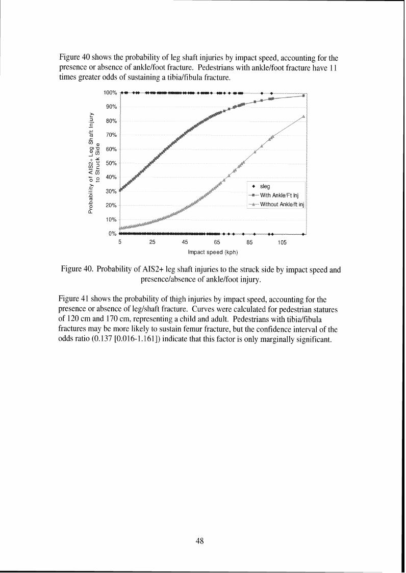
Figure 40 shows the probability of leg shaft injuries by impact speed, accounting for the presence or absence of anklelfoot fracture. Pedestrians with anklelfoot fracture have 11 times greater odds of sustaining a tibialfibula fracture.
Impact speed (kph)
Figure 40. Probability of AIS2+ leg shaft injuries to the struck side by impact speed and presencelabsence of anklelfoot injury.
Figure 41 shows the probability of thigh injuries by impact speed, accounting for the presence or absence of leglshaft fracture. Curves were calculated for pedestrian statures of 120 cm and 170 cm, representing a child and adult. Pedestrians with tibialfibula fractures may be more likely to sustain femur fracture, but the confidence interval of the odds ratio (0.137 [0.016- 1.16 11) indicate that this factor is only marginally significant.

p 80% 3 .- K + 120cm - With
70% OI
a F n 60% + a
Y 3 50% a ? ; 5 2 2 40% .- - .- I) m 30% I) e a 20%
10%
0% 5 25 45 65 85 105
Impact speed (kph)
Figure 41. Probability of AIS2t thigh shaft injuries to the struck side by impact speed, pedestrian stature, and presence or absence of leg shaft injury.
Figure 42 through Figure 44 show the risk of pelvislhip injury to pedestrians in the PCDS database. Impact speed, gender, age, and the presence or absence of thigh fracture are predictive of pelvislhip injury. Figure 42 shows the risk of pelvislhip injury for men. Pedestrians with thigh injuries are 11.5 times more likely to sustain pelvislhip injury than those without. Risk of pelvislhip injury increases with both age and impact speed. For male pedestrians without thigh fracture, 50% risk of pelvislhip injuries occurs at impact speeds of 97,80, and 63 krnlh, for 10-year-olds, 40-year-olds, and 70-year-olds, respectively. For male pedestrians with thigh fracture, 50% risk of pelvislhip injuries occurs at impact speeds of 60,44, and 27 km/h, for 10-year-olds, 40-year-olds, and 70- year-olds, respectively. Figure 43 shows the risk of pelvislhip injury for women. For female pedestrians without thigh fracture, 50% risk of pelvislhip injuries occurs at impact speeds of 8 1.65, and 48 kmth, for 10-year-olds, 40-year-olds, and 70-year-olds, respectively. For female pedestrians with thigh fracture, 50% risk of pelvislhip injuries occurs at impact speeds of 44,27, and 11 kmlh, for 10-year-olds, 40-year-olds, and 70- year-olds, respectively. Figure 44 shows results for 40-year-old pedestrians and indicates that women have 2.8 times greater odds of sustaining pelvislhip injuries in a pedestrian crash than men.

5 25 45 65 85 105
Impact speed (kph)
Figure 42. Probability of AIS2t pelvislhip injuries to the struck side for males by impact speed, pedestrian age, and presence or absence of thigh injury.
5 25 45 65 85 105
Impact speed (kph)
Figure 43. Probability of AIS2t pelvislhip injuries to the struck side for females by impact speed, pedestrian age, and presence or absence of thigh injury.

-20%
Impact speed (kph)
Figure 44. Probability of AIS2t pelvislhip injuries to the struck side for 40-year-olds by impact speed, pedestrian gender, and presence or absence of thigh injury.
Additional regression analysis was performed using vehicle factors as potential predictors of different types of lower extremity injury. Vehicle factors added to the pedestrian factors as potential predictors of injury were lower bumper height, top bumper height, ground-to-hood distance, ground to frontltop transition distance, front bumper lead and the ratio between pedestrian stature and height. Because these variables were not available for all cases, the number of lower extremity injuries included in the analysis was reduced from 418 to 342. When the regression analysis was performed using a larger number of potential predictors, the results differed from those in Table I I in only two cases, shown in Table 12 as models VIII and IX. For leg shaft injuries, top bumper height was selected as a predictor together with impact speed and the presence of an ankle injury. For pelvislhip injury, the bottom bumper height was selected as an additional predictor to those pedestrian factors previously selected. These analyses indicate that pedestrian factors seem to be stronger predictors of lower extremity injury than vehicle factors. To investigate whether vehicle factors are more predictive when pedestrian factors (such as age, gender, stature, and presence of other injuries) are not included as potential predictors, the logistic regression analysis was performed with only the vehicle variables (described above) and impact speed as potential predictors. For lower extremity, leg shaft, and thigh injuries, impact speed was selected as the only predictor. For knee fracture and knee strain injuries, no predictors were selected. As shown in Models X and XI in Table 12, impact speed and bottom bumper height were selected as predictors of AIS2t ankle injury, while impact speed and ground-to-front-top- transition distance were selected as predictors of AIS2+ pelvislhip injury.

Table 12. Factors contributing to the probability of AIS2+ lower extremity injury in PCDS pedestrian crashes when vehicle factors are considered potential predictors
Model
VIII
IX
X
XI
Dependent Variable
AIS2+ leg shaft injury
AIS2+ pelvislhip injury
AIS2+ ankle injury
AIS2+ Pelvislhip injury
n
342
342
460
460
Independent Variable
Impact Speed
AIS2+ ankle injury
Top bumper height
Impact speed
Age Gender AIS2+ thigh injury Ground-to-front- of-hood distance Impact speed Bottom bumper height Impact speed Ground-to- fronthop-transition distance
intercept alpha
5.186
-10-184
-2.5 15
-6.7
coefficient beta
0.053
2.184
-0.167
0.069 0.035 0.977 1.875 0.067
0.023 -0.022
0.066 0.027
standard error in beta 0.008
0.572
0.041
0.01 1 0.009 0.445 0.839 0.03 1
0.007 0.010
0.009 0.008
-210g (LR)
218.734
163.651
249.091
222.946
p- value
<0.001
<0.001
0.001
<0.001
R2
0.388
0.457
0.065
0.392
Wald chi- square p- value <0.001
<0.001
<0.001
<0.001 <0.001 0.028 0.025 0.032
0.001 0.023
<0.001 0.001
Odds ratios [95% CI]
1.054 [I .035: 1.0661
8.883 [ 2.897:27.234]
0.846 [0.781:0.916]
1.07 1 [1.049: 1.0941 1.036 [1.017: 1.0551 2.657 [I. 1 10:6.359] 6.520 [ 1.259: 33.7691 1.069 [I .006: 1.1361
1.024 [ 1.009: 1.0381 0.978 [ 0.960:0.997]
1.068 [ 1.05 1 : 1.0861 1.027 [ 1.01 1:1.044]

3. Biomechanical data
Kajzer et al. (1999, 1997, 1993, 1990) have performed several series of cadaver tests to study the response of the knee in lateral bending and shearing. Figure 45 through Figure 48 illustrate the test setups used in the different test programs. The key elements of each test series are summarized in Table 13. In the two later test series, the cadavers were of better quality (younger, not hospitalized prior to death) than those used in the first two series. The later tests were performed with the PMHS positioned horizontally rather than vertically. In the later tests, the impact mass was 6.25 kg rather than 40 kg. The later two test series used a single impactor face to provide shear load, while the original shear test procedure used a double impactor face to strike just below the knee and at the ankle. In all bending tests, impact was delivered to the ankle. All setups used a 400 N preload through the pelvis and fixed the femur at the trochanter and above the tibia1 plateau. Ground friction was minimized in all tests. In the latter two test series, loads were measured at the trochanter and above knee, and high speed video measured targets on femur and tibia. Damage was evaluated by looking at drop in shear force and bending moment and motion of targets.
Table Prochanter fixation screw
Knee fixation plate
Sirnufated qround
Figure 45. Kajzer et al. test setup for lateral dynamic shear tests at 40 and 20 lun/h (1999, 1997).

Trochanter fixation screw - Table
Styrodure @ Velocity sensor 1 Lo9d csl/
Mobile plate Impactor Accelerometer Spring
('Simulated ground) (rn=6.25kgf
Figure 46. Kajzer et al. test setup for lateral dynamic bending tests at 40 and 20 krnlh (1999, 1997).
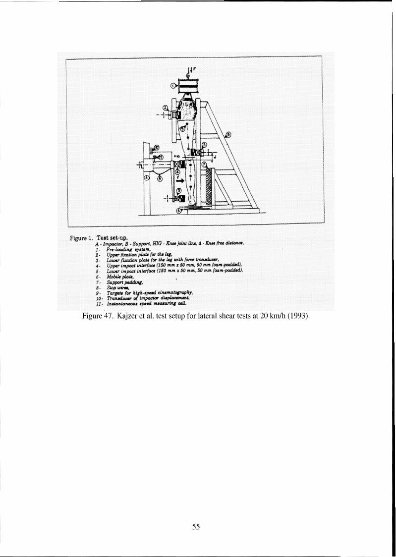
Figure 47. Kajzer et al. test setup for lateral shear tests at 20 k d h (1993).

F~,aure 2. Exga~me~~ea l test, sac-mp for d>xnlwis. loadirsg, -4 - Impactor; B - Suppofi; mG - &ee joixxt h a ; d - Knee free drstxnca; i + Pre-foadmg system: 2 - Upper fixatean plate for the thigh with hrce transducer: 3 - Lower fixation plate for the thigh with farce transducer; 4 - Impactor; 5 - Impactor hiace w~th hrse trmsducer and aceeierameur; 6 - hgobllft plate: T - S G O ~ wras: 8 - Line8 for high-speed clnemtlata@ap%my; 9 - Tr,asducer of' impactor dlsplacement: 113 - Iasaantslnaeaus speed measufing ceil,
Figure 48. Kajzer et al. test setup for lateral bending tests at 20 km/h (1990).

Table 13. Key features of Kajzer et al. knee impact tests I Publication vear 1 1990 1 1993 1 1997 1 1999
Test
Impactor mass 1 40 kg 1 40 kg 1 6.25 kg 1 6.25 kg
Impact Velocity Number of tests
Shear
Injuries: shear
15 and 20 km/h 19
Impactor face Cadavers
bending
15 and 20 k d h 17
double I Single Preserved, hospitalized prior to
Bending shear
single I Single Fresh, not previously hospitalized,
death, amputated at pelvis 78 years (SD7) 165 cm (SD 10) 66 kg (SD 12)
Injuries: bending
initial injury:
Bending Shear
40 k d h 10 each
whole body
Ligament:89% Knee fx: 95%
Tolerance at
initial injury: bendinn tests
20 k d h 5 each
5 1 years (SD 15) 170 cm (SD 12) 76kg(SD24) Ligament: 60% Knee fx: 50% Femur fx: 70%
-
-
In their first test series using lower velocity impacts in shear, Kajzer et al. (1990) identified two different injury mechanisms. The first occurred 5 ms after impact, and corresponds to the force generated by local acceleration (knee impact force), and results in injuries at the contact point and extra-articular injuries (fractures to fibula head and lateral tibia condyle, diaphysis fractures). The second mechanism (15-20 ms) correlated with force through the knee joint when the thigh is accelerated (knee reaction force), leading to intra-articular injuries of the knee joint (ligament injury, tibia intercondylar fractures, cartilage). Forces may rise after injury occurs because of a change in loading patterns through the leg, so the force level at the time of injury was used as a tolerance rather than peak force.
63 years (SD 15) 172 cm (SD 9) 82kg(SD13) Ligament: 60% Femur fx: 20%
1.8 (.4) kN
In the second test series, Kajzer et al. (1993) examined knee loading in lateral bending at lower velocities. The most common knee joint injury was MCL damage, which occurred at 10" of bending (measured using lines marked on the flesh). Moments at initial damage correspond to 101 Nm for 16 km/h and 123 Nm for 20 krnlh, with the differences attributed to viscoelastic effects. The knee bending moment was not clearly related to knee bending angle. Rotation of the whole leg about the longitudinal axis occurred in most tests, and is essential for developing tensile forces in knee ligaments. Rotation occurred because of the non-symmetry of the leg.
Tibia condyle fx: 12%
Ligament: 30% Ligament : 40% Knee fx: 10% 1 Knee fn: 20%
Ligament: 76% -
Femur fx: 70% 2.6 (.5) kN 2.4 (.2) kN

At the 40 km/h velocity (Kajzer et al. 1997) initial tissue damage was typically an articular fracture in lateral shear tests and femur supracondylar fracture or diaphysis fracture in bending tests rather than knee ligament damage. If ligament damage occurred, it occurred after the fracture. In laterarl shearing tests, initial damage to the knee joint occurred at an average knee joint force of 2.6 (.5) kN and an average bending moment of 489 (141) Nm. In bending tests, initial damage occurred at an average knee joint shear force was 1.5 (.6) kN and an average bending moment of 33 l(79) Nm. Damage to knee joint occurred at 5 ms in shear tests and 15 ms in bending tests. Initial displacement at initial injury was 16 to 28 mm. Loading speed of ligaments in the different setups could cause the differences in shear force and bending moment. The pattern of damage and tolerance levels differ in this study than from studies performed at lower velocities. Lower velocities tended to cause ligament damage, but ligament damage was less frequent at 40 kmlh tests. A limitation of this study is that most of the fractures occurred where the femur was supported just above the knee and may be a result of the boundary conditions used.
Results of the 1990 and 1993 studies differ from those of the 1997 Kajzer et al, study. Differences between the early and later programs included cadaver condition, test fixture setup, and velocity. To identify which of these factors likely led to these differences, Kajzer et al. (1999) performed an additional study using the test fixtures of the later study and cadavers with a better condition, but at the 20 k d h impact speed. Comparing early and later 20 kmlh tests, shear force levels were similar in shear tests, but the bending moment was substantially higher in the current bending tests. The similarity in shear force was likely due to differences in test setup, while the difference in bending moment were likely due to the quality of the PMHS. In the low velocity tests, ligament damage (ACL shear, MCL bending) occurred. In the high velocity tests, injuries were ACL damage and diaphysislarticular fractures for shear, and MCL damage and diaphysis fractures in bending. Occurrence of bone fracture related to impact velocity. Again, many of the fractures occurred near the support above the knee, limiting the application of the results of the study.
Kerrigan et al. (2003) discuss a different approach for understanding the failure tolerance of the pedestrian lower extremity to lateral impact. They tested eight tibias, eight femurs, and three knee joints in lateral three-point bending and two knee joints in lateral shear, with average velocity of 1.2 mls. Knee joints failed at the soft tissue or by epiphysis fractures. The mean lateral bending failure moment at the knee of 134 Nm SD 7 is much lower than the knee failure moment reported in the literature (284-351 Nm) or that of the tibia (291 Nm SD 69) or femur (382 Nm SD 103). Results suggest that boundary conditions are critical when studying lateral knee impact. Pedestrian-related leg testing should include the tibia, fibula, and flesh. The current study does not include axial load, which was present in the tests of Kajzer et al. (1997, 1999), which had higher failure bending moments.
Ramet et al. (1995) performed quasi-static tests on 20 PMHS legs. Six tests were to the whole body and fourteen were dissected at the hip. Two targets were mounted to the tibia and two to the femur. Tests were performed on a horizontal surface, the femur was

fixed, and a bar attached to the tibia to apply bending centered 1.5 m below the knee joint. For shear tests, the foot and femur were fixed on the surface and the knee impacted. They found no gender differences. Using the tests with good data, they found the moment to be 6.2 times the angle. The mean values of 19" and 129 Nm at first injury were higher than previous dynamic thresholds. In shear, they generated a force/displacement corridor; injuries in shear occurred between 12 and 22 mm and -75 to 3 kN. All quasi-static shear injuries were to soft tissue.
Bunketorp et al. (1983) performed 20 PMHS tests using standard and compliant bumper systems at two bumper heights (45 cm, 32.5 cm) at velocities of 30 km/h. While these tests may not be as relevant because they involved vehicle designs of 20 years ago, they are one of the few test conditions in which the acceleration of the PMHS tibia was measured. In the tests, unembalmed leg specimens including the hip joint were used, and a simulated body mass of 47 kg was placed on the leg, which was standing on a high- friction foot plate wearing a shoe. Accelerometers were at the ankle, impact level, and knee. The compliant, lower, bumper condition produced fewer serious injuries than the rigid high bumper; other comparisons were not statistically significant. In these tests, a lower or more compliant bumper reduced bumper force. No comminuted fractures or femur diaphysis fractures occurred at 30 km/h.
Cesari et al. (1988) performed 20 tests involving PMHS subjected to loading by vehicle bumpers. Cesari et al. (1989) performed additional analysis on some of the same tests. While these results are not as relevant because of the vehicle bumper designs involved in the impacts, they offer some insight into pedestrian lower extremity injury mechanisms. Each PMHS was in a walking position with both feet on the ground. Tests were performed at impact speeds from 20 to 39 km/h, and at five bumper heights set to between 60% and 12% of knee heights. Knee angles peak when impact occurs at the knee. Knee angles were similar for all impact speeds at the lowest three bumper heights, but were lower in the 20 km/h tests at the two higher bumper heights. At 20 k d h , long bone fractures occurred 20%, and knee joint injuries occurred 60% (at higher bumper heights). At 32 km/h, both types of injuries occurred 60% of the tests. At 39 k d h , long bone fractures occurred in 100% of the tests and knee injuries occurred in 25% of the tests. Bumper force did not vary with bumper height, but generally increased with impact speed, and therefore does not appear to be a predictor of injury. Equivalent mass of the legs was estimated. When the PMHS was impacted from the right, most injuries occurred to the right leg, and only the highest speeds produced fractures to the left leg. The left leg was no longer weight-bearing after the bumper impacted the right leg and the whole subject rotated before the medial aspect of the left leg contacted the bumper. Higher impact speed increased tibia acceleration. Ligamentous injuries without fracture occurred at knee angles above 30°, while instances without any knee injury occurred at knee angles below 15".
Kress et al. (1995) studied the failure of tibias and femurs in 558 tests. They used two test setups. The first was a linear impact into the bone with a 10 cm long, 4.13 cm diameter pipe at 7.5 m/s, driven by a 50 kg car. The second setup involved a pendulum impact using the same size of pipe at 1.2 or 5 m/s. They found ten different fracture

patterns during testing, and found that when the flesh was left on the bone, comminuted fractures were more likely to occur. They found more comminuted fractures in their embalmed specimens than in fresh or frozen. There were similar fracture patterns in the tibia and femur.
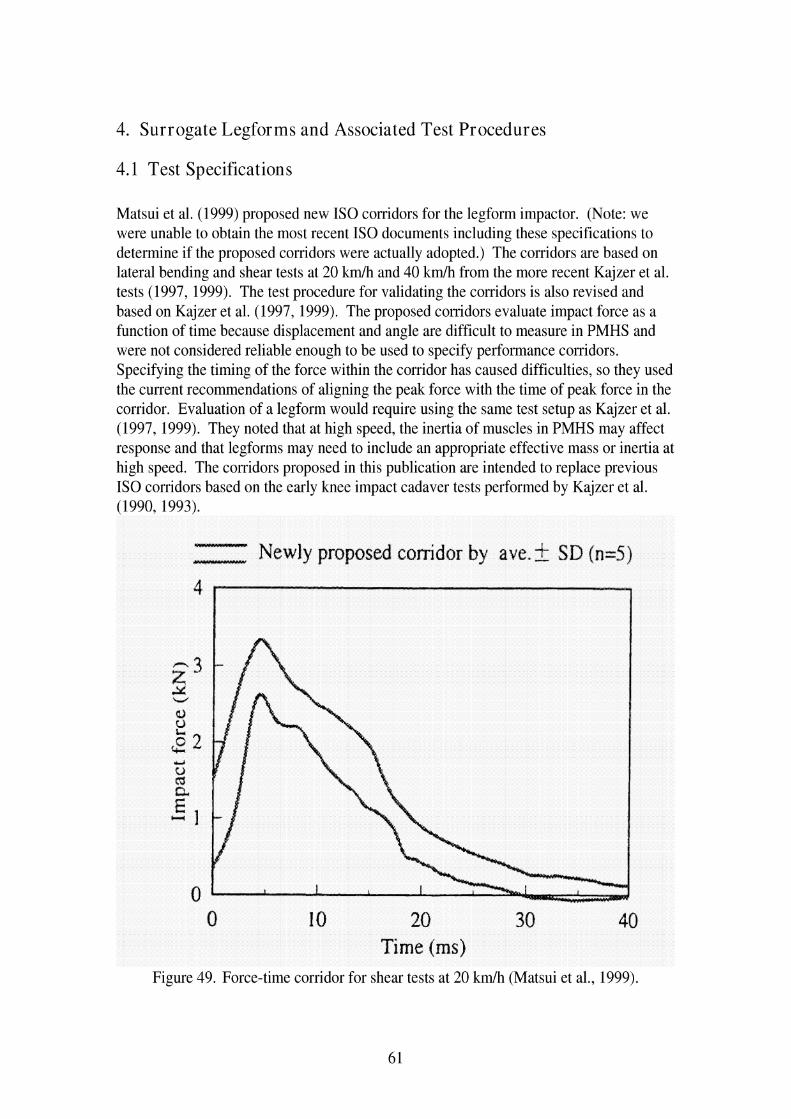
4. Surrogate Legforms and Associated Test Procedures
4.1 Test Specifications
Matsui et al. (1999) proposed new IS0 corridors for the legform impactor. (Note: we were unable to obtain the most recent IS0 documents including these specifications to determine if the proposed corridors were actually adopted.) The corridors are based on lateral bending and shear tests at 20 k d h and 40 k d h from the more recent Kajzer et al. tests (1997, 1999). The test procedure for validating the corridors is also revised and based on Kajzer et al. (1997, 1999). The proposed corridors evaluate impact force as a function of time because displacement and angle are difficult to measure in PMHS and were not considered reliable enough to be used to specify performance corridors. Specifying the timing of the force within the corridor has caused difficulties, so they used the current recommendations of aligning the peak force with the time of peak force in the corridor. Evaluation of a legform would require using the same test setup as Kajzer et al. (1997, 1999). They noted that at high speed, the inertia of muscles in PMHS may affect response and that legforms may need to include an appropriate effective mass or inertia at high speed. The corridors proposed in this publication are intended to replace previous IS0 corridors based on the early knee impact cadaver tests performed by Kajzer et al. (1990, 1993).
WlWlYMlll
ull*rruuwuu Newly proposed conidor by aye. 2 SD (n=5)
0 10 20 30 40 Time (ms)
Figure 49. Force-time corridor for shear tests at 20 km/h (Matsui et al., 1999).
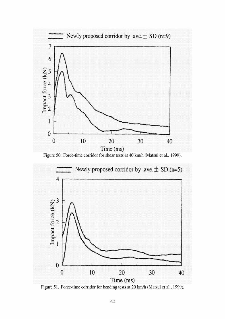
- - Newly proposed conidor by ave. k SD (n=9)
0 10 20 30 40 Time (ms)
Figure 50. Force-time corridor for shear tests at 40 kmlh (Matsui et al., 1999).
- Y Newly proposed corridor by ave. k SD (n=5) 4
0 10 20 30 40 Time (ms)
Figure 51. Force-time corridor for bending tests at 20 kmlh (Matsui et al., 1999).
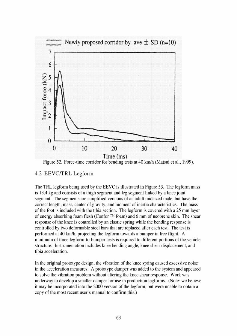
- L19*Um)lldYI Newly proposed corridor by ave.? SD (n=IO)
0 10 20 30 40 Time (ms)
Figure 52. Force-time corridor for bending tests at 40 km/h (Matsui et al., 1999).
4.2 EEVCITRL Legform
The TRL legform being used by the EEVC is illustrated in Figure 53. The legform mass is 13.4 kg and consists of a thigh segment and leg segment linked by a knee joint segment. The segments are simplified versions of an adult midsized male, but have the correct length, mass, center of gravity, and moment of inertia characteristics. The mass of the foot is included with the tibia section. The legform is covered with a 25 mm layer of energy absorbing foam flesh (Confor TM foam) and 6 mm of neoprene skin. The shear response of the knee is controlled by an elastic spring while the bending response is controlled by two deformable steel bars that are replaced after each test. The test is performed at 40 kmlh, projecting the legform towards a bumper in free flight. A minimum of three legform-to-bumper tests is required to different portions of the vehicle structure. Instrumentation includes knee bending angle, knee shear displacement, and tibia acceleration.
In the original prototype design, the vibration of the knee spring caused excessive noise in the acceleration measures. A prototype damper was added to the system and appeared to solve the vibration problem without altering the knee shear response. Work was underway to develop a smaller damper for use in production legforms. (Note: we believe it may be incorporated into the 2000 version of the legform, but were unable to obtain a copy of the most recent user's manual to confirm this.)

Thigh segment
Leg segment
Figure 53. Diagram of EVC legform (Takahashi and Kikuchi, 2001).
Injury criteria proposed by the EEVClWG17 (1998) are a shear displacement of 6 mm, maximum shear force of 4 kN, and maximum bending angle of 15". These criteria are aimed toward preventing serious ligament damage and tibia fractures. The shear displacement was selected to represent a 4kN shear force. JARIIJAMA representatives have proposed a combined maximum bending angle and maximum shear displacement criteria, but the WG 17 was not in favor of this approach because the maxima occur at different times.
The basis for the injury criteria are the quasi-static tests by Ramet et al. (1995), who concluded, based on review of other literature, that injury occurs dynamically at a lower angle than when it occurs statically, but the failure moment of -134 Nm is the same for quasi-static and dynamic tests.
Kajzer et al. performed tests with the TRL legform using the setup of the Kajzer et al. (1997) tests to produce a transfer function between the cadaver and impactor responses. Results suggest that the criteria of 6 mm shear displacement, 4 kN shear force, and 15" bending angle are appropriate. However, Kajzer et al. (1997) note that the TRL legform

is based on low velocity test data (15-20 kmth) but run at 40 krnlh. They note, "The results of the current [I9971 study indicate that the injury mechanism and tolerance from low velocity experiments cannot be transformed to high velocity situations".
Originally, the TRL legform was calibrated using a test procedure similar to that used for checking ATD necks. However, a revised procedure has been developed that more closely resembles the type of impact loading seen in the test procedure. The legform is suspended horizontally by cables and struck at the knee with a linear impactor. The TRLIEEVC legform has been shown to be repeatable under test impact conditions with a simulated repeatable car and in dynamic certification tests, with coefficients of variation for knee angle, knee displacement, maximum acceleration, and impact velocity of less than 5% in each condition (Lawrence and Hardy 1998).
The properties of the deformable ligaments are specified by static and dynamic bending response corridors. Recommended practice specifies that for each batch of 22 ligament pairs manufactured from a piece of steel stock, one pair of ligaments is checked statically and another checked dynamically. In addition, TRL (the ligament manufacturer) tests one pair of ligaments statically from each batch of 50.
Questions have arisen as to how the width of the ligament bending response corridor might affect the response of the legform. Lawrence and Hardy (1998) estimate using ligaments at either extreme of the bending corridor could shift the bending angle response by +I-14%. Additional testing to investigate the width of the ligament response corridor on legform response is underway.
The mechanical limits of the shear spring allow a maximum shear displacement only 15% over the tolerance criteria of 6 mm. Lawrence and Hardy (1998) suggest that this is sufficient for a regulatory device, even if greater overload capacity might be desired for research purposes. They point out that the bending and acceleration have a much larger overload capacity, and that bumper systems that meet the bending and acceleration requirements typically meet the shear requirements.
Green (1998) reports on tests with the EEVC legform on eight different vehicles to examine the repeatability and reproducibility of the legform test procedure. None of the vehicles met all of the legform tolerance criteria. The response data were masked by an 80 Hz vibration, which led addition of damper described previously. Many of the tests likely reached the physical bending angle and shear displacement limitations of the test device. Tibia acceleration exceeded 150 g in 17 of 21 cases. The device did not exhibit high repeatability or reproducibility (comparing results for two labs) even for a vehicle that did not reach the limits of the test device. The problem of the device reaching its mechanical limits could censor the acceleration measurements as well.
In recent EuroNCAP tests, 34 vehicles have been tested with the TRL legform using the EEVC procedure in 101 tests. Of these tests, 7.9% passed the current criteria and 16% were within 25% of the test requirements.

The use of the neoprene skin and Confor TM foam as part of the TRL legform structure has been criticized as not being sufficiently biofidelic or well-specified. Lawrence and Hardy suggest that the response is sufficiently controlled by the dynamic certification test. As with most ATDs, the legform does not have a humanlike distribution of mass because of its construction using steel bones and foam flesh. They suggest that the energy absorption characteristics of the legform flesh will have little effect on response compared to the energy absorption characteristics of the vehicle.
4.3 POLAR Dummy Legform
Several papers have described development of different versions of the POLAR legform. Figure 33 illustrates the features of this legform.
Figure 54. Diagram of POLAR dummy legform (Takahashi and Kikuchi, 2001)..
Artis et al. (2000) describe preliminary efforts to develop the POLAR legform. They note that the early TRL and JAR1 legforms were not scaled to a midsized male size, and are based on cadaver tests performed on elderly cadavers that had been hospitalized before death and preserved afterwards. The paper discusses the process used to design ligaments. Modeling results showed that pedestrian kinematics did not show a great difference when either a deformable or breakable tibia was used, so the legform includes a deformable tibia. The bending response is slightly higher than desired. The shear response matches the newly proposed I S 0 corridor fairly well at 20 krnth, but has a second peak at 40 k d h outside the corridor because it does not simulate fracture.

Akiyama, Okamoto, and Rangarajan (2001) describe the development of the POLAR pedestrian dummy. Wittek et al. (2001) describe how the lower extremity of the POLAR pedestrian dummy is also being developed as a separate legform testing device. Akihama et al. (1999) report on the initial developments of the POLAR dummy. The upper body design is based on THOR, while it has more detailed knee structure, including reusable spring/tube/cables for each of the main ligaments, femoral condyles, and meniscus. The PMHS bending and shearing tests performed by Kajzer (1997, 1999) were performed on the POLAR leg. Results showed that the peak force in bending was about 15% higher, but the response shapes were similar. Five-axis load cells are placed above and below the knee, and accelerometers are placed on the femur, tibia, and above and below the knee. The leg used urethane tibias. The tibia does not have the ability to simulate fracture, but they performed computer simulations showing that tibia fracture would have only a limited effect on final body trajectory. Full-scale reconstruction tests showed that the head kinematics were reasonable, although the correlations between bending moments, accelerations, and angles with injury level is not clear and needs additional study.
4.4 Other legforms
There have been several other legforms developed to study pedestrian lower extremity injury. While this list is not exhaustive nor detailed, reports on some of these legforms provide insight on different issues involved in developing a pedestrian legform.
Konoso and Tanahashi (2003) developed a new 2002 version of the JAMA-JAR1 legform impactor. The size and shape are similar to the TRL legform. The knee joint incorporates a ligamentous system similar to that of the POLAR pedestrian dummy. The femur and tibia are each built of nine to eleven connected cylindrical sections that simulate the flexibility of the bone. The tibia, femur, and knee joint segments have good biofidelity compared to the response of cadaver component tests. The legform as a whole also compares favorably to IS0 specifications based on the 1997 and 1999 Kajzer et al. tests. They believe using a legform with flexible bones provides more realistic response and measurement of accelerations.
Marous et al. (1998) developed a non-frangible pedestrian legform impactor. Its design is based on the original I S 0 specifications (based on the 1990 and 1993 Kajzer et al. tests). The legform has cylindrical segments to represent the tibia and femur. Bending response of the knee is controlled by a clutch-type mechanism, while the shearing response of the knee is controlled by viscoelastic elements that permit the tibia segment to shift relative to the femur segment. Bending angle and shear displacement are measured separately. The legform was considered a prototype and additional refinements and validation would be required for its further use.
Sakurai et al. (1994) evaluated measurements using different legform designs. They performed tests with the 1993 version of the JAR1 impactor, which is cylindrical and uniform in diameter over the whole length, and measures shear force, bending moment, tensile force, and knee angle above and below the knee. This design is similar to an INRETS impactor design (the predecessor to the TRL legform), but has greater

measurement capability. They also ran tests with the 1992 version of the JAR1 impactor, which has a symmetric cone-shaped thigh. Tests were performed with both impactors with and without a Hybrid 11-Pedestrian upper body attached through a hip joint. Rather than projecting the legforms into the bumper, the legforms were impacted by a vehicle mounted on a sled. Bumper height and lead were varied. Measurement trends were similar with and without body mass for both impactors. Measures that varied with the presence of an upper body mass under some conditions were axial force, hood-edge force, and knee angle.
Cesari, Alonza, and Matyjewski (1993) describe development of an instrumented mechanical leg for bumper subsystem testing. The legform includes two deformable bars to reproduce a biofidelic forcelangle history. In launching the leg, it is propelled by a small sled that stops before impact while the legform continues in free motion. Two deformation transducers measure bending angle and shearing. Proposed tolerances are an angle of 15", 5mrn13kN shear displacementlforce, and upper tibia acceleration of 150 g. They also performed simulations with a MADYMO pedestrian dummy, adjusting the lower limb characteristics to match the torquelangle characteristic of the legform. They varied bumper height, and performed simulations using the whole dummy, just one limb, or one limb with additional mass. The whole dummy model was considered the baseline. The model of the limb with additional mass on top matched results of the whole dummy better than the model of the limb alone.
Cesari, Cavallero, and Roche (1989) evaluated the Round Symmetrical Pedestrian Dummy (RSPD) leg. The legform consisted of foot, leg, and thigh components, with a single deformable rod at the knee, a cone-shaped thigh, and an adjustable ball and socket joint at the hip. The mass of the RSPD was 1.5 times that of a single human leg to account for the partial mass of the nonstruck leg. The RSPD was instrumented with ten sets of strain gauges over its length and accelerometers at two locations on the tibia. Its response was compared to that of cadavers impacted by a vehicle bumper at 32 km/h. Film analysis was used to calculate bending angle. Bumper peak force was higher with the RSPD than cadavers by 50%, indicating that the selected RSPD mass is inappropriate.
4.5 Evaluation of legform test methods
Anderson et al. (2002) performed reconstructions of ten pedestrian crashes using numerical and laboratory methods. The goal was to compare the injuries resulting from head and leg impacts incurred in pedestrian collisions with the results from the corresponding subsystem test. The reconstructed crashes were selected from among 80 pedestrian crashes collected by the Australian Commonwealth Department of Transport and Regional Services. The distribution of injuries by body region and AIS for this set of crashes is shown. A MADYMO pedestrian model was used to simulate the crashes, with the average male model scaled to match the pedestrian's size. The vehicle geometry was approximated with planes and ellipsoids. Physical reconstructions of each test were performed using the EEVC headform, upper legform, and legform. For the legform impact reconstructions, severity of injury below the knee appears to be positively associated with higher tibia accelerations, but the EEVC limit of 150 g appears low.

They discuss that perhaps the criteria is set correctly, but the design of the legform produces accelerations that are too high. Knee bending angle and knee shear displacement appeared to have little correlation with knee injury, possibly because the test idealizes knee loading to be completely lateral, which rarely occurs in real collisions. They discuss that the rigid tibia of the legform amplifies the bending and shearing of the knee.
In their paper proposing new IS0 corridors for the legform impactor, Matsui et al. (1999) tested the TRL and JARI legforms using the new proposed corridors. Results of their tests are shown in Figure 55 through Figure 58. Shear results for both legforms were too stiff. The TRL legform was not tested in shear at the higher velocity because of concerns that it might be damaged. The results were close in bending at 20 k d h , and slightly high in bending at 40 k d h . The lateral shearing displacement was lower than that seen in PMHS.
TRL legform impactor (n=2) JAR1 legfom impactor (n=2) Newly proposed corridor
-10 -5 0 5 10 15 Time (ms)
Figure 55. Response of TRL and JARI legforms compared to shear force corridor for 20 km/h (Matsui et a1.,1999).
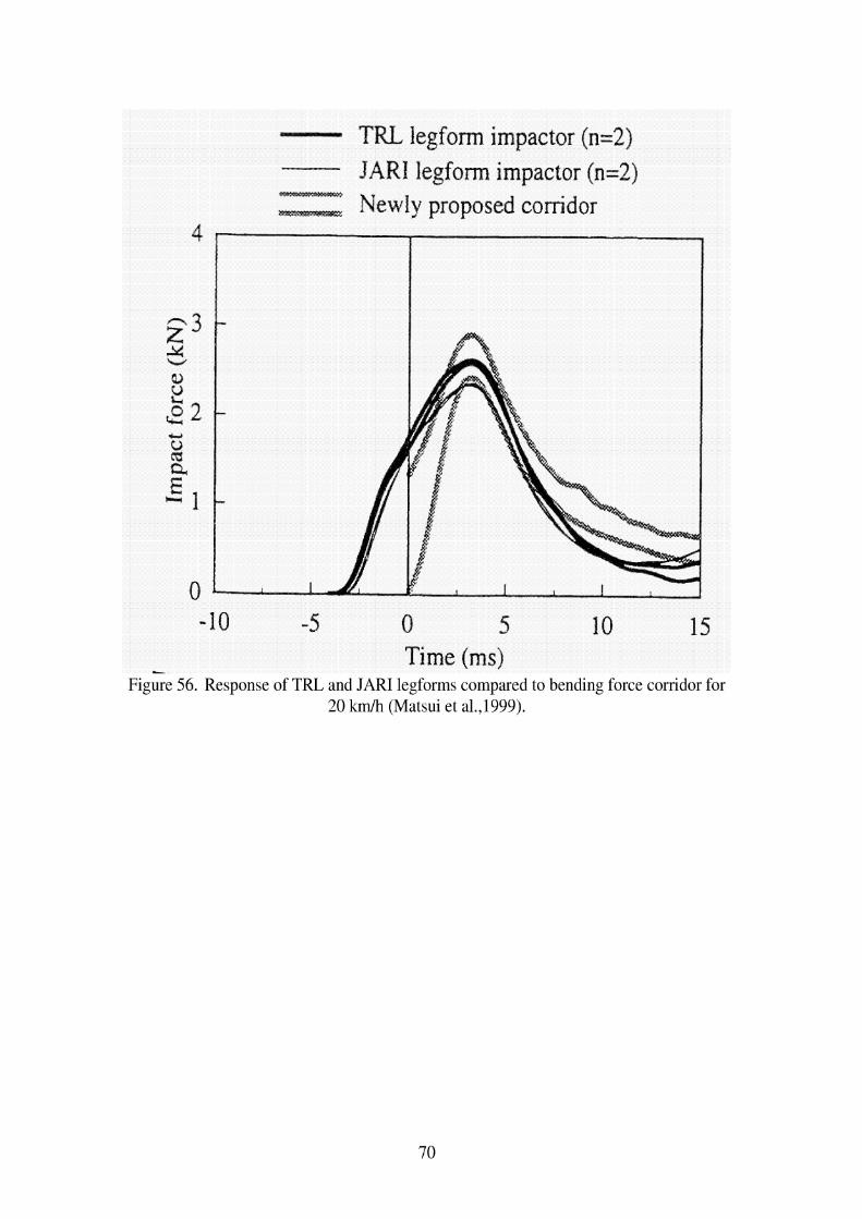
- TRL legform impactor (n=2)
JARI legform impactor (n=2) Newly proposed corridor
- 10 -5 0 5 10 15
- Time (ms) Figure 56. Response of TRL and JARI legforms compared to bending force corridor for
20 km/h (Matsui et a1.,1999).

JAR1 legform impactor (n=2) Newly proposed conidor
0 5 Time (ms)
Figure 57. Response of JAR1 legforms compared to shearing force corridor for 40 km/h (Matsui et al., 1999).

Lllllllllll TRL legform impactor (n=2)
JAR1 legform impactor (n=2) Newly proposed corridor
-10 -5 0 5 10 15 Time (ms)
~ i k e 58. ~ e s ~ o n s e of TRL and JAR1 legforms compared to bending force corridor for 40 k d h (Matsui et a1.,1999).
Takahashi and Kikuchi (2001) used finite element models (FEM) of the EEVC-type legforms, the POLAR pedestrian dummy, and a human lower limb to study the relationship between vehicle bumper height, knee shearing displacement, and bending angle of the knee. In their parameter study that varied bumper height, they found that the dynamic response of the POLAR FEM was similar to that of the human lower limb FEM. As shown in Figure 59 on the left, the shearing displacements of the human, POLAR, and legform models showed similar trends with bumper height although the absolute values are not always the same. The same figure on the right shows that the bending angle response of the human and POLAR dummy models are very close, but the TRL legform response does not increase with increasing bumper height as the other two do.

%a .+. SR 5 40 Q - Sn 8 30
e 2 20 a, m + Human madcl
10 + Dlimrnv model ~ e d o r k model
Figure 59. Comparison of shearing displacement (left) and bending angle (right) as a function of bumper height using FEM of a human lower extremity, the POLAR lower
extremity, and the rigid legform (Takahashi and Kikuchi, 2001).
Matsui (2001) analyzed the Kajzer et al. (1997, 1999) data statistically to estimate injury risk curves based on the data. He looked at both initial and subsequent injury. Both the low- and high- speed data were combined into one dataset. Values at the time of injury were used for all possible injury criteria except for impact force and tibia acceleration, which used maximum values. Acceleration was based on digitized points since it was not measured during the tests, and force was calculated as the impactor mass times the acceleration. Injury risk analysis was performed using the modified maximum likelihood method of logistic regression. Tests were performed with the TRL legform (version 2000), using the same test procedure as in the Kajzer et al, tests. In the PMHS tests, tibia acceleration and impact force were associated with likelihood of tibia fracture, while shear displacement was the only measure associated with ligamentous injury. The author presents comparisons of the updated TRL legform versus the newer corridors proposed by Matsui (1999), but found minimal differences between the 1995 and 2000 versions of the legform. The author developed a transfer function between the TRL legform and the PMHS shear displacement measures as shown in Figure 60 and impact force. Matusi states that since the TRL legform is not biofidelic, injury tolerance values based on cadavers cannot be directly applied to the legform, and these transfer functions are necessary.
Figure 60. Transfer function for shear displacement between PMHS and TRL 2000 legform
Probability of ligament injury Shearing displacement (mm) PMHS I TRL 2000 legform

Figure 61. Transfer function for impact force between PMHS and TRL 2000 legform
Matsui, Wittek, and Konosu (2002) performed tests with the POLAR dummy and the EEVC legform and upper legform on a compact passenger car and SUV. In the POLAR tests, the knee shearing displacement and bending angle were calculated by digitizing film, since this version of the dummy did not include sensors to measure angle or displacement. In comparing kinematics between the dummy lower extremity and the legform, the legform rebounded from the car bumper after 20 ms of contact, while the dummy lower extremity remained in contact with the bumper. For the SUV, the tibias of the legform and dummy tended to rotate under the bumper. In the first 20 ms of data, the knee shear displacement was similar in the legform and dummy for the compact car, but was higher in the dummy for the SUV. The bending angle of the dummy was higher than the legform for both vehicles, possibly because of the presence of the upper body mass. The legform acceleration was approximately double that of the dummy under all conditions, possibly because of the deformable leg of the POLAR dummy.
Probability of ligament injury
.2
.4
.5
Matsui (2003) performed crash reconstruction tests with the TRL legform to estimate injury reference values for use with the test procedure. Reconstructions were performed using fifteen crashes with impact speeds ranging from 35 to 45 k d h in which an adult pedestrian was struck. Seven cases involved fractures of the tibia and/or fibula, four involved ligamentous injury, and four sustained no injury. The same model vehicle involved in the crash was used in the study. Three cases reached the bending limit of the legform. Tibia acceleration was scaled from average American male to the size of the Japanese pedestrian involved in the crash. Tibia acceleration was shown to be predictive of tibia fracture (p<.05), while bending angle was marginally predictive of ligamentous injury (p=.061). When developing injury risk curves for the TRL legform, 26.5" corresponded to a 50% probability of ligamentous injury, while 203 g corresponded to a 50% probability of tibia fracture.
Bhalla et al. (2003) performed additional analysis on the cadaver tests performed by Kerrigan et al. (2003). They reviewed the literature to identify specific injuries sustained by pedestrians in real crashes, and concluded that the tests of Kajzer et al., which included fractures outside the knee joint, should not be used to characterize the tolerance of the knee joint. Their method of testing the knee joint produced the types of injuries seen in real crashes. They concluded that pure shear loading of the knee joint rarely occurs in real crashes. They performed tests on the TRL and POLAR I1 knee joints using their test procedure, and found them both to be stiffer than the knees of PMHS in pure bending, although the POLAR I1 was closer to the cadaver response than the TRL legform. Both were stiffer than cadavers in pure shear.
I m ~ a c t force (kN) PMHS
3.7 4.6 5.0
TRL 2000 legform 5.1 6.4 6.9

Ishikawa et al. (2003) performed tests using the EEVC subsystem tests and the full POLAR dummy. Impacts were performed to a compact car equipped with different pedestrian protection countermeasures at 25 kph and 40 kph. The tibia accelerations for the dummy and impactor were close for all conditions. The displacement and bending angle of the knee were much larger for the full-size dummy tests because of the inertia of the dummy's upper body and from ground friction. These measures did not correlate well with the different countermeasures being tested. The moment and load measured at the knee of the full dummy appeared to be more closely correlated with the countermeasures.


5. Testing Issues
Konosu, Ishikawa, and Takahashi (2001) used a FEM of a human leg to estimate the effect of using a rigid versus flexible tibia in a legform impactor. When they ran their human model setting the tibia to be rigid, all of the energy is absorbed by the ligaments, which ruptured. When the flexible tibia is used, the whole leg experienced more deformation, and no ligament injury was predicted. As illustrated in Figure 62 and Figure 63, they found it inappropriate to estimate tibia fracture by using only the upper tibia acceleration, because the peak acceleration depends on the impact point, which varies with bumper height. Also, when a rigid legform was impacted away from the knee, it rotated rather than bent, so the acceleration increased with distance from the knee, and a small acceleration at the upper tibia would not be sufficient for judging the possibility of fracture lower on the tibia. They recommend using a flexible legform impactor to minimize these complications.
Figure 62. FEM simulation illustrating that peak acceleration occurs where the leg fracture occurs, suggesting that low acceleration measured at the top of the tibia does not
predict mid-shaft tibia fractures (Konosu, Ishikawa, and Takahashi, 2001).

T~me (ns)
Tendency of acceleration drfFer between human leg
lddle and rigid legform impactor
Figure 63. FEM simulations illustrating how a deformable legform has the highest tibia acceleration at the fracture site, while acceleration of a rigid legform is highest near the distal leg end and low near the proximal end (Konosu, Ishikawa, and Takahashi, 2001).
Takahashi and Kikuchi (2001) used finite element models (FEM) of the EEVC-type legform impactor, the POLAR pedestrian dummy, and a human lower limb to study the relationship between vehicle bumper height, knee shearing displacement, and bending angle of the knee. Their study rotated the left and right legs 10" in extension and flexion, respectively. As shown in Figure 64, Takahashi and Kikuchi (2001) explored the effect of bone rigidity in their human model. The contribution of a flexible bone rather than a rigid bone had no effect on shearing displacement, but had some influence on bending angle at higher bumper heights. They also explored the effect of adding an upper body mass, comparing responses of the whole human FEM, only the lower extremity, and the lower extremity with a concentrated mass on top. Results of this analysis shown in Figure 65 indicate that upper body mass significantly affects the bending angle of the knee but not the shear displacement. Figure 66 shows that the presence or absence of an ankle joint had no influence on either measure.

Figure 64. Effect of bone deflection on shearing displacement and bending angle (Takahashi and Kikuchi, 200 1).
- -tab- Full my -rc* Cmer ltmb whh addrto
bcnver limb only
+ Full bmy -II- Lower limb with additional mss
Lowr ltmb only P
Figure 65. Effect of upper body mass on shearing displacement and bending angle (Takahashi and Kikuchi, 200 1).
Figure 66. Effect of ankle joint on shearing displacement and bending angle (Takahashi and Kikuchi, 2001).
Using the human lower limb FEM, Takahashi and Kikuchi (2001) also analyzed tensile strains in four principal knee ligaments, and suggested that a combination of shearing displacement and bending angle should be considered when developing an injury criteria for knee ligaments. As shown in Figure 67, they present a plot of proposed bending angle versus shearing displacement criteria, using simulations of PMHS tests performed
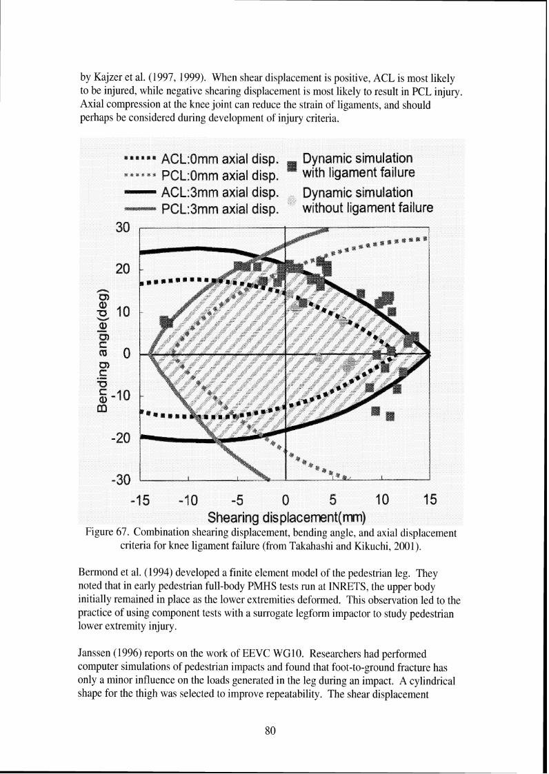
by Kajzer et al. (1997, 1999). When shear displacement is positive, ACL is most likely to be injured, while negative shearing displacement is most likely to result in PCL injury Axial compression at the knee joint can reduce the strain of ligaments, and should perhaps be considered during development of injury criteria.
e a lt l rP a ACL:Omm axial disp. Dynamic simulation s C 8 C a B PCL:Qmm axial disp. ' with ligament failure
ACL:Jmm axial disp. Dynamic simulation PCL:dmm axial disp. without ligament failure
30
-30 -15 -1 0 -5 0 5 I 0 15
Shearing dis placemnt(m) Figure 67. Combination shearing displacement, bending angle, and axial displacement
criteria for knee ligament failure (from Takahashi and Kikuchi, 2001).
Bermond et al. (1994) developed a finite element model of the pedestrian leg. They noted that in early pedestrian full-body PMHS tests run at INRETS, the upper body initially remained in place as the lower extremities deformed. This observation led to the practice of using component tests with a surrogate legform impactor to study pedestrian lower extremity injury.
Janssen (1996) reports on the work of EEVC WGlO. Researchers had performed computer simulations of pedestrian impacts and found that foot-to-ground fracture has only a minor influence on the loads generated in the leg during an impact. A cylindrical shape for the thigh was selected to improve repeatability. The shear displacement
requirement of 6 mm was based on a 25-30 mm length of ACL in cadavers and a 20% elongation at rupture.
In their modeling work to explore shortcomings of a rigid legform impactor, Konosu, Ishikawa, and Tanahashi (2001) developed injury risk curves for shearing displacement and bending angle based on the cadaver tests run by Kajzer et al. (1999, 1997). The injury risk curve showed a 50% risk at 24.2 mm or 19.8". They also developed injury risk curves based on Ramet quasi-static loading, with 50% risk at 22.7 mm or 21.8". They also note that in the EEVC test procedure, the relationship between upper tibia acceleration and fracture is based on PMHS tests by Bunketorp (1983). If tibia, fibula, or both fractures are used to estimate tolerance, acceleration level should be 198 g, but if tibia or tibiatfibula fractures are used to estimate tolerance, it is 240 G, which may be more appropriate as an initial target. Another problem is that the effect of a tibia that bends varies with the height of the impact, and only one bumper height was used in the Bunketorp tests.


6. Observations and Recommendations
This report on pedestrian lower extremity injury has identified several issues to consider when developing a legform and associated test procedures for evaluating vehicle front- end performance relative to reducing lower extremity injury in pedestrian crashes.
The analysis of overall headlface and lower extremity injury patterns in the PCDS database suggests that the number of AIS2t injuries sustained by a pedestrian, and the overall likelihood of a pedestrian to sustain injury to a particular body region, will not substantially change as LTVs make up greater proportions of the US vehicle fleet. However, because analysis of injuries by source indicates that both headlface and lower extremity injuries are more likely to result from a relevant source (i.e. one covered by proposed test procedures) on passenger cars than LTVs, proposed test procedures for pedestrian injury mitigation will be more effective for injuries caused by passenger cars than for LTVs. Pedestrian injury mitigation efforts for LTVs should first address pedestrianlvehicle interaction, so the pedestrian is more likely to be struck by a vehicle component that could be designed to reduce likelihood of injury.
The focus of most pedestrian legform test procedures has been on preventing ligamentous damage to the knee, largely because early tests loading the knees of PMHS showed high frequencies of ligamentous injury. However, analysis of the PCDS database indicates that fractures to the knee region are three times as frequent as soft-tissue injuries to the knee. In addition, results of recent cadaver tests by Kajzer et al. show that ligamentous injuries commonly occur at 20 k d h , but both fractures and ligamentous injuries are likely to occur at 40 k d h , which is the speed proposed for legform test procedures.
These findings raise questions about the focus on preventing knee soft-tissue injuries. If possible, the larger pedestrian injury database compiled by IHRA should be used to study the types of knee injuries sustained in later model vehicles. Goals of this analysis would be to identify the conditions under which knee soft-tissue injuries occur and to determine if the trends found in the PCDS database hold true with a larger dataset. Designing the legform to reduce fractures at the knee joint, which are also disabling, may be more justified than the focus on soft-tissue injury. In the PCDS database, the only predictor identified with knee soft-tissue injury is knee fracture. Designing vehicles to reduce knee fracture may also reduce the likelihood of knee ligamentous injury.
The analysis of the PCDS database showed that tibiatfibula shaft fractures are not only the most frequent type of pedestrian lower extremity injuries, but are associated with the likelihood of knee and thigh fracture. Because of this, the legform test procedure should address tibia fractures. The issues raised using modeling simulations with a deformable or rigid tibia and the location of tibia acceleration measurement should be addressed. Impacts should be performed, in the laboratory or simulated with models, to identify how acceleration varies along the tibia when impacted with current styles of bumpers, since much of the data used to establish tibia tolerance is based on cadaver testing performed in

1983. In addition, there may be better ways of measuring the likelihood of tibia fracture such as peak pressure or force at the contact area.
Another issue identified in the literature is the lack of specificity regarding the location of tibia injury. Fractures to the tibial plateau or tibial condyles, located within the knee joint, are typically more debilitating than those to the tibia shaft. It is unclear from the literature whether what the relative frequency of tibia shaft and tibia knee joint fractures is. Even most legform test procedures are vague as to whether the goal is to prevent tibia fractures to the shaft or at the knee, since acceleration is measured near the top of the leg shaft. Further analysis of pedestrian crash data should specifically separate tibia shaft and other fractures.
Results from the cadaver tests by Kajzer et al. (1997, 1999) have been used to develop IS0 corridors for legforms and are the basis for the most recent designs of pedestrian lower limbs. However, the test setup does not necessarily provide the best representation of pedestrian lower extremity loading by a vehicle bumper, since it is supported just above the knee. Many of the fractures reported in the tests occurred at this support, suggesting that the boundary conditions may not be appropriate for representing pedestrianlvehicle contact.
Several researchers have used finite element models of the lower extremity and entire pedestrian to study kinematics of pedestrians and examine potential injury criteria. However, Takahashi et al. (2000) have noted that mechanical properties of ligaments have not been determined at loading rates greater than 1 Hz. If computer models are to be useful as a design tool for developing pedestrian-friendly vehicles, the material properties of knee ligaments should be determined at speeds representative of those occurring during pedestrian impacts.
Documents (EEVClWG17 1998, Larence and Hardy 1998) discussing the EEVCITRL legform are dismissive of any new biomechanical data that suggest the legform and procedure may not be appropriate. Kajzer et al. (1997) note that the TRL impactor is based on low speed test data (15-20 krnlh) but is tested at 40 k d h . The results from work at higher speeds, which show different injury patterns and tolerance than at low speeds, suggest that low-speed injury and tolerance results cannot be extrapolated to high velocity situations. While the EEVC WG17 does not accept the more recent Kajzer et al. data as a better guide for designing the response of the legform, they selectively use some test results by Kajzer et al. performed on the EEVC legform to confirm the injury criteria already selected.
Researchers from Japan have performed some interesting modeling work to study the effects of deformable tibia and presence of upper body mass on legform response. They have also developed the POLAR legform, which incorporates a deformable tibia. While the model results suggest that this may be a much more realistic approximation of the lower extremity, particularly in terms of acceleration response, the POLAR legform is relatively new, and more experience with this test device is needed before it can be used in regulation. Performing reconstruction tests of real pedestrian impacts with the legform

would help determine appropriate injury reference values to use with the device. Thus, while the POLAR legform has features that may make it a better tool in predicting lower extremity pedestrian injuries, there is general agreement that it is several years from being a regulatory test device. Therefore, researchers have also been attempting to develop alternative injury tolerance values for use with the TRL legform that correlate better with reconstructions of recent pedestrian crashes. The two recent papers by Matsuj (2001, 2003) suggest alternative injury tolerance values that attempt to compensate for some of the nonbiofidelic characteristics of the TRL legform.


7 . References
Akiyama, A., Okamoto, M., and Rangarajan, N. (2001). Development and application of the new pedestrian dummy. Proceedings of the 17th International Technical Conference on the Enhanced Safety of Vehicles. Report No. 463. National Highway Traffic Safety Administration, Washington, D.C.
Akiyama, A., Yoshida, S., Matsuhashi, T., Rangarajan, N., Shams, T., Ishikawa, H., and Konosu, A. (1999). Development of simulation model and pedestrian dummy. Advances in Safety Technology 1999 (SAE-SP-1433). Warrendale, SAE, p. 43-5 1. Report No. SAE 1999-01-0082.
Anderson, R., McLean, J., Streeter, L., Ponte. G., Sommariva, M., Lindsay, T., and Wundersitz, L. (2002). Severity and type of pedestrian injuries related to vehicle impact locations and results of sub-system impact reconstruction. Proceedings of the 2002 International Conference on the Bionzechanics of Impacts. IRCOBI, Munich, Germany.
Artis, M., McDonald, J., White, R., Huang, T. J., Shams, T., Rangarajan, N., Akiyama, A., Okamoto, M., Yoshizawa, R., and Ishikawa, H. (2000). Development of a new biofidelic leg for use with a pedestrian dummy. Proceedings of the 2000 International Conference on the Bio~zechanics of Ii7zpacts. IRCOBI, Montpellier (France), p. 41-52.
Bermond, F., Ramet, M., Bouquet, R., and Cesari, D. (1994). A finite element model of the pedestrian leg in lateral impact. Proceedings of the 14th International Technical Conference on the Enhanced Safety of Vehicles. p. 199-209. National Highway Traffic Safety Administration, Washington, D.C.
Bhalla, K., Bose, D, Madeley, N. J., Kerrigan, J., Crandall, J, Longhitano, D., and Takahashi, Y. (2003). Evaluation of the response of mechanical pedestrial knee joint impactors in bending and shear loading. Proceedings of the 18th International Technical Conference on the Enhanced Safety of Vehicles. No. 429. National Highway Traffic Safety Administration, Washington, D.C.
Bunketorp, O., Romanus, B., Hansson, T., Aldman, B., Thorngren, L., and Eppinger, R. H. (1983). Experimental study of a compliant bumper system. Proceedings of the Twenty-Seventh Stapp Car Crash Conference, p. 287-297. Society of Automotive Engineers, Warrendale. Report No. SAE 83 1623.
Cesari, D., Alonzo, F., and Matyjewski, M. (1993). Subsystem test for pedestrian lower leg and knee protection. Proceedings of the 13th International Technical Conference on the Enhanced Safety of Vehicles. p. 3 10-3 17. National Highway Traffic Safety Administration, Washington, D.C.

Cesari, D., Cavallero, C., and Roche, H. (1989). Mechanisms producing lower extremity injuries in pedestrian accident situations. Proceedings of the 33'd ~ n n u a l Conference of the Association for the Advnncernent of Automotive Medicine, p. 415-422. AAAM, Des Plaines.
Cesari, D., Cassan, F., and Moffatt, C. (1988). Interaction between human leg and car bumper in pedestrian tests. Proceedirzgs of the 1988 I~zterrzational Corzfererzce olz the Biomechanics of Impacts, p. 259-269. IRCOBI, Bron, France.
Chidester, A. B. and Isenberg, R. A. (2001). Final report - the pedestrian crash data study. Proceedings of the 17th International Technical Conference 012 the Enhanced Safety of Vehicles. Report No. 248. National Highway Traffic Safety Administration, Washington, D.C.
Edwards, K. J. and Green, J. F. (1999). Analysis of the inter-relationship of pedestrian leg and pelvis injuries. Proceedings of the 1999 International Conference on the Biomechanics of Impacts, p. 355-369, IRCOBI, Bron (France).
EEVC. (1998). EEVC Working Group 17 Report - Improved test methods to evaluate pedestrian protection afforded by passenger cars.
Green, J. 1998. A technical evaluation of the EEVC proposal on pedestrian protection test methodology. Proceedings of the 16th Internatio~zal Technical Conference on the Enhanced Safety of Vehicles. p. 2145-21 5 1. National Highway Traffic Safety Administration, Washington, D.C. Report No. 98-S 10-0-04.
Harruff, R. C., Avery, A,, and Alter-Pandya, A. S. (1998). Analysis of circumstances and injuries in 217 pedestrian traffic fatalities. Accident Analysis and Prevention 30(1): 1 1-20.
Ishikawa, T., Kore, H, Furumoto, A, and Kuroda, S. (2003). Evaluation of pedestrian protection structures using impactors and full-scale dummy tests. Proceedings of the 18th Internatiorzal Technical Conference on the Enhanced Safeh~ of Vehicles. National Highway Traffic Safety Administration, Washington, D.C. Report No. 271.
Janssen, E. G. (1996). EEVC test methods to evaluate pedestrian protection afforded by passengers cars. Proceedings of the 15th International Technical Conference on the Enhanced Safety of Vehicles. p. 1212-1225. National Highway Traffic Safety Administration, Washington, D.C. Report No. 96-S7-W-17.
Jarrett, K. L. and Saul, R. A. (1998). Pedestrian injury -- analysis of the PCDS field collision data. Proceedings of the 16th International Technical Conference on the Enhanced Safety of Vehicles. p. 1204-121 1. National Highway Traffic Safety Administration, Washington, D.C. Report No. 98-S6-0-04.

Kajzer, J., Schroeder, G., Ishikawa, H., Matsui, Y., and Bosch, U. (1997). Shearing and bending effects at the knee joint at high speed lateral loading. Proceedings of the Forty- first Stapp Car Crash Conference, p. 151-265. Society of Automotive Engineers, Warrendale. Report No. SAE 973326.
Kajzer, J., Matsui, Y., Ishikawa, H., Schroeder, G., and Bosch, U. (1999). Shearing and bending effects at the knee joint at low speed lateral loading. Occupant Protection (SAE- SP-1432). p. 129-140. SAE, Warrendale. Report No. SAE 1999-01-0712.
Kajzer, J., Cavallero, C., Ghanouchi, S., Bonnoit, J., and Ghorbel, A. (1990). Response of the knee joint in lateral impact: effect of shearing loads. Proceedings of the 1990 International Conference on the Bionzechanics of Impacts, p. 293-304. IRCOBI, Bron (France).
Kajzer, J.; Cavallero, C.; Bonnoit, J., Morjane, A., and Ghanouchi, S. (1993). Response of the knee joint in lateral impact: effect of bending moment. Proceedings of the 1993 International Conference on the Biomechanics of Impacts, p. 105-1 16. IRCOBI, Bron (France).
Kerrigan, J. R., Bhalla, K. S., Madeley, N. J., Funk, J. R., Bose, D., and Crandall, J. R. (2003). Experiments for establishing pedestrian-impact lower limb injury criteria. Airbags and safety test metlzodology, p. 19 1-205. SAE, Warrendale, SAE No. 2003-01 - 0895.
Kong, L. B., Lekawa, M., Navarro, R. A,, McGrath, J., Cohen, M., Margulies, D. R., and Hiatt, J. R. (1996). Pedestrian-motor vehicle trauma: an analysis of injury profiles by age. American College of Surgeons Journal 182(1): 17-23.
Konosu, A, and Tanahashi, M. (2003). Development of a biofidelic pedestrian legform impactor-introduction of JAMA-JAR1 legform impactor version 2002. Proceedings of the 18th International Technical Conference on the Enhanced Safety of Vehicles. Report No. 378. National Highway Traffic Safety Administration, Washington, D.C.
Konosu, A,, Ishikawa, H., and Tanahashi, M. (2001). Reconsideration of injury criteria for pedestrian subsystem legform test - problems of rigid legform impactor. Proceedings of the 17th International Technical Conference on the Enhanced Safety of Vehicles. Report No. 01-S8-0-263. National Highway Traffic Safety Administration, Washington, D.C.
Kress, T., Porta, D. 2001. Characterization of leg injuries from motor vehicle impacts. Proceedings of the 17th International Technical Conference on the Enhanced Safety of Vehicles. Report No. 443. National Highway Traffic Safety Administration, Washington, D.C.
Lawrence, G. J. L. and Hardy, B. J. (1998). Pedestrian safety testing using the EEVC pedestrian impactors. Proceedings of the 16th International Technical Conference on the

Enhanced Safety of Vehicles. p. 213 1-2144. National Highway Traffic Safety Administration, Washington, D.C. Report No. 98-S 10-0-03.
Marous, J. R., Reynolds, D. B., Longhitano, D. C., Saul, R. A. 1998. Development of a non-frangible pedestrian legform impactor. Proceedings of the 16th International Technical Conference on the Enhanced Safety of Vehicles. p. 2168-2176. National Highway Traffic Safety Administration, Washington, D.C. Report No. 98-S10-0-06.
Matsui, Y., Ishikawa, H., Sasaki, A,, Kajzer, J., and Schroeder, G. (1999). Impact response and biofidelity of pedestrian legform impactors. Proceedings of the 1999 International Conference on the Bio~zechanics of Impacts, p. 343-354, IRCOBI, Bron (France).
Matsui, Y., Ishikawa, H., Sasaki, A. (1998). Validation of pedestrian upper legform impact test -- reconstruction of pedestrian accidents. Proceedings of the 16th International Technical Conference on the Enhanced Safety of Vehicles. p. 2152-2167. National Highway Traffic Safety Administration, Washington, D.C. Report No. 98-S 10- 0-05.
Matsui, Y., Wittek, A,, and Konosu, A. (2002). Comparison of pedestrian subsystem safety tests using impactors and full-scale dummy tests. Automotive crash research: side impact, rollover, arzd vehicle aggressivity, p. 39-53. Report No. SAE 2002-01-1021, SAE, Warrendale, SAE.
Matsui, Y. (2001). Biofidelity of TRL legform impactor and injury tolerance of the human leg in lateral impact. Stapp Car Crash Journal 45:495-509. Report No. SAE 200 1-22-0023.
Matsui, Y. (2003). New injury reference values determined for TRL legform impactor from accident reconstruction test. Interlzational Jour~zal of Crashtvorthilzess 8(2): 179- 188.
Mizuno, Y. (2003). Summary of IHRA pedestrian safety WG activities (2003) proposed test methods to evaluate pedestrian protection afforded by passenger cars, advanced copy from ESV 2003.
Peng, R. Y. and Bongard, F. S. (1999). Pedestrian versus motor vehicle accidents: an analysis of 5,000 patients. Journal of the Atlzericalz College of Surgeons 189(4): 343- 348.
Ramet, M., Bouquet, R., Bermond, F., Caire, Y., and Bouallegue, M. (1995). Shearing and bending human knee joint tests in quasi-static lateral load. Proceedings of the 1995 International Conference on the Biomechanics of Impacts, p. 93-105, IRCOBI, Bron (France).

Sakurai, M., Kobayashi, K., Ono, K., Sasaki, A. 1994. Evaluation of pedestrian Protection test procedure in Japan: influence of upper body mass on leg impact test. Proceedings of the 14th International Technical Conference on the Enhanced safe^ of Vehicles. p. 11 14-1 130. National Highway Traffic Safety Administration, Washington, D.C.
Takahashi, Y. and Kikuchi, Y. (2001). Biofidelity of test devices and validity of injury criteria for evaluating knee injuries to pedestrians. Proceedings of the 17th International Technical Conference on the Enhanced Safety of Vehicles. Report No. 373. National Highway Traffic Safety Administration, Washington, D.C.
Wittek, A,, Konosu, A., Matsui, Y., Ishikawa, H., Sasaki, A., Shams, T., and McDonald, J. (2001). A new legform impactor for evaluation of car aggressiveness in car-pedestrian accidents. Proceedings of tlze 17th International Technical Conference on the Enhanced Safety of Vehicles. Report No. 184. National Highway Traffic Safety Administration, Washington, D.C.