biomechanical behaviour characterization of the …
TRANSCRIPT

Proceedings IRF2018: 6th International Conference Integrity-Reliability-Failure
Lisbon/Portugal 22-26 July 2018. Editors J.F. Silva Gomes and S.A. Meguid
Publ. INEGI/FEUP (2018); ISBN: 978-989-20-8313-1
-457-
PAPER REF: 7204
BIOMECHANICAL BEHAVIOUR CHARACTERIZATION OF THE
MATERIALS INVOLVED IN ANTERIOR CRUCIATE LIGAMENT
RECONSTRUCTION C. Quintana
1(*), C. Rodriguez
1,2, I. Peñuelas
1,2, A. Maestro
1,3
1SIMUMECAMAT group, University of Oviedo, Gijón, Spain 2University Institute of Industrial Technology of Asturias, University of Oviedo, Gijón, Spain 3FREMAP Clinique, Gijón, Spain (*)
Email: [email protected] ABSTRACT
This work is part of a research whose main objective is the optimization and personalization of anterior cruciate ligament reconstructions (ACL) from a numerical model based on the simulation of the aforementioned reconstruction. The parameters that characterize each patient can be modified, both geometrically and mechanically. For this purpose, an extensive experimental procedure is developed focused on the biomechanical characterization of the elements involved in the reconstruction (bone-plasty-screw). Using in vitro samples of all the elements, the experimental procedure begins with the use of small punch test (SPT) for the mechanical characterization of different areas of tibiae and femoral cortical bone, as well as compression tests for the characterization of cancellous bone (tibia and femur) and interference screw. The mechanical response of the plasty will be carried out by subjecting it to uniaxial tensile loads analysing its deformation with the use of digital image correlation techniques (DIC). This allows defining parameters such as the elastic modulus or the Poisson's coefficient. These new techniques in the biomechanics field will allow the development of much more precise bone-plasty-fixation behaviour models than the current ones.
Keywords: ACL, SPT, Digital Image Correlation, FEM, diameter relation screw-tibia hole.
INTRODUCTION
The ACL injury is estimated in the 0.4% of the population, where 2/3 of these injuries are in sports areas, most of them, in young and active people. The success of the reconstruction depends on the election of the graft which will replace the ligament, but also is a matter of choosing well the geometry, the materials and the diameter of the interference screw and the tibia tunnel. At this moment, the surgeon replaces the ligament in a standard way, without big distinctions between patients. This work will permit that every patient can be treated individually with the optimization of their reconstruction based on the perfect graft in each case of study.
For this purpose, the present investigation starts with a huge experimental procedure using new test methodologies in order to describe properly the biomechanical behaviour of the joint bone-plasty-screw in ACL reconstruction. In the case of the cortical bone, it will be characterized using Small Punch Test (Quintana, 2017), a method used in small specimens, very used in the mechanical characterization of ceramic materials and steel. Trabecular bone
Topic-H: Biomechanics Applications
-458-
is different and the proper method considered analysing these specimens is the use of compression tests. Same test is used to characterize the interference screw. The mechanical response of the plasty is studied with tensile tests. For its part, the deformation is analysed using digital image correlation techniques, which allow to measuring this parameter without contact with the specimen. Experimental results allow defining the different behaviour laws of the materials in ACL reconstruction. These results are necessary to define properly the FEA model and thus, they will allow the validation of the initial results of geometry optimization, the material of the interference screw or the tibia tunnel diameter suggested for some authors in previous works (Peñuelas, 2016).
The fixation using interference screws nowadays are available with different types of screws and materials (biocompatible and bioabsorbable) like PLA, PLLA+HA, PLGA, PCL, etc. or metallic (titanium, stainless steel…). The biocompatible screws are better because they provide reliable fixations of the tendon without damaging it and without producing toxic particles.
MATERIALS AND METHODS
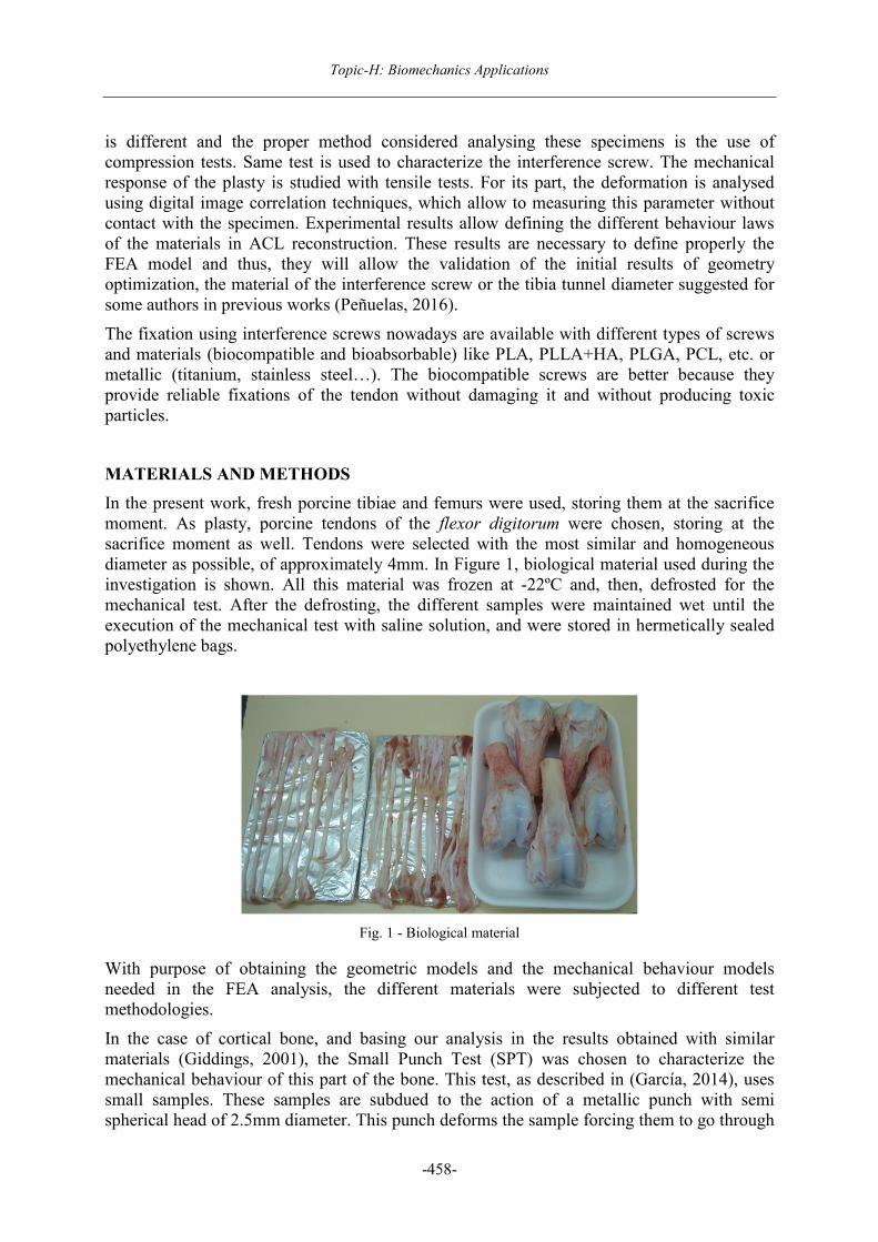
In the present work, fresh porcine tibiae and femurs were used, storing them at the sacrifice moment. As plasty, porcine tendons of the flexor digitorum were chosen, storing at the sacrifice moment as well. Tendons were selected with the most similar and homogeneous diameter as possible, of approximately 4mm. In Figure 1, biological material used during the investigation is shown. All this material was frozen at -22ºC and, then, defrosted for the mechanical test. After the defrosting, the different samples were maintained wet until the execution of the mechanical test with saline solution, and were stored in hermetically sealed polyethylene bags.
Fig. 1 - Biological material
With purpose of obtaining the geometric models and the mechanical behaviour models needed in the FEA analysis, the different materials were subjected to different test methodologies.
In the case of cortical bone, and basing our analysis in the results obtained with similar materials (Giddings, 2001), the Small Punch Test (SPT) was chosen to characterize the mechanical behaviour of this part of the bone. This test, as described in (García, 2014), uses small samples. These samples are subdued to the action of a metallic punch with semi spherical head of 2.5mm diameter. This punch deforms the sample forcing them to go through

Proceedings IRF2018: 6th International Conference Integrity-Reliability-Failure
-459-
a 4mm diameter hole. During the test, load-displacement values are registered. Then, the material characteristic curve could be obtained. It is known that some materials, with similar characteristics as cortical bone, have a quasi-linear elastic behaviour until the sample fracture. The slope of this curve, Pend, divided by the sample thickness, t, could be associated with the elastic modulus of the material by the expression (1):
ξ⋅=t
PendE (1)
where ξ is the characteristic constant of the material. In order to make these tests, little samples of cortical bone were removed using a saw. Some samples are shown in Figure 2(a). Figure 2(b) shows how the sample is placed in the lower device of the test-machine. Figure 3 shows the test, done at 0.2mm/min with the help of a specially designed device for this test, and placed in an MTS static machine with a loading capacity of 5kN. The load-point displacement is obtained with a COD extensometer placed in the device.
Fig. 2 - Cortical bone samples. SPT colocation
Fig. 3 - SPT device
(a) (b)
Topic-H: Biomechanics Applications
-460-
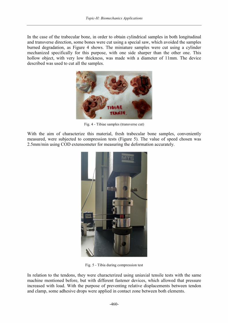
In the case of the trabecular bone, in order to obtain cylindrical samples in both longitudinal and transverse direction, some bones were cut using a special saw, which avoided the samples burned degradation, as Figure 4 shows. The miniature samples were cut using a cylinder mechanized specifically for this purpose, with one side sharper than the other one. This hollow object, with very low thickness, was made with a diameter of 11mm. The device described was used to cut all the samples.
Fig. 4 - Tibiae samples (transverse cut)
With the aim of characterize this material, fresh trabecular bone samples, conveniently measured, were subjected to compression tests (Figure 5). The value of speed chosen was 2.5mm/min using COD extensometer for measuring the deformation accurately.
Fig. 5 - Tibia during compression test
In relation to the tendons, they were characterized using uniaxial tensile tests with the same machine mentioned before, but with different fastener devices, which allowed that pressure increased with load. With the purpose of preventing relative displacements between tendon and clamp, some adhesive drops were applied in contact zone between both elements.

Proceedings IRF2018: 6th International Conference Integrity-Reliability-Failure
-461-
Considering that the main handicap testing soft biological tissues is the impossibility of have accurate deformations, because it is not possible to use contact extensometers (soft tissue experiments large deformations with little load), we decided to use Digital Image Correlation (DIC) techniques. A photogrammetry device GOM model ARAMIS 5M was used. This device allows the measure of surface deformations with no contact with the sample. This equipment records high quality images of the surface analysed during the load application process. Afterwards, these surfaces were evaluated and a three-dimensional digital model of the object is made. Results reliability will depend on the calibration of the device, as well as the choice of the best lens (according to the size of the evaluated zone). In this case, the lens chosen was the ones with 50mm focal distance with a panel calibration type CQCCP20 30x24, which affords a measure zone of 35x29mm.
For the correct working of the equipment, it is necessary that the surfaces evaluated had some reference points with high contrast between them and the surface of study. Thus, and considering that the device records Grey Scale images, a spotted process was done over the tendons with black matte acrylic paint. Figure 6 shows the aspect of the tendons before (a) and after (b) the spotted process.
Fig. 6 - Tendon before and after spotted process
After this process, tensile tests were done with a speed of 20mm/min, considering the end of the test when the tendon break happened. Figure 7, shows the experimental equipment used during the tensile test.
Fig. 7 - Tensile test of the porcine tendon
(b) (a)

Topic-H: Biomechanics Applications
-462-
Interference screws were characterized dimensionally in order to develop the geometric model, as shown in Figure 8.
Fig. 8 - Interference screw (a) 3D model; (b) real
Paying attention to the mechanical behavior, and noticing that there is no material apart from the screws themselves, we realized that it was very difficult to pull out some samples from the screw because of its complicated geometry. So the strategy to follow was to subdue the complete screw under compression tests (Figure 9a) comparing the results obtained from the mechanical test with the ones provided by the FEA model of the same test. The simulation was done with Abaqus, using 2D models and considering both clamps as rigid solids. Assuming the screw material behavior as linear elastic, the elastic modulus of the screw material is estimated by the value where the numeric model has the best adjustment with the load-displacement experimental curve.
Fig. 9 - Compression Test over the screw (a) Experimental; (b) Numeric
RESULTS
With SPT tests done over cortical bone samples (average thickness of 3.9mm), load-displacement curves were obtained as we can see in Figure 10.
(b)
(a)
(b)
(a)

Proceedings IRF2018: 6th International Conference Integrity-Reliability-Failure
-463-
Fig. 10 - Characteristic curve of porcine cortical bone
After the initial zone which corresponds to the indentation of the punch over the bone, the cortical bone behavior is totally linear until its breaking. Figure 11 displays the real aspect of one sample after the test, which shows a total brittle fracture.
Fig. 11 - Cortical bone sample after brittle fracture
Given the fact that coefficient ξ isn’t known for this material (as far as we know, this type of mechanical test is being used for this material for the first time), in order to determine the elastic modulus of the material, a FEA model which simulates the SPT test was done. This FEA model was used successfully with ceramic materials (Quintana, 2017). Considering the cortical bone as a material with linear-elastic behavior, the elastic modulus is calculated as the value for which the numeric model better adjusts the load-displacement experimental curve. This way, the elastic modulus in porcine tibiae tested was 25GPa, very similar to values found in literature for human cortical bone (Dorogoy, 2017), 20GPa. This value was taken as reference because of the similarities between mechanical characteristics in both species (AI Pearce, 2007), and the little information found about porcine bone characteristics.
Compression tests were done over both transversely and longitudinally cut trabecular bone samples. Figure 12 shows one sample under compression test.
Load (N)
Punch displacement (mm)

Topic-H: Biomechanics Applications
-464-
Fig. 12 - Trabecular porcine tibiae during compression test
The characteristic curves are shown in Figure 13. With these curves, mechanical parameters will be obtained for defining this material. As one can observe, and coinciding with other authors approaches (Burstein, 1975), the trabecular bone behavior could be considered as elastic-perfectly plastic. Thus, the mechanical parameters needed will be the elastic modulus (E) and the yield stress (Sy).
Fig. 13 - Strain-deformation curve of Transverse Tibiae
In Table 1, the results obtained from fresh tibiae transversely cut are shown.
Table 1 - Tibiae (transverse cut) compression tests
Test t(mm) d (mm) E (MPa) Sy (MPa)
c1 11.7 11 260.39 6.40
c2 11 11 364.95 6.78
c7 12 10.5x11 368.48 6.84
Average 331.27 6.68
Desvest. 61.41 0.24
It can be deduced that the longitudinal elastic modulus of the transverse porcine tibiae is about 331MPa with a yield strength of 6.7MPa.

Proceedings IRF2018: 6th International Conference Integrity-Reliability-Failure
-465-
In Table 2, data obtained from compression test over longitudinal cut tibiae is shown.
Table 2 - Tibiae (longitudinal cut) compression tests
Test t (mm) d (mm) E (MPa) Sy (MPa)
c4 10 11 124.07 2.8
c5 7 10 79.81 4.4
Average 101.94 3.6
Desvest. 31.29 1.13
With the results above showed, it can be deduced that the transverse elastic modulus of the longitudinal cut porcine tibiae is approximately 102MPa.
Thus, it can be deduced, agreeing with other authors (Wirtz, 2000) that the trabecular bone (in porcine specimens) has three times more elastic modulus in the longitudinal direction than in the transverse direction (transverse and longitudinal cut respectively), so it is more rigid in this direction. It is also different the yield stress value in one and other cut direction, being this value more than the double in the longitudinal direction than in the transverse one. Hence, it has to be noticed the strong anisotropy that presents this material, whose constitutive model must be orthotropic.
In the case of the tendons, the results were extracted from tensile tests. Afterwards, the mathematical model of the material behavior was done for specific soft biological tissues. In order to understand this step, it is important to considerate hyper-elastic deformations in terms of invariants with volumetric and deviatoric response, suggested by other authors (Flory, 1961; Simo, 1991; Weiss, 1996; Holzapfel, 2000; Peña, 2007). Basing the model in bibliographic results and having into account the constitution of the tissue, tendons were modelled as transversely isotropic and longitudinally anisotropic and hyper-elastic behavior. That means, that the collagen fibers that compound these kind of tissues, are in one and unique direction of the tendon, the longitudinal one. This is why the only stress different from zero, and positive (tensile stress) will be the longitudinal stress.
The elastic constitutive laws are usually formulated using the strain energy density function, principally because of the high deformations these kinds of materials experiment. This function depends on the direction the family fibers have at the point X defined by the unit vector m0 (Spencer, 1954). Considering that the movement of the fibers is the same as the points that define the material like a continuous solid, the fibers elongation tensor, λm, defined as the longitudes relation between deformed and reference configuration:
56 7� ∙ 97� (2) Where m0 is the unit vector which defines the fibers direction in the deformed configuration and C=FTF is the Cauchy-Green right tensor, writing F=dx/dX as the transformation Jacobian matrix.
In order to characterize isothermal process (Peña, 2007), only one strain energy density function is postulated. It only depends on the Cauchy-Green right tensor and the fibers direction, m0. � 9,:� �;<= >� ��� 9� ,:�
�;<= >� � �� �1����, �4� � (3)
Topic-H: Biomechanics Applications
-466-
Where φvol (J) y ?� depend on the scalar functions J, @�y M=m0⊗ m0. They describe the isochoric response of the material (Holzapfel, 2000). BC���� is the modified invariant of Cauchy-Green right tensor and BD����, the pseudo-invariant which characterize the fiber constitutive response (Spencer, 1954).
There are different proposals to define the strain energy density function for hyper-elastic materials (isotropic and anisotropic). With isotropic materials, we can find models which are used in different types of biological tissue, for example, the skin (Mooney-Rivlin model). However, all these models cannot reproduce exactly the tendons behavior, materials whose behavior is based on their collagen fibers response.
Considering the fibril-type collagen tissues, that work under tensile conditions (they experiment bending stress when they are under compression loads), and present anisotropy in longitudinal direction (being transversely isotropic), another type of mathematical formulations need to be used. Some formulations can be found inside Abaqus material library, for example, Holzapfel proposal (Holzapfel, 2000). This author suggests a model for collagen fiber materials whose characteristic factors depend on the fibers composition and the material compressibility. However, Holzapfel model was created for Maxwell materials, with simple linear viscoelasticity (series), while other authors (Sasaki,1996; Puxkandl, 2002; Vita, 2005) defend that these type of tissues have a Kelvin-Voigt behavior (parallel viscoelasticity). Thus, the Holzapfel model could be incomplete for these soft tissues. That is why a new optimal model for this material has to be implemented.
Experimental procedure reveals that tendons are materials which have large deformations with low loads. These tissues present a strong no-linearity (Figure 14). Therefore, the proper formulation needs to be found in order to achieve the constitutive material model that better adjust to these requirements, assuming that the tissue is incompressible or quasi- incompressible (Odgen, 2001).
For this purpose, a modified Weiss’s model (Weiss, 1996) is done. The most proper analytical expressions for tendon tissue were obtained. These expressions have been used by Calvo et al. (Calvo, 2009) in previous works.
�� ��� ��� � 3� � ������ (4)
������ 0, � � ! � ����� (5)
������ �3�4#$% & ���'& ������� � �4 �4� � �40������ � 1),
� � * � �����+� � ! � ,-.������� (6)
������ �50�4� � ��623 �4� � � �7,� � * � ,-.������� (7)
The constants c10, c3, c4, c5, c6 y c7 are obtained by fitting experimental data of both tested tendons (Figure14 and Figure 15) applying an error function minimization between experimental stress and analytical stress. � ����� e � ,-.������ are the minimum and maximum values that define the tendon exponential curve.

Proceedings IRF2018: 6th International Conference Integrity-Reliability-Failure
-467-
Table 3 - Tendon behavior model constants
Constants\Tendon Tendon 1 Tendon 2
C10 7.87 7.98
C3 0.001 0.374
C4 77.39 19.24
C5 - -
C6 - -
C7 - -
I40 1.0 1.0
I4ref 1.44 1.44
Fig. 14 - Characteristic curve tendon 1. Tensile test
Fig. 15 - Characteristic curve tendon 2. Tensile test

Topic-H: Biomechanics Applications
-468-
With these values obtained, the material equations were programmed in Matlab® in order to check if tendon data (Table 3) are proper with the formulation chosen to characterize the analyzed material behavior. Since this verification is positive, and the FEA software does not have a proper model to characterize this material, a new subroutine (uanisohyper_inv) was programed in Fortran for Abaqus, having into account that this tendon only has a unique fibers family.
Finally, the interference screw mechanical model was done from compression tests over the screws, from which load-displacement curves were obtained (Figure 16). Comparing now the initial slope in experimental curves with the ones obtained from the numerical model using different values for the elastic modulus, this parameter can be determined like the one which better fits the experimental and the numerical curve. In this case, the elastic modulus postulated was 9.5GPa, very similar to the value proposed by other authors for this type of mixture (PLA+HA) in the same proportions (Jianping, 2006).
Fig. 16 - Characteristic curve interference screw. Compression test
CONCLUSION
The main purpose of this work was the mechanical characterization of each component involved in the ACL reconstruction.
First, using SPT tests, it was possible to characterize the cortical bone in the case of porcine tibiae (biological material used in the study). The characteristic curve of the material was obtained from these tests. This load-displacement data and the numerical model of the test (used with ceramic materials) have allowed determining the elastic modulus of the cortical bone, using the relation between the curve slope and the sample thickness.
With compression test, the elastic modulus and the yield strength values (considering that trabecular bone has an orthotropic behavior) were obtained for the characterization of trabecular bone (both transverse and longitudinal modulus) in the case of porcine tibiae, with the values of E=100MPa and Sy=3.6MPa for the transverse tibiae and E=330MPa and Sy=6.7MPa for the longitudinal ones.

Proceedings IRF2018: 6th International Conference Integrity-Reliability-Failure
-469-
In the case of the tendons, the mechanical method chosen to characterize the material was tensile tests. In order to measure the deformation, DIC techniques were used, which implies that there is no contact between the equipment of deformation measure and the sample tested. After experimental procedure, and using the anisotropic-hyperelastic theoretical model which best represents this tissue behavior, the characteristics coefficients were obtained based on the minimization of the error between experimental and numerical curve. Furthermore, the material was programmed in a subroutine using Fortran language for Abaqus.
Finally, the interference screws were characterized by compression tests, numerically and experimentally. Looking at the results obtained, it can be said that the behavior of the interference screws is linear-elastic with an elastic modulus of 9.5GPa (taking the value which best fits between numerical and experimental curves).
ACKNOWLEDGMENTS
The authors gratefully acknowledge the funding by IUTA (Asturias Technological University Institute), Spain, and our special gratitude to Begoña Calvo Calzada (University of Zaragoza) for her invaluable help.
REFERENCES
[1] C. Quintana, C. Rodríguez, F.J. Belzunce, A.C. Caballero, C. Baudín. Caracterización de materiales cerámicos mediante ensayos miniatura: comparación entre los ensayos SPT y B3B. Anales de mecánica de la Fractura XXXIV. 2017
[2] Peñuelas I., Rodríguez C., Maestro A. Engineering view of the effect of size ratio and type of interference screw used in ACL reconstruction. 17th ESSKA Congress, (The European Society of Sports Traumatology, Knee Surgery and Arthroscopy), Barcelona, Spain, 4-7 May 2016.
[3] V. L. Giddings, S. M. Kurtz, C. W. Jewett, J. R. Foulds, and A. A. Edidin, “A small punch test technique for characterizing the elastic modulus and fracture behavior of PMMA bone cement used in total joint replacement” Biomaterials, vol. 22, no. 13, pp. 1875-1881, 2001.
[4] T. E. García, C. Rodríguez, F. J. Belzunce, and C. Suárez, “Estimation of the mechanical properties of metallic materials by means of the small punch test,” J. Alloys Compd., vol. 582, pp. 708-717, 2014.
[5] A. Dorogoy, D. Rittel, K. Shemtov-Yona, and R. Korabi. Modeling dental implant insertion, J. Mech. Behav. Biomed. Mater., vol. 68, no. January, pp. 42-50, 2017.
[6] AI Pearce, RG Richards, S Milz, E Scheneider, SG Pearce. European Cells and materials Vol.13(2007). pp.1-10. ISSN 1473-2262.
[7] Burstein, A.H., Zika, J.M, Heiple, K.G, Klein, L. Contribution of collagen and mineral to the elastic-plastic properties of bone. Journal Bone Jt Surg.57-A, pp.956-961. 1975.
[8] D.C Wirtz, N. Schiffers, T. Pandorf, K.Radermacher, D. Weichert, R.Forst. Critical evaluation of known bone material properties to realize anisotropic FE-simulation of the proximal femur. J.Biomechanics 33 (2000), pp. 1325-1330.

Topic-H: Biomechanics Applications
-470-
[9] Flory, P.J. “Thermodynamic relations for high elastic materials”. Transactions of the Faraday Society 57, pp. 829-838. 1961.
[10] Simo, J.C., Taylor, R.L. “Quasi-incompressible finite elasticity in principal stretches. Continuum basis and numerical algorithms”. Computer Methods in Applied Mechanics and Engineering 85, pp. 273-310. 1991.
[11] Weiss, J.A., Maker, B.N., Govindjee, S. “Finite element implementation of incompressible, transversely isotropic hyperelasticity”. Computer Methods in Applied Mechanics and Engineering 135, pp. 107-128. 1996.
[12] Holzapfel, G.A., Gasser, T.C., Ogden, R.W. “A new constitutive framework for arterial wall mechanics and a comparative study of material models”. Journal of Elasticity 61, pp. 1-48. 2000.
[13] Peña, E., delPalomar, A.P., Calvo, B., Martinez, M.A., Doblaré, M.”Computational modelling of diarthrodial joints. Physiological, pathological and pos-surgery simulations”. Archives of Computational Methods in Engineering 14 (1), pp. 47-91. 2007.
[14] Spencer, A.J.M. “Theory of invariants. In: Continuum Physics”. Academic Press, New York, pp. 239-253. 1954.
[15] N. Sasaki, S. Odajima. “Stress-strain curve and Young’s modulus of a collagen molecule as determined by X-ray diffraction technique”. J. Biomech., 29 (1996), pp. 655-658
[16] R. Puxkandl, I. Zizak, O. Paris, W. Tesch, S. Bernstorff, P. Purslow, P. Fratzl. “Viscoelastic properties of collagen: synchrotron radiation investigations and structural model”. Philos. Trans. Roy. Soc. Lond. B, 357 (2002), pp. 191-197.
[17] R.D. Vita, W. Slaughter. “A structural constitutive model for the strain rate-dependent behavior of anterior cruciate ligaments”. Int. J. Solids Struct., 43 (2005), pp. 1561-1570.
[18] Ogden, R.W.” Nonlinear Elasticity, Anisotropy, Material Stability and Residual Stresses in Soft Tissue.” Lecture Notes. CISM Course on Biomechanics of Soft Tissue Udine. 2001.
[19] Calvo, B., Peña, E., Martins, P., Mascarenhas, T., Doblaré, M., Jorge, R.N., Ferreira, A. “On modelling damage process in vaginal tissue.” Journal of Biomechanics 42 (5), pp. 642-651. 2009.
[20] F. Jianping, T. Chak-Yin, and T. C.P., “Computation of flexural properties of HA/PLLA composite using a cell model approach,” Acta Mech. Solida Sin., vol. 19, no. 1, pp. 18-25, 2006.