biomechanical analysis of femur with ... - fortune journals
TRANSCRIPT

J Orthop Sports Med 2020; 2 (2): 89-107 DOI: 10.26502/josm.511500024
Journal of Orthopaedics and Sports Medicine 89
Research Article
Biomechanical Analysis of Femur with THA and RHA implants
using CT-Image Based Finite Element Method
Mitsugu Todo1,⃰
, Kosei Fukuoka2
1Research Institute for Applied Mechanics, Kyushu University, kasuga-koen, Kasuga, Fukuoka, Japan
2Interdisciplinary Graduate School of Engineering Sciences, Kyushu University, kasuga-koen, Kasuga, Fukuoka,
Japan
*Corresponding Author: Mitsugu Todo, Associate Professor, Research institute for Applied Mechanics, Kyushu
University 6-1 Kasuga-koen, Kasuga, Fukuoka, Japan, Tel. +81-92-583-7762; E-mail: [email protected]
Received: 3 April 2020; Accepted: 13 April 2020; Published: 16 April 2020
Citation: Mitsugu Todo, Kosei Fukuoka. Biomechanical Analysis of Femur with THA and RHA implants using
CT-Image Based Finite Element Method. Journal of Orthopaedics and Sports Medicine 2 (2020): 89-107.
Abstract
The research demonstrates a novel three-dimensional
finite element analysis to analyze biomechanical
changes in a femur with two different type of hip
prosthesis. The method used principal stress
projections to determine trabeculae trajectories in the
femur. Visual comparisons of the projections of the
femurs show areas of cortical and cancellous changes
due to changes in tensile and compressive stresses,
revealing areas of stress shielding. The method also
included a bone remodeling algorithm to simulate
bone adaptation. In the analysis, a patient-specific
femur model with inhomogeneous material properties
was created from CT images. Maximum load during
walking was simulated with realistic muscle forces,
and stress projections of the femur model were
compared to trabecular trajectories of a real femur for
validation. Bone remodeling was also simulated to
investigate changes in projections over time. High
correlation was found between the principal stress
projections of the computational model and trabeculae
trajectories of a real femur. Changes in projections
were evident for implant models, suggesting stress
shielding and bone remodeling. The analysis provides
an effective method for planning implants that are
ideal for patients and for designing future implants

J Orthop Sports Med 2020; 2 (2): 89-107 DOI: 10.26502/josm.511500024
Journal of Orthopaedics and Sports Medicine 90
that preserves the biomechanics of the femur to
maintain its physiology.
Keywords: Biomechanics; Finite element analysis;
Total hip arthroplasty; Bone remodeling
1. Introduction
Hip arthroplasty is a type of joint replacement surgery
that has been the standard treatment for patients with
osteoarthritis, avascular necrosis, and/or fracture
within the hip joint. The two main surgical procedures
for hip arthroplasty are the total hip arthroplasty
(THA) and the resurfacing hip arthoplasty (RHA),
with the former procedure replacing both the
acetabulum and the femoral head and the latter only
replacing the acetabulum. THA, the more common of
the two procedures, requires three components: a stem
and a spherical head that replaces the femoral head,
and a hemispherical cup with an inner liner to replace
the acetabulum. Stems with an interchangeable neck
component, known as modular implants, are also
available for hip joints with excessive anteversion or
retroversion. RHA also utilizes a hemispherical cup
for the acetabulum, except the femoral component is a
cap that covers, or “resurfaces”, the femoral head.
While fundamental concept of hip arthroplasty has
changed little since its appearance in medicine, the
implants have experienced numerous changes in
terms of material and design [1]. During the early
stages of development, the THA implant had a metal-
on-metal (MOM) bearing combination. All
components were made cobalt-chrome alloy and bone
cement was used to fixate the implant to the bone.
The implant head was also similar in size as the
anatomical head, giving the hip a natural
physiological range of motion (ROM). When it was
revealed that MOM produced high frictional torque,
metal-on-polymer became the popular bearing
combination choice. It soon became evident that
debris from the plastic liner due to volumetric wear
led to osteolysis and causing the implant to loosen.
Thus, the implant head size was reduced to decrease
the wear, which also decreased the ROM of the hip,
limiting the patient’s mobility. The next fifty years
saw the introduction of two more bearing
combinations (ceramic-on-polymer and ceramic-on-
ceramic), though much of the implant designs and the
small head size remained unchanged. This drawback
led to the development of the RHA implant, and re-
introduced the use of MOM. Conservation of bone
stock and increased ROM made RHA implants
popular for younger, more active patients [2].
Presently, hip implants are available in all bearing
combinations and in various shapes and sizes. THA
implants with large head size are also becoming
popular, as researches have shown that with larger
head sizes, lubrication regime changes from boundary
lubrication to fluid-film lubrication [3]. New
researches in materials have also led to bearings
having very low frictional coefficients. In addition,
porous coatings around the stem have led to the
development of cementless implants, providing
stronger bone fixation than using bone cement.
However, there are still risks to hip arthroplasty and
thousands of revision surgery is conducted each year.
The main indications for surgery that concerns the
implant are aseptic loosening, dislocation, and the
wear of acetabular component [4]. The main risk
J Orthop Sports Med 2020; 2 (2): 89-107 DOI: 10.26502/josm.511500024
Journal of Orthopaedics and Sports Medicine 91
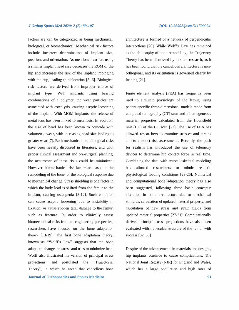
factors are can be categorized as being mechanical,
biological, or biomechanical. Mechanical risk factors
include incorrect determination of implant size,
position, and orientation. As mentioned earlier, using
a smaller implant head size decreases the ROM of the
hip and increases the risk of the implant impinging
with the cup, leading to dislocation [5, 6]. Biological
risk factors are derived from improper choice of
implant type. With implants using bearing
combinations of a polymer, the wear particles are
associated with osteolysis, causing aseptic loosening
of the implant. With MOM implants, the release of
metal ions has been linked to metallosis. In addition,
the size of head has been known to coincide with
volumetric wear, with increasing head size leading to
greater wear [7]. Both mechanical and biological risks
have been heavily discussed in literature, and with
proper clinical assessment and pre-surgical planning,
the occurrence of these risks could be minimized.
However, biomechanical risk factors are based on the
remodeling of the bone, or the biological response due
to mechanical change. Stress shielding is one factor in
which the body load is shifted from the femur to the
implant, causing osteopenia [8-12]. Such condition
can cause aseptic loosening due to instability in
fixation, or cause sudden fatal damage to the femur,
such as fracture. In order to clinically assess
biomechanical risks from an engineering perspective,
researchers have focused on the bone adaptation
theory [13-19]. The first bone adaptation theory,
known as “Wolff’s Law” suggests that the bone
adapts to changes in stress and tries to minimize load.
Wolff also illustrated his version of principal stress
projections and postulated the “Trajectorial
Theory”, in which he noted that cancellous bone
architecture is formed of a network of perpendicular
intersections [20]. While Wolff’s Law has remained
as the philosophy of bone remodeling, the Trajectory
Theory has been dismissed by modern research, as it
has been found that the cancellous architecture is non-
orthogonal, and its orientation is governed clearly by
loading [21].
Finite element analysis (FEA) has frequently been
used to simulate physiology of the femur, using
patient-specific three-dimensional models made from
computed tomography (CT) scan and inhomogeneous
material properties calculated from the Hounsfield
unit (HU) of the CT scan [22]. The use of FEA has
allowed researchers to examine stresses and strains
and to conduct risk assessments. Recently, the push
for realism has introduced the use of telemetry
devices to determine hip contact force in real time.
Combining the data with musculoskeletal modeling
has allowed researchers to mimic realistic
physiological loading conditions [23-26]. Numerical
and computational bone adaptation theory has also
been suggested, following three basic concepts:
alteration in bone architecture due to mechanical
stimulus, calculation of updated material property, and
calculation of new stress and strain fields from
updated material properties [27-31]. Computationally
derived principal stress projections have also been
evaluated with trabeculae structure of the femur with
success [32, 33].
Despite of the advancements in materials and designs,
hip implants continue to cause complications. The
National Joint Registy (NJR) for England and Wales,
which has a large population and high rates of
J Orthop Sports Med 2020; 2 (2): 89-107 DOI: 10.26502/josm.511500024
Journal of Orthopaedics and Sports Medicine 92
coverage, have recently revealed that the revision rate
for MOM implants, specifically RHA implants, was
much higher than other bearing combinations [34,
35]. The findings have led to government health
agencies in England and the United States to release
alerts on the use of particular hip implants.
Furthermore, within the past 10 years, major implant
companies have recalled their implants. While
researches concerning implant design have been
conducted, most have been based on minimizing
mechanical and biological risks. Patient-specific
implants have also been simulated; however, the
advantages have been minor compared to the cost and
time to manufacture such implants [36-40].
Furthermore, long-term safety has not been addressed,
which is a key factor for femur and implant survival,
as well as the quality of life for the patient. Ideally,
there should be minimal differences between the
biomechanics of an intact femur and that of a femur
with implant. Any alterations in loading will affect the
stress and strain distribution, which will cause
respective changes in the trabecular structure and
henceforth the bone density. Thus, the primary design
criteria of an implant must be based on minimizing
biomechanical risks, followed by the minimization of
mechanical and biological risks. In order to assess the
effectiveness and safety of the implant design, it is
necessary to first replicate the biomechanics of the
femur, test under realistic physiological conditions,
followed by bone remodeling simulation to predict
long-term outcome. To the best of our knowledge, the
combination of the three works has not yet been
reported in literature. The goal of this research was to
investigate whether FEA and computational
simulations of human physiology can be utilized to
assess implant designs and formulate design criteria
for future implant design. The objectives of this study
were to realistically simulate the physiological
condition of the femur, to investigate the effects of an
implant in the femur, and to simulate long-term
effects.
2. Finite Element Modeling
2.1 3D models
CT scans (512 x 512, 1 mm slices) from a male 54yo
patient were used to make an intact bone model.
MECHANICAL FINDER 6.1 (Research Center of
Computational Mechanics Inc., Japan) (MF) was used
to trace region of interest (ROI) around the outer
cortical region on the scans to obtain the anatomical
structure of the left femur. The ROIs were then stacked
and the gaps between the CT scans were automatically
conjoined by the software to create a femur volume.
The volume was surface meshed (unstructured linear
triangular mesh) using ANSYS ICEM CFD v13
(ANSYS Inc., USA). Rapidform XOR3 (INUS
Technology Inc., USA) was used to smooth the
meshed model, and FEMAP 10.1.1 (Siemens PLM
Software, USA) was used for all editing made on the
meshed model. The final volume was remeshed
(unstructured linear tetrahedral mesh) in MF as shown
in (Figure 1). CAD models of THA and RHA implant
were directly imported into MF. RHA model
consisted of a 48 mm ⌀ cap, identical to the size of the
patient’s femoral head as shown in (Figure 2). A bone
cement model of two-millimeter thickness was
created for the RHA implant model and fitted between
the implant and the femoral head. THA implant
consisted of a 156 mm length stem and a 34 mm ⌀
head. All models were meshed with linear

J Orthop Sports Med 2020; 2 (2): 89-107 DOI: 10.26502/josm.511500024
Journal of Orthopaedics and Sports Medicine 93
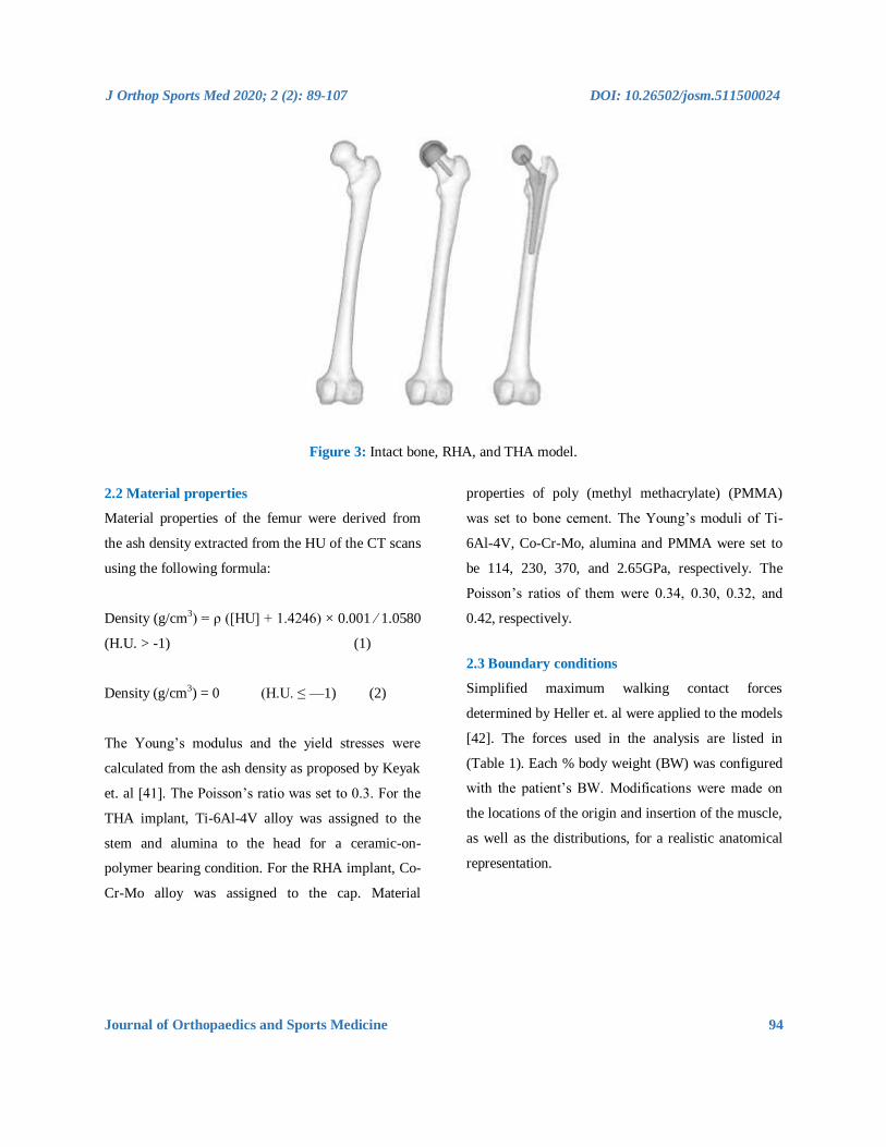
unstructured tetrahedral mesh. The intact bone models
were then grinded so that those implants were inserted
into the bone models as shown in (Figure 3).
Figure 1: Intact bone model.
(a) THA implant, ball and stem.
(b) RHA implant, head and bone cement.
Figure 2: THA and HRA implants.
J Orthop Sports Med 2020; 2 (2): 89-107 DOI: 10.26502/josm.511500024
Journal of Orthopaedics and Sports Medicine 94
Figure 3: Intact bone, RHA, and THA model.
2.2 Material properties
Material properties of the femur were derived from
the ash density extracted from the HU of the CT scans
using the following formula:
Density (g/cm3) = ρ ([HU] + 1.4246) × 0.001 ⁄ 1.0580
(H.U. > -1) (1)
Density (g/cm3) = 0 (H.U. ≤ —1) (2)
The Young’s modulus and the yield stresses were
calculated from the ash density as proposed by Keyak
et. al [41]. The Poisson’s ratio was set to 0.3. For the
THA implant, Ti-6Al-4V alloy was assigned to the
stem and alumina to the head for a ceramic-on-
polymer bearing condition. For the RHA implant, Co-
Cr-Mo alloy was assigned to the cap. Material
properties of poly (methyl methacrylate) (PMMA)
was set to bone cement. The Young’s moduli of Ti-
6Al-4V, Co-Cr-Mo, alumina and PMMA were set to
be 114, 230, 370, and 2.65GPa, respectively. The
Poisson’s ratios of them were 0.34, 0.30, 0.32, and
0.42, respectively.
2.3 Boundary conditions
Simplified maximum walking contact forces
determined by Heller et. al were applied to the models
[42]. The forces used in the analysis are listed in
(Table 1). Each % body weight (BW) was configured
with the patient’s BW. Modifications were made on
the locations of the origin and insertion of the muscle,
as well as the distributions, for a realistic anatomical
representation.

J Orthop Sports Med 2020; 2 (2): 89-107 DOI: 10.26502/josm.511500024
Journal of Orthopaedics and Sports Medicine 95
Type of load Forces (N)
Intersegmental resultant 483.19
Abductor 632.30
Tensor fascia late, proximal 115.20
Tensor fascia latae, distal 115.38
Vastus lateralis 574.64
Table1: Physiological loading during walking.
Simplified abductor muscles were expanded to
include gluteus medius, gluteus minimus, and gluteus
maximum to the correct anatomical position and
distribution as shown in (Figure 4). The porous
coating on the upper half of the implant was assumed
to be fully bonded with the bone (Figure 5). Non-
porous areas were assumed to have a friction
coefficient of 0.2. In the case of RHA, contact options
between the implant and bone cement, and between
the bone cement and bone was considered, set at 0.3
and 0.5, respectively. Fixed constraint was applied to
the distal femur.
Figure 4: Walking contact force.
Intersegmental resultant = green | muscle = red | constraint = blue.

J Orthop Sports Med 2020; 2 (2): 89-107 DOI: 10.26502/josm.511500024
Journal of Orthopaedics and Sports Medicine 96
Figure 5: Contact option applied to implants.
2.4 Bone adaptation algorithm
Bone adaptation algorithm proposed by Huiskes et. al
was used in this experiment [43]. In the theoretical
formulation, the rate of remodeling as the change of
Young’s modulus, dE/dt, was correlated with the
strain energy density, U, as follows:
dE = C(U Un ) (3)
dt
Where C and Un are the remodeling constant and the
site specific homeostatic equilibrium strain energy
density, respectively. In the present analysis, C and
Un were set at 1.2×10⁵ and 0.011MJ/m3
,
respectively.
3. Results
3.1 Principal stress projections of intact model
Preliminary principal stress projections predicted by
FEA were compared to the CT scan of the patient as
shown in (Figure 6). In the CT scan, a distinct
hypodense structure can be seen from the top of the
femoral head tracing downwards to the calcar
femorale of the femur. This is represented as the
minimum principal stress (red) on the FEA result. The
epiphyseal line can also be seen in the CT scan, near
the center of the femoral head. This is traceable by the
maximum principal stress (blue). With the FEA result,
it is also possible to view the five trabeculae groups:
principal tensile and compressive group (dashed),
secondary tensile and compressive group (dotted),
and the greater trochanter group (Figure c). When the
groups are superimposed, the patterns reveal Ward’s
Triangle (W), the area with the minimum bone
density. In addition, the projections indicate that the
trabeculae do not form a network of perpendicular
intersections, as postulated in the Trajectory Theory.

J Orthop Sports Med 2020; 2 (2): 89-107 DOI: 10.26502/josm.511500024
Journal of Orthopaedics and Sports Medicine 97
W
(a) Principal stress projection (b) Corresponding CT image
(c) Five trabeculae groups.
Figure 6: Coronal principal stress projection, patient CT image and five trabecular groups.
(Figure 7) shows the principal stress projection in the
transverse plane. It is possible to see both the
epiphyseal line and the calcar femoral, that are very
similar to the real anatomical structure of femur.
These similarities between the FEA results and the
real femoral structure indicate that 3D FEA can
Max. Principal
Min. Principal

J Orthop Sports Med 2020; 2 (2): 89-107 DOI: 10.26502/josm.511500024
Journal of Orthopaedics and Sports Medicine 98
realistically predict trabeculae structure due to the
stress projections being determined from material
properties and not the symmetry. The intact bone was
attested to be an appropriate control for the
experiment.
\
Max. Principal
Min. Principal
Figure 7: Principal stress projection in transverse plane.
3.2 Principal stress projections of THA and RHA
models
The preliminary HRA projections show similar
characteristics to the intact bone model as shown in
(Figure 8). Much of the trabeculae groups remained,
with little change in the greater trochanter region.
However, the diaphysis show decrease in stress
projections. It is also possible to see a collection of
stress projections near the tip of the stem, despite the
stem superimposing Ward’s triangle. While the
overall trabecular structure may have become sparse
with the insertion of the implant, much of the
trabecular characteristics are maintained.
None of the trabeculae groups remain in the THA
model due to the absence of the femoral head. While
the intact bone model indicates pure compressive
loading along the medial region, the calcar femorale
region shows tensile loading. Contrastingly, the
lateral region shows increase in minimum principal
stresses, indicating high compressive loading and
densification of the trabeculae near the middle of the
stem. Like the RHA model, the greater trochanter
region does not significantly change regarding
projection.

J Orthop Sports Med 2020; 2 (2): 89-107 DOI: 10.26502/josm.511500024
Journal of Orthopaedics and Sports Medicine 99
Figure 8: Preliminary principal stress projection (intact bone, THA, RHA).
3.3 Distribution of equivalent stress in THA and
RHA models
To assess the post-operative safety of the implant, the
equivalent stress distribution of each model was
investigated and compared to the intact bone model.
Drucker-Prager yield criterion was chosen as bone is
a brittle material and the compressive strength is
higher than the tensile strength [44, 45]. In addition,
excluding the RHA and THA models, implant designs
with high stress and wide distribution were assumed
to be deficient and were omitted from further
experimentation. The equivalent stress for RHA
shows almost identical distribution as the intact bone
model as shown in (Figure 9). THA model equivalent
stress distribution reveal that the proximal lateral
section experiences high stress, while the distal lateral
section experiences low stress. However, the stress
increases around the implant tip. Proximal medial
region, around the porous coating of the implant, also
experiences high stress, although it appears to decrease
distally.

J Orthop Sports Med 2020; 2 (2): 89-107 DOI: 10.26502/josm.511500024
Journal of Orthopaedics and Sports Medicine 100
Figure 9: Drucker-Prager equivalent stress (intact bone, THA, RHA).
3.4 Bone remodeling behavior
Preliminary inspection is important to inspect the
changes in the physiology of post-operative femur,
but so far, only the mechanical aspects (i.e. results
based on material properties) have been considered. In
order to assess post-operative conditions and long-
term outcomes, bone remodeling simulation is
required. Bone remodeling was conducted on the
THA and RHA implants. The intact bone model was
not simulated for bone remodeling due to the
assumption that, excluding critical health conditions,
there is no significant change in bone structure for the
given time that implanted femurs reach steady state
(i.e., no further bone remodeling occurs). Thus, all
implant models were remodeled until steady state was
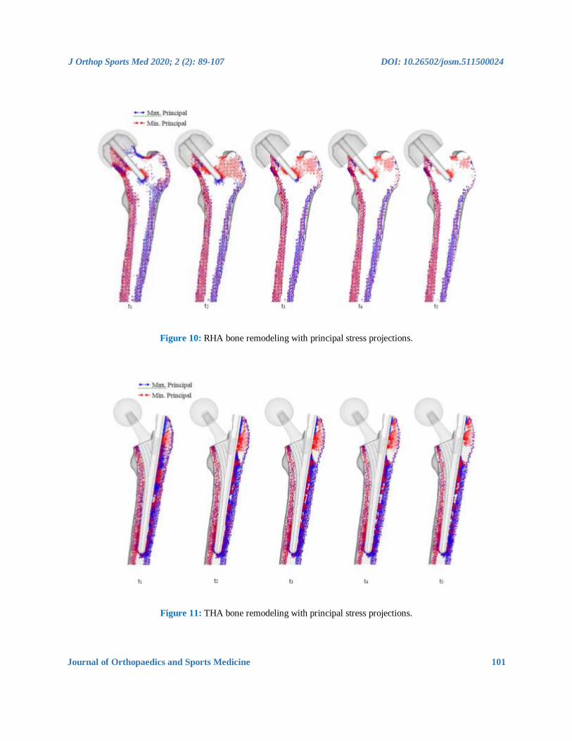
reached. The results for the RHA implant are shown
in (Figure 10). Significant changes occur in the
femoral head, as the disappearance of trabeculae
groups causes formations of an unnatural trabeculae
group. At t1, the disappearance of primary
compressive group at the top half of the femoral head
can be seen, and whole of the bottom half being
directed from the implant stem. A collection of
projections can also be seen near the calcar femoral.
Much of the primary tensile group has disappeared, as
well as both secondary groups.
As seen in the preliminary stress projection, a
collection of projections exists around the tip of the
stem. At t2, all trabeculae groups have disappeared,
and a formation of a new compressive group,
projecting from the stem towards the greater
trochanter can be seen. As the modeling enters steady
state, the femoral head is absent of distinct
projections; however, region around the calcar
femorale and the stem tip contains stress projections,
and both medial and lateral stress projections have
remained.
J Orthop Sports Med 2020; 2 (2): 89-107 DOI: 10.26502/josm.511500024
Journal of Orthopaedics and Sports Medicine 101
Figure 10: RHA bone remodeling with principal stress projections.
Figure 11: THA bone remodeling with principal stress projections.

J Orthop Sports Med 2020; 2 (2): 89-107 DOI: 10.26502/josm.511500024
Journal of Orthopaedics and Sports Medicine 102
The significant change with the THA implant model
is the restoration of the medial and lateral projections,
as well as the projections at the calcar femorale,
which has changed back to compressive projections as
shown in (Figure 11). Collections of projections still
remain along the surface of the implant and stem tip,
and continues until the remodeling reaches steady
state. A clear area without projections also appears
beneath the greater trochanter.
3.5 Bone mineral density
Bone mineral density (BMD) was analyzed to link
projections to trabeculae structure and the results are
shown in (Figure 12). For implant models, this was
calculated at t5, or the steady state stage. BMD of the
intact bone was directly derived from the CT scans.
From the BMD, the quality of the bone stock can be
determined, which reflects on the strength of the bone
as well as areas which may become the focal point for
risks. Areas of high BMD correlates to high stress
and/or stress shielding, and areas of low BMD reveals
weakening of the bone and potential risk triggers.
Like the stress projections, the BMD distribution is
very similar to the intact bone. The diaphysis has
maintained BMD on both the medial and lateral
regions. However, there is a significant decrease in
density in the femoral head. The distributions show
that BMD is low around the porous coating, and high
around the uncoated region. The stem tip also shows
increased BMD. The shorter length model has a larger
distribution in which density has increased. The stem
tip on the larger headed implant, on the other hand,
does not show signs of increased BMD.
Figure 12: Bone mineral density after bone remodeling.

J Orthop Sports Med 2020; 2 (2): 89-107 DOI: 10.26502/josm.511500024
Journal of Orthopaedics and Sports Medicine 103
4. Discussion
The preliminary principal stress projections showed
that RHA implants are superior in design as the
trabecular groups were maintained and the diaphysis
was under the correct loading. This indicated that
upon initial loading, RHA implants could maintain
the same trabeculae structure the femur had before
arthroplasty. The Drucker-Prager equivalent stress
distributions also had similar results. The distribution
of the RHA implant was comparable to that of the
intact bone. At first glance, it appears that the RHA is
inferior to the THA implant design, but in reality this
is not the case. Inspecting the biological aspects, bone
remodeling revealed a contradicting yet realistic
result. Due to the RHA implant supporting much of
the load, stress projections gradually diminished,
indicating increase in cancellous region in the femoral
head. Furthermore, due to the location of the stem,
there are indications of bone densification in Ward’s
triangle, an area known to have low strength,
consisting only of cancellous structure. Newly formed
trabeculae structures fanning from the stem to the
greater trochanter also indicates unnatural trabeculae
growth. BMD results also indicate a decrease in
density in the femoral neck. While the diaphysis
remains strong (stronger than the THA models), the
weakening of the femoral neck is inevitable. It clearly
shows that the upper region of the femoral head has
minimum support. From these findings it is easy to
understand why femoral neck fracture is common for
RHA implants. THA implants showed significant
changes in the trabeculae structure in the preliminary
experiment which was able to maintain the
characteristics of the diaphysis. When the Drrucker-
Prager equivalent stress was inspected, THA models
revealed extremely high stress areas around the
proximal region. Again, the distributions of the larger
head-sized implant were akin to the intact bone
model.
While bone remodeling simulation has revealed that
the diaphysis returns to its original state, the lateral
proximal region, below the greater trochanter, and the
tip of the implant stem, remains to be an issue. This
finding was also reflected with the BMD analysis,
where increased bone density was found in identical
locations. Such characteristics where two highly
densified areas separated by low density region could
lead to peri-prosthetic fracture. In all cases, the
implant closely matched the results of the intact bone
model. The main simulation limitation is the use of
linear tetrahedral elements. For FEA, quadratic
tetrahedral elements, or, if computationally possible,
linear hexahedral or quadratic hexahedral should be
used, as linear tetrahedral elements have been known
to be too stiff due to lower degrees of freedom, which
could produce unrealistic results. Furthermore,
recent bone adaptation algorithms have included the
effect of stimulus on a cellular level, specifically
the effect of mechanical stimulus on the osteocyte.
This leads to the importance of dynamic loading, not
static loading, as used in this experiment. Such use
of algorithms would further realistically simulate
bone adaptation. In addition, modeling real muscle
tissue and not musculoskeletal loading will further
amplify realistic femur physiology. In addition, the
main experimental limitation is the small sample
size, for only a single patient’s CT scan was used
throughout the experiment. While increasing the
number of patient data will reveal trends, the result
J Orthop Sports Med 2020; 2 (2): 89-107 DOI: 10.26502/josm.511500024
Journal of Orthopaedics and Sports Medicine 104
will always be patient-specific. It should be noted that
that true validation for implant designs is derived
from case studies, where the subject’s age, sex,
and gender, as well as the implant size, material,
and bearing combination play an important role.
Clinical studies must also be considered, where the
patient’s health, the condition of the femur, and the
skill and experience of the surgeon are important
factors. Furthermore, the number of such studies will
also reflect the validity of research. Despite of this,
the research has closely achieved clinical results with
engineering methodology. It has also shown that
mechanical assessment is not enough to effectively
evaluate the implant. Biomechanical assessment must
be conducted to fully establish the safety of a design.
5. Conclusions
A novel process to realistically simulate long-term
biomechanics of femur with implants has been
proposed. FEA has provided to be an integral tool to
realistically model the biomechanics of the femur,
with the use of realistic physiological loading
conditions. Computational modeling of bone
adaptation has also predicted the long-term
physiological outcome of a femur with implant, and
conducting risk assessments have revealed possible
fracture areas due to long-term remodeling. Using this
process, implant designers can investigate the femur
physiology of design, and determine long-term effects
by performing bone adaptation and risk assessment,
before the design enters production. Medical doctors
can also benefit from this process during pre-
operative planning stage. An ideal implant can be
chosen purely from the patient’s femur’s
biomechanics, and long-term assessments can
estimate when post-operative follow-up should be
performed before serious damages occur.
References
1. Gomez PF, Morcuende JA, Early attempts at hip
arthroplasty- 700s TO 1950s.The Iowa
Orthopaedic Journal 25 (2005): 25-29.
2. Shrader MW, Bhowmik-Stoker M, Jacofsky
MC, et al. Gait and stair function in total and
resurfacing hip arthroplasty: a pilot study.
Clinical orthopaedics and related research 467
(2009): 1476-1484.
3. Dowson D, Hardaker C, Flett M, et al. A hip
joint simulator study of the performance of
metal-on-metal joints. The Journal of
Arthroplasty 19 (2004): 124-130.
4. Porter M, Tucker K, Beaumont R, et al. National
Joint Rgistry for England and Wales 9th Annual
Report (2012).
5. Malik A, Maheshwari A, Dorr LD. Impingement
with total hip replacement. The Journal of bone
and joint surgery. American volume 89 (2007):
1832-1842.
6. Kelley SS, Lachiewicz PF, Hickman JM, et al.
Relationship of femoral head and acetabular size
to the prevalence of dislocation. Clinical
orthopaedics and related research 355 (1998):
163-170.
7. Lavigne M, Ganapathi M, Mottard S, et al.
Range of motion of large head total hip
arthroplasty is greater than 28 mm total hip
arthroplasty or hip resurfacing. Clinical
biomechanics (Bristol, Avon) 26 (2011): 267-
273.
8. Joshi MG, Advani SG, Miller F, et al. Analysis
J Orthop Sports Med 2020; 2 (2): 89-107 DOI: 10.26502/josm.511500024
Journal of Orthopaedics and Sports Medicine 105
of a femoral hip prosthesis designed to reduce
stress shielding. Journal of biomechanics 33
(2000): 1655-1662.
9. Abdullah AH, Asri MNM, Alias MS et al. Finite
Element Analysis of Cemented Hip
Arthroplasty : Influence of Stem Tapers, in
Proceedings of the International
MultiConference of Engineers and Computer
Scientists 3 (2010).
10. Behrens B, Wirth CJ, Windhagen H, et al.
Numerical investigations of stress shielding in
total hip prostheses. Proceedings of the
Institution of Mechanical Engineers, Part H:
Journal of Engineering in Medicine 222 (2008):
593-600.
11. Abdullah AH, Nor MAM, Saman AM. Stress
and Strain Distribution in Cemented Total Hip
Arthroplasty for Walking Load Case in 2009
International Conference on Computer
Technology and Development (2009): 260-263.
12. Ridzwan MIZ, Shuib S, Hassan AY, et al.
Ridzwan, MIZ - Problem of Stress Shielding and
Improvement to the Hip Implant DesignA
Review. Journal of Medical Sciences 7 (2007):
460-467.
13. Kowalczyk P. Simulation of orthotropic
microstructure remodelling of cancellous bone.
Journal of biomechanics 43 (2010): 563-569.
14. Garcia JM, Doblare M, Cegonino J. Bone
remodelling simulation : a tool for implant
design. Computational Materials Science 25
(2002): 100-114.
15. Herrera A, Panisello JJ, Ibarz E, et al. Long-term
study of bone remodelling after femoral stem: a
comparison between dexa and finite element
simulation. Journal of biomechanics 40 (2007):
3615-3625.
16. Scannell PT, Prendergast PJ. Cortical and
interfacial bone changes around a non-cemented
hip implant: simulations using a combined
strain/damage remodelling algorithm. Medical
engineering and physics 31 (2009): 477-488.
17. Belinha J, Natal Jorge RM, Dinis LMJS. Bone
tissue remodelling analysis considering a radial
point interpolator meshless method. Engineering
Analysis with Boundary Elements 36 (2012):
1660-1670.
18. Kerner J, Huiskes R, van Lenthe GH, et al.
Correlation between pre-operative periprosthetic
bone density and post-operative bone loss in
THA can be explained by strain-adaptive
remodelling. Journal of biomechanics 32 (1999):
695-703.
19. Waide V, Cristofolini L, Stolk J, et al.
Experimental investigation of bone remodelling
using composite femurs. Clinical Biomechanics
18 (2003): 523-536.
20. Skedros JG, a Brand R. Biographical sketch:
Georg Hermann von Meyer (1815-1892).
Clinical orthopaedics and related research 469
(2011): 3072-3076.
21. Skedros JG, Baucom SL. Mathematical analysis
of trabecular trajectories in apparent trajectorial
structures: the unfortunate historical emphasis on
the human proximal femur. Journal of theoretical
biology 244 (2007): 15-45.
22. Keyak JH, a Rossi S, a Jones K, et al. Prediction
of femoral fracture load using automated finite
element modeling. Journal of biomechanics 31
(1998): 125-133.

J Orthop Sports Med 2020; 2 (2): 89-107 DOI: 10.26502/josm.511500024
Journal of Orthopaedics and Sports Medicine 106
23. Bergmann G, Graichen F, a Rohlmann, et al.
Realistic loads for testing hip implants. Bio-
medical materials and engineering 20 (2010):
65-75.
24. Bergmann G, Deuretzbacher G, Heller M, et al.
Hip contact forces and gait patterns from routine
activities. Journal of biomechanics 34 (2001):
859-871.
25. Simoes JA, Vaz MA, Blatcher S, et al. Influence
of head constraint and muscle forces on the
strain distribution within the intact femur.
Medical engineering and physics 24 (2002): 243.
26. Bitsakos C, Kerner J, Fisher I, et al. The effect
of muscle loading on the simulation of bone
remodelling in the proximal femur. Journal of
biomechanics 38 (2005): 133-139.
27. Fyhrie D, Schaffler M. The adaptation of bone
apparent density to applied load. Journal of
biomechanics 28 (1995): 135-146.
28. Weinans H, Huiskes R, Grootenboer HJ. Effects
of material properties of femoral hip components
on bone remodeling. Journal of orthopaedic
research 10 (1992): 845-853.
29. Turner CH, Anne V, Pidaparti RM. A uniform
strain criterion for trabecular bone adaptation: do
continuum-level strain gradients drive
adaptation? Journal of biomechanics 30 (1997):
555-563.
30. Mullender M, van Rietbergen B, Rüegsegger P,
et al. Effect of mechanical set point of bone cells
on mechanical control of trabecular bone
architecture. Bone 22 (1998): 125-131.
31. Huiskes R, Weinans H, Grootenboer HJ.
Adaptive bone-remodeling theory applied to
prosthetic-design analysis. Journal of … 20
(1987): 1135-1150.
32. San Antonio T, Ciaccia M, Müller-Karger C, et
al. Orientation of orthotropic material properties
in a femur FE model: a method based on the
principal stresses directions. Medical
engineering and physics 34 (2012): 914-919.
33. Dick C, Georgii J, Burgkart R, et al. Stress
tensor field visualization for implant planning in
orthopedics. IEEE transactions on visualization
and computer graphics 15 (2009): 1399-1406.
34. Smith AJ, Dieppe P, Vernon K, et al. Failure
rates of stemmed metal-on-metal hip
replacements: analysis of data from the National
Joint Registry of England and Wales. Lancet 379
(2012): 1199-1204.
35. Smith AJ, Dieppe P, Howard PW, et al. Failure
rates of metal-on-metal hip resurfacings:
analysis of data from the National Joint Registry
for England and Wales. Lancet 380 (2012):
1759-1766.
36. Chang PB, Robie BH, Bartel DL. Preclinical
cost analysis of orthopaedic implants: a custom
versus standard cementless femoral component
for revision total hip arthroplasty. Journal of
biomechanics 32 (1999): 1309-1318.
37. Baleani M, Viceconti M, Muccini R, et al.
Endurance verification of custom-made hip
prostheses. International Journal of Fatigue 22
(2000): 865-871.
38. Bert JM. Custom total hip arthroplasty. The
Journal of arthroplasty 11 (1996): 905-915.
39. Götze C, Steens W, Vieth V, et al. Primary
stability in cementless femoral stems: custom-
made versus conventional femoral prosthesis.
Clinical biomechanics (Bristol, Avon) 17
J Orthop Sports Med 2020; 2 (2): 89-107 DOI: 10.26502/josm.511500024
Journal of Orthopaedics and Sports Medicine 107
(2002): 267-273.
40. Kawate K, Ohneda Y, Ohmura T, et al.
Computed tomography-based custom-made stem
for dysplastic hips in Japanese patients. The
Journal of arthroplasty 24 (2009): 65-70.
41. Keyak, a Rossi S, a Jones K, et al. Prediction of
femoral fracture load using automated finite
element modeling. Journal of Biomechanics 31
(1998): 125-133.
42. Heller M, Bergmann G, Kassi JP. Determination
of muscle loading at the hip joint for use in pre-
clinical testing. Journal of Biomechanics 38
(2005): 1155-1163.
43. Huiskes R, Weinans H, Grootenboer HJ.
Adaptive bone-remodeling theory applied to
prosthetic-design analysis. Journal of
Biomechanics 20 (1987): 113 5-1150.
44. Bessho M, Ohnishi I, Matsuyama J, et al.
Prediction of strength and strain of the proximal
femur by a CT-based finite element method.
Journal of biomechanics 40 (2007): 1745-1753.
45. Wakao N, Harada A, Matsui Y, et al. The effect
of impact direction on the fracture load of
osteoporotic proximal femurs. Medical
engineering and physics 31 (2009): 1134–1139.
This article is an open access article distributed under the terms and conditions of the
Creative Commons Attribution (CC-BY) license 4.0