bioinspired materials for water supply and management: water
TRANSCRIPT

rsta.royalsocietypublishing.org
ReviewCite this article: Brown PS, Bhushan B. 2016Bioinspired materials for water supply andmanagement: water collection, waterpurification and separation of water from oil.Phil. Trans. R. Soc. A 374: 20160135.http://dx.doi.org/10.1098/rsta.2016.0135
Accepted: 21 April 2016
One contribution of 12 to a theme issue‘Bioinspired hierarchically structured surfacesfor green science’.
Subject Areas:nanotechnology, materials science, biomedicalengineering, physical chemistry
Keywords:biomimetics, water, fog harvesting,desalination, purification, separation
Author for correspondence:Bharat Bhushane-mail: [email protected]
Bioinspired materials for watersupply and management:water collection, waterpurification and separation ofwater from oilPhilip S. Brown and Bharat Bhushan
Nanoprobe Laboratory for Bio- and Nanotechnology andBiomimetics (NLBB), The Ohio State University, 201 W. 19th Avenue,Columbus, OH 43210-1142, USA
PSB, 0000-0001-5390-5098; BB, 0000-0001-7161-6601
Access to a safe supply of water is a human right.However, with growing populations, global warmingand contamination due to human activity, it is one thatis increasingly under threat. It is hoped that nature caninspire the creation of materials to aid in the supplyand management of water, from water collectionand purification to water source clean-up andrehabilitation from oil contamination. Many speciesthrive in even the driest places, with some survivingon water harvested from fog. By studying thesespecies, new materials can be developed to providea source of fresh water from fog for communitiesacross the globe. The vast majority of water on theEarth is in the oceans. However, current desalinationprocesses are energy-intensive. Systems in our ownbodies have evolved to transport water efficientlywhile blocking other molecules and ions. Inspirationcan be taken from such to improve the efficiency ofdesalination and help purify water containing othercontaminants. Finally, oil contamination of water fromspills or the fracking technique can be a devastatingenvironmental disaster. By studying how naturalsurfaces interact with liquids, new techniques can bedeveloped to clean up oil spills and further protect ourmost precious resource.
This article is part of the themed issue ‘Bioinspiredhierarchically structured surfaces for green science’.
2016 The Author(s) Published by the Royal Society. All rights reserved.
on June 28, 2016http://rsta.royalsocietypublishing.org/Downloaded from

2
rsta.royalsocietypublishing.orgPhil.Trans.R.Soc.A374:20160135
.........................................................
1. Introduction‘The human right to water entitles everyone to sufficient, safe, acceptable, physically accessibleand affordable water for personal and domestic uses’ [1].
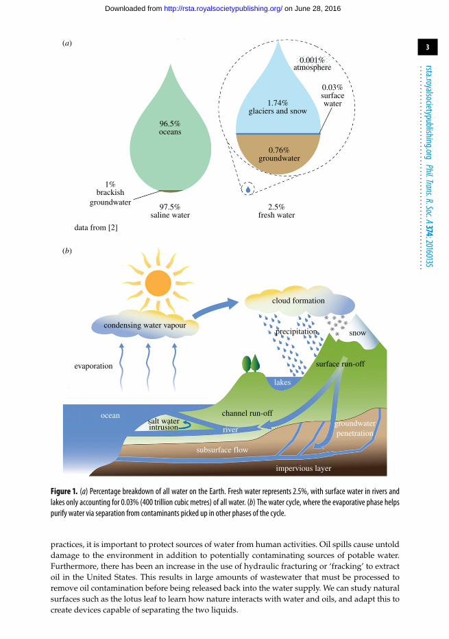
Water is a vital resource upon which our survival depends. Water covers 70% of the Earth’ssurface; however, at any one time the vast majority of water is contained in the oceans, withfresh water accounting for only 2.5% of all water (figure 1a). Water continuously moves in a cyclebecause of evaporation, condensation, precipitation, surface and channel run-off, and subsurfaceflow (figure 1b). The evaporative phase can help purify water by separating it from contaminantspicked up in other phases of the cycle, including salt in the oceans. Of the 2.5% fresh water, themajority is trapped as glaciers and snow (1.74% in total) while only 0.79% (11 quadrillion cubicmetres) of all water is found in lakes, rivers and as groundwater (which itself accounts for 0.76%in total; figure 1a) [2]. The distribution of this water is not uniform across the world, with around20% of the world’s surface fresh water found in the North American Great Lakes [3].
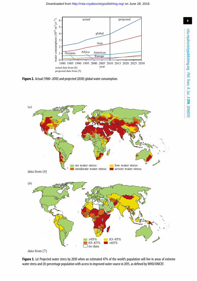
With global warming leading to increased drought periods, it is becoming apparent that ourcurrent supply of fresh water must be supplemented if our future needs are to be met. Globalwater consumption is expected to reach 6 trillion cubic metres a year by 2030 as the populationmoves towards a projected 8.2 billion [4,5] (figure 2). These challenges will mean that more freshwater sources will be under increased stress as demand outstrips supply (figure 3a). The numberof people living in areas affected by severe water stress is expected to increase from 2.8 billionin 2005 to 3.9 billion by 2030, representing over 47% of the projected population [4]. While themajority of these people will live in South Asia, the Middle East and North Africa, global warmingwill probably offset efficiency gains made in industrial sectors in countries such as the UnitedStates.
In addition, despite progress during the last decade thanks to the ‘UN Water for Life’ initiative,access to water also remains an issue for some of the poorest countries, with 1 in 10 people still nothaving access to an improved water source (figure 3b). An improved water source is defined asone likely to be protected from outside contamination, and includes water piped into a dwellingor yard, public tap, borehole, protected dug well, protected spring and collected rainwater [7].However, although a water source may be classified as ‘improved’, it is not necessarily safefor human consumption [8]. There are still many people in the world who do not know wheretheir next drink of clean water will come from. These communities stand to benefit the mostfrom advances in the science and engineering of materials and devices for water supply andmanagement.
All living things require water. Therefore, it is no surprise that, after some 3 billion yearsof evolution, many species exhibit efficient solutions to ensure their water security [9]. Thesesolutions typically involve species possessing unique chemistry and structuring on or within theirbody that help to dictate the movement of water.
For instance, many plant and animal species in arid regions rely on their ability to collectwater from fog. By studying the chemistry and structures involved, it is possible to create artificialfog harvesters to provide a supplemental water source for communities in regions where fog iscommon, such as coastal regions of the western United States, South America and western Africa.
Another source of water would be the saline water found in the oceans, which accountfor over 96.5% of all water on the planet (plus a further 1% found in brackish groundwater).However, water purification, especially desalination, where saline water is made fit for humanconsumption [10], remains an energy-intensive process [11]. Systems in our own body are capableof filtering water, removing organics and ionic species with high water permeabilities and at lowenergy cost. Incorporation, adaptation or replication of the biological structures involved couldenable creation of more efficient water purification membranes for the conversion of seawaterinto a regular source of fresh water. Purification membranes can also help to ensure that othersources of water remain safe for human consumption.
Finally, in an age of high-profile industrial accidents such as the Deepwater Horizon in theGulf of Mexico, in addition to contamination of groundwater sources due to unsafe oil disposal
on June 28, 2016http://rsta.royalsocietypublishing.org/Downloaded from
3
rsta.royalsocietypublishing.orgPhil.Trans.R.Soc.A374:20160135
.........................................................
0.001%atmosphere
1.74%glaciers and snow
0.76%groundwater
96.5%oceans
2.5%fresh water
97.5%saline water
data from [2]
cloud formation
precipitationcondensing water vapour
evaporation
snow
surface run-off
channel run-offsalt waterintrusion
lakes
river
ocean
subsurface flow
impervious layer
groundwaterpenetration
1%brackish
groundwater
0.03%surfacewater
(b)
(a)
Figure 1. (a) Percentage breakdown of all water on the Earth. Fresh water represents 2.5%, with surface water in rivers andlakes only accounting for 0.03% (400 trillion cubic metres) of all water. (b) The water cycle, where the evaporative phase helpspurify water via separation from contaminants picked up in other phases of the cycle.
practices, it is important to protect sources of water from human activities. Oil spills cause untolddamage to the environment in addition to potentially contaminating sources of potable water.Furthermore, there has been an increase in the use of hydraulic fracturing or ‘fracking’ to extractoil in the United States. This results in large amounts of wastewater that must be processed toremove oil contamination before being released back into the water supply. We can study naturalsurfaces such as the lotus leaf to learn how nature interacts with water and oils, and adapt this tocreate devices capable of separating the two liquids.
on June 28, 2016http://rsta.royalsocietypublishing.org/Downloaded from
4
rsta.royalsocietypublishing.orgPhil.Trans.R.Soc.A374:20160135
.........................................................
actual projected
global
Asia
Africa Americasw
ater
con
sum
ptio
n (1
012 m
3 yr
–1)
6
5
4
3
2
1
01980
actual data from [6]projected data from [5]
1985 1990 1995 2000 2005year
2010 2015 2020 2025 2030
OceaniaEurope
Figure 2. Actual (1980–2010) and projected (2030) global water consumption.
no water stress
data from [4]
data from [7]
moderate water stresslow water stresssevere water stress
>95%65–83%no data
83–95%<65%
(b)
(a)
Figure 3. (a) Projected water stress by 2030 when an estimated 47% of the world’s population will live in areas of extremewater stress and (b) percentage population with access to improved water source in 2015, as defined by WHO/UNICEF.
on June 28, 2016http://rsta.royalsocietypublishing.org/Downloaded from

5
rsta.royalsocietypublishing.orgPhil.Trans.R.Soc.A374:20160135
.........................................................
By altering the chemistry and topography of a surface, with inspiration from nature, itis possible to change how droplets of water and other fluids interact with that surface (seeappendix A) [9,12,13]. And, as detailed later, by creating a heterogeneous surface with areaswhere the water affinity is different, it is possible to dictate the direction in which water dropletsmove, even against gravity. In this review, we will discuss how nature has evolved chemistry andstructures to manipulate water. By studying these examples, it is hoped that new solutions can bedeveloped to help in water collection, water purification and separation of water from oil.
2. Collecting waterAir is a potential source for water. Fog is a mass of micrometre-sized water droplets that formwhen air becomes saturated with water vapour. The size of the droplets means they float in theair and deposit onto a surface as a result of either settling or interception. Fog can be a vital sourceof water, particularly in arid areas that receive little rainfall.
It would be beneficial for populations in these arid regions to develop a means to harvest fogdirectly from the air. Such ideas are by no means new. In fact, there is evidence that suggestshunter–gatherer groups were able to populate arid areas along the southern coast of Peru byusing fresh water from fog over 5000 years ago, though the collection method is unknown [14].Today, a common method for fog interception and harvesting uses nets which are able to providea supplemental source of water in arid regions across the globe (figure 4). Charities such asFogQuest have installed polymer nets in Central and South America, Africa and South Asia. Inaddition, to overcome the limitations of a two-dimensional net, new designs are being developed,such as a tower by the charity Warka Water. However, the nets in these devices are typically madeof material that has not been optimized for water collection.
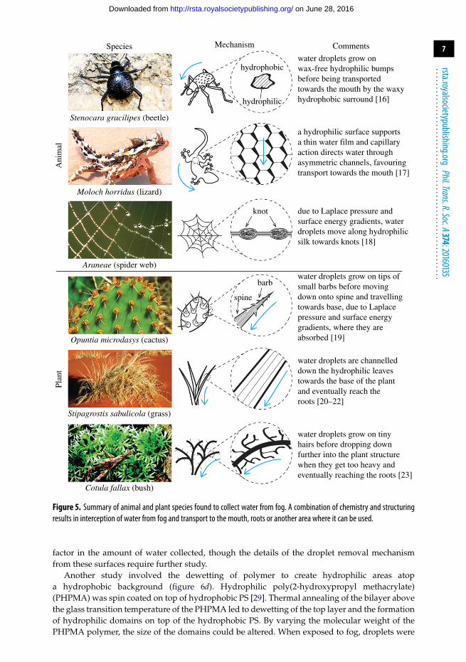
Several animal and plant species have evolved surface structures and chemistries that enablethem to collect water from fog (figure 5). These include Namib Desert beetles, several lizardspecies, spider webs and various types of cacti, grasses and other plants. These species (or, inthe case of spider webs, external structures built by a species) typically feature areas where fogdroplets can deposit and grow before eventually being transported either towards mouths, inthe case of animals, or a region that absorbs water, in the case of plants, such as the roots. In thissection of the review, we will highlight the species capable of harvesting fog and highlight severalmethods employing biomimicry and bioinspiration to aid in water collection from fog.
(a) Namib Desert beetlesStenocara gracilipes and Onymacris unguicularis are beetles native to the Namib Desert in southernAfrica. The region is one of the most arid in the world, with average annual rainfall of only 1.8 cm,and it is not uncommon to experience consecutive years with no rainfall at all [24]. However,the area is not devoid of life, with several species of flora and fauna seemingly thriving. It waspostulated that the ability to survive in this climate was the result of collection of water from fog.Despite the low rainfall, prevailing southwesterly winds form fog along the coast 60–200 days peryear, which can be blown up to 50 km inland [24]. The first observation of fog harvesting in theNamib Desert was in 1976, with beetles emerging during nocturnal fogs and lowering their headswhile oriented into the wind (figure 5) [25]. The water was found to trickle down the body of thebeetle and into the mouth. By weighing the beetle before and after fog harvesting, it was foundthat a gain of over 30% in total body weight was possible after harvesting.
In 2001, the mechanism for fog collection was uncovered [16]. It was discovered that theback of the beetle comprised a random array of 0.5 mm diameter bumps spaced 0.5–1.5 mmapart (figure 5). The bumps were found to be smooth, while the surrounding area was coveredin microstructured wax. Water from the fog is observed to land on the bumps and dropletsbegin to grow. The droplet continues to grow (up to 4–5 mm) until the weight of the dropletovercomes the capillary force and the droplet detaches and rolls down the tilted beetle’s back.It was hypothesized that the bumps are hydrophilic (water loving, see appendix A), while the
on June 28, 2016http://rsta.royalsocietypublishing.org/Downloaded from

6
rsta.royalsocietypublishing.orgPhil.Trans.R.Soc.A374:20160135
.........................................................
5 mm
(b)(a)
Figure 4. Commercial net-based water collectors currently available from (a) FogQuest (photograph by Anne Lummerich,inset: adapted with permission from [15]. Copyright 2013 American Chemical Society) and (b) Warka water (photographby Architecture and Vision).
background wax is hydrophobic (water fearing). To confirm that an array of hydrophilic bumpson a hydrophobic background is indeed responsible for the fog harvesting, the researchers createda model surface comprising 0.6 mm glass beads fixed in wax. This surface was found to collectmore water than the wax or glass surfaces taken alone [16].
Attempts to mimic the patterned back of the beetle to create fog collectors have beenundertaken (figure 6). Hydrophilic polymers have been deposited through a mask via plasmadeposition onto a superhydrophobic polymer substrate (figure 6a) [26]. Both the wettabilityof the hydrophilic spots and the pattern dimensions were investigated. It was found that, onhydrophilic spots with diameters less than 400 µm, water droplets were unable to grow to a sizesufficient for their weight to overcome the surface tension. However, this was only investigatedfor one plasma-deposited polymer; therefore, this threshold value may be different for differentwettabilities. It was found that the poly(4-vinylpyridine) spots resulted in the highest watercollection rate. However, the 4-vinylpyridine monomer used in the process to create the plasma-deposited polymer is extremely toxic and the masked plasma deposition process is not suitablefor mass production. In addition, polymers deposited onto superhydrophobic substrates maysuffer from poor interfacial adhesion. Unfortunately, no durability studies were carried out.Similarly patterned surfaces have also been created using inkjet printing [30]. In this case, thestability of the micropatterns was tested to ensure good adhesion of the hydrophilic spots to thesuperhydrophobic substrate.
Another study used hydrophilic steel needles soldered to a cooled copper block and piercedthrough a superhydrophobic film (figure 6b) [27]. Water droplets were found to condense andgrow on the tips of the cooled steel needles before rolling over the superhydrophobic film oncethey reached a certain weight (figure 7a). The study focused more on the condensation of waterfrom humid air and employed the cooling stage throughout. However, because the needle tipsare hydrophilic, it could also be used in fog collection, although the tip diameter may need to beincreased to aid attachment of the larger droplets in fog.
One fog-harvesting device that is relatively easy to fabricate consists of a wire mesh pressedinto a polymer sheet (figure 6c). Copper wire mesh was first calcined to create a copper oxidelayer featuring surface structures on the nanoscale. This, when combined with a fluorinatedthiol treatment, resulted in a superhydrophobic material. The mesh was then pressed into aheated polystyrene (PS) sheet to create a composite surface with heterogeneous wettability [28].Different mesh sizes were investigated, with the most efficient material demonstrating a watercollection rate of 160 mg cm−2 h−1. This technique is slightly different from others in that thepatterned surface features hydrophilic wells surrounded by the hydrophobic wire mesh, insteadof hydrophilic bumps surrounded by hydrophobic valleys. By varying the temperature of thesample during pressing, the depth of the wells was varied and this was found to be an important
on June 28, 2016http://rsta.royalsocietypublishing.org/Downloaded from
7
rsta.royalsocietypublishing.orgPhil.Trans.R.Soc.A374:20160135
.........................................................
water droplets grow onwax-free hydrophilic bumpsbefore being transportedtowards the mouth by the waxyhydrophobic surround [16]
a hydrophilic surface supportsa thin water film and capillaryaction directs water throughasymmetric channels, favouringtransport towards the mouth [17]
due to Laplace pressure andsurface energy gradients, waterdroplets move along hydrophilicsilk towards knots [18]
water droplets grow on tips ofsmall barbs before movingdown onto spine and travellingtowards base, due to Laplacepressure and surface energygradients, where they areabsorbed [19]
water droplets are channelleddown the hydrophilic leavestowards the base of the plantand eventually reach theroots [20–22]
water droplets grow on tinyhairs before dropping downfurther into the plant structurewhen they get too heavy andeventually reaching the roots [23]
Comments
Ani
mal
Plan
t
Mechanism
hydrophobic
hydrophilic
knot
barb
spine
Species
Stenocara gracilipes (beetle)
Moloch horridus (lizard)
Araneae (spider web)
Opuntia microdasys (cactus)
Stipagrostis sabulicola (grass)
Cotula fallax (bush)
Figure 5. Summary of animal and plant species found to collect water from fog. A combination of chemistry and structuringresults in interception of water from fog and transport to the mouth, roots or another area where it can be used.
factor in the amount of water collected, though the details of the droplet removal mechanismfrom these surfaces require further study.
Another study involved the dewetting of polymer to create hydrophilic areas atopa hydrophobic background (figure 6d). Hydrophilic poly(2-hydroxypropyl methacrylate)(PHPMA) was spin coated on top of hydrophobic PS [29]. Thermal annealing of the bilayer abovethe glass transition temperature of the PHPMA led to dewetting of the top layer and the formationof hydrophilic domains on top of the hydrophobic PS. By varying the molecular weight of thePHPMA polymer, the size of the domains could be altered. When exposed to fog, droplets were
on June 28, 2016http://rsta.royalsocietypublishing.org/Downloaded from

8
rsta.royalsocietypublishing.orgPhil.Trans.R.Soc.A374:20160135
.........................................................
polystyrene(relatively hydrophobic)
PHPMA(hydrophilic)
PE + Si-NP(superhydrophobic)
silica aerogel(insulation)
copper block(heat sink)
steel needles(hydrophilic)
CF4-treated polymer(hydrophobic)
polystyrene(relatively hydrophilic)
CuO-PFDT(superhydrophobic)
PGMA + NH2-PS(hydrophilic)
(b)(a)
(c) (d )
1 mm
Figure 6. Summary of various techniques for fabricating beetle-inspired water collectors: (a) plasma-deposited hydrophilicspots atop hydrophobic polymer (adapted with permission from [26]. Copyright 2007 American Chemical Society);(b) hydrophilic steel needles pierced through superhydrophobic film (adapted with permission from [27]. Copyright 2015American Chemical Society); (c) superhydrophobic copper mesh pressed into hydrophilic (relative to the copper mesh) polymersheet [28]; and (d) dewetted hydrophilic polymer regions atop a hydrophobic (relative to the hydrophilic polymer regions)polymer (adapted with permission from [29]. Copyright 2015 American Chemical Society).
observed to grow on the hydrophilic domains (figure 7b). However, measuring less than 10 µm insize, the hydrophilic domains are much smaller than the spots on the beetle and, depending uponthe molecular weight, are interconnected. While water droplets were found to attach and growon these hydrophilic domains, the shedding mechanism of these droplets is quite different fromthat of the beetle. It is estimated that a droplet of sufficient size to detach from the surface will bein contact with tens of thousands of hydrophilic domains. Successful droplet shedding was notdemonstrated in the paper. This step is vital as the droplets need to detach in a timely manner sonew droplets can begin to form on the vacated hydrophilic regions.
Biomimetic fog-harvesting surfaces based on the patterned surface of the beetle have alsobeen created via a patterned hydrophilic polyelectrolyte array [31] and patterned nanograss [32].However, these studies did not fully investigate the water-collecting ability of these surfaces.
(b) LizardsMoloch horridus is a species of lizard native to arid regions in western and southern Australia(figure 5). It was first believed that the lizard absorbed water through its skin. However, researchin the 1960s discovered that, instead, water droplets spread out over the skin before reaching themouth [33]. The movement of the water was attributed to capillary action along open channels inthe skin. Similarly, when water was added to the bodies of Phrynocephalus helioscopus, a species of
on June 28, 2016http://rsta.royalsocietypublishing.org/Downloaded from

9
rsta.royalsocietypublishing.orgPhil.Trans.R.Soc.A374:20160135
.........................................................
0.03 h 2.80 h
CA ~ 168 ± 2°2 mm
10 mm
100 s 150 s
1 s 20 s
needletip
waterdroplets
hydrophilicregions
hydrophobicbackground
(b)
(a)
Figure 7. Time-lapse images showing water droplet growth on beetle-inspired (a) hydrophilic steel needles pierced throughsuperhydrophobic film (adapted with permission from [27]. Copyright 2015 American Chemical Society) and (b) dewettedhydrophilic polymer regions atop a hydrophobic polymer (adapted with permission from [29]. Copyright 2015 AmericanChemical Society).
lizard native to arid regions in Asia, the lizard adopted a posture where the head was depressedand the hindquarters were elevated, which helped guide the water to the mouth [34].
A more recent study of numerous species of lizards found that several exhibit water-harvestingpotential [35]. The study of one lizard in particular, Phrynosoma cornutum or the Texas hornedlizard, found that water placed on the skin flowed preferentially towards the mouth, withcapillary forces dominating over gravitational and viscous forces (figure 8) [17]. Examinationrevealed a network of capillary channels and found that there was a narrowing of individualchannels in the direction of the mouth (longitudinal) (figure 5). An abrupt widening from onechannel to the next, in addition to an interconnecting narrower channel running laterally, wouldfollow. The narrowing of the channel results in favourable water transport in that direction dueto the curvature of the liquid–air interface. The lateral interconnecting channels overcome theeffects of the abrupt widening and help maintain an advancing liquid front [17]. In the backwarddirection, liquid flow is stopped as the channel widens and pressure would need to be applied toforce the liquid in that direction. In addition to water transport for water collectors, the authorshypothesized that channels that allow liquid flow in one direction but inhibit flow in the otherdirection could find use in microfluidic and medical applications. However, no artificial surfacesbased on the structure of the lizard for water collection have yet been created.
(c) Spider websSpider silk has been well studied as a fibre with excellent mechanical characteristics. This naturalmaterial comprises proteins and outperforms many synthetic materials with regards to strengthand elasticity [36]. Spider webs are also known to collect water, as evidenced by the manyphotographs capturing a dew-glistened web (figure 5). Dry webs undergo moisture-induced
on June 28, 2016http://rsta.royalsocietypublishing.org/Downloaded from
10
rsta.royalsocietypublishing.orgPhil.Trans.R.Soc.A374:20160135
.........................................................
snout +26%
0 s
3.3 s 5.0 s
1.6 s
+70%+48%
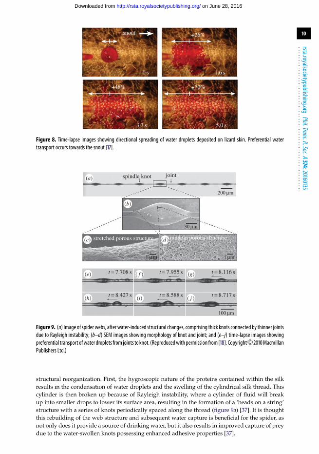
Figure 8. Time-lapse images showing directional spreading of water droplets deposited on lizard skin. Preferential watertransport occurs towards the snout [17].
spindle knot
stretched porous structure random porous structure
joint
200 mm
30 mm
1 mm
t = 7.708 s t = 7.955 s t = 8.116 s
t = 8.427 s t = 8.588 s t = 8.717 s
1 mm
100 mm
(b)
(a)
(g)
(d )(c)
(e)
(h) (i) ( j )
( f )
Figure 9. (a) Image of spider webs, after water-induced structural changes, comprising thick knots connected by thinner jointsdue to Rayleigh instability; (b–d) SEM images showing morphology of knot and joint; and (e–j) time-lapse images showingpreferential transport ofwater droplets from joints to knot. (Reproducedwithpermission from [18]. Copyright 2010MacmillanPublishers Ltd.)
structural reorganization. First, the hygroscopic nature of the proteins contained within the silkresults in the condensation of water droplets and the swelling of the cylindrical silk thread. Thiscylinder is then broken up because of Rayleigh instability, where a cylinder of fluid will breakup into smaller drops to lower its surface area, resulting in the formation of a ‘beads on a string’structure with a series of knots periodically spaced along the thread (figure 9a) [37]. It is thoughtthis rebuilding of the web structure and subsequent water capture is beneficial for the spider, asnot only does it provide a source of drinking water, but it also results in improved capture of preydue to the water-swollen knots possessing enhanced adhesive properties [37].
on June 28, 2016http://rsta.royalsocietypublishing.org/Downloaded from

11
rsta.royalsocietypublishing.orgPhil.Trans.R.Soc.A374:20160135
.........................................................
Analysis of the wet-rebuilt web using scanning electron microscopy (SEM) revealed that theknots were composed of randomly oriented porous nanofibrils, while the interconnecting jointswere composed of stretched porous nanofibrils aligned parallel to the thread (figure 9b–d) [18].When water condensed on the wet-rebuilt spider thread, the droplets condensing on the jointswere found to move to the knots (figure 9e–j). This is thought to be because of a combination ofa surface tension gradient due to the knots displaying a rougher surface thanks to the randomlyoriented nanofibrils (the roughness enhances their hydrophilicity as the droplets are in the Wenzelstate of wetting, see appendix A), and a Laplace pressure gradient due to the higher radius ofcurvature of the joints compared with the larger knots [18].
For a droplet resting on such a fibre, the changing fibre radius (r) results in a pressure differenceinside the droplet. At low fibre radius, the droplet shape (where h is the height of the droplet) ishardly deformed by the fibre (as r < h) and is near spherical (�P = 2γ /h, where γ is the surfacetension). As the fibre radius is increased, h tends towards r and the droplet becomes flatter (�P =γ /r). This flattening results in a lower Laplace pressure and droplets therefore move on a conicalfibre from regions of low radius to regions of higher radius [38].
The combination of this Laplace pressure gradient and the surface tension gradient resultsin the transport of droplets towards the knots (figure 5). Even micrometre-sized droplets wereobserved to move, despite the increased importance of contact angle hysteresis effects at thisscale (see appendix) [18].
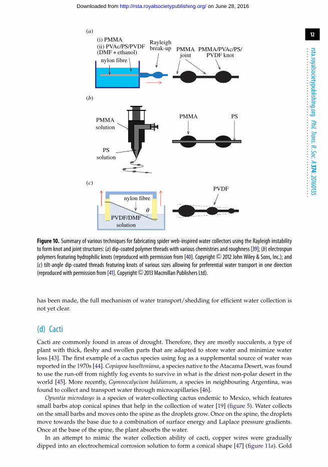
Many of the attempts to replicate the spider web use the same Rayleigh instabilities thatdictate its structure. For instance, nylon fibres immersed in a poly(methyl methacrylate) (PMMA)solution [39] were removed to leave a thin, cylindrical film of the polymer solution on the fibre.This then spontaneously broke up into regularly spaced knots because of the Rayleigh instability(figure 10a). The fibres were then treated with a second polymer solution to alter the chemistryand roughness of the knots. By altering the polymer and solvents used, the knots could befunctionalized with a variety of surface energies and levels of roughness, respectively, with thejoints remaining unchanged. It was found that when smooth hydrophobic knots were created,droplets could be driven from the knots onto the hydrophilic interconnecting joints, which isthe opposite direction to that found on the spider web. This was due to the surface energygradient being able to overcome the Laplace pressure force gradient. When the hydrophobicknots were rough, the droplets would travel towards the knots as hysteresis resistance preventsthe droplet from following the surface energy gradient and instead the Laplace pressure forcegradient dictates the movement of the drops [39]. The same group also investigated the effect ofpolymer concentration and the velocity of removing the nylon thread from solution, which wereboth found to alter the size of the knots [42]. Threads with larger knots were found to displayincreased water collection abilities.
Bioinspired fibres have also been created via coaxial electrospinning (figure 10b). PS andPMMA solutions were electrospun together forming a fibre with a PS inner and a PMMA outershell [40]. The dilute nature of the PMMA solution means the Rayleigh instability is able toovercome the viscous forces and this results in a thread composed primarily of PS with knotsof PMMA evenly distributed along its length. Water collection experiments found that dropletstravelled towards the knots because of a combination of the surface energy gradient and Laplacepressure gradient.
While the knots on spider webs can help to coalesce and grow water droplets on the thread,there is no transport of the droplets over larger distances. It was found that dipping andwithdrawing a thread in a polymer solution at a fixed angle could vary the size of the knotsformed across the thread (figure 10c) [41]. It was found that the thread was able to transporta droplet in the direction of increasing knot size, which the authors attribute to a continuouschange in the Laplace pressure and droplet coalescence. Despite the promise of improved watertransport, the use of bioinspired threads for water collection still faces challenges. Many studiesfocus on the water collection properties of a single thread and do not attempt to create a largerdevice. Additionally, the thin threads being studied may not be durable enough to withstand theextreme environments where fog collection would be beneficial. Finally, although some progress
on June 28, 2016http://rsta.royalsocietypublishing.org/Downloaded from
12
rsta.royalsocietypublishing.orgPhil.Trans.R.Soc.A374:20160135
.........................................................
(a)
(b)
(c)
nylon fibre
qPVDF/DMF
solution
PVDF
PMMAsolution
PSsolution
PMMA PS
(i) PMMA(ii) PVAc/PS/PVDF(DMF + ethanol)
nylon fibre
Rayleighbreak-up PMMA
jointPMMA/PVAc/PS/
PVDF knot
Figure 10. Summary of various techniques for fabricating spider web-inspired water collectors using the Rayleigh instabilityto form knot and joint structures: (a) dip-coated polymer threads with various chemistries and roughness [39]; (b) electrospunpolymers featuring hydrophilic knots (reproduced with permission from [40]. Copyright 2012 John Wiley & Sons, Inc.); and(c) tilt-angle dip-coated threads featuring knots of various sizes allowing for preferential water transport in one direction(reproduced with permission from [41]. Copyright 2013 Macmillan Publishers Ltd).
has been made, the full mechanism of water transport/shedding for efficient water collection isnot yet clear.
(d) CactiCacti are commonly found in areas of drought. Therefore, they are mostly succulents, a type ofplant with thick, fleshy and swollen parts that are adapted to store water and minimize waterloss [43]. The first example of a cactus species using fog as a supplemental source of water wasreported in the 1970s [44]. Copiapoa haseltoniana, a species native to the Atacama Desert, was foundto use the run-off from nightly fog events to survive in what is the driest non-polar desert in theworld [45]. More recently, Gymnocalycium baldianum, a species in neighbouring Argentina, wasfound to collect and transport water through microcapillaries [46].
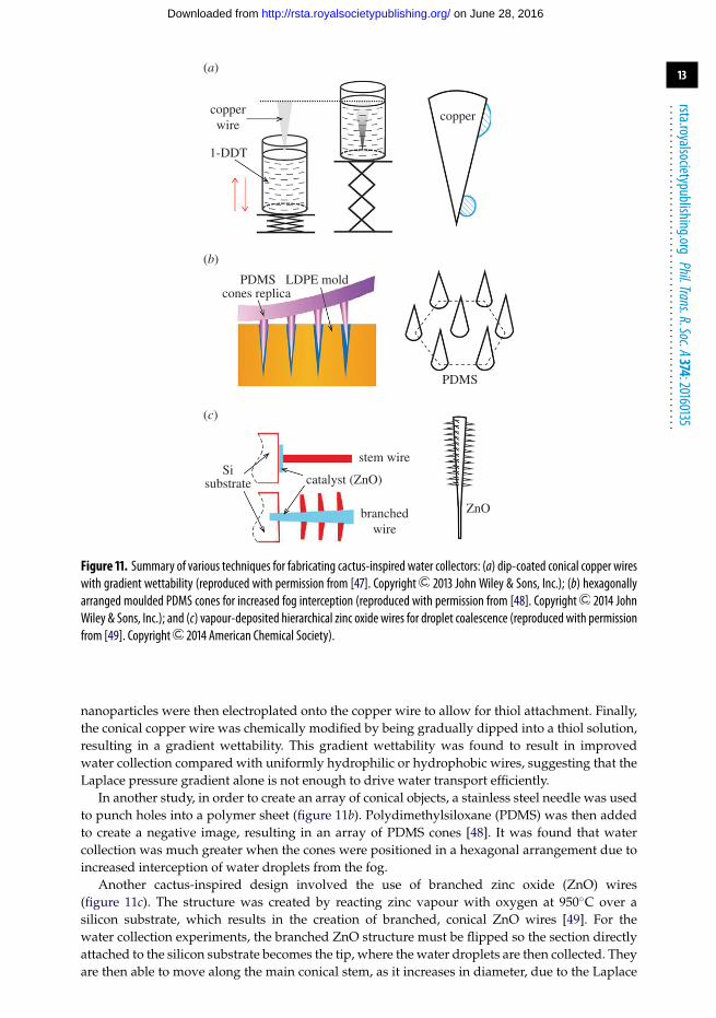
Opuntia microdasys is a species of water-collecting cactus endemic to Mexico, which featuressmall barbs atop conical spines that help in the collection of water [19] (figure 5). Water collectson the small barbs and moves onto the spine as the droplets grow. Once on the spine, the dropletsmove towards the base due to a combination of surface energy and Laplace pressure gradients.Once at the base of the spine, the plant absorbs the water.
In an attempt to mimic the water collection ability of cacti, copper wires were graduallydipped into an electrochemical corrosion solution to form a conical shape [47] (figure 11a). Gold
on June 28, 2016http://rsta.royalsocietypublishing.org/Downloaded from
13
rsta.royalsocietypublishing.orgPhil.Trans.R.Soc.A374:20160135
.........................................................
copperwire
copper
Sisubstrate
stem wire
catalyst (ZnO)
ZnObranchedwire
PDMS
PDMS
LDPE moldcones replica
1-DDT
(b)
(a)
(c)
Figure 11. Summary of various techniques for fabricating cactus-inspired water collectors: (a) dip-coated conical copper wireswith gradient wettability (reproduced with permission from [47]. Copyright 2013 John Wiley & Sons, Inc.); (b) hexagonallyarranged moulded PDMS cones for increased fog interception (reproduced with permission from [48]. Copyright 2014 JohnWiley & Sons, Inc.); and (c) vapour-deposited hierarchical zinc oxide wires for droplet coalescence (reproduced with permissionfrom [49]. Copyright 2014 American Chemical Society).
nanoparticles were then electroplated onto the copper wire to allow for thiol attachment. Finally,the conical copper wire was chemically modified by being gradually dipped into a thiol solution,resulting in a gradient wettability. This gradient wettability was found to result in improvedwater collection compared with uniformly hydrophilic or hydrophobic wires, suggesting that theLaplace pressure gradient alone is not enough to drive water transport efficiently.
In another study, in order to create an array of conical objects, a stainless steel needle was usedto punch holes into a polymer sheet (figure 11b). Polydimethylsiloxane (PDMS) was then addedto create a negative image, resulting in an array of PDMS cones [48]. It was found that watercollection was much greater when the cones were positioned in a hexagonal arrangement due toincreased interception of water droplets from the fog.
Another cactus-inspired design involved the use of branched zinc oxide (ZnO) wires(figure 11c). The structure was created by reacting zinc vapour with oxygen at 950◦C over asilicon substrate, which results in the creation of branched, conical ZnO wires [49]. For thewater collection experiments, the branched ZnO structure must be flipped so the section directlyattached to the silicon substrate becomes the tip, where the water droplets are then collected. Theyare then able to move along the main conical stem, as it increases in diameter, due to the Laplace
on June 28, 2016http://rsta.royalsocietypublishing.org/Downloaded from
14
rsta.royalsocietypublishing.orgPhil.Trans.R.Soc.A374:20160135
.........................................................
pressure gradient. The branched structure formed near the base of the main stem was foundto collect additional water, which penetrated into the gaps between the branches and coalescedwith the droplets travelling from the tip. The water collected at the base of the stem was thenremoved by syringe. Although these experiments demonstrated the water collection ability ofthese structures, they would seem to be unfeasible for fabrication of a viable water collectiondevice. The ZnO structures would need to be manually removed, flipped and re-attached to thesubstrate. Additionally, the durability of these delicate structures has not been studied. It is alsonot clear if the water can be removed from the base of the main stem without the use of externalpressure.
(e) Other plant speciesOther plant species adapted to collect water from fog include Stipagrostis sabulicola, a grassendemic to the Namib Desert. First studied in 1980, water droplets are observed to collect onthe leaf before coalescing and running down towards the base of the plant [20,50]. The leavesfeature longitudinal ridges, which dictate this fluid flow (figure 5) [21]. Another type of grass,Setaria viridis, is found to collect water with a similar structure and mechanism to that found onthe Opuntia microdasys cactus [51].
Another plant studied for water collection from fog is Cotula fallax, which is native to SouthAfrica. Fine hairs on the leaves of the plant intercept fog droplets where they coalesce and growbefore dropping down through the plant structure when they become too heavy (figure 5) [23].This fog-harvesting mechanism allows efficient collection of water from multiple directions,unlike other two-dimensional structures such as those based on the beetle back.
(f) OutlookOf all the bioinspired fog harvesters reviewed here, using patterned heterogeneous surfacesbased on the beetle back is perhaps the most common method. However, challenges here stillremain. Although several papers have demonstrated that hydrophilic spots deposited on top ofhydrophobic or even superhydrophobic backgrounds are able to collect water from fog, the long-term durability of these materials has not been fully investigated. For instance, the depositionof such islands upon low-surface-energy films may result in poor interfacial adhesion, andtherefore low mechanical durability. The issue of durability is particularly important given thatfog harvesters will be required in remote regions where regular maintenance is not possible,or areas prone to extreme conditions such as high diurnal temperature variation and abrasionfrom sand.
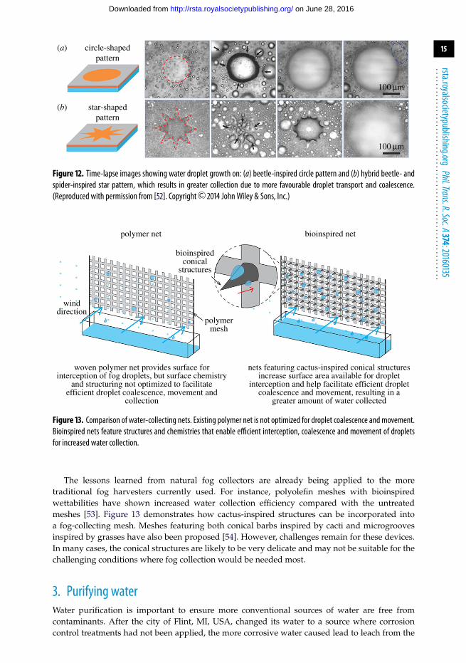
The lessons learned from different natural surfaces can also be combined to enhancewater collection on bioinspired surfaces. For instance, a patterned heterogeneous surface withhydrophilic spots on a hydrophobic background—as inspired by the beetle back—can bemodified to include hydrophilic star shapes in place of circular sports, as inspired by spiderwebs (figure 12). Bai et al. [52] found that surfaces featuring stars were more efficient at collectingwater than those with circular spots. The authors attributed this to the Laplace pressure gradientresulting in a droplet being transported more efficiently from one of the tips of the star into thecentre, leaving the area clear for collection of new droplets [52].
In terms of fabricating a water collection device, cactus-inspired structures are favourableas they can use surface energy and Laplace pressure gradients to drive droplets in a specificdirection. This contrasts with most designs inspired by spider webs in which droplet transportis to the nearest knot where it must remain until it grows sufficiently in size to detach. Cactus-inspired designs also have advantages over those based on the beetle back as three-dimensionalstructures can be created to increase the surface area, which gives rise to increased dropletinterception.
on June 28, 2016http://rsta.royalsocietypublishing.org/Downloaded from
15
rsta.royalsocietypublishing.orgPhil.Trans.R.Soc.A374:20160135
.........................................................
circle-shapedpattern
star-shapedpattern
100 mm
100 mm
(b)
(a)
Figure 12. Time-lapse images showing water droplet growth on: (a) beetle-inspired circle pattern and (b) hybrid beetle- andspider-inspired star pattern, which results in greater collection due to more favourable droplet transport and coalescence.(Reproduced with permission from [52]. Copyright 2014 John Wiley & Sons, Inc.)
nets featuring cactus-inspired conical structuresincrease surface area available for droplet
interception and help facilitate efficient dropletcoalescence and movement, resulting in a
greater amount of water collected
woven polymer net provides surface forinterception of fog droplets, but surface chemistry
and structuring not optimized to facilitateefficient droplet coalescence, movement and
collection
polymermesh
winddirection
bioinspiredconical
structures
polymer net bioinspired net
Figure 13. Comparison of water-collecting nets. Existing polymer net is not optimized for droplet coalescence and movement.Bioinspired nets feature structures and chemistries that enable efficient interception, coalescence and movement of dropletsfor increased water collection.
The lessons learned from natural fog collectors are already being applied to the moretraditional fog harvesters currently used. For instance, polyolefin meshes with bioinspiredwettabilities have shown increased water collection efficiency compared with the untreatedmeshes [53]. Figure 13 demonstrates how cactus-inspired structures can be incorporated intoa fog-collecting mesh. Meshes featuring both conical barbs inspired by cacti and microgroovesinspired by grasses have also been proposed [54]. However, challenges remain for these devices.In many cases, the conical structures are likely to be very delicate and may not be suitable for thechallenging conditions where fog collection would be needed most.
3. Purifying waterWater purification is important to ensure more conventional sources of water are free fromcontaminants. After the city of Flint, MI, USA, changed its water to a source where corrosioncontrol treatments had not been applied, the more corrosive water caused lead to leach from the
on June 28, 2016http://rsta.royalsocietypublishing.org/Downloaded from

16
rsta.royalsocietypublishing.orgPhil.Trans.R.Soc.A374:20160135
.........................................................
osmosis reverse osmosis
osmoticpressure
Na+
H2O
H2O
semipermeablemembrane
water moves through semi-permeable membrane into region
with higher salt concentration in anattempt to equalize solute
concentrations on both sides
external pressure is applied toovercome osmotic pressure,
causing water to move throughsemipermeable membrane to
region with lower salt concentration
semipermeablemembrane
externalpressure
Cl–
Figure 14. Schematic showing the differences between osmosis and reverse osmosis. In osmosis, water travels across asemipermeable membrane to equalize solute concentrations. In reverse osmosis, external pressure is applied to prevent watertravelling into regions of higher solute concentration and additional pressure instead causeswater to travel into regions of lowersolute concentrations.
ageing pipe network, culminating in a serious threat to public health [55]. The change has alsobeen linked to an outbreak of Legionnaires’ disease, a type of pneumonia caused by bacteria [56].Proper water purification could prevent such contaminants from reaching human consumers.
When it comes to purifying water, there are numerous techniques available, including the useof adsorbents such as activated carbon [57], biomaterials [58] and zeolites (porous minerals) [59]to remove organics from wastewater. However, the use of adsorbents has its downsides, such asinefficiencies due to contaminant removal and regeneration of the adsorbent.
Ultraviolet treatments have also been used to disinfect water [60], and can be combined withmetal oxide catalysts for improved oxidation rates. However, the use of ultraviolet light cannotremove heavy-metal or other non-living contaminants, and the process can be expensive andineffective on cloudy or turbid water.
Conventional purification techniques typically involve membranes and the separation ofcontaminants. There are two mechanisms that dictate water transport through a membrane,both of which can occur together. One mechanism is solution–diffusion, where water moleculesdissolve into the membrane and diffuse through the membrane to desorb from the other side.Another mechanism is pore flow, where the size of the pores is smaller than the contaminantbeing removed [61]. Membranes are typically polymeric in nature, but there are examples ofceramic membranes composed of materials such as alumina, titania and silicon carbide, for high-temperature applications. Nanomembranes made of graphene [62] or etched silicon [63] are alsobeing developed.
One potential source of water is the oceans, which account for 96.5% of all water on theplanet [2]. However, in terms of human consumption, ocean water is contaminated by salts, aswell as by bacteria and particulates. To make ocean water fit for human consumption, it must firstbe desalinated and purified [10].
For desalination, a common technique is reverse osmosis. Normally, if two aqueous solutionswith varying solute concentrations are placed either side of a semipermeable membrane, waterwill move through the membrane from a region of low solute concentration to a regionof higher solute concentration in an attempt to equalize the concentrations (figure 14). Thisprocess is known as osmosis and the tendency for a solution to take in water is defined asthe osmotic pressure. In reverse osmosis (RO), external pressure is applied to overcome thisosmotic pressure, preventing the flow of water into the region of higher solute concentration.
on June 28, 2016http://rsta.royalsocietypublishing.org/Downloaded from

17
rsta.royalsocietypublishing.orgPhil.Trans.R.Soc.A374:20160135
.........................................................
microporous
water colloidal solids
oil emulsions
bacteria
bacterialthreads
eggshell
viruses
proteins
ions
aquaporins surfacelayer
proteinscarbon nanotubes
block copolymers
templated metal oxides
pore-forming
molecules
0.1 nm
targetsolute
naturalporous
material
bioinspiredporous
material
1 nm 10 nm 100 nm 1 mm 10 mm
0.1 nm 1 nm 10 nm 100 nm 1 mm 10 mm
mesoporous macroporous
Figure 15. Comparison of length scales of target solutes, natural porous materials and bioinspired porous materials.
Additional pressure above the osmotic pressure will instead cause water to move into theregion of lower solute concentration (figure 14). The requirement for this applied pressuremeans that separation via an RO membrane can be energy-intensive, consuming at least2 kWh m−3 [10], whereas the theoretical minimum energy required for desalination should bearound 1 kWh m−3 [11]. This excess pressure is due to the low permeability of the membranesinvolved. A membrane with low water permeability will require additional applied pressureabove that required to balance the osmotic pressure in order to result in reasonable waterfluxes [11]. Therefore, biomimicry is an appealing alternative, as nature has examples ofmembranes with higher separation rates and permeabilities than man-made equivalents. In thissection of the review, we will focus on methods that employ biomimicry and bioinspiration to aidin water purification.
The focus of many studies of bioinspired membranes is typically porous materials fornanofiltration and RO applications. Porous materials are classified into three main categoriesdepending upon their pore size. For instance, microporous materials contain pore diameters lessthan 2 nm, which are required for desalination. However, ocean water (and other water sources)can contain many contaminants other than salts that make it unsuitable for various applications,including drinking water. Such contaminants are typically many orders of magnitude largerthan the inorganic ions found in salts. When salt removal is not required, membranes withlarger pores would probably be sufficient for these applications. In addition to separationapplications, ordered macroporous (pore diameters 2–50 nm) or mesoporous (pore diametersgreater than 50 nm) materials could also find use in ion exchange [64], catalysis [65] and batterytechnology [66]. A summary of the various pore sizes, including solutes that can be targeted inthis size range, examples in nature and their bioinspired equivalents is provided in figure 15and table 1.
(a) Multicellular structuresA common method for the creation of biomimetic microporous membranes is through the useof templating techniques. One early example is the use of bacterial threads to form ordered
on June 28, 2016http://rsta.royalsocietypublishing.org/Downloaded from

18
rsta.royalsocietypublishing.orgPhil.Trans.R.Soc.A374:20160135
.........................................................
Table 1. Examples of target solute, natural materials and bioinspired equivalents sorted by membrane pore size.
natural porous bioinspired porous
pore size target solute material material
macropores (>50 nm) bacteria (0.2–750µm) eggshell, bacterialthreads
carbon nanotubes, templated silica
. . . . . . . . . . . . . . . . . . . . . . . . . . . . . . . . . . . . . . . . . . . . . . . . . . . . . . . . . . . . . . . . . . . . . . . . . . . . . . . . . . . . . . . . . . . . . . . . . . . . . . . . . . . . . . . . . . . . . . . . . . . . . . . . . . . . . . . . . . . . . . . . . . . . . . . . . . . . . . .
oil emulsions (0.1–10µm). . . . . . . . . . . . . . . . . . . . . . . . . . . . . . . . . . . . . . . . . . . . . . . . . . . . . . . . . . . . . . . . . . . . . . . . . . . . . . . . . . . . . . . . . . . . . . . . . . . . . . . . . . . . . . . . . . . . . . . . . . . . . . . . . . . . . . . . . . . . . . . . . . . . . . . . . . . . . . . . . . . . . . . . . . . . . . . . . . . . . . . . . . . . . . . . . . . . . . . . . .
mesopores (2–50 nm) colloidal solids(0.01–1µm)
surface layer proteins carbon nanotubes, self-assembledblock copolymers
. . . . . . . . . . . . . . . . . . . . . . . . . . . . . . . . . . . . . . . . . . . . . . . . . . . . . . . . . . . . . . . . . . . . . . . . . . . . . . . . . . . . . . . . . . . . . . . . . . . . . . . . . . . . . . . . . . . . . . . . . . . . . . . . . . . . . . . . . . . . . . . . . . . . . . . . . . . . . . .
viruses (20–400 nm). . . . . . . . . . . . . . . . . . . . . . . . . . . . . . . . . . . . . . . . . . . . . . . . . . . . . . . . . . . . . . . . . . . . . . . . . . . . . . . . . . . . . . . . . . . . . . . . . . . . . . . . . . . . . . . . . . . . . . . . . . . . . . . . . . . . . . . . . . . . . . . . . . . . . . . . . . . . . . .
proteins (2–10 nm). . . . . . . . . . . . . . . . . . . . . . . . . . . . . . . . . . . . . . . . . . . . . . . . . . . . . . . . . . . . . . . . . . . . . . . . . . . . . . . . . . . . . . . . . . . . . . . . . . . . . . . . . . . . . . . . . . . . . . . . . . . . . . . . . . . . . . . . . . . . . . . . . . . . . . . . . . . . . . . . . . . . . . . . . . . . . . . . . . . . . . . . . . . . . . . . . . . . . . . . . .
micropores (0.2–2 nm) inorganic ions(0.2–0.4 nm)
aquaporins carbon nanotubes, amphiphilicdipeptides, cyclic peptides,crown ethers
. . . . . . . . . . . . . . . . . . . . . . . . . . . . . . . . . . . . . . . . . . . . . . . . . . . . . . . . . . . . . . . . . . . . . . . . . . . . . . . . . . . . . . . . . . . . . . . . . . . . . . . . . . . . . . . . . . . . . . . . . . . . . . . . . . . . . . . . . . . . . . . . . . . . . . . . . . . . . . .
water (0.2 nm). . . . . . . . . . . . . . . . . . . . . . . . . . . . . . . . . . . . . . . . . . . . . . . . . . . . . . . . . . . . . . . . . . . . . . . . . . . . . . . . . . . . . . . . . . . . . . . . . . . . . . . . . . . . . . . . . . . . . . . . . . . . . . . . . . . . . . . . . . . . . . . . . . . . . . . . . . . . . . . . . . . . . . . . . . . . . . . . . . . . . . . . . . . . . . . . . . . . . . . . . .
silica macrostructures. This was achieved by first slowly extracting a thread from a culture ofBacillus subtilis, which caused the multicellular filaments to become aligned into a collectionof hexagonally close-packed cylinders [67]. The thread is then dipped into an aqueous solcomprising colloidal silica nanoparticles. As the thread is dried, the nanoparticles coat the thread,after which the organic material is then removed via heating to result in pore widths of 0.5 µm.Other examples of templating membranes are shown in figure 16.
Template mineralization has been performed using the internal shell of Sepia officinalis orcuttlefish (figure 16a) [68]. This cuttlebone consists of a highly organized structure comprisingcalcium carbonate on a chitin framework. By removing the calcium carbonate from theframework, the chitin can be remineralized using an aqueous sodium silicate solution. The chitintemplate can then be removed by calcining. A similar technique used potato starch gels as thetemplate to create silicalite nanoparticle thin films with hierarchical porosity (figure 16b) [69]. Itwas found that the pore size could be varied from 0.5 to 50 µm by altering the amount of starchin the suspension.
Another method for creating template metal oxide membranes involved the use of eggshells(figure 16c) [70]. Eggshells contain membranes with a macroporous network of interwoven fibreswith typical pore sizes of 5 µm. The membrane surface consists of amines and carboxylic acidgroups capable of interacting with titania precursors. The eggshell was first dipped in a tetra-n-butyl titanium solution before being transferred to a propanol/water mixture, resulting in thehydrolysis and condensation of titania onto the surfaces of the eggshell membrane. After removalof the organic material through heating, a titania porous network remained. While the authorstheorized the material would have promising catalytic and photovoltaic properties, no studies ofthe potential for these materials in separation techniques were carried out.
For smaller pore sizes, wood cellular structures have been combined with surfactant to createhierarchically ordered porous material (figure 16d) [71,72]. The wood was soaked in a solutioncontaining surfactant and silicate. The silicate penetrated the cell walls and was hydrolysedand condensed onto the internal structures of the wood. The surfactant was added and becameincorporated into the silica network, forming nanoporous channels necessary for the evacuationof the organic matter during calcination. It was found that using different tree samples as thetemplate resulted in different pore diameter, volume and surface area. Pore sizes of 2.5–3 nmwere achieved. Despite several examples of biological materials being used as templates to create
on June 28, 2016http://rsta.royalsocietypublishing.org/Downloaded from

19
rsta.royalsocietypublishing.orgPhil.Trans.R.Soc.A374:20160135
.........................................................
250 mm
5 mm
50 mm
50 mm
(b)(a)
(c) (d )
Figure 16. Summary of various techniques for fabricating multicellular-inspired membranes: (a) cuttlebone-templatedsilica featuring a highly organized internal structure (reproduced with permission from [68]. Copyright 2000 AmericanChemical Society); (b) starch-templated silicalite where pore size is varied by altering the amount of starch (reproduced withpermission from [69]. Copyright 2002 American Chemical Society); (c) eggshell-templated titania featuring interwovenfibres and typical pore sizes of 5µm (reproduced with permission from [70]. Copyright 2002 John Wiley & Sons, Inc); and(d) wood cellular-templated silica where changing the species of wood can alter the pore structure (reproduced withpermission from [71]. Copyright 2001 John Wiley & Sons, Inc.).
porous metal oxide films, these studies typically do not investigate the use of these materials inthe purification of water.
(b) Surface layer proteinsA collection of crystalline protein subunits called surface layers (S-layers) is a common structurefound on the surface of single-celled organisms. These S-layers contain pores typically 2–8 nmin diameter. The specific size of the pores varies depending upon the species of organism theyreside upon. However, pore size is extremely uniform for a given S-layer, as it is determined bythe assembly of identical protein subunits [73].
S-layer-based membranes were prepared by suspending S-layer fragments in water and thendepositing them on a polymer support membrane with pore sizes of 0.1 µm [74]. The presence ofan intact S-layer membrane film covering the pores of the membrane support was confirmedby size exclusion experiments, which displayed 100% rejection of the ferritin protein (12 nmdiameter). The existence of functional groups at well-defined positions and orientations withinthe pores means that it is very straightforward to apply chemical modifications to the S-layermembranes for improved selectivity and anti-fouling [75].
The creation and study of membranes comprising S-layer proteins is uncommon because ofinstability and issues with scale-up. However, the technique of using the self-assembly of identicalsubunits to form uniform-sized pores has been exploited when mimicking another pore-formingprotein, aquaporins.
on June 28, 2016http://rsta.royalsocietypublishing.org/Downloaded from
20
rsta.royalsocietypublishing.orgPhil.Trans.R.Soc.A374:20160135
.........................................................
conserved
NPA motif
extracellulara
cc e
b d
M5
M8
M1
M2M7
M6
M3
C terminus
N terminus
cytoplasmic
M4
N194
P195
A196 pore
R197 F58
H182
ar/Rresidues
I192, C191,G190, G189
(a) (b)
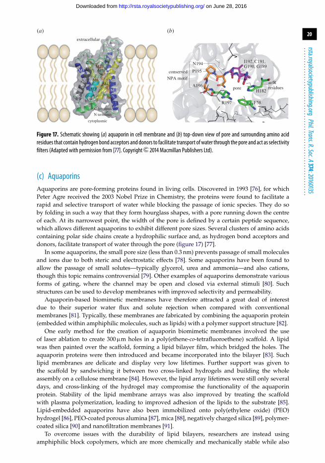
Figure 17. Schematic showing (a) aquaporin in cell membrane and (b) top-down view of pore and surrounding amino acidresidues that contain hydrogen bond acceptors and donors to facilitate transport ofwater through the pore and act as selectivityfilters (Adapted with permission from [77]. Copyright 2014 Macmillan Publishers Ltd).
(c) AquaporinsAquaporins are pore-forming proteins found in living cells. Discovered in 1993 [76], for whichPeter Agre received the 2003 Nobel Prize in Chemistry, the proteins were found to facilitate arapid and selective transport of water while blocking the passage of ionic species. They do soby folding in such a way that they form hourglass shapes, with a pore running down the centreof each. At its narrowest point, the width of the pore is defined by a certain peptide sequence,which allows different aquaporins to exhibit different pore sizes. Several clusters of amino acidscontaining polar side chains create a hydrophilic surface and, as hydrogen bond acceptors anddonors, facilitate transport of water through the pore (figure 17) [77].
In some aquaporins, the small pore size (less than 0.3 nm) prevents passage of small moleculesand ions due to both steric and electrostatic effects [78]. Some aquaporins have been found toallow the passage of small solutes—typically glycerol, urea and ammonia—and also cations,though this topic remains controversial [79]. Other examples of aquaporins demonstrate variousforms of gating, where the channel may be open and closed via external stimuli [80]. Suchstructures can be used to develop membranes with improved selectivity and permeability.
Aquaporin-based biomimetic membranes have therefore attracted a great deal of interestdue to their superior water flux and solute rejection when compared with conventionalmembranes [81]. Typically, these membranes are fabricated by combining the aquaporin protein(embedded within amphiphilic molecules, such as lipids) with a polymer support structure [82].
One early method for the creation of aquaporin biomimetic membranes involved the useof laser ablation to create 300 µm holes in a poly(ethene-co-tetrafluoroethene) scaffold. A lipidwas then painted over the scaffold, forming a lipid bilayer film, which bridged the holes. Theaquaporin proteins were then introduced and became incorporated into the bilayer [83]. Suchlipid membranes are delicate and display very low lifetimes. Further support was given tothe scaffold by sandwiching it between two cross-linked hydrogels and building the wholeassembly on a cellulose membrane [84]. However, the lipid array lifetimes were still only severaldays, and cross-linking of the hydrogel may compromise the functionality of the aquaporinprotein. Stability of the lipid membrane arrays was also improved by treating the scaffoldwith plasma polymerization, leading to improved adhesion of the lipids to the substrate [85].Lipid-embedded aquaporins have also been immobilized onto poly(ethylene oxide) (PEO)hydrogel [86], PEO-coated porous alumina [87], mica [88], negatively charged silica [89], polymer-coated silica [90] and nanofiltration membranes [91].
To overcome issues with the durability of lipid bilayers, researchers are instead usingamphiphilic block copolymers, which are more chemically and mechanically stable while also
on June 28, 2016http://rsta.royalsocietypublishing.org/Downloaded from

21
rsta.royalsocietypublishing.orgPhil.Trans.R.Soc.A374:20160135
.........................................................
(a) (b)
pore containsamino acidside groups
(c)
top-down view
(d)OH
OH
R
RR
R
OH
OH
OH
OH
OH
HO
HO
HO
HO
HN
HO
O
O
O
OO
R
R
R
R
R
R
R
R
R
nN HO
Figure 18. Summary of various techniques for fabricating aquaporin-inspired membranes: (a) cyclic peptides containing apore with a 0.7 nm internal diameter (adapted with permission from [93]. Copyright 1993 Macmillan Publishers Ltd);(b) dendritic peptides featuring hydrophobic side groups within the pore for fast transport of water (adapted with permissionfrom [94]. Copyright 2007 American Chemical Society); (c) crown ethers where the size of the ring n can be altered; and(d) cyclic arenes, which form hexamers that go on to form a channel with pores 1.8 nm in diameter.
allowing the incorporation of the aquaporin protein. One example of a polymeric membranecontaining the aquaporin protein was found to exhibit water permeabilities an order ofmagnitude higher than conventional polymer membranes [92]. A remaining challenge is theproduction of the aquaporins themselves. While aquaporins have been successfully producedin a laboratory setting, it is typically in small quantities for characterization purposes, thoughrecent work suggests large-scale aquaporin production may yet be realized [61].
(i) Pore-forming molecules
In place of aquaporins, researchers have instead turned to other molecules that can mimicthe pore-forming nature of the proteins (figure 18). One example is the use of cyclic peptides(figure 18a) [93]. The ring-shaped peptide consists of eight amino acids with alternating chirality(D or L) such that all the amide functionalities lie perpendicular to the plane of the ring. Thisallows for intermolecular hydrogen bonding between rings, resulting in a tubular structure thatwas found to reach up to hundreds of nanometres in length. The alternating chirality also ensuresthat the amino acid side groups (R groups) all lie on the outside of the ring structure to result intubes with an internal diameter of 0.7–0.8 nm. The authors suggested such structures could finduse in catalysis, electronics or separations; more recent studies have involved creating designsmore compatible with polymeric membrane processing [95].
Another example involves the use of dendritic (branched) dipeptides that can self-assemble,either in solution or when cast in a film, into helical pores (figure 18b) [96]. Unlike the cyclic
on June 28, 2016http://rsta.royalsocietypublishing.org/Downloaded from

22
rsta.royalsocietypublishing.orgPhil.Trans.R.Soc.A374:20160135
.........................................................
peptides mentioned above, the pores formed from the dendritic dipeptides contain amino acidside groups on their interior. This was found to result in a hydrophobic channel, which isfavourable for fast transport of water with high selectivity. It is also possible to alter the porestructure by replacing sequences in the dipeptides. For instance, pore sizes can be varied from0.2 to 2.4 nm by altering the peptide apex or branches. Proton transport measurements concludedthat these pores are functional.
Crown ethers are cyclic compounds consisting of multiple ether groups. In another example ofpore-forming molecules, crown ethers were functionalized with ureido groups (figure 18c) [97].This molecule can self-organize into tubes via hydrogen bonding of these groups. By changing thenumber of ether groups within the ring (n), the pore size can be altered. These molecular channelswere found to self-assemble within an existing lipid membrane, though conductivity studies ofspecies through the channels gave inconsistent results.
Finally, calixarenes are cyclic macromolecules featuring aromatic groups (figure 18d) [98].These molecules were found to organize into nanotubes due to the interlocking of the side chains(R groups), to form a cyclic hexamer featuring six molecules in a doughnut shape. It is thesehexamers that are then found to form the channel, with pore sizes of 1.8 nm. However, theseexamples of pore-forming molecules are typically incorporated into lipid membranes and as suchtheir robustness is probably insufficient for commercialization.
(ii) Carbon nanotubes
Another approach to replicate the role of aquaporins with non-biological channels is with carbonnanotubes (CNTs). CNTs are a cylindrical carbon-based material with atomically flat walls anddiameters ranging from 1 to 250 nm. Although they are intrinsically hydrophobic, water transporthas been found to be possible through such confined channels [99]. In fact, membranes containingaligned CNTs have been found to exhibit water fluxes several orders of magnitude greater thanexpected based on conventional models. It is theorized this could be because of the atomically flatwalls and the formation of hydrogen bonds between adjacent water molecules inside the tube,both leading to a smooth energetic landscape for water travelling inside the nanotubes [100].However, for nanotubes to act as purification membranes, either the nanotube diameter must besmall enough to reject solutes, or chemical modification must take place at the nanotube entranceto increase selectivity [11].
CNTs have been successfully used as filters for the removal of contaminants of various sizes.Aligned multi-walled carbon nanotubes (MWCNTs) were grown on a hollow carbon cylinderthrough a spray pyrolysis technique. The inner diameter of the nanotubes was found to be 10–12 nm. The material was found to remove Escherichia coli (2–5 µm), Staphylococcus aureus (1 µm)and poliovirus (approx. 25 nm) from water [101]. However, smaller diameters are necessary forblocking inorganic ions.
Narrower double-walled carbon nanotubes (DWCNTs) have been grown on a pitted siliconchip via catalysed chemical vapour deposition and were encapsulated with vapour-depositedsilicon nitride (figure 19). Reactive ion etching was used to open the ends of the nanotubes, andsize exclusion measurements and transmission electron microscopy (TEM) images determinedthe average inner diameter of the nanotubes to be 1.6 nm [102]. Despite the small pore size, theDWCNT membranes were found to have superior permeability compared with conventionalpolymer membranes. When negatively charged functionality is added to the entrance of theDWCNTs, the membranes exhibit good ion rejection, a product of interactions between particlecharge and surface charge and not sterics [103]. However, aligned DWCNTs remain expensive tofabricate.
(iii) Self-assembled block copolymers
Another analogue of aquaporins are self-assembled block copolymers. Manufacture of suchmaterials is more suited to scale-up when compared with CNTs and can be easily applied
on June 28, 2016http://rsta.royalsocietypublishing.org/Downloaded from

23
rsta.royalsocietypublishing.orgPhil.Trans.R.Soc.A374:20160135
.........................................................
inner diameter (nm)
CNTs
Si
10 mm
1
2
3
4
5
6
7
prob
abili
ty 0.2
0.1
00 1 2 3 4
(a)(b)
(c)
Figure 19. (a) Schematic to show synthesis of aligned carbon nanotubemembranes, (b) SEM image of carbon nanotubes atopsilicon substrate and (c) distributionof pore sizes as determinedbyTEMmeasurements. (Reproducedwithpermission from[102].Copyright 2006 AAAS.)
to conventional porous supports. Self-assembly of block copolymers occurs due to inherentdifferences between the constituent blocks, leading to phase separation. Selection of appropriateconditions (concentration, solvent, drying times, etc.) can dictate this separation, to resultin various structures, including hexagonally packed cylindrical phases [104,105]. Selectivedissolution or etching of one of the blocks then results in a microporous structure comprisingthe remaining polymeric material [104]. This technique is able to produce pore sizes of 8–30 nm.Care must be taken when selecting the substrate and blocks in the copolymer. The substrate willhave an affinity for one block over another and this, along with surface roughness, will affect theorientation of the polymer phases [106].
Phillip et al. [105] created membranes featuring 24 nm diameter, vertically aligned, hexagonallyclose-packed pores by casting polystyrene-b-polylactide block copolymer and controlling thesolvent evaporation. The polylactide block was then selectively etched away using a base [105].Water permeability was lower than expected, perhaps due to some pores not spanning the entiredepth of the PS layer. The authors predict a thickness of less than 100 nm is needed to ensure agreater number of open-ended pores, though a polymer layer this thin will be difficult to achieve.
Another method to create porous polymer membranes is to add a separate sacrificial polymerinto the casting solution [107]. In one example, polystyrene-b-polyethylene oxide was blendedwith polyacrylic acid and the solution was dip or spin coated onto various membrane supports,achieving thin polymer layers of 200 nm. The sacrificial polyacrylic acid phase was removed bysoaking the polymer material in water overnight to leave open cylinders in the block copolymerfilm [108].
Another method of creating porous polymer materials is to use a non-solvent-induced phaseseparation process. In this technique, a concentrated diblock polymer solution is cast onto asubstrate. Solvent evaporation leads to microphase separation of the polymer blocks, similar tothe techniques described above. Before the film is completely dry, it is immersed into a non-solvent, leading to exchange of the solvent with the non-solvent and a fixation of the structure.This can lead to the formation of pores once the film is completely dry. This technique, therefore,does not require the selective etching or dissolution of one of the polymer blocks.
A common example of this technique is polystyrene-b-poly(4-vinylpyridine) (PS-b-P4VP)(figure 20) [109]. The diblock copolymer solution typically comprises a dimethylformamide(DMF) and tetrahydrofuran (THF) solvent mixture. DMF is more selective towards P4VP, while
on June 28, 2016http://rsta.royalsocietypublishing.org/Downloaded from

24
rsta.royalsocietypublishing.orgPhil.Trans.R.Soc.A374:20160135
.........................................................
H2O
500 nm
Figure 20. (Top) Schematic of non-solvent-induced phase separation of polystyrene-b-poly(4-vinylpyridine) from THF/DMFsolvent mixture. Concentration-induced phase separation results in a less swollen PS matrix surrounding highly swollen P4VPdomains. Immersion in water results in solvent exchange within P4VP domains and solidification of water-insoluble PS matrix.Eventual shrinking during drying of P4VP leads to formation of pores. (Bottom) SEM of porous block copolymer membrane.(Adapted with permission from [109]. Copyright 2007 Macmillan Publishers Ltd.)
THF is more selective towards PS. The more volatile nature of THF leads to a concentration-induced phase separation of the block copolymer, resulting in a less swollen PS matrixsurrounding highly swollen, cylindrical P4VP domains. Immersing the drying polymer film intoa non-solvent (in this case water) leads to solvent exchange in the swollen P4VP domains dueto water possessing a higher compatibility for P4VP than DMF. The water is guided through theinterconnected P4VP domains and leads to the solidification of the water-insoluble PS matrix. Theeventual shrinkage during drying of the swollen P4VP domains results in the formation of pores.Size exclusion experiments determined the pores have an effective diameter of 8 nm, with an 82%rejection of albumin.
By using a triblock copolymer, Mulvenna et al. [110] were able to produce nanoporous polymerthin films with extremely narrow pore sizes via the non-solvent-induced phase separationprocess. Moreover, they were also able to fabricate a porous material with easily tailored chemicalfunctionality on the pore walls [110]. The particular triblock copolymer was selected because ofthe mechanical stability of the polyisoprene and PS domains, coupled with the ability to alter thechemical functionality of the poly(N,N-dimethylacrylamide) (PDMA) domain. The use of wateras the non-solvent ensures that the pore walls are lined with the PDMA moiety, which can behydrolysed to poly(acrylic acid) (PAA). SEM images suggest a pore size of around 50 nm whendried. However, effective pore diameters of 8 nm were calculated based on molecular weight cut-off experiments (where the lowest-molecular-weight solute rejected by the membrane is used todetermine pore size). The discrepancy is attributed to the possible swelling of the PDMA domainwhen wet. Conversion of the PDMA to PAA leads to a reduction in effective pore size to 3.4 nmand pH-responsive permeability due to expansion of the PAA chains with increasing pH. Solutes
on June 28, 2016http://rsta.royalsocietypublishing.org/Downloaded from

25
rsta.royalsocietypublishing.orgPhil.Trans.R.Soc.A374:20160135
.........................................................
conv
entio
nal
mem
bran
e
membrane
externalpressure
bioi
nspi
red
mem
bran
e
bioinspiredchannel
H2O
Na+ Cl–
water molecules are able to pass through thechannels while ions are rejected due to steric
and charge effects, resulting in higherpermeabilities and lower required pressures
external pressure is applied to overcomeosmotic pressure and achieve reasonable water
fluxes through low-permeability membrane
Figure 21. Comparison of reverse osmosis membranes used in desalination. The semipermeable nature of the currentmembranes results in the application of additional pressure to achieve reasonable water fluxes. Bioinspired membranes havemuch higher permeabilities and require less applied pressure.
with radii above 1.25 nm were almost completely rejected [110]. Smaller pore sizes capable of ionrejection have yet to be demonstrated.
(d) OutlookDesalination via reverse osmosis is one of the more important purification techniques. However,current membranes can have poor water permeabilities, requiring additional applied pressureabove that required to overcome osmotic pressure and achieve reasonable water fluxes(figure 21).
Bioinspired membranes typically include a channel-forming component, such as carbonnanotubes (figure 21). Current examples are typically found to exhibit higher permeabilitiescompared with conventional membranes. For instance, even when added in very smallpercentages, the incorporation of CNTs or aquaporins into commercial RO membranes resultsin higher water flux and lower costs [11]. To be successful, these membranes must be highlypermeable, highly selective, mechanically robust and resistant to fouling.
However, there are some drawbacks to using CNTs for water purification. Creating alignedsingle-walled CNTs and DWCNTs via chemical vapour deposition can be an expensive processand not commercially feasible. MWCNTs are cheaper but cannot be used to create membraneswith small pore diameters. In addition, the CNTs must be further functionalized if they areto display the ion rejection efficiencies necessary for desalination and these modificationsmay alter or destroy the nanotube walls. For unmodified CNTs to display high ion rejectionefficiencies, even narrower pore diameters than currently demonstrated will be required [100].Molecular dynamics simulations suggest that CNTs with inner diameters of 0.5 nm are capableof achieving a 95% salt rejection [100], adequate enough to convert seawater into water fit forhuman consumption, but still lagging behind commercial RO membranes, which boast 99.7% saltrejection [111]. CNT membranes with sub-nanometre pore diameters have yet to be fabricated.
Another system capable of pore formation is self-assembled block copolymers. However,though they offer advantages over CNTs, such as ease of fabrication, there are also somedrawbacks. Currently, the pore size achievable through this method is still quite large, with pores<2 nm yet to be fabricated. Although pore size distribution is typically very narrow, resulting inhigh selectivity, the large pore diameters preclude these membranes from certain applications,such as desalination, unless some mechanism for solute rejection is added to the membrane viachemical modification of the pore entrance or walls [110]. In addition, fouling and pore blockage
on June 28, 2016http://rsta.royalsocietypublishing.org/Downloaded from

26
rsta.royalsocietypublishing.orgPhil.Trans.R.Soc.A374:20160135
.........................................................
remain an issue because of the surface properties of many of the polymers used and so furthersurface modification is necessary [112].
4. Separating water from oilThe Deepwater Horizon oil spill in 2010 was the largest accidental offshore oil spill in history,with 206 million US gallons of oil being released into the Gulf of Mexico (table 2) [114]. Inaddition, the emergence of fracking in the United States, where water-based fluids (containingsand and chemicals) are injected under high pressure to fracture rocks for the release of previouslyinaccessible oil and gas, has led to a large increase in domestic oil production (figure 22). However,the process has also led to an increase in the amount of oil-contaminated wastewater. It isestimated that, between 2005 and 2014, 248 billion US gallons of water were used for shale gasand oil extraction in the United States [117]. In addition to this large amount of wastewaterthat must be processed before release, there is the potential for accidental contamination ofground and surface water. In 2013, the state of Pennsylvania received nearly 400 complaintsabout private water wells being affected by oil or gas drilling [118]. Remediation of oil spillsand separation of oil from water is therefore an important environmental challenge. While thepurification membranes described above are capable of removing the chemical contaminantsresulting from fracking, where the amount of contaminating oil is relatively low, their low waterflux and tendency to suffer from surface fouling can make them unsuitable for clean-up of largeroil spills.
One common method currently used for oil-spill remediation is the use of dispersants,chemicals that reduce the interfacial tension between oil and water to facilitate break-up of theoil into smaller droplets. However, the toxicity and poor biodegradability of both dispersants andthe resulting dispersed oil makes using such chemicals a controversial choice [119]. Skimming ofthe oil from the surface of the water with absorbent booms is one method of removal; however,this is dependent upon favourable conditions including calm waters and slow oil speeds.Other methods for the collection of the oil use other absorbent materials such as zeolites [120],organoclays [121] or natural fibres [122] such as straw [123], cellulose [124], wool [125] or humanhair [126]. However, many of these materials have a tendency also to absorb water, which canlower their efficiency [127]. Additionally, the absorbed oil must be removed from the material,making such methods incompatible with continuous-flow systems.
Separation filters and membranes that repel one liquid phase while allowing the other to passthrough also exist. Unlike the porous materials detailed above, these are commonly designed formaximum permeation, at the cost of some degree of selectivity.
In nature, extreme liquid repellency is evident in the lotus leaf [9,12,13,128]. Lotus leaves arefound in muddy ponds, and yet the leaf surface is typically clean. Water droplets falling on theleaf are found to exhibit high contact angles and a low hysteresis due to being in the Cassie–Baxterstate of wetting (see appendix A). Therefore, they move easily across the leaf, collecting debris asthey go and keeping the leaf clean for photosynthesis (figure 23a). The superhydrophobic natureof the leaf surface is a result of its chemistry and topography. It is composed of a hierarchicalstructure of micropapillae and nanotubules. The nanotubules are made of a hydrophobic waxand, when combined with the micropapillae, result in a superhydrophobic surface [128,130].
Oils have a much lower surface tension than water [131]. It is therefore possible to designsurfaces that repel water but have an affinity for oils. Inspiration can be taken from the lotus leafto create hierarchically structured surfaces. The hierarchical roughness will enhance the chemistryof the surface, resulting in high water contact angles and low oil contact angles, ensuring goodseparation can be achieved when the treatment is applied to a porous substrate.
An early example utilized a polytetrafluoroethylene (PTFE) emulsion, which was spray coatedonto steel meshes with various pore diameters (figure 24) [132]. The resulting coated mesh wassuperhydrophobic and superoleophilic, with contact angles of 150◦ and 0◦ for water and dieseloil, respectively. When oil was added to the mesh, it quickly spread and permeated the mesh tobe collected on the other side, while water added to the mesh remained on top.
on June 28, 2016http://rsta.royalsocietypublishing.org/Downloaded from

27
rsta.royalsocietypublishing.orgPhil.Trans.R.Soc.A374:20160135
.........................................................
mill
ion
US
gallo
ns a
day
year1985
well
well leaks
flowback water leaks
flowbackwater
with oiland gas
water table
shale
fissures
fracture zone leaks
high-pressure fracturing fluid
1990
450
400
350
300
250
200
1501995 2000 2005 2010 2015
frackingbecomes
viable
data from [116]
Figure22. Schematic of the frackingprocess. High-pressurefluid (typicallywater, sandand chemicals) is pumpedunderground,creating fissures and releasing previously inaccessible pockets of oil and gas, which are then removed along with the fluid.Leaks of contaminated fracking fluid into groundwater are possible from the fracture zone, thewell and flowbackwater storagecontainers. Inset: US crude oil production. Increase in production from 2010 is due to the emergence of fracking, primarilyoccurring onshore in the lower 48 states.
Table 2. List of notable offshore oil spills.
amount spilled
spill location year (million US gallons)
Deepwater Horizonb Gulf of Mexico 2010 206. . . . . . . . . . . . . . . . . . . . . . . . . . . . . . . . . . . . . . . . . . . . . . . . . . . . . . . . . . . . . . . . . . . . . . . . . . . . . . . . . . . . . . . . . . . . . . . . . . . . . . . . . . . . . . . . . . . . . . . . . . . . . . . . . . . . . . . . . . . . . . . . . . . . . . . . . . . . . . . . . . . . . . . . . . . . . . . . . . . . . . . . . . . . . . . . . . . . . . . . . .
Gulf Wara Persian Gulf 1991 240. . . . . . . . . . . . . . . . . . . . . . . . . . . . . . . . . . . . . . . . . . . . . . . . . . . . . . . . . . . . . . . . . . . . . . . . . . . . . . . . . . . . . . . . . . . . . . . . . . . . . . . . . . . . . . . . . . . . . . . . . . . . . . . . . . . . . . . . . . . . . . . . . . . . . . . . . . . . . . . . . . . . . . . . . . . . . . . . . . . . . . . . . . . . . . . . . . . . . . . . . .
ABT Summerc Angola 1991 80. . . . . . . . . . . . . . . . . . . . . . . . . . . . . . . . . . . . . . . . . . . . . . . . . . . . . . . . . . . . . . . . . . . . . . . . . . . . . . . . . . . . . . . . . . . . . . . . . . . . . . . . . . . . . . . . . . . . . . . . . . . . . . . . . . . . . . . . . . . . . . . . . . . . . . . . . . . . . . . . . . . . . . . . . . . . . . . . . . . . . . . . . . . . . . . . . . . . . . . . . .
MT Havenc Italy 1991 42. . . . . . . . . . . . . . . . . . . . . . . . . . . . . . . . . . . . . . . . . . . . . . . . . . . . . . . . . . . . . . . . . . . . . . . . . . . . . . . . . . . . . . . . . . . . . . . . . . . . . . . . . . . . . . . . . . . . . . . . . . . . . . . . . . . . . . . . . . . . . . . . . . . . . . . . . . . . . . . . . . . . . . . . . . . . . . . . . . . . . . . . . . . . . . . . . . . . . . . . . .
Valdezc Alaska 1989 11. . . . . . . . . . . . . . . . . . . . . . . . . . . . . . . . . . . . . . . . . . . . . . . . . . . . . . . . . . . . . . . . . . . . . . . . . . . . . . . . . . . . . . . . . . . . . . . . . . . . . . . . . . . . . . . . . . . . . . . . . . . . . . . . . . . . . . . . . . . . . . . . . . . . . . . . . . . . . . . . . . . . . . . . . . . . . . . . . . . . . . . . . . . . . . . . . . . . . . . . . .
Odysseyc Canada 1988 43. . . . . . . . . . . . . . . . . . . . . . . . . . . . . . . . . . . . . . . . . . . . . . . . . . . . . . . . . . . . . . . . . . . . . . . . . . . . . . . . . . . . . . . . . . . . . . . . . . . . . . . . . . . . . . . . . . . . . . . . . . . . . . . . . . . . . . . . . . . . . . . . . . . . . . . . . . . . . . . . . . . . . . . . . . . . . . . . . . . . . . . . . . . . . . . . . . . . . . . . . .
Nowruza Persian Gulf 1983 80. . . . . . . . . . . . . . . . . . . . . . . . . . . . . . . . . . . . . . . . . . . . . . . . . . . . . . . . . . . . . . . . . . . . . . . . . . . . . . . . . . . . . . . . . . . . . . . . . . . . . . . . . . . . . . . . . . . . . . . . . . . . . . . . . . . . . . . . . . . . . . . . . . . . . . . . . . . . . . . . . . . . . . . . . . . . . . . . . . . . . . . . . . . . . . . . . . . . . . . . . .
Castillo de Bellverc South Africa 1983 79. . . . . . . . . . . . . . . . . . . . . . . . . . . . . . . . . . . . . . . . . . . . . . . . . . . . . . . . . . . . . . . . . . . . . . . . . . . . . . . . . . . . . . . . . . . . . . . . . . . . . . . . . . . . . . . . . . . . . . . . . . . . . . . . . . . . . . . . . . . . . . . . . . . . . . . . . . . . . . . . . . . . . . . . . . . . . . . . . . . . . . . . . . . . . . . . . . . . . . . . . .
Ixtoc Ia Gulf of Mexico 1979 140. . . . . . . . . . . . . . . . . . . . . . . . . . . . . . . . . . . . . . . . . . . . . . . . . . . . . . . . . . . . . . . . . . . . . . . . . . . . . . . . . . . . . . . . . . . . . . . . . . . . . . . . . . . . . . . . . . . . . . . . . . . . . . . . . . . . . . . . . . . . . . . . . . . . . . . . . . . . . . . . . . . . . . . . . . . . . . . . . . . . . . . . . . . . . . . . . . . . . . . . . .
Atlantic Empressc West Indies 1979 88. . . . . . . . . . . . . . . . . . . . . . . . . . . . . . . . . . . . . . . . . . . . . . . . . . . . . . . . . . . . . . . . . . . . . . . . . . . . . . . . . . . . . . . . . . . . . . . . . . . . . . . . . . . . . . . . . . . . . . . . . . . . . . . . . . . . . . . . . . . . . . . . . . . . . . . . . . . . . . . . . . . . . . . . . . . . . . . . . . . . . . . . . . . . . . . . . . . . . . . . . .
Amoco Cadizc France 1978 69. . . . . . . . . . . . . . . . . . . . . . . . . . . . . . . . . . . . . . . . . . . . . . . . . . . . . . . . . . . . . . . . . . . . . . . . . . . . . . . . . . . . . . . . . . . . . . . . . . . . . . . . . . . . . . . . . . . . . . . . . . . . . . . . . . . . . . . . . . . . . . . . . . . . . . . . . . . . . . . . . . . . . . . . . . . . . . . . . . . . . . . . . . . . . . . . . . . . . . . . . .aFrom [113].bFrom [114].cFrom [115].
on June 28, 2016http://rsta.royalsocietypublishing.org/Downloaded from
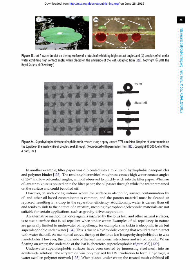
28
rsta.royalsocietypublishing.orgPhil.Trans.R.Soc.A374:20160135
.........................................................
air
water
water droplets
oil droplets
lotus leaf(b)(a)
Figure 23. (a) A water droplet on the top surface of a lotus leaf exhibiting high contact angles and (b) droplets of oil underwater exhibiting high contact angles when placed on the underside of the leaf. (Adapted from [129]. Copyright 2011 TheRoyal Society of Chemistry.)
water
diesel oil
100 mm
Figure 24. Superhydrophobic/superoleophilic mesh created using a spray-coated PTFE emulsion. Droplets of water remain onthe topside of themeshwhile oil droplets soak through. (Reproducedwith permission from [132]. Copyright 2004 JohnWiley& Sons, Inc.)
In another example, filter paper was dip coated into a mixture of hydrophobic nanoparticlesand polymer binder [133]. The resulting hierarchical roughness causes high water contact anglesof 157◦ and low oil contact angles, with oil observed to quickly wick into the filter paper. When anoil–water mixture is poured onto the filter paper, the oil passes through while the water remainedon the surface and could be rolled off.
However, in such configurations where the surface is oleophilic, surface contamination byoil and other oil-based contaminants is common, and the porous material must be cleaned orreplaced, resulting in a drop in the separation efficiency. Additionally, water is denser than oiland tends to sink to the bottom of a mixture, meaning hydrophobic/oleophilic materials are notsuitable for certain applications, such as gravity-driven separation.
An alternative method that once again is inspired by the lotus leaf, and other natural surfaces,is to use a surface that is oil repellent when under water. Examples of oil repellency in natureare generally limited to underwater oil repellency; for example, shark skin is oleophilic in air butsuperoleophobic under water [134]. This is due to a hydrophilic coating that would rather interactwith water than oil. As mentioned above, the top of the lotus leaf is superhydrophobic due to waxnanotubules. However, the underside of the leaf has no such structures and is hydrophilic. Whenfloating on water, the underside of the leaf is, therefore, superoleophobic (figure 23b) [129].
Underwater superoleophobic surfaces have been created by immersing steel mesh into anacrylamide solution. The acrylamide was polymerized by UV irradiation to form a hydrogel, awater-swollen polymer network [135]. When placed under water, the treated mesh exhibited oil
on June 28, 2016http://rsta.royalsocietypublishing.org/Downloaded from

29
rsta.royalsocietypublishing.orgPhil.Trans.R.Soc.A374:20160135
.........................................................
water water
water
oil
oil
coatedmesh
oil
substrate substrate
Figure 25. Underwater superoleophobic mesh created using a hydrogel coating. Oil droplets roll from the mesh when placedunder water. (Reproduced with permission from [135]. Copyright 2011 John Wiley & Sons, Inc.)
contact angles of 153◦ and droplets were found to roll easily from a tilted surface. When an oil–water mixture was poured onto the mesh, the water permeated through the mesh while the oilremained on top (figure 25). Although this configuration helps reduce the impact of fouling, thefact that the surface is only superoleophobic under water limits its application.
Surfaces that are superoleophobic in air are typically also superhydrophobic due to waterhaving a higher surface tension. Such surfaces would, therefore, be unsuitable for oil–waterseparation as the interactions with both liquids are similar.
However, it is possible to create a coating that repels oils but has an affinity for water [136–141]. This is achieved through the use of a fluorosurfactant, which contains a high-surface-energyhead group and a low-surface-energy tail group. Fluorosurfactants are typically used as additivesin paints or cleaners. However, the presence of the ionic head group in many examples allowsfor complexation, either in solution or on a coating, with polyelectrolytes. After deposition, thefluorinated tails segregate at the air interface, resulting in a low-surface-energy barrier that repelsoils. However, when droplets of water are placed on the surface, they are able to penetrate downthrough the tail groups to reach the high-surface-energy groups below [142]. The coating thereforeappears hydrophilic while also being oleophobic. However, many examples of these surfaces haveseveral drawbacks, including poor oleophobicity [143–145] or poor water penetration, resultingin a coating that is initially hydrophobic [139,145–148].
Brown & Bhushan [141] have created a superhydrophilic/superoleophobic surface bycombining the chemistry of the fluorosurfactant with hierarchical roughness inspired by the lotusleaf [141] (figure 26). The fluorosurfactant provides oil repellency and water affinity, while theroughness enhances these properties to result in oil contact angles of greater than 150◦ and watercontact angles of less than 5◦. When this coating is applied to a steel mesh and an oil–watermixture is poured over it, the water penetrates through the mesh while the oil remains on topand can be easily rolled off by tilting. By inclining the mesh at an angle, the two liquids can beseparated and collected simultaneously.
Such surfaces represent the ideal scenario for oil/water separators. Their oil-repellent naturemeans they are less prone to fouling than devices where the water phase is being repelled.In addition, their water affinity makes them more compatible with gravity-driven separation,where the water phase will be at the bottom of the mixture, or in scenarios where water is thedominant phase. The use of nanoparticles enhances the oil repellency and water affinity, ensuringgood separation efficiencies as well as quick penetration by the water phase. The nanoparticles
on June 28, 2016http://rsta.royalsocietypublishing.org/Downloaded from

30
rsta.royalsocietypublishing.orgPhil.Trans.R.Soc.A374:20160135
.........................................................
(a)
(b)
(c)
fluorosurfactant layer (FL)PDDA binder (2)–
–
–
+
+SiO2 nanoparticlesPDDA binder (1)glass
flat PDDA/FL
oil/watermixture
oilwater
layer-by-layercomposite
100
100 mm
1 mm0 mm
0100 mm
100 nm0 nm
0
–100nm
1
–1mm
Figure 26. Superoleophobic/superhydrophilic mesh created using spray-coated layer-by-layer technique. (a) Coatingcomprises fluorosurfactant layer for oil repellency and water affinity, SiO2 nanoparticle layer to enhance surface properties andincreased durability, and binder layers for adhesion. (b) AFM wear experiments (one cycle at 10µN) demonstrate increaseddurability of layer-by-layer coating compared with flat coating. (c) Oil–water separation ability of coated mesh [141].
also increase the hardness, resulting in a coating that is much more durable than previousexamples [141,149].
Importantly, unlike absorbent materials, both phases are immediately separated, with noadditional steps required to remove one phase from the material. It is envisioned that such adevice could be used upstream of the conventional purification membranes detailed above. Thisensures that the majority of the contaminant phase is removed before further purification andprocessing, resulting in greater efficiency of the more selective membranes.
(a) OutlookDespite advances in other energy sources, with a global population reaching 8.2 billion by2030 [4], oil and gas will continue to play an important role in meeting rising energy demand.
on June 28, 2016http://rsta.royalsocietypublishing.org/Downloaded from

31
rsta.royalsocietypublishing.orgPhil.Trans.R.Soc.A374:20160135
.........................................................
Nets featuring bioinspired coated mesh trapoils while allowing passage of water. Oil caneasily be recovered from nets via pumping.Oil-repellent nature of mesh reduces need
for cleaning.
bioinspired netsabsorbent boom
oil
oil-freewater
bioinspiredcoated
net
absorbentboom
Booms require favourable conditions, includingcalm waters and slow oil speeds. Oil caneasily slip under or be washed over the
boom. Extra steps required to extract oil frombooms. Booms require regular cleaning or
replacement.
Figure 27. Comparison of absorbent booms commonly used during oil-spill remediation and bioinspired nets. The boomsabsorb the oil from the surface of the water but require favourable conditions and must be regularly cleaned to recover theoil. The bioinspired nets will capture the oil, where it can be recovered by pumping, while allowing water to pass through.(Online version in colour.)
This, combined with the increase in fracking, makes future oil spills and contamination of waterincreasingly likely.
One current method for remediation of oil spills consists of absorbent booms that requirefavourable conditions and must be cleaned before the oil can be recovered (figure 27). Combininghierarchical roughness, inspired by the lotus leaf, with chemistries not available to naturehas resulted in materials that can separate oil from water. Specially coated nets could aidoil-spill clean-up by trapping the oil in the net while allowing the water to pass through(figure 27). Future challenges include improving the selectivity of these devices to achieve higherseparation efficiencies, without compromising the permeabilities that set these materials apartfrom traditional purification membranes. Such materials are also of relevance in a wide rangeof applications, including treatment of wastewater from the metal, textile or food processingindustries, and for scenarios where contaminant water must be removed from oil, for instancein engine components.
5. Concluding remarksWater is the key to all life. It was the medium into which life itself began. It is vital for not just oursurvival, but also the survival of all living things on the planet. Over some 3 billion years, variousspecies have evolved ingenious ways to collect and transport this vital fluid. From the hydrophilicspots on a beetle’s back, to the tiny proteins lining our cells, their size and complexity may varybut their purpose remains the same: to get water to where it is needed. By taking inspiration fromnature’s ingenuity, it is hoped we can solve our own water crisis through the creation of materialsfor water collection, water purification and separation of water from oil (figure 28).
When looking to nature, one thing that is immediately clear is its abundance. Nature is able tothrive in the harshest environments, including some of the driest places on the Earth. One way itdoes this is by using alternative sources of water, such as fog. By studying these examples, frombeetles to cacti, it is hoped that new materials can be developed to help improve the efficiency ofexisting fog-harvesting strategies and further establish the technique as a viable source of waterfor communities all over the world.
on June 28, 2016http://rsta.royalsocietypublishing.org/Downloaded from

32
rsta.royalsocietypublishing.orgPhil.Trans.R.Soc.A374:20160135
.........................................................
contaminated water
membrane cleanwater
watermolecules
oil-free watercollected oil
collected water
water collector
fog
oil-spill
separation from oil
bioinspired materialsfor water supply and
management
colle
ctio
npurification
contaminants
Figure 28. Bioinspired materials for water supply and management: collection, purification and separation from oil.
Purification of salt water, from the oceans or brackish groundwater, could also providean abundant source of water for many regions. However, the process of desalination isenergy-intensive. Nature has evolved efficient pathways in our own body to facilitate thetransport of water while blocking other species. It is hoped that, by taking inspiration fromthe chemistries and structures of these natural channels, artificial ones can be created that canimprove not just desalination efforts, but also purification of other water sources that too easilybecome contaminated, often by human activities.
In that vein, contamination of water by oil is a problem that has plagued human progress inthe last few centuries. This relatively new resource is constantly threatening sources of water,and while it is always hoped that large-scale oil spills are a thing of the past, disasters such asDeepwater Horizon show us that, so long as oil is sought, the danger will be there. Once again,we can learn from nature and, by studying how natural surfaces interact with liquids, can developnew techniques for cleaning up the mess that we, regrettably, continue to make.
Water is a human right [1]. However, it is a right that is currently under threat for manypeople across the world, including some in the United States, one of the most developed andeconomically stable countries in the world. It is hoped that nature can provide us with the toolswe need to help restore this right to all people.
Competing interests. We declare we have no competing interests.Funding. We received no funding for this study.Acknowledgements. Many thanks to Dev Gurera for creating several figures for this review and to Renée Ripleyfor creating figures and providing helpful suggestions and corrections.
on June 28, 2016http://rsta.royalsocietypublishing.org/Downloaded from

33
rsta.royalsocietypublishing.orgPhil.Trans.R.Soc.A374:20160135
.........................................................
vapourglv
gls
q
qadv qadv
qrec
qrec
gsv
liquid
solid
completewetting
originalposition
high hysteresis low hysteresis
Wenzel state Cassie–Baxter state
airpockets
(a)
(b)
(d)
(c)
(e)
Figure 29. (a) Liquid droplet displaying contact angle of θ on flat surface, (b) droplet exhibiting Wenzel state of wetting,(c) trapped air between droplet and surface in Cassie–Baxter state of wetting, (d) droplet exhibiting high contact anglehysteresis and (e) droplet exhibiting low contact angle hysteresis. (Online version in colour.)
Appendix A. Background on surface wettabilityThe ability to control liquid droplets is made possible by altering how they interact with thesurface upon which they are resting. A droplet of water on a solid surface forms a sphericalshape, which is determined by a combination of interfacial tensions,
cos θ = γsv − γsl
γlv, (A 1)
where γsv, γsl and γlv are the solid–vapour, solid–liquid and liquid–vapour surface tensions,respectively, and θ is the contact angle of the resulting droplet (figure 29a). Water contact angles<90◦ result in a surface that is considered hydrophilic (water loving), whereas surfaces exhibitingangles >90◦ are hydrophobic (water fearing) [9].
When a surface is roughened, contact angles change due to amplification of the solid–liquidinteractions; hydrophilic surfaces become more hydrophilic and hydrophobic surfaces morehydrophobic (figure 29b) [150]. It is also possible for air pockets to become trapped between thesolid and the liquid, resulting in a composite interface and, as the liquid is resting partially on air,a more repellent surface (figure 29c) [151].
However, a rough surface can exhibit contact angle hysteresis. This is where the contact anglesof a mobile drop are different for the leading edge and the trailing edge (figure 29d). As the leadingedge of a droplet moves, it does so with a certain contact angle known as the advancing contactangle (θadv). When the trailing edge begins to move, it will do so with a receding contact angle(θrec). The advancing and receding edges may have different respective contact angles; this is thecontact angle hysteresis. Typically, a low hysteresis is preferred to ensure the water droplets rollover the surface easily (figure 29e) [9].
on June 28, 2016http://rsta.royalsocietypublishing.org/Downloaded from
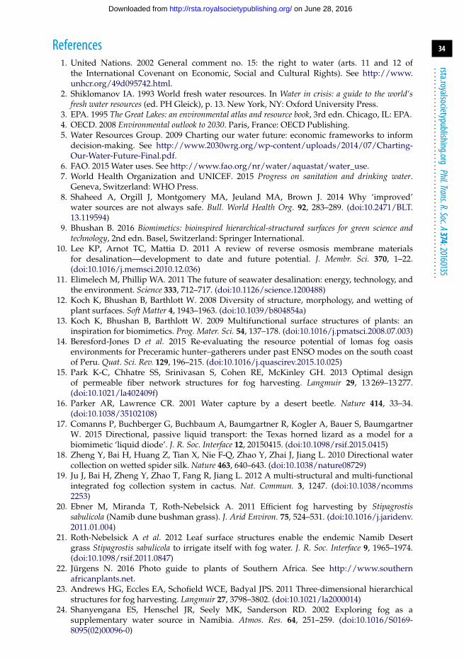
34
rsta.royalsocietypublishing.orgPhil.Trans.R.Soc.A374:20160135
.........................................................
References1. United Nations. 2002 General comment no. 15: the right to water (arts. 11 and 12 of
the International Covenant on Economic, Social and Cultural Rights). See http://www.unhcr.org/49d095742.html.
2. Shiklomanov IA. 1993 World fresh water resources. In Water in crisis: a guide to the world‘sfresh water resources (ed. PH Gleick), p. 13. New York, NY: Oxford University Press.
3. EPA. 1995 The Great Lakes: an environmental atlas and resource book, 3rd edn. Chicago, IL: EPA.4. OECD. 2008 Environmental outlook to 2030. Paris, France: OECD Publishing.5. Water Resources Group. 2009 Charting our water future: economic frameworks to inform
decision-making. See http://www.2030wrg.org/wp-content/uploads/2014/07/Charting-Our-Water-Future-Final.pdf.
6. FAO. 2015 Water uses. See http://www.fao.org/nr/water/aquastat/water_use.7. World Health Organization and UNICEF. 2015 Progress on sanitation and drinking water.
Geneva, Switzerland: WHO Press.8. Shaheed A, Orgill J, Montgomery MA, Jeuland MA, Brown J. 2014 Why ‘improved’
water sources are not always safe. Bull. World Health Org. 92, 283–289. (doi:10.2471/BLT.13.119594)
9. Bhushan B. 2016 Biomimetics: bioinspired hierarchical-structured surfaces for green science andtechnology, 2nd edn. Basel, Switzerland: Springer International.
10. Lee KP, Arnot TC, Mattia D. 2011 A review of reverse osmosis membrane materialsfor desalination—development to date and future potential. J. Membr. Sci. 370, 1–22.(doi:10.1016/j.memsci.2010.12.036)
11. Elimelech M, Phillip WA. 2011 The future of seawater desalination: energy, technology, andthe environment. Science 333, 712–717. (doi:10.1126/science.1200488)
12. Koch K, Bhushan B, Barthlott W. 2008 Diversity of structure, morphology, and wetting ofplant surfaces. Soft Matter 4, 1943–1963. (doi:10.1039/b804854a)
13. Koch K, Bhushan B, Barthlott W. 2009 Multifunctional surface structures of plants: aninspiration for biomimetics. Prog. Mater. Sci. 54, 137–178. (doi:10.1016/j.pmatsci.2008.07.003)
14. Beresford-Jones D et al. 2015 Re-evaluating the resource potential of lomas fog oasisenvironments for Preceramic hunter–gatherers under past ENSO modes on the south coastof Peru. Quat. Sci. Rev. 129, 196–215. (doi:10.1016/j.quascirev.2015.10.025)
15. Park K-C, Chhatre SS, Srinivasan S, Cohen RE, McKinley GH. 2013 Optimal designof permeable fiber network structures for fog harvesting. Langmuir 29, 13 269–13 277.(doi:10.1021/la402409f)
16. Parker AR, Lawrence CR. 2001 Water capture by a desert beetle. Nature 414, 33–34.(doi:10.1038/35102108)
17. Comanns P, Buchberger G, Buchbaum A, Baumgartner R, Kogler A, Bauer S, BaumgartnerW. 2015 Directional, passive liquid transport: the Texas horned lizard as a model for abiomimetic ‘liquid diode’. J. R. Soc. Interface 12, 20150415. (doi:10.1098/rsif.2015.0415)
18. Zheng Y, Bai H, Huang Z, Tian X, Nie F-Q, Zhao Y, Zhai J, Jiang L. 2010 Directional watercollection on wetted spider silk. Nature 463, 640–643. (doi:10.1038/nature08729)
19. Ju J, Bai H, Zheng Y, Zhao T, Fang R, Jiang L. 2012 A multi-structural and multi-functionalintegrated fog collection system in cactus. Nat. Commun. 3, 1247. (doi:10.1038/ncomms2253)
20. Ebner M, Miranda T, Roth-Nebelsick A. 2011 Efficient fog harvesting by Stipagrostissabulicola (Namib dune bushman grass). J. Arid Environ. 75, 524–531. (doi:10.1016/j.jaridenv.2011.01.004)
21. Roth-Nebelsick A et al. 2012 Leaf surface structures enable the endemic Namib Desertgrass Stipagrostis sabulicola to irrigate itself with fog water. J. R. Soc. Interface 9, 1965–1974.(doi:10.1098/rsif.2011.0847)
22. Jürgens N. 2016 Photo guide to plants of Southern Africa. See http://www.southernafricanplants.net.
23. Andrews HG, Eccles EA, Schofield WCE, Badyal JPS. 2011 Three-dimensional hierarchicalstructures for fog harvesting. Langmuir 27, 3798–3802. (doi:10.1021/la2000014)
24. Shanyengana ES, Henschel JR, Seely MK, Sanderson RD. 2002 Exploring fog as asupplementary water source in Namibia. Atmos. Res. 64, 251–259. (doi:10.1016/S0169-8095(02)00096-0)
on June 28, 2016http://rsta.royalsocietypublishing.org/Downloaded from
35
rsta.royalsocietypublishing.orgPhil.Trans.R.Soc.A374:20160135
.........................................................
25. Hamilton WJ, Seely MK. 1976 Fog basking by the Namib Desert beetle, Onymacrisunguicularis. Nature 262, 284–285. (doi:10.1038/262284a0)
26. Garrod RP, Harris LG, Schofield WCE, McGettrick J, Ward LJ, Teare DOH, Badyal JPS. 2007Mimicking a Stenocara beetle’s back for microcondensation using plasmachemical patternedsuperhydrophobic–superhydrophilic surfaces. Langmuir 23, 689–693. (doi:10.1021/la0610856)
27. Mondal B, Eain MMG, Xu Q, Egan VM, Punch J, Lyons AM. 2015 Design and fabrication ofa hybrid superhydrophobic–hydrophilic surface that exhibits stable dropwise condensation.ACS Appl. Mater. Interfaces 7, 23 575–23 588. (doi:10.1021/acsami.5b06759)
28. Wang Y, Zhang L, Wu J, Hedhili MN, Wang P. 2015 A facile strategy for the fabricationof a bioinspired hydrophilic–superhydrophobic patterned surface for highly efficient fog-harvesting. J. Mater. Chem. A 3, 18 963–18 969. (doi:10.1039/C5TA04930J)
29. Wong I, Teo GH, Neto C, Thickett SC. 2015 Micropatterned surfaces for atmospheric watercondensation via controlled radical polymerization and thin film dewetting. ACS Appl.Mater. Interfaces 7, 21 562–21 570. (doi:10.1021/acsami.5b06856)
30. Zhang L, Wu J, Hedhili MN, Yang X, Wang P. 2015 Inkjet printing for direct micropatterningof a superhydrophobic surface: toward biomimetic fog harvesting surfaces. J. Mater. Chem. A3, 2844–2852. (doi:10.1039/C4TA05862C)
31. Zhai L, Berg MC, Cebeci FC, Kim Y, Milwid JM, Rubner MF, Cohen RE. 2006 Patternedsuperhydrophobic surfaces: toward a synthetic mimic of the Namib Desert beetle. Nano Lett.6, 1213–1217. (doi:10.1021/nl060644q)
32. Dorrer C, Rühe J. 2008 Mimicking the Stenocara beetle—dewetting of drops from a patternedsuperhydrophobic surface. Langmuir 24, 6154–6158. (doi:10.1021/la800226e)
33. Bentley PJ, Blumer WFC. 1962 Uptake of water by the lizard, Moloch horridus. Nature 194,699–700. (doi:10.1038/194699a0)
34. Schwenk K, Greene HW. 1987 Water collection and drinking in Phrynocephalus helioscopus: apossible condensation mechanism. J. Herpetol. 21, 134–139. (doi:10.2307/1564473)
35. Comanns P, Effertz C, Hischen F, Staudt K, Böhme W, Baumgartner W. 2011 Moistureharvesting and water transport through specialized micro-structures on the integument oflizards. Beilstein J. Nanotechnol. 2, 204–214. (doi:10.3762/bjnano.2.24)
36. Becker N, Oroudjev E, Mutz S, Cleveland JP, Hansma PK, Hayashi CY, Makarov DE,Hansma HG. 2003 Molecular nanosprings in spider capture-silk threads. Nat. Mater. 2,278–283. (doi:10.1038/nmat858)
37. Edmonds DT, Vollrath F. 1992 The contribution of atmospheric water vapour to theformation and efficiency of a spider’s capture web. Proc. R. Soc. Lond. B 248, 145–148.(doi:10.1098/rspb.1992.0055)
38. Lorenceau É, Quéré D. 2004 Drops on a conical wire. J. Fluid Mech. 510, 29–45.(doi:10.1017/S0022112004009152)
39. Bai H, Tian X, Zheng Y, Ju J, Zhao Y, Jiang L. 2010 Direction controlled driving of tinywater drops on bioinspired artificial spider silks. Adv. Mater. 22, 5521–5525. (doi:10.1002/adma.201003169)
40. Dong H, Wang N, Wang L, Bai H, Wu J, Zheng Y, Zhao Y, Jiang L. 2012 Bioinspiredelectrospun knotted microfibers for fog harvesting. ChemPhysChem 13, 1153–1156.(doi:10.1002/cphc.201100957)
41. Chen Y, Wang L, Xue Y, Jiang L, Zheng Y. 2013 Bioinspired tilt-angle fabricatedstructure gradient fibers: micro-drops fast transport in a long-distance. Sci. Rep. 3, 2927.(doi:10.1038/srep02927)
42. Bai H, Ju J, Sun R, Chen Y, Zheng Y, Jiang L. 2011 Controlled fabrication andwater collection ability of bioinspired artificial spider silks. Adv. Mater. 23, 3708–3711.(doi:10.1002/adma.201101740)
43. Ogburn RM, Edwards EJ. 2009 Anatomical variation in Cactaceae and relatives: trait labilityand evolutionary innovation. Am. J. Bot. 96, 391–408. (doi:10.3732/ajb.0800142)
44. Mooney HA, Weisser PJ, Gulmon SL. 1977 Environmental adaptations of the Atacama Desertcactus Copiapoa haseltoniana. Flora 166, 117–124.
45. Vesilind PJ. 2003 Atacama Desert. National Geographic (August, 2003). See http://ngm.nationalgeographic.com/features/world/south-america/chile/atacama-text.
46. Liu C, Xue Y, Chen Y, Zheng Y. 2015 Effective directional self-gathering of drops on spine ofcactus with splayed capillary arrays. Sci. Rep. 5, 17757. (doi:10.1038/srep17757)
on June 28, 2016http://rsta.royalsocietypublishing.org/Downloaded from
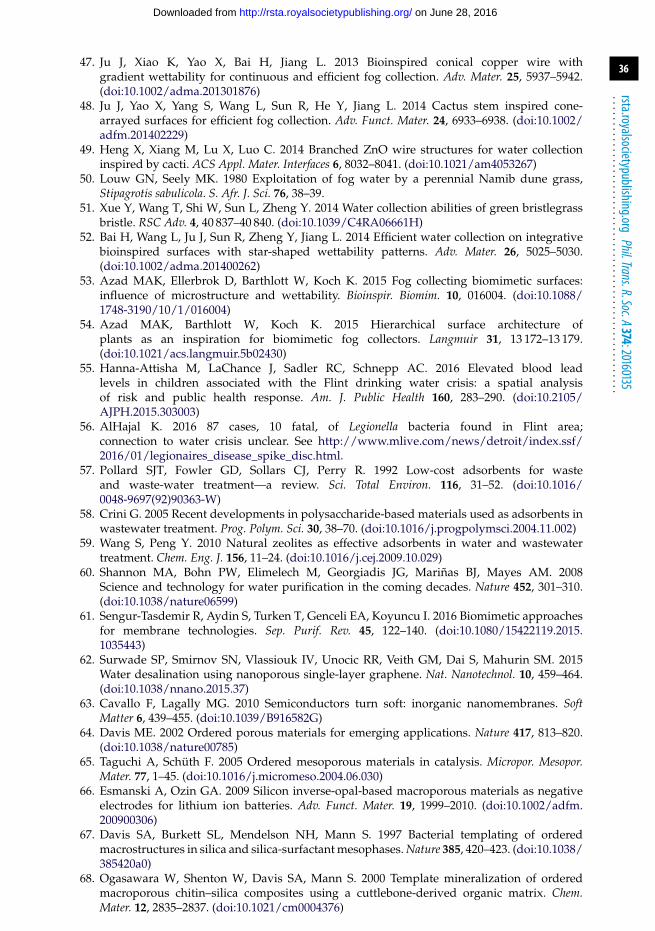
36
rsta.royalsocietypublishing.orgPhil.Trans.R.Soc.A374:20160135
.........................................................
47. Ju J, Xiao K, Yao X, Bai H, Jiang L. 2013 Bioinspired conical copper wire withgradient wettability for continuous and efficient fog collection. Adv. Mater. 25, 5937–5942.(doi:10.1002/adma.201301876)
48. Ju J, Yao X, Yang S, Wang L, Sun R, He Y, Jiang L. 2014 Cactus stem inspired cone-arrayed surfaces for efficient fog collection. Adv. Funct. Mater. 24, 6933–6938. (doi:10.1002/adfm.201402229)
49. Heng X, Xiang M, Lu X, Luo C. 2014 Branched ZnO wire structures for water collectioninspired by cacti. ACS Appl. Mater. Interfaces 6, 8032–8041. (doi:10.1021/am4053267)
50. Louw GN, Seely MK. 1980 Exploitation of fog water by a perennial Namib dune grass,Stipagrotis sabulicola. S. Afr. J. Sci. 76, 38–39.
51. Xue Y, Wang T, Shi W, Sun L, Zheng Y. 2014 Water collection abilities of green bristlegrassbristle. RSC Adv. 4, 40 837–40 840. (doi:10.1039/C4RA06661H)
52. Bai H, Wang L, Ju J, Sun R, Zheng Y, Jiang L. 2014 Efficient water collection on integrativebioinspired surfaces with star-shaped wettability patterns. Adv. Mater. 26, 5025–5030.(doi:10.1002/adma.201400262)
53. Azad MAK, Ellerbrok D, Barthlott W, Koch K. 2015 Fog collecting biomimetic surfaces:influence of microstructure and wettability. Bioinspir. Biomim. 10, 016004. (doi:10.1088/1748-3190/10/1/016004)
54. Azad MAK, Barthlott W, Koch K. 2015 Hierarchical surface architecture ofplants as an inspiration for biomimetic fog collectors. Langmuir 31, 13 172–13 179.(doi:10.1021/acs.langmuir.5b02430)
55. Hanna-Attisha M, LaChance J, Sadler RC, Schnepp AC. 2016 Elevated blood leadlevels in children associated with the Flint drinking water crisis: a spatial analysisof risk and public health response. Am. J. Public Health 160, 283–290. (doi:10.2105/AJPH.2015.303003)
56. AlHajal K. 2016 87 cases, 10 fatal, of Legionella bacteria found in Flint area;connection to water crisis unclear. See http://www.mlive.com/news/detroit/index.ssf/2016/01/legionaires_disease_spike_disc.html.
57. Pollard SJT, Fowler GD, Sollars CJ, Perry R. 1992 Low-cost adsorbents for wasteand waste-water treatment—a review. Sci. Total Environ. 116, 31–52. (doi:10.1016/0048-9697(92)90363-W)
58. Crini G. 2005 Recent developments in polysaccharide-based materials used as adsorbents inwastewater treatment. Prog. Polym. Sci. 30, 38–70. (doi:10.1016/j.progpolymsci.2004.11.002)
59. Wang S, Peng Y. 2010 Natural zeolites as effective adsorbents in water and wastewatertreatment. Chem. Eng. J. 156, 11–24. (doi:10.1016/j.cej.2009.10.029)
60. Shannon MA, Bohn PW, Elimelech M, Georgiadis JG, Mariñas BJ, Mayes AM. 2008Science and technology for water purification in the coming decades. Nature 452, 301–310.(doi:10.1038/nature06599)
61. Sengur-Tasdemir R, Aydin S, Turken T, Genceli EA, Koyuncu I. 2016 Biomimetic approachesfor membrane technologies. Sep. Purif. Rev. 45, 122–140. (doi:10.1080/15422119.2015.1035443)
62. Surwade SP, Smirnov SN, Vlassiouk IV, Unocic RR, Veith GM, Dai S, Mahurin SM. 2015Water desalination using nanoporous single-layer graphene. Nat. Nanotechnol. 10, 459–464.(doi:10.1038/nnano.2015.37)
63. Cavallo F, Lagally MG. 2010 Semiconductors turn soft: inorganic nanomembranes. SoftMatter 6, 439–455. (doi:10.1039/B916582G)
64. Davis ME. 2002 Ordered porous materials for emerging applications. Nature 417, 813–820.(doi:10.1038/nature00785)
65. Taguchi A, Schüth F. 2005 Ordered mesoporous materials in catalysis. Micropor. Mesopor.Mater. 77, 1–45. (doi:10.1016/j.micromeso.2004.06.030)
66. Esmanski A, Ozin GA. 2009 Silicon inverse-opal-based macroporous materials as negativeelectrodes for lithium ion batteries. Adv. Funct. Mater. 19, 1999–2010. (doi:10.1002/adfm.200900306)
67. Davis SA, Burkett SL, Mendelson NH, Mann S. 1997 Bacterial templating of orderedmacrostructures in silica and silica-surfactant mesophases. Nature 385, 420–423. (doi:10.1038/385420a0)
68. Ogasawara W, Shenton W, Davis SA, Mann S. 2000 Template mineralization of orderedmacroporous chitin–silica composites using a cuttlebone-derived organic matrix. Chem.Mater. 12, 2835–2837. (doi:10.1021/cm0004376)
on June 28, 2016http://rsta.royalsocietypublishing.org/Downloaded from
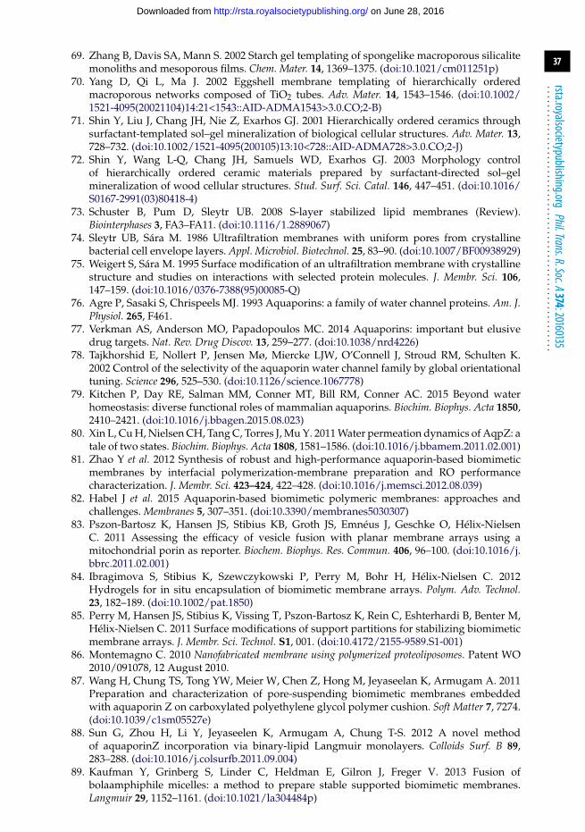
37
rsta.royalsocietypublishing.orgPhil.Trans.R.Soc.A374:20160135
.........................................................
69. Zhang B, Davis SA, Mann S. 2002 Starch gel templating of spongelike macroporous silicalitemonoliths and mesoporous films. Chem. Mater. 14, 1369–1375. (doi:10.1021/cm011251p)
70. Yang D, Qi L, Ma J. 2002 Eggshell membrane templating of hierarchically orderedmacroporous networks composed of TiO2 tubes. Adv. Mater. 14, 1543–1546. (doi:10.1002/1521-4095(20021104)14:21<1543::AID-ADMA1543>3.0.CO;2-B)
71. Shin Y, Liu J, Chang JH, Nie Z, Exarhos GJ. 2001 Hierarchically ordered ceramics throughsurfactant-templated sol–gel mineralization of biological cellular structures. Adv. Mater. 13,728–732. (doi:10.1002/1521-4095(200105)13:10<728::AID-ADMA728>3.0.CO;2-J)
72. Shin Y, Wang L-Q, Chang JH, Samuels WD, Exarhos GJ. 2003 Morphology controlof hierarchically ordered ceramic materials prepared by surfactant-directed sol–gelmineralization of wood cellular structures. Stud. Surf. Sci. Catal. 146, 447–451. (doi:10.1016/S0167-2991(03)80418-4)
73. Schuster B, Pum D, Sleytr UB. 2008 S-layer stabilized lipid membranes (Review).Biointerphases 3, FA3–FA11. (doi:10.1116/1.2889067)
74. Sleytr UB, Sára M. 1986 Ultrafiltration membranes with uniform pores from crystallinebacterial cell envelope layers. Appl. Microbiol. Biotechnol. 25, 83–90. (doi:10.1007/BF00938929)
75. Weigert S, Sára M. 1995 Surface modification of an ultrafiltration membrane with crystallinestructure and studies on interactions with selected protein molecules. J. Membr. Sci. 106,147–159. (doi:10.1016/0376-7388(95)00085-Q)
76. Agre P, Sasaki S, Chrispeels MJ. 1993 Aquaporins: a family of water channel proteins. Am. J.Physiol. 265, F461.
77. Verkman AS, Anderson MO, Papadopoulos MC. 2014 Aquaporins: important but elusivedrug targets. Nat. Rev. Drug Discov. 13, 259–277. (doi:10.1038/nrd4226)
78. Tajkhorshid E, Nollert P, Jensen Mø, Miercke LJW, O’Connell J, Stroud RM, Schulten K.2002 Control of the selectivity of the aquaporin water channel family by global orientationaltuning. Science 296, 525–530. (doi:10.1126/science.1067778)
79. Kitchen P, Day RE, Salman MM, Conner MT, Bill RM, Conner AC. 2015 Beyond waterhomeostasis: diverse functional roles of mammalian aquaporins. Biochim. Biophys. Acta 1850,2410–2421. (doi:10.1016/j.bbagen.2015.08.023)
80. Xin L, Cu H, Nielsen CH, Tang C, Torres J, Mu Y. 2011 Water permeation dynamics of AqpZ: atale of two states. Biochim. Biophys. Acta 1808, 1581–1586. (doi:10.1016/j.bbamem.2011.02.001)
81. Zhao Y et al. 2012 Synthesis of robust and high-performance aquaporin-based biomimeticmembranes by interfacial polymerization-membrane preparation and RO performancecharacterization. J. Membr. Sci. 423–424, 422–428. (doi:10.1016/j.memsci.2012.08.039)
82. Habel J et al. 2015 Aquaporin-based biomimetic polymeric membranes: approaches andchallenges. Membranes 5, 307–351. (doi:10.3390/membranes5030307)
83. Pszon-Bartosz K, Hansen JS, Stibius KB, Groth JS, Emnéus J, Geschke O, Hélix-NielsenC. 2011 Assessing the efficacy of vesicle fusion with planar membrane arrays using amitochondrial porin as reporter. Biochem. Biophys. Res. Commun. 406, 96–100. (doi:10.1016/j.bbrc.2011.02.001)
84. Ibragimova S, Stibius K, Szewczykowski P, Perry M, Bohr H, Hélix-Nielsen C. 2012Hydrogels for in situ encapsulation of biomimetic membrane arrays. Polym. Adv. Technol.23, 182–189. (doi:10.1002/pat.1850)
85. Perry M, Hansen JS, Stibius K, Vissing T, Pszon-Bartosz K, Rein C, Eshterhardi B, Benter M,Hélix-Nielsen C. 2011 Surface modifications of support partitions for stabilizing biomimeticmembrane arrays. J. Membr. Sci. Technol. S1, 001. (doi:10.4172/2155-9589.S1-001)
86. Montemagno C. 2010 Nanofabricated membrane using polymerized proteoliposomes. Patent WO2010/091078, 12 August 2010.
87. Wang H, Chung TS, Tong YW, Meier W, Chen Z, Hong M, Jeyaseelan K, Armugam A. 2011Preparation and characterization of pore-suspending biomimetic membranes embeddedwith aquaporin Z on carboxylated polyethylene glycol polymer cushion. Soft Matter 7, 7274.(doi:10.1039/c1sm05527e)
88. Sun G, Zhou H, Li Y, Jeyaseelen K, Armugam A, Chung T-S. 2012 A novel methodof aquaporinZ incorporation via binary-lipid Langmuir monolayers. Colloids Surf. B 89,283–288. (doi:10.1016/j.colsurfb.2011.09.004)
89. Kaufman Y, Grinberg S, Linder C, Heldman E, Gilron J, Freger V. 2013 Fusion ofbolaamphiphile micelles: a method to prepare stable supported biomimetic membranes.Langmuir 29, 1152–1161. (doi:10.1021/la304484p)
on June 28, 2016http://rsta.royalsocietypublishing.org/Downloaded from

38
rsta.royalsocietypublishing.orgPhil.Trans.R.Soc.A374:20160135
.........................................................
90. Li X, Wang R, Wicaksana F, Zhao Y, Tang C, Torres J, Fane AG. 2013 Fusion behaviour ofaquaporin Z incorporated proteoliposomes investigated by quartz crystal microbalance withdissipation (QCM-D). Colloids Surf. B 111, 446–452. (doi:10.1016/j.colsurfb.2013.06.008)
91. Kaufman Y, Berman A, Freger V. 2010 Supported lipid bilayer membranes for waterpurification by reverse osmosis. Langmuir 26, 7388–7395. (doi:10.1021/la904411b)
92. Kumar M, Grzelakowski M, Zilles J, Clark M, Meier W. 2007 Highly permeable polymericmembranes based on the incorporation of the functional water channel protein aquaporin Z.Proc. Natl Acad. Sci. USA 104, 20 719–20 724. (doi:10.1073/pnas.0708762104)
93. Ghadiri MR, Granja JR, Milligan RA, McRee DE, Khazanovich N. 1993 Self-assemblingorganic nanotubes based on a cyclic peptide architecture. Nature 366, 324–327. (doi:10.1038/366324a0)
94. Percec V, Dulcey AE, Peterca M, Adelman P, Samant R, Balagurusamy VSK, Heiney PA.2007 Helical pores self-assembled from homochiral dendritic dipeptides based on l-Tyr andnonpolar α-amino acids. J. Am. Chem. Soc. 129, 5992–6002. (doi:10.1021/ja071088k)
95. Hourani R, Zhang C, van der Weegen R, Ruiz L, Li C, Keten S, Helms BA, Xu T.2011 Processable cyclic peptide nanotubes with tunable interiors. J. Am. Chem. Soc. 133,15 296–15 299. (doi:10.1021/ja2063082)
96. Percec V et al. 2004 Self-assembly of amphiphilic dendritic dipeptides into helical pores.Nature 430, 764–768. (doi:10.1038/nature02770)
97. Cazacu A, Tong C, van der Lee A, Fyles TM, Barboiu M. 2006 Columnar self-assembledureido crown ethers: an example of ion-channel organization in lipid bilayers. J. Am. Chem.Soc. 128, 9541–9548. (doi:10.1021/ja061861w)
98. Negin S, Daschbach MM, Kulikov OV, Rath N, Gokel GW. 2011 Pore formation inphospholipid bilayers by branched-chain pyrogallol[4]arenes. J. Am. Chem. Soc. 133,3234–3237. (doi:10.1021/ja1085645)
99. Hummer G, Rasaiah JC, Noworyta JP. 2001 Water conduction through the hydrophobicchannel of a carbon nanotube. Nature 414, 188–190. (doi:10.1038/35102535)
100. Corry B. 2008 Designing carbon nanotube membranes for efficient water desalination. J. Phys.Chem. B 112, 1427–1434. (doi:10.1021/jp709845u)
101. Srivastava A, Srivastava ON, Talapatra S, Vajtai R, Ajayan PM. 2004 Carbon nanotube filters.Nat. Mater. 3, 610–614. (doi:10.1038/nmat1192)
102. Holt JK, Park HG, Wang Y, Stadermann M, Artyukhin AB, Grigoropoulos CP, Noy A,Bakajin O. 2006 Fast mass transport through sub-2-nanometer carbon nanotubes. Science 312,1034–1037. (doi:10.1126/science.1126298)
103. Fornasiero F, Park HG, Holt JK, Stadermann M, Grigoropoulos CP, Noy A, Bakajin O.2008 Ion exclusion by sub-2-nm carbon nanotube pores. Proc. Natl Acad. Sci. USA 105,17 250–17 255. (doi:10.1073/pnas.0710437105)
104. Liu G, Ding J. 1998 Diblock thin films with densely hexagonally packednanochannels. Adv. Mater. 10, 69–71. (doi:10.1002/(SICI)1521-4095(199801)10:1<69::AID-ADMA69>3.0.CO;2-N)
105. Phillip WA, Hillmyer MA, Cussler EL. 2010 Cylinder orientation mechanism inblock copolymer thin films upon solvent evaporation. Macromolecules 43, 7763–7770.(doi:10.1021/ma1012946)
106. Fukunaga K, Hashimoto T, Elbs H, Krausch G. 2002 Self-assembly of a lamellar ABC triblockcopolymer thin film. Macromolecules 35, 4406–4413. (doi:10.1021/ma011889m)
107. Yang SY, Ryu I, Kim HY, Kim JK, Jang SK, Russell TP. 2006 Nanoporous membraneswith ultrahigh selectivity and flux for the filtration of viruses. Adv. Mater. 18, 709–712.(doi:10.1002/adma.200501500)
108. Li X, Fustin C-A, Lefèvre N, Gohy J-F, De Feyter S, De Baerdemaeker J, Egger W,Vankelecom IFJ. 2010 Ordered nanoporous membranes based on diblock copolymers withhigh chemical stability and tunable separation properties. J. Mater. Chem. 20, 4333–4339.(doi:10.1039/b926774c)
109. Peinemann K-V, Abetz V, Simon PFW. 2007 Asymmetric superstructure formed in a blockcopolymer via phase separation. Nat. Mater. 6, 992–996. (doi:10.1038/nmat2038)
110. Mulvenna RA, Weidman JL, Jing B, Pople JA, Zhu J, Boudouris BW, Phillip WA. 2014Tunable nanoporous membranes with chemically-tailored pore walls from triblock polymertemplates. J. Membr. Sci. 470, 246–256. (doi:10.1016/j.memsci.2014.07.021)
on June 28, 2016http://rsta.royalsocietypublishing.org/Downloaded from

39
rsta.royalsocietypublishing.orgPhil.Trans.R.Soc.A374:20160135
.........................................................
111. Guillen G, Hoek EMV. 2009 Modeling the impacts of feed spacer geometry onreverse osmosis and nanofiltration processes. Chem. Eng. J. 149, 221–231. (doi:10.1016/j.cej.2008.10.030)
112. Keskin D, Clodt JI, Hahn J, Abetz V, Filiz V. 2014 Postmodification of PS-b-P4VP diblockcopolymer membranes by ARGET ATRP. Langmuir 30, 8907–8914. (doi:10.1021/la501478s)
113. Etkin DS, Welch J. 1997 Oil Spill Intelligence Report International Oil Spill Database: trendsin oil spill volumes and frequency. Int. Oil Spill Conf. Proc. 1997, 949–952. (doi:10.7901/2169-3358-1997-1-949)
114. Ramseur JL. 2015 Deepwater Horizon oil spill: recent activities and ongoing developments.See https://www.fas.org/sgp/crs/misc/R42942.pdf.
115. ITOPF. 2015 Oil tanker spill statistics. See http://www.itopf.com/knowledge-resources/data-statistics/statistics.
116. EIA. 2015 Crude oil production. See https://www.eia.gov/dnav/pet/pet_crd_crpdn_adc_mbblpd_m.htm.
117. Kondash A, Vengosh A. 2015 Water footprint of hydraulic fracturing. Environ. Sci. Technol.Lett. 2, 276–280. (doi:10.1021/acs.estlett.5b00211)
118. Begos K. 2014 4 states confirm water pollution from drilling. See http://www.usatoday.com/story/money/business/2014/01/05/some-states-confirm-water-pollution-from-drill-ing/4328859.
119. Nwaizuzu C, Joel OF, Sikoki FD. 2015 Evaluation of oil spill dispersants with a focus ontheir toxicity and biodegradability. SPE Nigeria Annu. Int. Conf. Exhibition, 4–6 August, Lagos,Nigeria, SPE-178321-MS. Society of Petroleum Engineers. (doi:10.2118/178321-MS)
120. Sakthivel T, Reid DL, Goldstein I, Hench L, Seal S. 2013 Hydrophobic high surface areazeolites derived from fly ash for oil spill remediation. Environ. Sci. Technol. 47, 5843–5850.(doi:10.1021/es3048174)
121. Alther GR. 1995 Organically modified clay removes oil from water. Waste Manage. 15,623–628. (doi:10.1016/0956-053X(96)00023-2)
122. Annunciado TR, Sydenstricker THD, Amico SC. 2005 Experimental investigation of variousvegetable fibers as sorbent materials for oil spills. Mar. Pollut. Bull. 50, 1340–1346.(doi:10.1016/j.marpolbul.2005.04.043)
123. Sun X-F, Sun R, Sun J-X. 2002 Acetylation of rice straw with or without catalysts and itscharacterization as a natural sorbent in oil spill cleanup. J. Agric. Food Chem. 50, 6428–6433.(doi:10.1021/jf020392o)
124. Teas CH, Kalligeros S, Zanikos F, Stournas S, Lois E, Anastopolous G. 2001 Investigationof the effectiveness of absorbent materials in oil spills clean up. Desalination 140, 259–264.(doi:10.1016/S0011-9164(01)00375-7)
125. Radetic MM, Jocic DM, Jovancic PM, Petrovic ZLJ, Thomas HF. 2003 Recycled wool-basednonwoven material as an oil sorbent. Environ. Sci. Technol. 37, 1008–1012. (doi:10.1021/es0201303)
126. Al-Majed AA, Adebayo AR, Hossain ME. 2012 A sustainable approach to controlling oilspills. J. Environ. Manage. 113, 213–227. (doi:10.1016/j.jenvman.2012.07.034)
127. Zhu G, Pan Q, Liu F. 2011 Facile removal and collection of oils from water surfacesthrough superhydrophobic and superoleophilic sponges. J. Phys. Chem. C 115, 17 464–17 470.(doi:10.1021/jp2043027)
128. Barthlott W, Neinhuis C. 1997 Purity of the sacred lotus, or escape from contamination inbiological surfaces. Planta 202, 1–8. (doi:10.1007/s004250050096)
129. Cheng Q, Li M, Zheng Y, Su B, Wang S, Jiang L. 2011 Janus interface materials:superhydrophobic air/solid interface and superoleophobic water/solid interface inspiredby a lotus leaf. Soft Matter 7, 5948–5951. (doi:10.1039/c1sm05452j)
130. Bhushan B, Jung YC. 2011 Natural and biomimetic artificial surfaces for superhydro-phobicity, self-cleaning, low adhesion, and drag reduction. Prog. Mater. Sci. 56, 1–108.(doi:10.1016/j.pmatsci.2010.04.003)
131. Brown PS, Bhushan B. 2016 Designing bioinspired superoleophobic surfaces. APL Mater. 4,015703. (doi:10.1063/1.4935126)
132. Feng L, Zhang Z, Mai Z, Ma Y, Liu B, Jiang L, Zhu D. 2004 A super-hydrophobic and super-oleophilic coating mesh film for the separation of oil and water. Angew. Chem. Int. Ed. 43,2012–2014. (doi:10.1002/anie.200353381)
on June 28, 2016http://rsta.royalsocietypublishing.org/Downloaded from

40
rsta.royalsocietypublishing.orgPhil.Trans.R.Soc.A374:20160135
.........................................................
133. Wang S, Li M, Lu Q. 2010 Filter paper with selective absorption and separation of liquids thatdiffer in surface tension. ACS Appl. Mater. Interfaces 2, 677–683. (doi:10.1021/am900704u)
134. Bixler G, Bhushan B. 2013 Fluid drag reduction and efficient self-cleaning with rice leaf andbutterfly wing bioinspired surfaces. Nanoscale 5, 7685–7710. (doi:10.1039/c3nr01710a)
135. Xue Z, Wang S, Lin L, Chen L, Liu M, Feng L, Jiang L. 2011 A novel superhydrophilic andunderwater superoleophobic hydrogel-coated mesh for oil/water separation. Adv. Mater. 23,4270–4273. (doi:10.1002/adma.201102616)
136. Goddard ED. 1986 Polymer–surfactant interaction. Part II. Polymer and surfactant ofopposite charge. Colloids Surf. 19, 301–329. (doi:10.1016/0166-6622(86)80341-9)
137. Antonetti M, Henke S, Thünemann A. 1996 Highly ordered materials with ultra-low surfaceenergies: polyelectrolyte–surfactant complexes with fluorinated surfactants. Adv. Mater. 8,41–45. (doi:10.1002/adma.19960080106)
138. Thünemann AF, Lochhaas KH. 1999 Surface and solid-state properties of a fluorinatedpolyelectrolyte–surfactant complex. Langmuir 15, 4867–4874. (doi:10.1021/la9900728)
139. Yang J, Song H, Yan X, Tang H, Li C. 2014 Superhydrophilic and superoleophobicchitosan-based nanocomposite coatings for oil/water separation. Cellulose 21, 1851–1857.(doi:10.1007/s10570-014-0244-0)
140. Brown PS, Atkinson ODLA, Badyal JPS. 2014 Ultrafast oleophobic–hydrophilic switchingsurfaces for antifogging, self-cleaning, and oil–water separation. ACS Appl. Mater. Interfaces6, 7504–7511. (doi:10.1021/am500882y)
141. Brown PS, Bhushan B. 2015 Mechanically durable, superoleophobic coatings prepared bylayer-by-layer technique for anti-smudge and oil–water separation. Sci. Rep. 5, 8701–8709.(doi:10.1038/srep08701)
142. Li L, Wang Y, Gallaschun C, Risch T, Sun J. 2012 Why can a nanometer-thick polymercoated surface be more wettable to water than to oil? J. Mater. Chem. 22, 16 719–11 672.(doi:10.1039/c2jm32580b)
143. Hutton SJ, Crowther JM, Badyal JPS. 2000 Complexation of fluorosurfactants tofunctionalized solid surfaces: smart behavior. Chem. Mater. 12, 2282–2286. (doi:10.1021/cm000123i)
144. Lampitt RA, Crowther JM, Badyal JPS. 2000 Switching liquid repellent surfaces. J. Phys. Chem.B 104, 10 329–10 331. (doi:10.1021/jp002234a)
145. Sawada H, Yoshioka H, Kawase T, Takahashi H, Abe A, Ohashi R. 2005 Synthesis andapplications of a variety of fluoroalkyl end-capped oligomers/silica gel polymer hybrids.J. Appl. Polym. Sci. 98, 169–177. (doi:10.1002/app.22034)
146. Sawada H, Ikematsu Y, Kawase T, Hayakawa Y. 1996 Synthesis and surface propertiesof novel fluoroalkylated flip-flop-type silane coupling agents. Langmuir 12, 3529–3530.(doi:10.1021/la951041p)
147. Yang J, Zhang Z, Xu X, Zhu X, Men X, Zhou X. 2012 Superhydrophilic–superoleophobiccoatings. J. Mater. Chem. 22, 2834–2837. (doi:10.1039/c2jm15987b)
148. Saito T, Tsushima Y, Sawada H. 2015 Facile creation of superoleophobic andsuperhydrophilic surface by using fluoroalkyl end-capped vinyltrimethoxysilaneoligomer/calcium silicide nanocomposites—development of these nanocomposites toenvironmental cyclical type-fluorine recycle through formation of calcium fluoride. ColloidPolym. Sci. 293, 65–73. (doi:10.1007/s00396-014-3387-5)
149. Brown PS, Bhushan B. 2015 Bioinspired, roughness-induced, water and oil super-philic andsuper-phobic coatings prepared by adaptable layer-by-layer technique. Sci. Rep. 5, 14030.(doi:10.1038/srep14030)
150. Wenzel RN. 1936 Resistance of solid surfaces to wetting by water. Ind. Eng. Chem. 28, 988–994.(doi:10.1021/ie50320a024)
151. Cassie ABD, Baxter S. 1944 Wettability of porous surfaces. Trans. Faraday Soc. 40, 546–551.(doi:10.1039/tf9444000546)
on June 28, 2016http://rsta.royalsocietypublishing.org/Downloaded from