biogas upgrading and bottling technology developed for vehicular applications · 2013-09-10 ·...
TRANSCRIPT
Biogas Upgrading and Bottling
Technology Developed for Vehicular
Applications
Prof. Virendra K. Vijay
Centre for Rural Development & Technology
Coordinator- BDTC
IIT Delhi

BIOGAS
• Energy source produced from biodegradable /organic wastes by
anaerobic digestion process
• Possible feedstock material: All good biodegradable organic materials
Digester sludge
Manure (liquid & solid)
Organic waste (Household waste, restaurant waste, food industry
waste, etc.)
Energy crops (silage of maize, grass, corn, etc.)
• Additional benefit of digested slurry - can be dried and sold as high
quality compost.
• Biogas belongs to the same gas-family as natural gas
• After upgrading biogas, calorific value, density and Wobbe Index are
almost similar to natural gas
• Biogas can be adapted to the quality of natural gas

Biogas in INDIA
• An estimate indicates that India has a potential of generating 6.38 X 10¹⁰ m3 of biogas from 980 million tones of cattle dung produced annually from 300 million cattle population.
• The heat value of this gas amounts to 1.3 X 10¹² MJ. In addition, 350 million tones of manure would also produce along with biogas.
• Apart from the 4.5 million domestic biogas plants installed in India against the potential of 12 million, there is a huge potential of installation of medium and large scale biogas plants installation in India in small scale industries, animal rearing farms, poultry farms, distilleries, tanneries, hotels, restaurants, military barracks etc.

0
5
10
15
20
25
30
35
40
40 million
4.4 million
222,500 150,000 35,000 6000 4000 75 49 24
Domestics Size Biogas Plants installed upto 2010 in some developing countries
Sources: Based on various source
India stands 2nd
amongst its peers

Potential
There are around 300
distilleries throughout India
which collectively have a
potential of producing 1200
million Nm3 biogas, and
2000 tannery units capable
of producing 787,500 Nm3
of biogas . The increasing
number of poultry farms can
also add to biogas
productivity as with a
current population of 649
million birds, another 2173
million Nm3 of biogas can
be generated.
0
2000
4000
6000
8000
10000
12000
Municipalliquid waste
MunicipalSolid waste
Press mud Food wastes Willow dust
12000
30 9 4.5 0.0085
MT/yr
Organic Solid Waste
Source: MNES Report, Renewable Energy in India and business opportunities, MNES. Govt. of India, New Delhi
0
100000
200000
300000
400000
500000
600000
Paper & pulpindustry waste
(300 mills)
Tannery (2000units)
Distillery (295units)
Dairy industrywaste
584000
19162 40 21.9
B lts/yr
Organic Liquid Waste
Biogas Production Potential From Organic Wastes in India
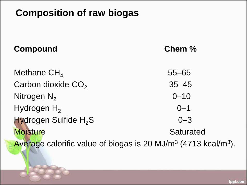
Composition of raw biogas
Compound Chem %
Methane CH4 55–65
Carbon dioxide CO2 35–45
Nitrogen N2 0–10
Hydrogen H2 0–1
Hydrogen Sulfide H2S 0–3
Moisture Saturated
Average calorific value of biogas is 20 MJ/m3 (4713 kcal/m3).
Unlike conventional natural gas which is composed mostly
of hydrocarbons — 70% or more methane (CH4) plus
propane and butane — raw biogas generally contains
somewhat less methane, a significant amount of carbon
dioxide (CO2), and lesser amounts of nitrogen, hydrogen,
carbon monoxide and a variety of contaminants.

Raw Biogas Upgraded Biogas
• A low Grade fuel (CH4 55-65
% & CO2 35-45 %) with lower
percentage of methane.
• Mode of utilisation
– The presence of CO2 besides
being non combustible,
restrains its compressibility
there by making biogas difficult
to be stored in containers.
• A high grade fuel (CH4 > 90 %
and < 10 % other gases) with high
percentage of methane.
• Mode of utilisation
– Remote applications
– Methane burns faster hence
yields a higher specific output
and thermal efficiency compared
to raw biogas when used as
engine fuel.
– Upgrading , compression and
bottling facilitates easy storage
and transportation as a vehicle
fuel
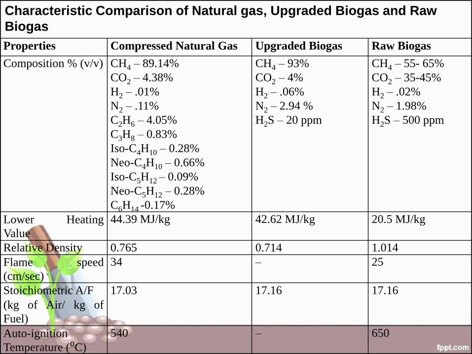
Properties Compressed Natural Gas Upgraded Biogas Raw Biogas
Composition % (v/v) CH4 – 89.14% CO2 – 4.38% H2 – .01% N2 – .11% C2H6 – 4.05% C3H8 – 0.83% Iso-C4H10 – 0.28% Neo-C4H10 – 0.66% Iso-C5H12 – 0.09% Neo-C5H12 – 0.28% C6H14 -0.17%
CH4 – 93% CO2 – 4% H2 – .06% N2 – 2.94 % H2S – 20 ppm
CH4 – 55- 65% CO2 – 35-45% H2 – .02% N2 – 1.98% H2S – 500 ppm
Lower Heating
Value 44.39 MJ/kg 42.62 MJ/kg 20.5 MJ/kg
Relative Density 0.765 0.714 1.014 Flame speed
(cm/sec) 34 – 25
Stoichiometric A/F (kg of Air/ kg of
Fuel)
17.03 17.16 17.16
Auto-ignition
Temperature (⁰C) 540 – 650
Characteristic Comparison of Natural gas, Upgraded Biogas and Raw
Biogas
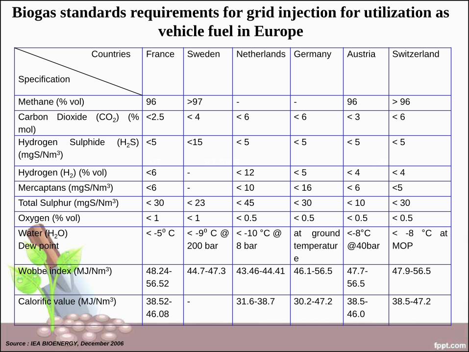
Biogas standards requirements for grid injection for utilization as
vehicle fuel in Europe
97 87-98.5 >97
Source : IEA BIOENERGY, December 2006
Countries
Specification
France Sweden Netherlands Germany Austria Switzerland
Methane (% vol) 96 >97 - - 96 > 96
Carbon Dioxide (CO2) (%
mol)
<2.5 < 4 < 6 < 6 < 3 < 6
Hydrogen Sulphide (H2S)
(mgS/Nm3)
<5 <15 < 5 < 5 < 5 < 5
Hydrogen (H2) (% vol) <6 - < 12 < 5 < 4 < 4
Mercaptans (mgS/Nm3) <6 - < 10 < 16 < 6 <5
Total Sulphur (mgS/Nm3) < 30 < 23 < 45 < 30 < 10 < 30
Oxygen (% vol) < 1 < 1 < 0.5 < 0.5 < 0.5 < 0.5
Water (H2O)
Dew point
< -5⁰ C < -9⁰ C @
200 bar
< -10 °C @
8 bar
at ground
temperatur
e
<-8°C
@40bar
< -8 °C at
MOP
Wobbe index (MJ/Nm3) 48.24-
56.52
44.7-47.3 43.46-44.41 46.1-56.5 47.7-
56.5
47.9-56.5
Calorific value (MJ/Nm3) 38.52-
46.08
- 31.6-38.7 30.2-47.2 38.5-
46.0
38.5-47.2
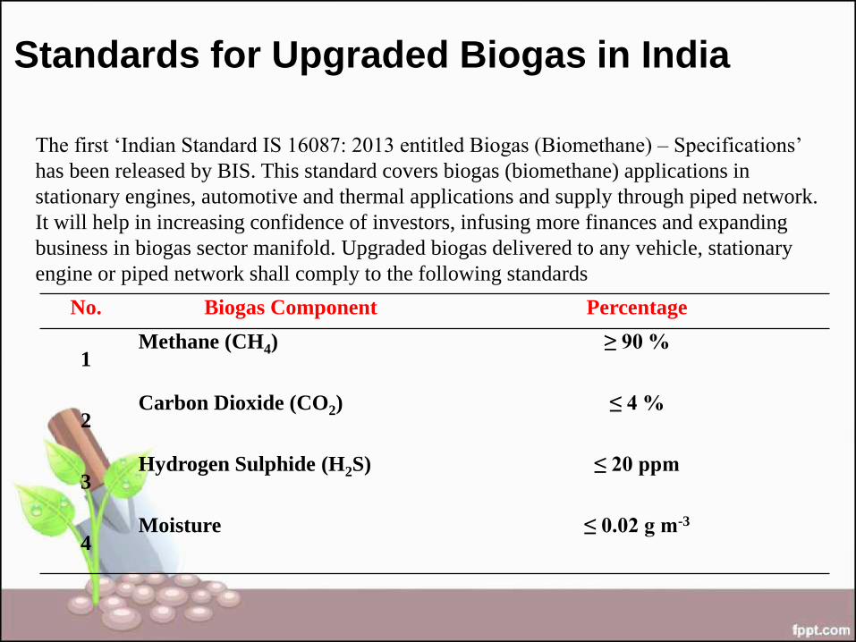
Standards for Upgraded Biogas in India
The first ‘Indian Standard IS 16087: 2013 entitled Biogas (Biomethane) – Specifications’
has been released by BIS. This standard covers biogas (biomethane) applications in
stationary engines, automotive and thermal applications and supply through piped network.
It will help in increasing confidence of investors, infusing more finances and expanding
business in biogas sector manifold. Upgraded biogas delivered to any vehicle, stationary
engine or piped network shall comply to the following standards
No. Biogas Component Percentage
1 Methane (CH4) ≥ 90 %
2 Carbon Dioxide (CO2) ≤ 4 %
3 Hydrogen Sulphide (H2S) ≤ 20 ppm
4 Moisture ≤ 0.02 g m-3
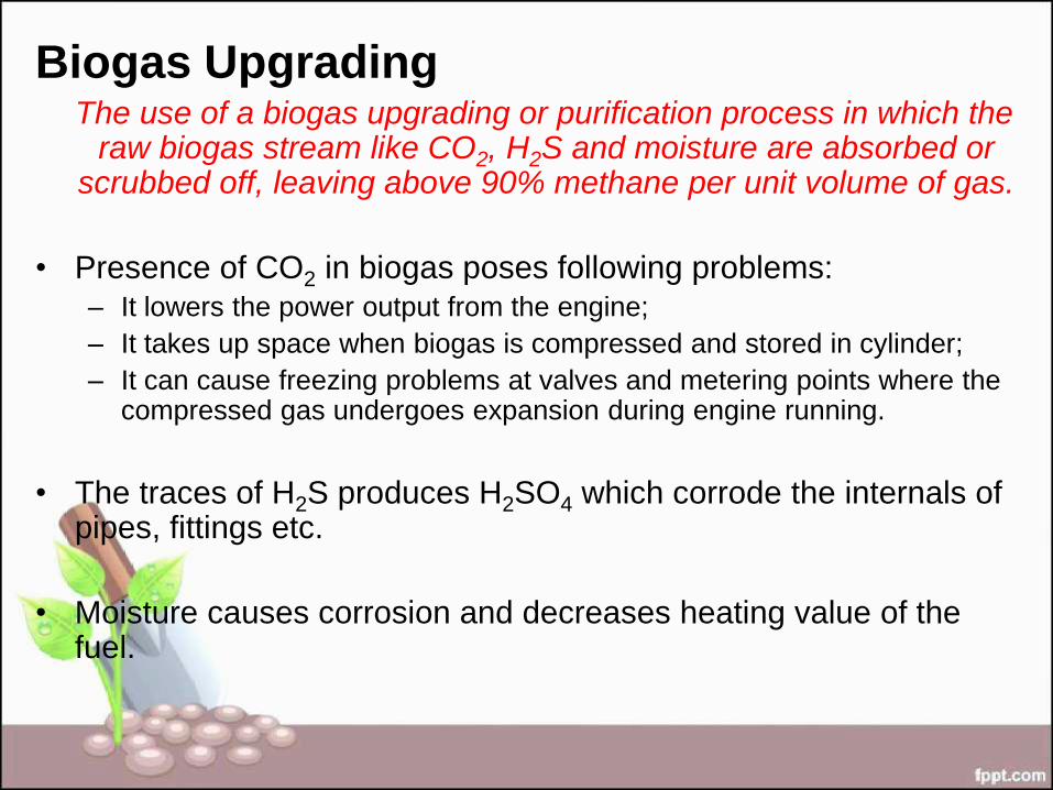
Biogas Upgrading The use of a biogas upgrading or purification process in which the
raw biogas stream like CO2, H2S and moisture are absorbed or scrubbed off, leaving above 90% methane per unit volume of gas.
• Presence of CO2 in biogas poses following problems:
– It lowers the power output from the engine;
– It takes up space when biogas is compressed and stored in cylinder;
– It can cause freezing problems at valves and metering points where the compressed gas undergoes expansion during engine running.
• The traces of H2S produces H2SO4 which corrode the internals of pipes, fittings etc.
• Moisture causes corrosion and decreases heating value of the fuel.

Compression of Biogas
• The energy density of upgraded biogas is comparatively
low at ambient pressure and as a result it must be
compressed at high pressures (e.g. 200-250 bar) to allow
its sufficient storage in bottles/cylinders.
• Compressing biogas
• reduces storage space requirements,
• concentrates energy content and
• increases pressure to the level needed to overcome resistance to
gas flow.
• Compression can eliminate the mismatch of pressures
and guarantee the efficient operation of the equipment.
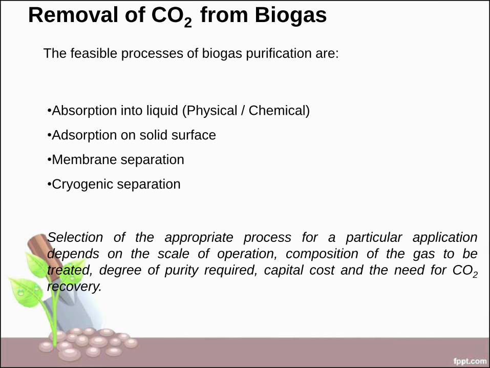
Removal of CO2 from Biogas
The feasible processes of biogas purification are:
•Absorption into liquid (Physical / Chemical)
•Adsorption on solid surface
•Membrane separation
•Cryogenic separation
Selection of the appropriate process for a particular application
depends on the scale of operation, composition of the gas to be
treated, degree of purity required, capital cost and the need for CO2
recovery.

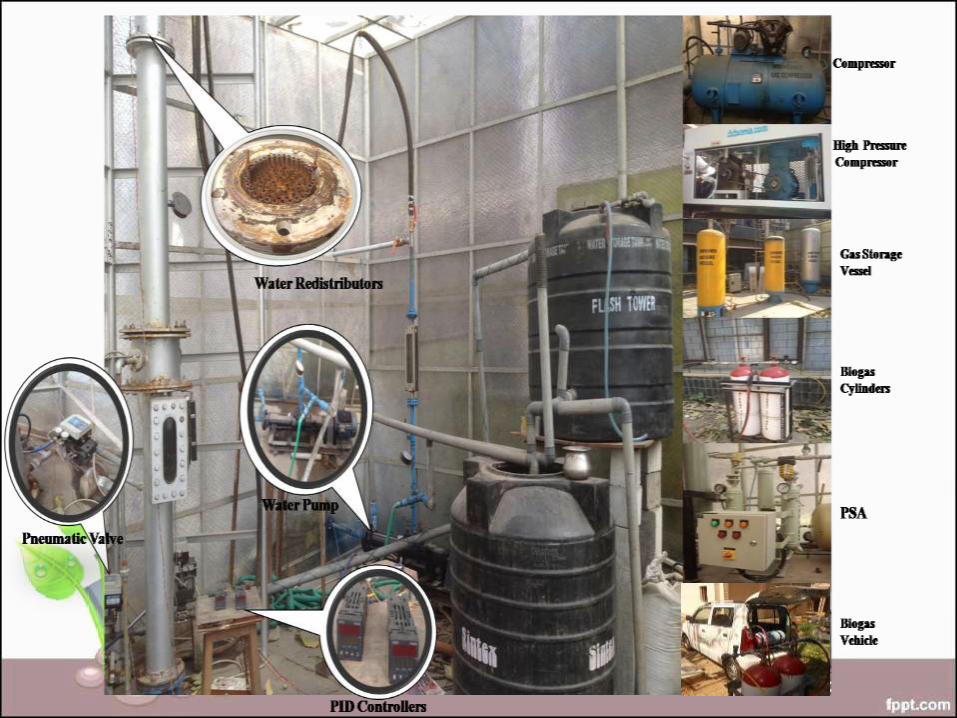
Biogas upgrading using water
scrubbing method at IIT Delhi

Water Scrubbing Method
• Involves the physical absorption of CO2 and H2S in water at high
pressures and regeneration by a release in pressure with very little
change in temperature.
• Easiest and cheapest method involving use of pressurized water as
an absorbent.
• The absorption process is, thus a counter-current one. The dissolved
CO2 and H2S in water are collected at the bottom of the tower.
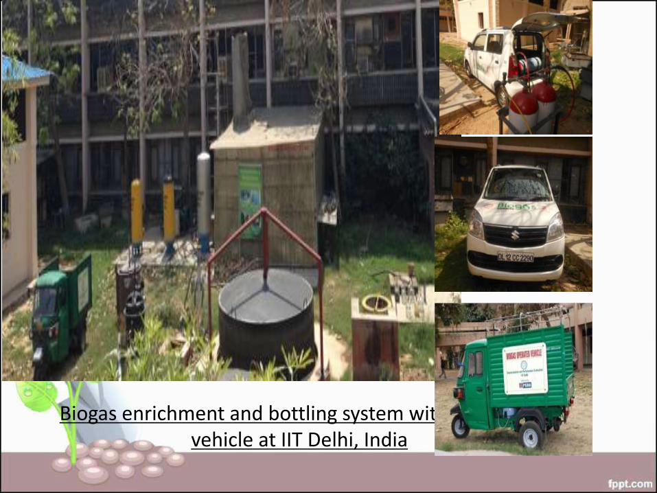
Biogas enrichment and bottling system with biogas vehicle at IIT Delhi, India
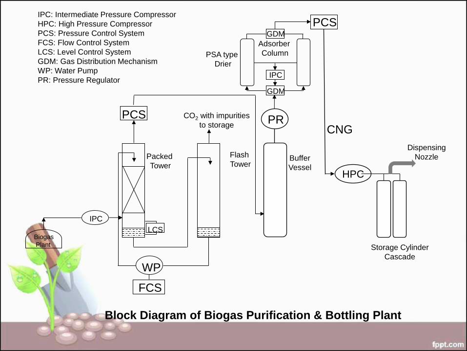
Block Diagram of Biogas Purification & Bottling Plant
IPC: Intermediate Pressure Compressor
HPC: High Pressure Compressor
PCS: Pressure Control System
FCS: Flow Control System
LCS: Level Control System
GDM: Gas Distribution Mechanism
WP: Water Pump
PR: Pressure Regulator
PSA type
Drier
IPC
WP
FCS
LCS
PCS
Biogas
Plant
Packed
Tower
Flash
Tower
GDM
IPC
GDM
Adsorber
Column
PCS
PR
HPC
CNG
Storage Cylinder
Cascade
Dispensing
Nozzle Buffer
Vessel
CO2 with impurities
to storage

A Biogas Bottling plant
Consists of
– High Pressure compressor,
– Cascade of storage cylinders and
– A dispensing nozzle for filling the compressed purified gas in
the vehicles.
Dried and purified gas goes into the suction of High Pressure
Compressor, where it compress the gas to desired working
pressure (~200 Bar) and fill into the storage cylinder
cascade. A CNG dispensing cable along with nozzle is used
for filling of gas in the vehicles.
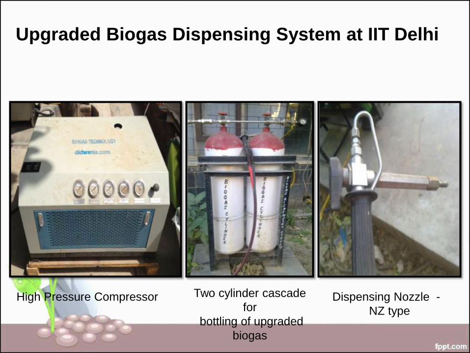
Upgraded Biogas Dispensing System at IIT Delhi
High Pressure Compressor Two cylinder cascade
for
bottling of upgraded
biogas
Dispensing Nozzle -
NZ type


Video

Issues for discussion
• Technology for dissemination – scale,
suppliers,
• Government support – subsidy, incentives
• Policy and regulations – use in
vehicles,LPG replacement, PESO, BIS
• Industry / Green Industry – licensing/land
use, environmental certificates etc

THANK YOU