“biochips ”: micro-fabrication and characterization...
TRANSCRIPT
Version 26/05/09
1
Centre Interuniversitaire de
Microélectronique de Grenoble
“BioChips ”: micro-fabrication and characterization of DNA based-
microarrays on glass
This practical work is organized in two parts that will take place at the Interuniversity Center for
MicroElectronics (CIME), Minatec BCAi, 3 parvis Louis Néel, Grenoble (Tram B: Cité internationale)
Day 1 (4 hrs) – Covalent grafting of DNA probes on silanized glass slides
Day 2 (4hrs) – Hybridization with fluorescently labeled target DNA.
Functional characterization by fluorescence scanning and quantitative image analysis.
This lab work was prepared by Michel Labeau and Jean-Edouard Mendez at Grenoble INP Phelma
with the help of Pierre Barritault, Antoine Huang, David Peyrade and Philippe Pelletier at the
Laboratoire d’Electronique et des Technologies de l’Information at the CEA-Grenoble. It was updated
and put together by Franz Bruckert and Marianne Weidenhaupt (Grenoble INP Phelma).
Version 26/05/09
2
MATERIALS USED
The DNA chip is produced on commercial glass slides from Genewave (http://www.genewave.com/)
specially manufactured for fluorescence based microarray applications.
Amplislide TM
A (Genewave)
All specifications of the glass slides used are given on the product sheet (p.3).
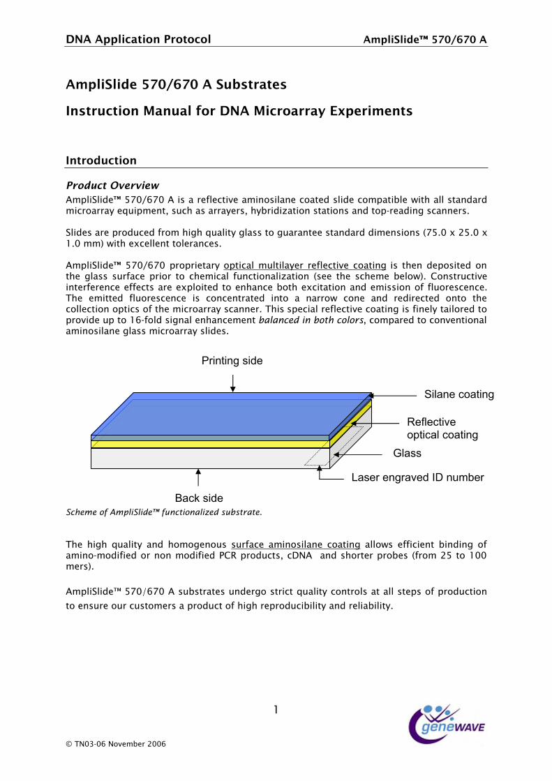
The glass surface is already functionalized with an aminosilane layer that will be used to covalently
attach NH2-DNA probes via a glutalaldehyde linker (see chemistry in Appendix 1).
Amplislides exhibit a unique fluorescence-amplifying, thin film optical coating that allows a 10 to 20
fold signal enhancement.
The fluorescence will be detected using a DNA array scanner:
DNA array Reader (Genewave)
We use a DiagArray™ which is a compact, versatile and intuitive fluorescence microarray reader
designed for fast and accurate readout of slides. All specifications of the scanner are given on the
product sheet (p.7).
Version 26/05/09
3
Day 1:
SPECIFIC COVALENT BONDING OF DNA PROBE MOLECULES ON THE
FUNCTIONALIZED GLASS SLIDES
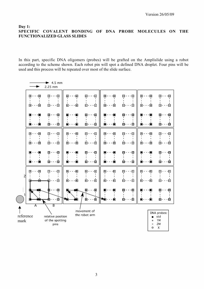
In this part, specific DNA oligomers (probes) will be grafted on the Amplislide using a robot
according to the scheme shown. Each robot pin will spot a defined DNA droplet. Four pins will be
used and this process will be repeated over most of the slide surface.
reference
mark

!"#$#%%&'()*'+,$-.+*+(+&$ $ #/%&'0&'123$4567856$#$
#/%&'0&'12$4567856$#$09:;*.)*2;$
<,;*.9(*'+,$=),9)&$>+.$!"#$='(.+)..)?$@A%2.'/2,*;$
$
<,*.+19(*'+,$
!"#$%&'()*+"*,+-(
!"#$%&$%'()*+,-./,-*!*%0*1*2(3$(45%6(*1"%780%$17(*4815('*0$%'(*48"#15%9$(*:%5;*1$$*0517'12'*"%4281221<*(=>%#"(75?*0>4;*10*1221<(20?*;<92%'%@15%87*0515%870*17'*58#A2(1'%7B*04177(20C**&$%'(0*12(*#28'>4('*328"*;%B;*=>1$%5<*B$100*58*B>12175((*0517'12'*'%"(70%870*D,+C-*E*F+C-*E*GC-*""H*:%5;*(E4($$(75*58$(2174(0C***!"#$%&$%'()*+,-./,-*#28#2%(512<*8#5%41$*">$5%$1<(2* 2(3$(45%6(* 4815%7B* %0* 5;(7*'(#80%5('*87*5;(*B$100* 0>2314(*#2%82* 58* 4;("%41$* 3>745%871$%@15%87* D0((* 5;(* 04;("(*9($8:HC*I87052>45%6(*%75(23(2(74(*(33(450*12(*(E#$8%5('*58*(7;174(*985;*(E4%515%87*17'*("%00%87*83*3$>82(04(74(C*J;(* ("%55('* 3$>82(04(74(* %0* 4874(75215('* %758* 1* 71228:* 487(* 17'* 2('%2(45('* 8758* 5;(*48$$(45%87*8#5%40*83*5;(*"%4281221<*04177(2C*J;%0*0#(4%1$*2(3$(45%6(*4815%7B*%0*3%7($<*51%$82('*58*#286%'(*>#*58*G/A38$'*0%B71$*(7;174("(75*!"#"$%&'()$(!*+,(%*#*-.?*48"#12('*58*4876(75%871$*1"%780%$17(*B$100*"%4281221<*0$%'(0C**
Glass
Reflective optical coating
Silane coating
Laser engraved ID number
Back side
Printing side
/%,&0&(*1(203#)/#)'&4(15$%+)*$"#)6&'(.5!.+-"+&7(
**J;(* ;%B;* =>1$%5<* 17'* ;8"8B(78>0* 0>2314(* 1"%780%$17(* 4815%7B* 1$$8:0* (33%4%(75* 9%7'%7B* 83*1"%78A"8'%3%('*82*787*"8'%3%('*KIL*#28'>450?*4MN!**17'*0;825(2*#289(0*D328"*F+*58*G--*"(20HC**
!"#$%&$%'()*+,-./,-*!*01203453(0*16'(478*034%93*:15$%3;*986348$0*53*5$$*03(#0*8<*#48'193%86*
38*(6014(*814*91038"(40*5*#48'193*8<*=%7=*4(#48'19%2%$%3;*56'*4($%52%$%3;>*
G*
O*JN-PA-/*N86("9(2*F--/* *
!"#$#%%&'()*'+,$-.+*+(+&$ $ #/%&'0&'123$4567856$#$
!"#$%&'(%)*(+%)*,-)&(
!" #$%&'(&')*+,-./01./,#,234,5*,6789*),37,&*367,4'4*,$847:6,37,988$,7*$%*937;9*,<=/,78, =->?@, '4, '76, 89'A'43&, 34), ;4)3$3A*), %32B3A'4A", C7, $;67, 5*, ;6*), %9'89, 78, 7:*,*D%'937'84,)37*,'4)'237*),84,7:*,%32B3A*",,
=" (&')*6,$;67,5*,;6*), '4,3,2&*34,*4E'984$*47, 78,3E8'), 7:*,%9*6*42*,8F,%397'2&*6, 7:37,234,%98E8B*,)*F3;&76,8F,%9'47'4A,89,532BA98;4),48'6*6,G:*4,62344'4A",
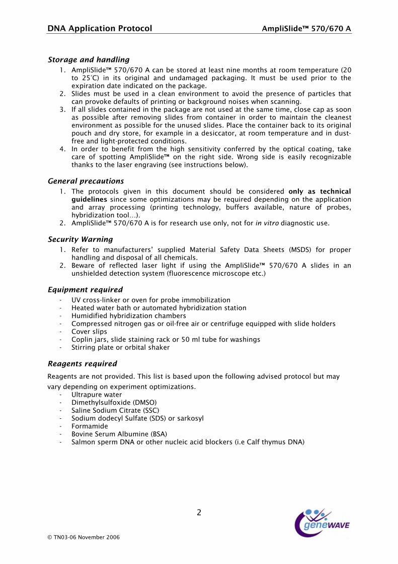
H" CF,3&&,6&')*6,28473'4*),'4,7:*,%32B3A*,39*,487,;6*),37,7:*,63$*,7'$*I,2&86*,23%,36,6884,36, %866'5&*, 3F7*9, 9*$8E'4A, 6&')*6, F98$, 28473'4*9, '4, 89)*9, 78,$3'473'4, 7:*, 2&*34*67,*4E'984$*47,36,%866'5&*,F89,7:*,;4;6*),6&')*6",J&32*,7:*,28473'4*9,532B,78,'76,89'A'43&,%8;2:,34),)9K,6789*I,F89,*D3$%&*,'4,3,)*6'223789I,37,988$,7*$%*937;9*,34),'4,);67LF9**,34),&'A:7L%987*27*),284)'7'846",
M" C4, 89)*9, 78, 5*4*F'7, F98$, 7:*, :'A:, 6*46'7'E'7K, 284F*99*), 5K, 7:*, 8%7'23&, 2837'4AI, 73B*,239*, 8F, 6%877'4A, #$%&'(&')*+, 84, 7:*, 9'A:7, 6')*", N984A, 6')*, '6, *36'&K, 9*28A4'O35&*,7:34B6,78,7:*,&36*9,*4A93E'4A,<6**,'4679;27'846,5*&8G@",
.')'$%,(/$'0%1"-#)2(
!" P:*, %987828&6, A'E*4, '4, 7:'6, )82;$*47, 6:8;&), 5*, 2846')*9*), +,&9$ ):$ *2(;,'()&$<='12&',2:,6'42*,68$*,8%7'$'O37'846,$3K,5*,9*Q;'9*),)*%*4)'4A,84,7:*,3%%&'237'84,34), 3993K, %982*66'4A, <%9'47'4A, 7*2:48&8AKI, 5;FF*96, 3E3'&35&*I, 437;9*, 8F, %985*6I,:K59')'O37'84,788&R@",
=" #$%&'(&')*+,-./01./,#,'6,F89,9*6*392:,;6*,84&KI,487,F89!"#!$"%&',)'3A4867'2,;6*",
!'01$-"3(4%$)-)&(
!" S*F*9, 78, $34;F327;9*96T, 6;%%&'*), U37*9'3&, (3F*7K, V373, (:**76, <U(V(@, F89, %98%*9,:34)&'4A,34),)'6%863&,8F,3&&,2:*$'23&6",
=" W*G39*, 8F, 9*F&*27*), &36*9, &'A:7, 'F, ;6'4A, 7:*, #$%&'(&')*+, -./01./, #, 6&')*6, '4, 34,;46:'*&)*),)*7*27'84,6K67*$,<F&;89*62*42*,$'298628%*,*72"@,
561-/7')"($'61-$'*(
L XY,29866L&'4B*9,89,8E*4,F89,%985*,'$$85'&'O37'84,L Z*37*),G37*9,537:,89,3;78$37*),:K59')'O37'84,6737'84,L Z;$')'F'*),:K59')'O37'84,2:3$5*96,L ?8$%9*66*),4'798A*4,A36,89,8'&LF9**,3'9,89,2*479'F;A*,*Q;'%%*),G'7:,6&')*,:8&)*96,L ?8E*9,6&'%6,L ?8%&'4,[396I,6&')*,673'4'4A,932B,89,-/,$&,7;5*,F89,G36:'4A6,L (7'99'4A,%&37*,89,895'73&,6:3B*9,
8'%&')"2($'61-$'*(
!"#$"%&'(#)"(%*&(+)*,-."./(01-'(2-'&(-'(3#'".(4+*%(&1"(5*22*6-%$(#.,-'".(+)*&*7*2(34&(8#9(
,#)9(."+"%.-%$(*%(":+")-8"%&(*+&-8-;#&-*%'/((L X&793%;9*,G37*9,L V'$*7:K&6;&F8D')*,<VU(\@,L (3&'4*,(8)';$,?'7937*,<((?@,L (8)';$,)8)*2K&,(;&F37*,<(V(@,89,639B86K&,L ]89$3$')*,L W8E'4*,(*9;$,#&5;$'4*,<W(#@,L (3&$84,6%*9$,V^#,89,87:*9,4;2&*'2,32'),5&82B*96,<'"*,?3&F,7:K$;6,V^#@,
=,
_,P^/HL/1,^8E*$5*9,=//1, ,

!"#$#%%&'()*'+,$-.+*+(+&$ $ #/%&'0&'123$4567856$#$
-.',*',9$
!"#$$%&'(#)"*$+,+-+$.'
!"#$%&$%'()*+,-./,-*!*0$%'(0*12(*34"#15%6$(*7%58*1$$*3495135*42*949:3495135*1221;(20<*
/&+0$+01'2+3%'
=9*42'(2*54*6(9(>%5*>24"*58(*8%?8*0(90%5%@%5;*349>(22('*6;*58(*8%?8*5(3894$4?;*4#5%31$*3415%9?A*51B(*312(*4>*0#455%9?*!"#$%&$%'()*49*58(*"%2242('*0%'(<*"+,:;).(+121$ <&'12<=* C8(* 7249?* 0%'(* %0* (10%$;* 2(34?9%D16$(* 5819B0* 54* $10(2* (9?21@%9?<*E$(10(* "1B(* 0F2(* 54* 1221;A* 8;62%'%D(* 19'* 0319* 49$;* 58(* 0F2>13(* >2((* 4>* (9?21@%9?<* C8(*G?(9(71@(G* %9032%#5%49* 19'* H(9(71@(I0* 5213(16%$%5;* =J* 9F"6(2* KLHM-NNO* 49* 58(* #%35F2(*6($47P*084F$'*QRC*6(*@%0%6$(*78(9*;4F*#F5*58(*0$%'(0*4954*58(*0#455(2*521;<*=9*2(3(95*61538(0*58(*%9032%#5%49*L7249?*0%'(O*%0*1''('*>42*(@(9*"42(*(10;*%'(95%>%315%49*K945*08479*6($47P<*
*
* *
!"##$%&'()*##"#$+,'-*+$' .#"/0'(12#$'032--,'-*+$'
>).(+121$<&'12<=*C8(*61234'(*$16($*%0*1##$%('*49*58(*"%2242('*K3422(35P*0%'(<*E$(10(*"1B(*0F2(*54*1221;A*8;62%'%D(*19'*0319*49$;*58(*0F2>13(*7%58*1*61234'(*$16($<*C8(0(*61234'(*$16($0*084F$'*6(*@%0%6$(*78(9*;4F*#F5*58(*0$%'(0*4954*58(*0#455(2*521;<*
*
* *!"##$%&'()*##"#$+,'-*+$' .#"/0'(12#$'032--,'-*+$'
/&+0$+01'*&%*'
C8(*5451$*12(1*1@1%$16$(*>42*#2%95%9?*%0*,-STT*""*>42*0$%'(0*7%584F5*61234'(*19'*/NSTT*""*>42*0$%'(0*7%58*61234'(<*
N*
U*CQ-N:-/*Q4@("6(2*T--/* *

Version 26/05/09
4
Silane activation (see chemical reaction scheme in appendix I)
Aldehydes combine with amines to form Schiff bases, which can be stabilized by oxidation.
Glutaraldehyde is a bifunctional aldehyde that allows covalent coupling between !-aminopropylsilane
at the surface of the glass slide and amino-modified DNA oligomers deposited by the robot pins.
- 1rst
treatment :
When purchased, Amplislides are vacuum sealed. This first treatment is only required when the slide
remained several days in contact with ambient air. CO2 contained in air reacts with terminal NH2 and
forms NH2CO3 , which prevents efficient coupling. This reaction is reversed by KOH treatment.
• Immerse the glass slide in a 0.1 M KOH aqueous solution during 15 min
• Rinse thoroughly with distilled water using the dispenser and dry with compressed air (be careful
not to let the glass slide fly away !)
- 2nd
treatment:
Be careful not to breathe toxic glutaraldehyde fumes. Work in the fume hood, wear gloves
and a labcoat.
• Immerse the glass slide in a 10% glutaraldehyde (Sigma G-7651) aqueous solution and gently
agitate during 45 min at room temperature (rotamax).
• Rinse with distilled water using the dispenser and dry with compressed air.
DNA probe grafting using the MicroGrid robot (BioRobotics)
Four DNA oligomers are used :
- a “standard” sequence : “Std” TTTTTGATAAACCCACTCTA
- a standard sequence with one mismatch: “1M” TTTTTGATAAAGCCACTCTA
- a standard sequence with two mismatches: “2M” TTTTTGATAAAGACACTCTA
- an “unrelated” sequence “X” TTTTTTTTTCCAAGAAAGGACCCG
These oligomers are covalently modified at the 5’-terminus by an amine (Apibio, Grenoble). The
DNA concentration in the stock solution is 200 µM.
Prepare a 50 µL solution of the different probes at 10 µM in 0.3 M sodium phosphate solution and
transfer in the 384-well sample plate of the robot.
The four probes will be spotted onto the glass slide using a robotic arrayer.
The defined parameters of the robot are: the type of sample (silicon wafers or glass plates), the number
of probes, the number of pins used, their type, the spotting velocity, the basic motif and the number of
repeats, the washing procedures. The slide is held on the robot moving plate by vacuum suction. A
reference mark will be drawn near the leftmost bottom spot (A1).
Two types of pins can be used: solid pins and quill pins that deliver 250 µm and 180 µm spots
respectively. We are going to use quill pins.

Version 26/05/09
5
solid pin quill pin
When all parameters have been defined, the spotting procedure is launched. The slides are then
incubated overnight at room temperature in a humid atmosphere.
The next morning, a stabilization treatment is performed by the CIME technical staff.
- NaBH4 reduction of pending aldehyde bonds (CHO " CH2-OH) and N=C stabilization.
- Stringent washing with an anionic detergent (0.2% SDS) to remove the probes that are not covalently
bound to the slide.
The DNA chips are then rinsed with distillated water and dried with compressed air. They can be
stored at 4°C under nitrogen gas and are stable for several months.
Version 26/05/09
6
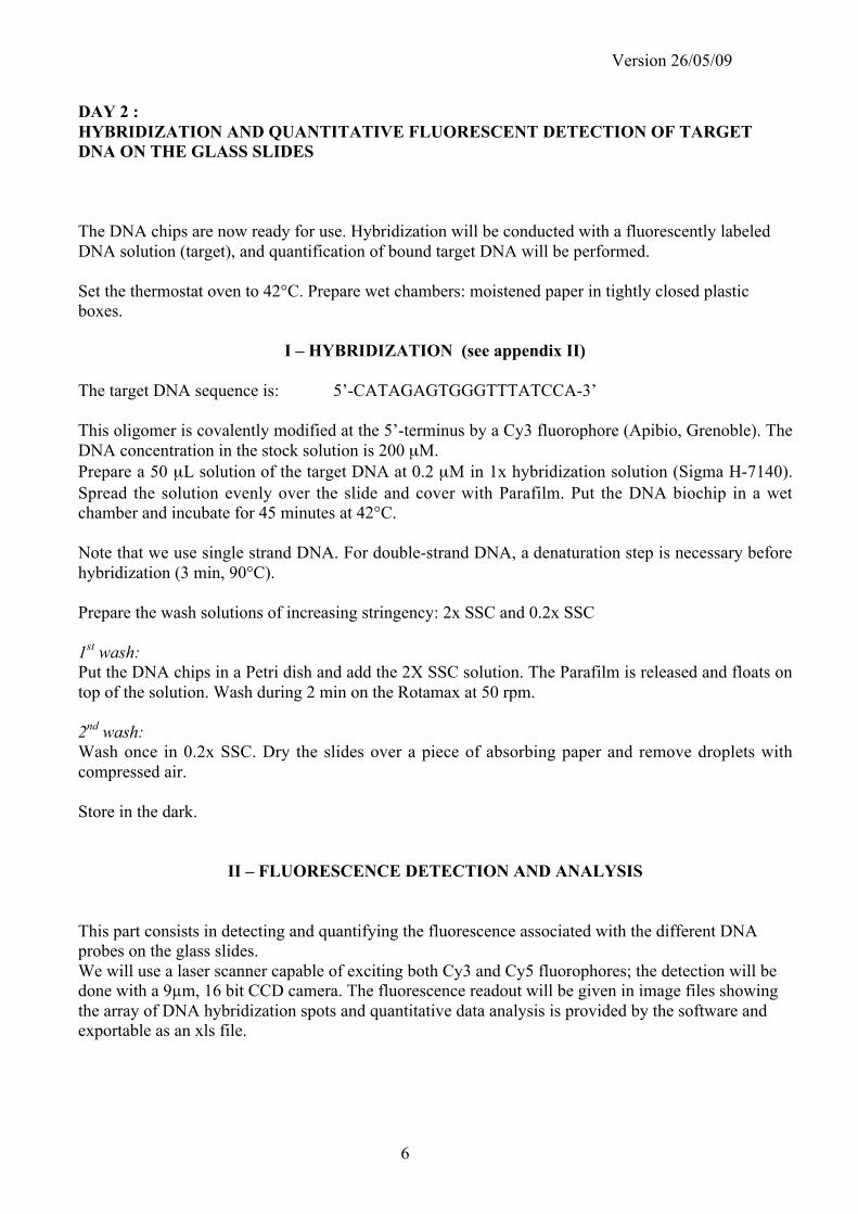
DAY 2 :
HYBRIDIZATION AND QUANTITATIVE FLUORESCENT DETECTION OF TARGET
DNA ON THE GLASS SLIDES
The DNA chips are now ready for use. Hybridization will be conducted with a fluorescently labeled
DNA solution (target), and quantification of bound target DNA will be performed.
Set the thermostat oven to 42°C. Prepare wet chambers: moistened paper in tightly closed plastic
boxes.
I – HYBRIDIZATION (see appendix II)
The target DNA sequence is: 5’-CATAGAGTGGGTTTATCCA-3’
This oligomer is covalently modified at the 5’-terminus by a Cy3 fluorophore (Apibio, Grenoble). The
DNA concentration in the stock solution is 200 µM.
Prepare a 50 µL solution of the target DNA at 0.2 µM in 1x hybridization solution (Sigma H-7140).
Spread the solution evenly over the slide and cover with Parafilm. Put the DNA biochip in a wet
chamber and incubate for 45 minutes at 42°C.
Note that we use single strand DNA. For double-strand DNA, a denaturation step is necessary before
hybridization (3 min, 90°C).
Prepare the wash solutions of increasing stringency: 2x SSC and 0.2x SSC
1st wash:
Put the DNA chips in a Petri dish and add the 2X SSC solution. The Parafilm is released and floats on
top of the solution. Wash during 2 min on the Rotamax at 50 rpm.
2nd
wash:
Wash once in 0.2x SSC. Dry the slides over a piece of absorbing paper and remove droplets with
compressed air.
Store in the dark.
II – FLUORESCENCE DETECTION AND ANALYSIS
This part consists in detecting and quantifying the fluorescence associated with the different DNA
probes on the glass slides.
We will use a laser scanner capable of exciting both Cy3 and Cy5 fluorophores; the detection will be
done with a 9!m, 16 bit CCD camera. The fluorescence readout will be given in image files showing
the array of DNA hybridization spots and quantitative data analysis is provided by the software and
exportable as an xls file.

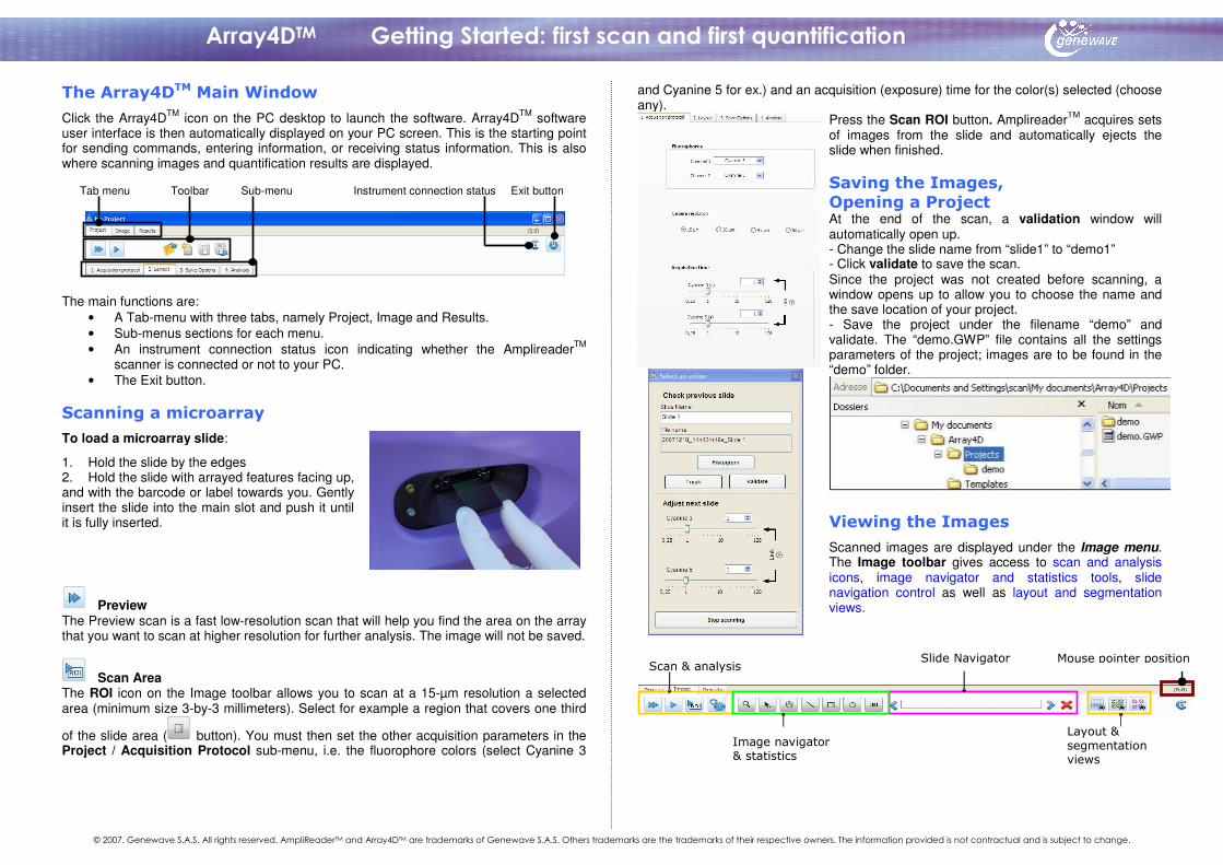
Click the Array4DTM icon on the PC desktop to launch the software. Array4DTM software user interface is then automatically displayed on your PC screen. This is the starting point for sending commands, entering information, or receiving status information. This is also where scanning images and quantification results are displayed.
Tab menu Toolbar Sub-menu Instrument connection status Exit button
The main functions are:
• A Tab-menu with three tabs, namely Project, Image and Results. • Sub-menus sections for each menu. • An instrument connection status icon indicating whether the AmplireaderTM
scanner is connected or not to your PC. • The Exit button.
To load a microarray slide:
1. Hold the slide by the edges 2. Hold the slide with arrayed features facing up, and with the barcode or label towards you. Gently insert the slide into the main slot and push it until it is fully inserted.
Preview The Preview scan is a fast low-resolution scan that will help you find the area on the array that you want to scan at higher resolution for further analysis. The image will not be saved.
Scan Area The ROI icon on the Image toolbar allows you to scan at a 15-µm resolution a selected area (minimum size 3-by-3 millimeters). Select for example a region that covers one third
of the slide area ( button). You must then set the other acquisition parameters in the Project / Acquisition Protocol sub-menu, i.e. the fluorophore colors (select Cyanine 3
and Cyanine 5 for ex.) and an acquisition (exposure) time for the color(s) selected (choose any).
Press the Scan ROI button. AmplireaderTM acquires sets of images from the slide and automatically ejects the slide when finished.
At the end of the scan, a validation window will automatically open up. - Change the slide name from “slide1” to “demo1” - Click validate to save the scan. Since the project was not created before scanning, a window opens up to allow you to choose the name and the save location of your project. - Save the project under the filename “demo” and validate. The “demo.GWP” file contains all the settings parameters of the project; images are to be found in the “demo” folder.
Scanned images are displayed under the Image menu. The Image toolbar gives access to scan and analysis icons, image navigator and statistics tools, slide navigation control as well as layout and segmentation views.
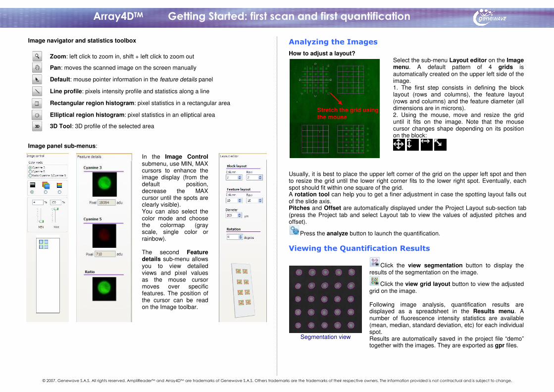
Image navigator and statistics toolbox
Zoom: left click to zoom in, shift + left click to zoom out
Pan: moves the scanned image on the screen manually
Default: mouse pointer information in the feature details panel
Line profile: pixels intensity profile and statistics along a line Rectangular region histogram: pixel statistics in a rectangular area
Elliptical region histogram: pixel statistics in an elliptical area
3D Tool: 3D profile of the selected area
Image panel sub-menus:
In the Image Control submenu, use MIN, MAX cursors to enhance the image display (from the default position, decrease the MAX cursor until the spots are clearly visible). You can also select the color mode and choose the colormap (gray scale, single color or rainbow). The second Feature details sub-menu allows you to view detailed views and pixel values as the mouse cursor moves over specific features. The position of the cursor can be read on the Image toolbar.
How to adjust a layout?
Select the sub-menu Layout editor on the Image menu. A default pattern of 4 grids is automatically created on the upper left side of the image. 1. The first step consists in defining the block layout (rows and columns), the feature layout (rows and columns) and the feature diameter (all dimensions are in microns). 2. Using the mouse, move and resize the grid until it fits on the image. Note that the mouse cursor changes shape depending on its position on the block:
Usually, it is best to place the upper left corner of the grid on the upper left spot and then to resize the grid until the lower right corner fits to the lower right spot. Eventually, each spot should fit within one square of the grid. A rotation tool can help you to get a finer adjustment in case the spotting layout falls out of the slide axis. Pitches and Offset are automatically displayed under the Project Layout sub-section tab (press the Project tab and select Layout tab to view the values of adjustedpitches and offset).
Press the analyze button to launch the quantification.
Segmentation view
Click the view segmentation button to display the results of the segmentation on the image.
Click the view grid layout button to view the adjusted grid on the image. Following image analysis, quantification results are displayed as a spreadsheet in the Results menu. A number of fluorescence intensity statistics are available (mean, median, standard deviation, etc) for each individual spot. Results are automatically saved in the project file “demo” together with the images. They are exported as gpr files.
Stretch the grid using the mouse

Version 26/05/09
7
HYDROXYLATION
!-APS
Si
SiO2
SiSi Si
O
Si
OOH
H2O2/H2SO4Si
SiO2
OH OHOHOH OH
H2O
Si
SiO2
OH OHOHOH OH
H2O
NH2
| (CH2)3
|CH3CH2O#Si#O CH2 CH3
| O CH2 CH3
SILANIZATION
H2O
Si
SiO2
OH OHOHOH OH
H2O
NH2
| (CH2)3
| HO#Si#OH
| OH
Si
SiO2
O
NH2
| (CH2)3
| O#Si#O
| O
HH
O
NH2
| (CH2)3
| O#Si#O
| O
H H
H
H
NH2
| (CH2)3
| O#Si# |
Si
SiO2
O O
NH2
| (CH2)3
| O#Si#O |
Curing
H2O
Atmospheric CO2 INACTIVATION
NH2
| (CH2)3
| O#Si# |
Si
SiO2
O O
NH2
| (CH2)3
| O#Si#O |
CO2
CO2
NH3COO-
| (CH2)3
| O#Si# |
Si
SiO2
O O
NH3COO-
| (CH2)3
| O#Si#O |
RE-ACTIVATION
KOH
NH3COO-
| (CH2)3
| O#Si# |
Si
SiO2
O O
NH3COO-
| (CH2)3
| O#Si#O |
OH- OH-
NH2
| (CH2)3
| O#Si# |
Si
SiO2
O O
NH2
| (CH2)3
| O#Si#O |
OHC(CH2)3COH
NH2
| (CH2)3
| O#Si# |
Si
SiO2
O O
NH2
| (CH2)3
| O#Si#O |
O ||OHC(CH2)3C | H
APPENDIX I :
CHEMICAL COUPLING OF DNA PROBES TO A SILICON
OXIDE SUBSTRATE (OR GLASS)

Version 26/05/09
8
OLIGONUCLEOTIDE GRAFTING
N|
(CH2)3
| O#Si# |
Si
SiO2
O O
N|
(CH2)3
| O#Si#O |
O=C-H | (CH2)3
| CH ||
O=C-H | (CH2)3
| CH ||
L#NH2
N|
(CH2)3
| O#Si# |
Si
SiO2
O O
N|
(CH2)3
| O#Si#O |
O=C-H | (CH2)3
| CH ||
O=C-H | (CH2)3
| CH ||
L#NH2
N|
(CH2)3
| O#Si# |
Si
SiO2
O O
N|
(CH2)3
| O#Si#O |
N || CH | (CH2)3
| CH ||
L$
N || CH | (CH2)3
| CH ||
L$
STABILIZATION TREATMENT
| (CH2)3
| O#Si# |
Si
SiO2
O O
NH NH|
(CH2)3
| O#Si#O
|
N | CH2
| (CH2)3
| CH2
|
L$
-H N-H | CH2
| (CH2)3
| CH2
|
L$
NaBH4
HYBRIDIZATION AND DETECTION
NH|
(CH2)3
| O#Si# |
Si
SiO2
O O
NH|
(CH2)3
| O#Si#O |
N | CH2
| (CH2)3
| CH2
|
L$
H NH | CH2
| (CH2)3
| CH2
|
L$
NH|
(CH2)3
| O#Si# |
Si
SiO2
O O
NH|
(CH2)3
| O#Si#O |
N | CH2
| (CH2)3
| CH2
|
L$
H NH | CH2
| (CH2)3
| CH2
|
L$
Biatine
+
Cy3-
labeled
streptavidin
Cyanine 3
OR
Version 26/05/09
9
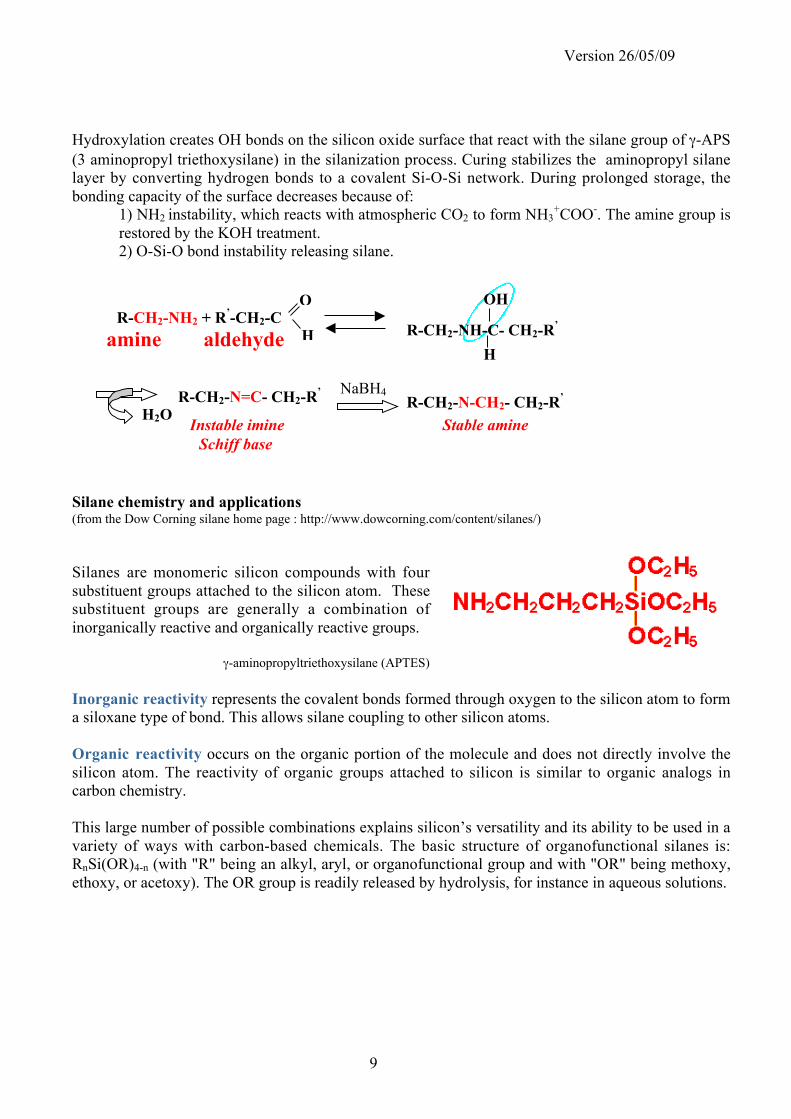
Hydroxylation creates OH bonds on the silicon oxide surface that react with the silane group of !-APS
(3 aminopropyl triethoxysilane) in the silanization process. Curing stabilizes the aminopropyl silane
layer by converting hydrogen bonds to a covalent Si-O-Si network. During prolonged storage, the
bonding capacity of the surface decreases because of:
1) NH2 instability, which reacts with atmospheric CO2 to form NH3+COO
-. The amine group is
restored by the KOH treatment.
2) O-Si-O bond instability releasing silane.
Silane chemistry and applications(from the Dow Corning silane home page : http://www.dowcorning.com/content/silanes/)
Silanes are monomeric silicon compounds with four
substituent groups attached to the silicon atom. These
substituent groups are generally a combination of
inorganically reactive and organically reactive groups.
!-aminopropyltriethoxysilane (APTES)
Inorganic reactivity represents the covalent bonds formed through oxygen to the silicon atom to form
a siloxane type of bond. This allows silane coupling to other silicon atoms.
Organic reactivity occurs on the organic portion of the molecule and does not directly involve the
silicon atom. The reactivity of organic groups attached to silicon is similar to organic analogs in
carbon chemistry.
This large number of possible combinations explains silicon’s versatility and its ability to be used in a
variety of ways with carbon-based chemicals. The basic structure of organofunctional silanes is:
RnSi(OR)4-n (with "R" being an alkyl, aryl, or organofunctional group and with "OR" being methoxy,
ethoxy, or acetoxy). The OR group is readily released by hydrolysis, for instance in aqueous solutions.
H
O
R-CH2-NH-C- CH2-R’
OH
H
H2OR-CH2-N=C- CH2-R
’
Instable imine
NaBH4
R-CH2-N-CH2- CH2-R’
Stable amine
R-CH2-NH2 + R’-CH2-C
amine aldehyde
Schiff base
Version 26/05/09
10
The strands of DNA molecules are held by non-covalent interactions, which are disrupted by
modifying the physico-chemical conditions (denaturation). This process is fully reversible
(renaturation). Considering a given DNA single strand, nucleic acid strands of any origin are able to
associate with it, provided that some complementarity exists between the two molecules: this interaction
is called hybridization.
Many molecular techniques rely on nucleic acid hybridization: polymerase chain reaction (PCR),
electrophoresis and gel blotting techniques (Southern and Northern blots), microscopy localization of
genes on entire chromosomes (FISH) etc …
Essentially, DNA biochips are developed for four purposes:
- Analysis of single gene allele variations in individuals, to help defining molecular medical techniques.
- Species identification (for instance pathogens).
- Gene expression studies, to determine gene usage as a function of the cell, organism, population
environmental conditions.
- Gene editing studies, to measure the expression of mRNA alternative splice variants.
PRINCIPLES OF HYBRIDIZATION :
DNA molecules can be hybridized to other DNA or RNA molecules. DNA is generally double
strand and RNA single strand. In DNA chips, probes are either large DNA molecules such as PCR
products, or small short single strand sequences obtained by chemical synthesis called oligomers. The
nucleic acids to be tested (target) usually are DNA fragments, a DNA copy of expressed RNA (cDNA)
or RNA. The target molecules are generally fluorescently labeled, since direct detection of DNA
hybridization is so far not efficient enough to analyze tiny DNA amounts.
The molecular basis of this association is the formation of hydrogen bonds between
complementary bases A and T, C and G. In addition, the two strands should run in opposite directions
(5’! 3’ ends). Since A::T and G:::C pairing involves 2 and 3 hydrogen bonds respectively, the stability
of nucleic acid complexes depends on the GC content of the sequence involved in their binding. It should
be noted that the association between two nucleic acid molecules does not require perfect
complementarity and the presence of mismatches simply decreases the total binding energy.
The presence of similar gene products in genomes or of different gene alleles in populations
makes it necessary to discriminate between close sequences. Therefore, the physico-chemical conditions
of the hybridization (hybridization stringency) need to be adjusted to render the assay sensitive enough,
ultimately allowing single base differences.
APPENDIX I: HYBRIDIZATION
Version 26/05/09
11
CONTROL OF HYBRIDIZATION STRINGENCY :
Three parameters need to be taken into consideration in hybridization experiments:
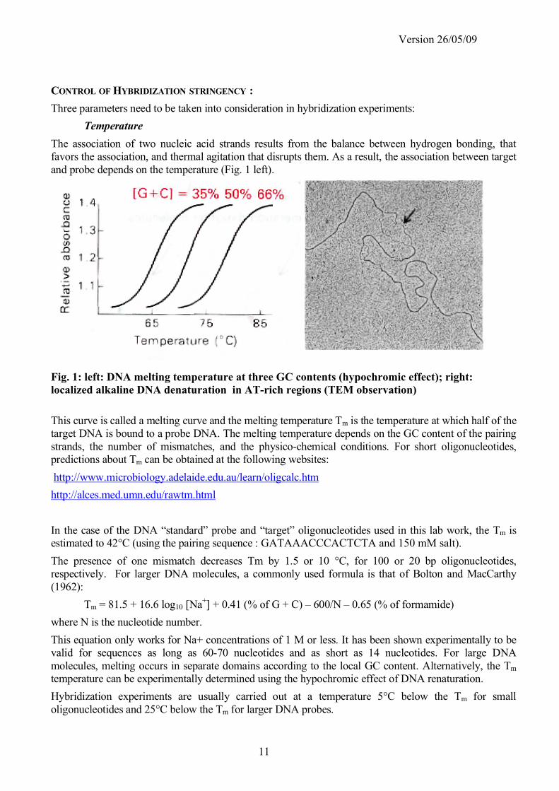
Temperature
The association of two nucleic acid strands results from the balance between hydrogen bonding, that
favors the association, and thermal agitation that disrupts them. As a result, the association between target
and probe depends on the temperature (Fig. 1 left).
Fig. 1: left: DNA melting temperature at three GC contents (hypochromic effect); right:
localized alkaline DNA denaturation in AT-rich regions (TEM observation)
This curve is called a melting curve and the melting temperature Tm is the temperature at which half of the
target DNA is bound to a probe DNA. The melting temperature depends on the GC content of the pairing
strands, the number of mismatches, and the physico-chemical conditions. For short oligonucleotides,
predictions about Tm can be obtained at the following websites:
http://www.microbiology.adelaide.edu.au/learn/oligcalc.htm
http://alces.med.umn.edu/rawtm.html
In the case of the DNA “standard” probe and “target” oligonucleotides used in this lab work, the Tm is
estimated to 42°C (using the pairing sequence : GATAAACCCACTCTA and 150 mM salt).
The presence of one mismatch decreases Tm by 1.5 or 10 °C, for 100 or 20 bp oligonucleotides,
respectively. For larger DNA molecules, a commonly used formula is that of Bolton and MacCarthy
(1962):
Tm = 81.5 + 16.6 log10 [Na+] + 0.41 (% of G + C) – 600/N – 0.65 (% of formamide)
where N is the nucleotide number.
This equation only works for Na+ concentrations of 1 M or less. It has been shown experimentally to be
valid for sequences as long as 60-70 nucleotides and as short as 14 nucleotides. For large DNA
molecules, melting occurs in separate domains according to the local GC content. Alternatively, the Tm
temperature can be experimentally determined using the hypochromic effect of DNA renaturation.
Hybridization experiments are usually carried out at a temperature 5°C below the Tm for small
oligonucleotides and 25°C below the Tm for larger DNA probes.

Version 26/05/09
12
Physico-chemical conditions
Various parameters influence strand pairing.
pH: under alkaline conditions, the phosphate groups on the DNA strand backbone are charged, resulting
in strand separation. Note that alkaline denaturation is not used for RNA molecules, since this also favors
hydrolysis of the phosphodiester bonds along the strand.
Ion concentration (ionic strength): at neutral pH, negative charges are present on the phosphate groups
along the DNA strand backbone. The concentration of counter-ions in the solution therefore modulates
the electrostatic repulsion between DNA strands.
Hydrophobic interaction: during pairing, DNA bases stack together, and some binding energy is gained
through the interaction between the %-electrons of the pyrimidine and purine rings. This creates a
somehow hydrophobic environment, where non-polar molecules can accumulate. Conversely, addition of
detergents weakens the stability of DNA pairing.
Denaturating agents: when using mRNA or cDNA targets, formamide is often used as denaturing agent
since it allows lowering temperature without losing specificity. Furthermore, 50% or greater formamide
favor DNA-RNA hybridization over DNA-DNA hybridization.
High molecular weight polymers (Ficoll, PVP): during hybridization, they increase the effective nucleic
acid concentration by excluding volume from the hybridization mixture.
Concentration and time
It should be noted that DNA hybridization is essentially a non-equilibrium technique. These techniques
use very small amounts of probe and target molecules. Furthermore, probes are immobilized on a
substrate and the bulk target DNA concentration is generally much lower than the local probe
concentration. Thus, one difficult point is to put target DNA in contact with probe DNA molecules.
Experimentally, after denaturation, target DNA is incubated on DNA chips for a relatively long time, at a
temperature lower than the Tm and at rather low stringency, in order to favor the association between
target and probes. Then, washings are performed rapidly, at room temperature, in more stringent
conditions, in order to remove loosely bound molecules while keeping as much as possible specific target-
probe interaction intact. Longer washing times will increase the specificity, but at the expense of a
decrease in fluorescent signal. This explaines why washing procedures are explained in details.
DETECTION OF HYBRIDIZATION :
When labeled DNA or RNA is used, the fluorescence intensity is scanned over each spot. The same
DNA sequence is immobilized on several spots (usually 3), in order to determine statistical variations.
For quantification of gene expression, each gene sequence is represented by different oligonucleotide
sequences, in order to discriminate between similar sequences (overrepresentation). Therefore, most
DNA chips display more than 100 different spots, up to 20000. Data representation and handling
becomes then a major issue in the efficient use of the technique.
Version 26/05/09
13
COMPOSITION OF STANDARD HYBRIDIZATION AND WASHING SOLUTIONS :
Control of the pH and ionic conditions is usually achieved by using a dilution of a concentrated stock,
such as the 20 x SSC or 20 x SSPE solution:
20 x SSC (Sodium Salt Citrate) 20 x SSPE (Soldium Salt Phosphate EDTA)
for 1 Liter for 1 Liter
175.3 g sodium chloride 175.3 g sodium chloride
88.2 g sodium citrate 27.6 g NaH2PO4-H20
adjust the to pH 7.0 with NaOH 7.4 g EGTA
sterilize adjust the to pH 7.0 with NaOH
1x SSC is 0.15 M NaCl and 0.015 M sodium citrate sterilize
at pH 7.2-7.4
Prevention of DNA non-specific binding to surfaces (such as plastics, glass, or silicon) and
acceleration of hybridization by excluded volume effect is achieved by adding a polymer solution
called the Denhardt’s reagent and an excess of an unlabeled DNA solution (usually denaturated
fragmented salmon or herring sperm DNA)
Denhardt’s reagent
For 1 Liter
10 g Ficoll (type 400)
10 g polyvinylpyrrolidone
10 g Bovine Serum Albumin (fraction V)
Filter sterilize
Hybridization solutions are made by diluting an unlabeled DNA solution in 5x to 6x SSC or SSPE and
1x to 5 x Denhardt’s solutions. The composition of the hybridization solution used in the lab work is
given:
Sigma H-7140 hybridization solution (1 x)
100 µg/mL DNA
5 x SSC
1 x Denhardt’s
Filter to 0.2 µm
Here are two examples of washing conditions:
Example 1 Example 2
2 x SSC, SDS 0.1% 5 min x 2 2 x SSC, 2 min
2 x SSC, 5 min x 2 0.2 x SSC, 2 min
Version 26/05/09
14
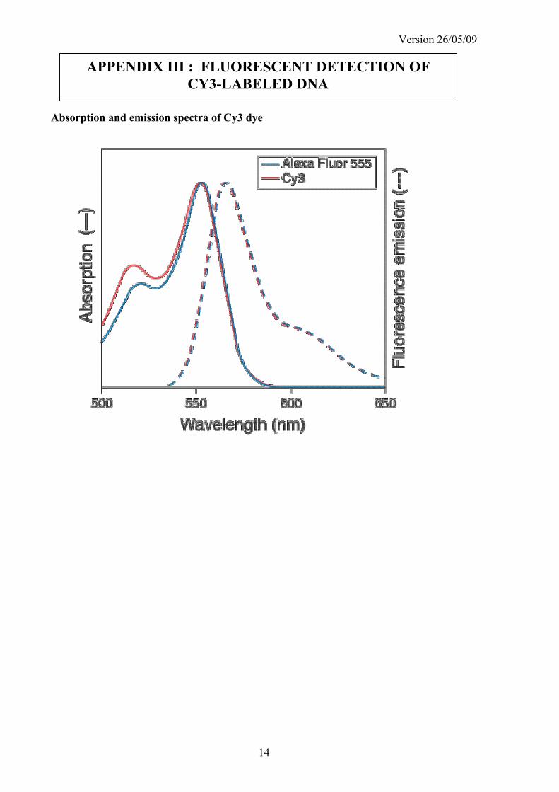
Absorption and emission spectra of Cy3 dye
APPENDIX III : FLUORESCENT DETECTION OF
CY3-LABELED DNA
Version 27/05/09
25
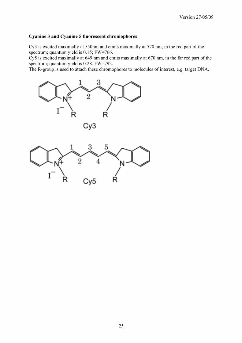
Cyanine 3 and Cyanine 5 fluorescent chromophores
Cy3 is excited maximally at 550nm and emits maximally at 570 nm, in the red part of the
spectrum; quantum yield is 0.15; FW=766.
Cy5 is excited maximally at 649 nm and emits maximally at 670 nm, in the far red part of the
spectrum; quantum yield is 0.28. FW=792.
The R-group is used to attach these chromophores to molecules of interest, e.g. target DNA.

Version 26/05/09
15
The production and use of a DNA biochip involves multiple steps. In order to track down flaws
in the operating procedures, it is advisable to note any changes made to the written protocol or
any observations made. Please note here:
TRACKING SHEET