biocat – clean air technology for small-scale combustion
TRANSCRIPT

BioCAT – Clean air technology for small-scale combustion systems
Gabriel REICHERT, Marius WÖHLER, Manuel SCHWABL, Christoph SCHMIDL,
Stefan AIGENBAUER, Hans BACHMAIER, Franz FIGL, Hans HARTMANN, Walter
HASLINGER, Jens KIRCHHOF, Harald STRESSLER, Rita STURMLECHNER,
Peter TUROWSKI, Bernhard VOGLAUER
Central-European Biomass Conference
January 2014, Graz, Austria

Content
■ Objectives
■ Concept and Approach
■ Methods
■ Results
■ Catalytic material characterisation
■ Catalyst system outside the stove
■ Primary optimisation of stoves
■ Catalyst system integrated in optimised stoves
■ DemoCAT – Catalyst technology demonstrator
■ Conclusions and Outlook
CEBC2014, Graz, 16. January 2014
Slide 2

Project objectives
New generation of biomass based room heating appliances
Optimising primary combustion conditions
Integration of a honeycombtype oxidation catalyst
CEBC2014, Graz, 16. January 2014
Slide 3

The BioCAT project approach
Characterise the catalyst technology
Develop methods to evaluate the project outcomes
Primary optimise combustion systems and integrate catalysts
Evaluate and demonstrate the project outcomes
+1
CEBC2014, Graz, 16. January 2014
Slide 4

Method I: Characterisation of catalytic material
■ Test Setup:
■ Synthetic flue gas:
– CO, CH4, C7H8
■ Pre-heating and mixing zone
■ Flue gas measurement up-
and downstream of catalyst
■ Connection to stove for TSP
loading
■ Results:
■ Basic catalytic performance
characteristics
CEBC2014, Graz, 16. January 2014
Slide 5

Method II: Characterisation of catalyst (standalone/retrofit)
■ Principle:
■ Test Setup:
■ Wood chip burner for flue
gas „production“
■ Boiler with by-pass for flue
gas temperature control
■ Fuel (water content) and
burner settings for flue gas
composition control
■ Results:
■ Actual and mean reduction
of CO, OGC and TSPSource: TFZ Straubing
CEBC2014, Graz, 16. January 2014
Slide 6

Method III: Characterisation of Stove-integrated catalysts
■ Principle:
■ Test setup:
■ EN13240/13229
■ Test Fuels: Beech and Spruce
■ Tests with uncoated Carrier (Dummy, n=6) and with
Catalyst (n=6) for each stove
■ Results:
■ Mean Reduction of CO, OGC and TSP
■ Significant Reduction at defined Level of Confidence
CEBC2014, Graz, 16. January 2014
Slide 7
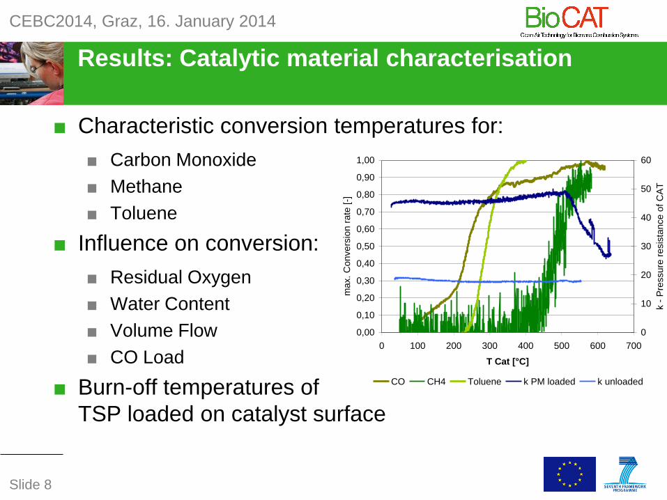
Results: Catalytic material characterisation
■ Characteristic conversion temperatures for:
■ Carbon Monoxide
■ Methane
■ Toluene
■ Influence on conversion:
■ Residual Oxygen
■ Water Content
■ Volume Flow
■ CO Load
■ Burn-off temperatures of
TSP loaded on catalyst surface
0,00
0,10
0,20
0,30
0,40
0,50
0,60
0,70
0,80
0,90
1,00
0 100 200 300 400 500 600 700
T Cat [°C]
ma
x.
Co
nve
rsio
n r
ate
[-]
0
10
20
30
40
50
60
k -
Pre
ssu
re r
esis
tan
ce
of
CA
T
[Pa
/ (m
/s)^
0,7
5]
CO CH4 Toluene k PM loaded k unloaded
CEBC2014, Graz, 16. January 2014
Slide 8

Results: Catalyst EvaluationStandalone/Retrofit Cat
■ Simultaneous
Measurements
■ Mean Reduction Rates:
■ CO: 80%
■ OGC: 48%
■ TSP: 27%
CEBC2014, Graz, 16. January 2014
Slide 9

Results: Combustion system developmentCombustion optimisation by primary measures
■ Avoidance of leakages (air
tightness)
■ Adapting air supply volume
■ Implementing air staging
■ Optimisation of pane
ventilation
■ Insulation of combustion
chamber
■ Implementation of post
combustion chamber
■ Energy management of firebed
Stove A B C D
Initial stoves – Optimized stoves - Test fuel spruce
CO - 74 % - 63 % - 56 % - 44 %
OGC - 72 % - 40 % - 78 % - 47 %
TSP n.a. n.a. - 38 % - 40 %
η + 59 % + 7 % + 34 % ± 0 %
CEBC2014, Graz, 16. January 2014
Slide 10

Results: Combustion system developmentPrimary combustion optimisation
Initial stove Primary optimized stove
■ Extension of optimum (low emission) phase
■ Still need for improvement in start and burn-out phase
CEBC2014, Graz, 16. January 2014
Slide 11

Results: Integration of CatalystPositioning according to measured Operation Characteristics
■ Sufficient high temperature ■ Accessible for maintenance
CEBC2014, Graz, 16. January 2014
Slide 12

Results: Evaluation integrated CatalystReduction of Catalyst vs. Dummy
Reduction
in %*
Mean Significant
(85% confid.)
CO 74-97 64-77
OGC 32-73 0-32
TSP 0-59 0-21
* Test fuel: Spruce
CEBC2014, Graz, 16. January 2014
Slide 13

Results: Combustion System DevelopmentFinal Evaluation of Cat-integrated Stoves
Stove A B C D
Advanced prototype – without catalyst: Test fuel beech
CO (mg/Nm³) 823 1109 825 1003
OGC (mg/Nm³) 48 43 62 64
TSP (mg/Nm³) 106 31 26 21
η (%) 74 81 80 76
Optimized stoves – with catalyst: Test fuel beech
CO (mg/Nm³) 267 200 64 184
OGC (mg/Nm³) n.a. 37 51 47
TSP (mg/Nm³) n.a. 14 8 22
η (%) 74 83 80 81
CEBC2014, Graz, 16. January 2014
Slide 14

Results: DemoCAT – modified Briquette StoveParallel measurement of coated and non-coated catalysts
CAT Dummy Differenz
[%rel]
CO [mg/Nm3]13%O2 116 1.631 -93
O2 [%] 12.3 12.6
T [°C] 581 585
p [pa] 16 (+/-1) 18 (+/-1)
CEBC2014, Graz, 16. January 2014
Slide 15

Summary and Conclusions
■ Primary optimisation of firewood stoves has
shown high potential
■ Reduction ~ 40-80% for CO, OGC, TSP
■ Significant increase of efficiency
■ Catalysts can further reduce emissions
especially in start and burn-out phase
■ 80-90% CO, 40-70% OGC, 0-50% TSP
■ Integration has important advantages
compared to retrofit solutions
■ Higher temperatures
■ Primary effects of catalyst are considered
■ Catalyst integrated prototypes perform
close to pellet stoves in terms of emissions
CEBC2014, Graz, 16. January 2014
Slide 16

Outlook
■ Long-term testing of catalyst integrated stoves
■ Deactivation of catalyst
– Reactivation measures (washing)
– Time interval for replacement
■ Influence of different use patterns
– Safety aspects (blogging of catalysts in case of
maloperation?)
■ BioCAT Demonstrator 2.0
■ Operated with firewood
■ Including TSP measurement section
CEBC2014, Graz, 16. January 2014
Slide 17

Acknowledgements
Company Partners:
Scientific and supporting Partners:
Funding:
The research leading to these results has received funding from the
European Union Seventh Framework Program (FP7/2007-2013) under
Grant Agreement n° 286978.
CEBC2014, Graz, 16. January 2014
Slide 18

BioCATClean Air Technology for Biomass Combustion Systems
Thank you very much for your attention
Christoph Schmidl
CEBC2014, Graz, 16. January 2014
Slide 19

Supplemental Material
CEBC2014, Graz, 16. January 2014
Folie 20

Measurement section catalyst evaluation
CEBC2014, Graz, 16. January 2014
Slide 21

0%
10%
20%
30%
40%
50%
60%
70%
80%
90%
100%
0 0,5 1 1,5 2
CO
co
nv
ers
ion
rate
[%
]
gas velocity [m/s]
0%
10%
20%
30%
40%
50%
60%
70%
80%
90%
100%
0% 5% 10% 15% 20%
CO
co
nv
ers
ion
rate
[%
]
oxygen content [vol%]
Catalyst characterisationInfluence analysis on conversion rate
0%
10%
20%
30%
40%
50%
60%
70%
80%
90%
100%
0% 2% 4% 6% 8% 10%
CO
co
nv
ers
ion
rate
[%
]
water content [vol%]
0%
10%
20%
30%
40%
50%
60%
70%
80%
90%
100%
0 1000 2000 3000 4000 5000
CO
co
nv
ers
ion
rate
[%
]
CO concentration [ppm]
CEBC2014, Graz, 16. January 2014
Slide 22

Results: Combustion system developmentTemperature profiles of optimised stoves
■ Temperature
Profiles of
potential
integration
positions:
■ Basis for the
integration
of catalysts
CEBC2014, Graz, 16. January 2014
Slide 23