bind: binary integrated net descriptors for texture...
TRANSCRIPT

BIND: Binary Integrated Net Descriptors for Texture-less Object Recognition
Jacob Chan1, Jimmy Addison Lee2 and Qian Kemao1
1School of Computer Engineering (SCE), Nanyang Technological UniversityBlock N4 Nanyang Avenue, Singapore [email protected], [email protected]
2Institute for Infocomm Research (I2R), Agency for Science, Technology and Research (A*STAR)1 Fusionopolis Way, Connexis (South Tower), Singapore 138632
Abstract
This paper presents BIND (Binary Integrated NetDescriptor), a texture-less object detector that encodesmulti-layered binary-represented nets for high precisionedge-based description. Our proposed concept aligns layersof object-sized patches (nets) onto highly fragmentedocclusion resistant line-segment midpoints (linelets) toencode regional information into efficient binary strings.These lightweight nets encourage discriminative objectdescription through their high-spatial resolution, enablinghighly precise encoding of the object’s edges and internaltexture-less information. BIND achieved various invariantproperties such as rotation, scale and edge-polarity throughits unique binary logical-operated encoding and matchingtechniques, while performing remarkably well in occlusionand clutter. Apart from yielding efficient computationalperformance, BIND also attained remarkable recognitionrates surpassing recent state-of-the-art texture-less objectdetectors such as BORDER, BOLD and LINE2D.
1. Introduction
Texture-less objects are a familiar sight in the realworld and yet, widely established recognition algorithmssuch as SIFT (Scale Invariant Feature Transform) [1],and SURF (Speeded Up Robust Features) [2] are largelyineffective in such instances. This is due to their heavyreliance on highly-textured, feature-rich informative localregions, which are relatively scarce in homogeneousoccurrences. Therefore, this challenging problem has ledto various recent works such as [3–5], where object-sizedregional information is exploited to gather discriminativecontent. Although producing decent results, extensiveuse of such sizable spatial architecture often leads toexpensive computational run-times as well as memory load.As modern contemporary technologies such as real-timedetection systems and mobile applications have limitedcomputational resources, there is a growing consensus for
Fig. 1: BIND’s texture-less object recognition in high clutterand semi-occlusion. (Top) keypoint matches, (bottom) binary netmatches where green boxes represent angular block matches,yellow boxes indicate internal homogeneous block matches, andgray boxes refers to the background/no-match blocks.
today’s algorithms to be robust, fast and compact.A proven way to produce quick and memory efficient
detectors without hardware acceleration is by means ofbinary descriptors. Works such as BRIEF (Binary RobustIndependent Elementary Features) [6] and ORB (OrientFAST and Rotated BRIEF) [7] utilize local patches forsimple binary intensity tests between pixels to formtheir descriptors. This led to very efficient vector sizesand matching speeds, as these strings can be quicklycompared using the Hamming distance. However, thesebinary descriptors share the same predicament as theaforementioned algorithms, as they similarly require richlocal information for their intensity tests.
Therefore, in pursuit of a texture-less detector thatcaters to the needs of modern technologies, we proposeBIND (Binary Integrated Net Descriptor), a detector
2068

that describes in homogeneous conditions over largeobject-sized regions using uniquely designed multi-layeredbinary nets. BIND adopts a keypoint-descriptor structureby first forming interest points with Linelets [3], arecently introduced highly occlusion-resistant line-segmentdetector, followed by overlaying of our proprietary binarynet-layers, oriented according to each linelet midpoint forencoding various regional characteristics of the object.Nets are essentially large object-encompassing squarepatches that are divided equally into high-resolutionbit-representing blocks. Upon keypoint alignment, theytransform into n net-layers to represent n-bit datawith each internal block embedding information suchas rotation-invariant angle primitives, along with thestructural positioning of the object’s edges and internalhomogeneous space. BIND also addresses the problemof background contrast, whereby line-gradient directionsvary in polarity due to diverse backdrops in the scene,which affects line/orientation edge-based descriptors suchas [3, 4, 8]. Finally, matching is conducted through aseries of binary arithmetic instructions, while incorporatingvarious techniques to include enhancement properties suchas scale invariance and occlusion resistance. In all, BIND’slightweight description technique not only yields efficientcomputational performance, but also delivers exceptionalrecognition competence in clutter and occlusion through itsability to isolate and sample regional object information athigh spatial resolutions. Fig. 1 exhibits BIND’s texture-lessobject recognition capability in a challenging scene.
The rest of the paper is presented as follows. Section 2reviews related texture-less based works. Sections 3 and 4describe the elements of BIND and its encoding schemesrespectively. Section 5 summarizes the overall objectrecognition pipeline. Section 6 exhibits the comparativeexperimental results. Finally, section 7 concludes the paper.
2. Related Work
Although countless object detectors have been proposed,very few can claim to robustly detect texture-less objects.Thus, this section reviews various techniques that hadsignificant contributions to the texture-less genre.
Template-Based Detectors One pioneering approachthat has the capacity to detect texture-less objects isChamfer Matching [9, 10]. It is essentially an edge-basedtemplate matcher where detected contours between themodel and scene are compared through a distance transformbased dissimilarity measure. However, it is plagued withissues such as noise sensitivity and other occlusion factors.This raised several chamfer related enhancements suchas shape-based [11], gradient-directional based [12, 13],and the Hausdorff distance based [14, 15] approaches withvarying results. More recently, a gradient-based templateapproach by Hinterstoisser et al. [16] was introducedwith reasonable success. Their technique coined LINE-2D,generates templates by quantizing gradient orientationsinto fixed directions, while adopting several optimizationschemes for quick windowing similarity measures betweeninput images. This approach gained modest popularity
giving rise to various supplementary works such as[5, 17, 18] where features such as surface normals(LINE-MOD), color information, and occlusion reasoningwere respectively added to aid in its development. Besidesthe aforementioned techniques, notable works such as acolor/shape model [19] and a 3D-CAD based [20] templateapproaches also reported decent detection results. In spiteof this, one major flaw that persists in template-basedalgorithms is scalability, where massive amounts of trainingdata are often needed to compensate for the lack of visualproperties such as rotation, viewpoint and scale changes.
Shape-Based Detectors Another technique proposed byFerrari et al. [21, 22], groups local associated edge-chainscalled k-Adjacent Segments (kAS) to learn the object’sshape model by consolidating its distances, orientationsand lengths. This learned model then detects the sceneobject through an initial Hough voting localization followedby a shape matching algorithm within the voted area.This approach, or shape detectors in general, tends tobe very sensitive to occlusion and minor distortions frominterrupted or missing edges. Other related shape-basedworks include [23–26], where objects are trained intoshape-based descriptors to enhance computational speedsand include properties such as scale-invariance.
Keypoint-Descriptor Detectors Among all of theapproaches, keypoint-based techniques seemed tooutperform the others due to its capacity to incorporatemultiple invariant properties. In terms of recognitionperformance, BORDER (Bounding Oriented-RectangleDescriptor for Enclosed Regions) [3] is the latestalgorithm to achieve state-of-the-art stature. It garneredimpressive detection results in heavily cluttered-occludedscenes through highly repeatable occlusion-resistantline-segments termed Linelets, which couples with aregion encompassing oriented-rectangle revolution schemefor description. However, rectangle rotations can berelatively computationally expensive especially in clutteredscenes where large number of keypoints needs to beprocessed. Furthermore, its fairly-low block resolution[4×4] could affect descriptor precision in high-detailedobject instances. Preceding BORDER is a line descriptorcoined BOLD (Bunch of Line Descriptor) [4] where eachline-segment [27] midpoint amasses neighboring segmentsfor regional description. The gathered lines form angleprimitive pairs to populate a two-dimensional descriptor.Although producing decent results, one caveat admittedlyreported in its literature is the susceptibility to nearbyclutter during line aggregations. Moreover, as reportedin [3], line-segments in its original form, performs poorlydue to midpoint deviations in occluding circumstances.Another significant work in this category includes anedgelet constellation technique by [8] whereby shortsegmented edges is accumulated using an angle-tracingpath reflection method. However, this method is verysensitive to minor occlusion/illumination/noise as thesecause alterations to the angle traces. Other algorithm ofrelevance to keypoint-based detectors include line-basedworks such as [28–30] where lines are associated andprocessed in various indifferent approaches.
2069

(a) (b) (c)
Fig. 2: Maximal fragmented linelet detection for a texture-lessobject in an occluded setting. (a) Original model (top) andscene (Bottom) images. (b) Linelet detection with maximalfragmentation. (c) The highly repeatable, precise and occlusionresistant maximal linelet midpoint correspondences matched bymanually placing the model image onto the scene image.
3. The BIND Elements
BIND commences its recognition scheme by adopting anocclusion resistant line-segment detector termed Linelets.These segments then materialize into keypoints andcoalesce with our proprietary layered binary nets fordescription of a large object-sized region. Therefore, thissection begins the BIND’s methodology by detailing acouple of its basis elements, which lay the foundation forbinary encoding and net-matching techniques.
3.1. Maximal Linelet Fragmentation
Line-based representations have shown to be an effectiveapproach for interest-point registration in the texture-lessgenre [3, 4, 8, 28–30] as it provides a stable, repeatable androtation-invariant platform for further descriptive purposes.Amongst these line-based techniques, Linelets [3], anextension of the Line-Segments [27, 31], has shown tobe the most stable especially in occluding circumstances.It fragments overly elongated line-segments using amodel-scene proportion concept by modulating their widthaccording to the extent of clutter in the scene by,
ωℓ = min[max(ω,Rmin),Lmax], (1)
where ωℓ is the fragmentation width of line-segments thathave grown beyond 2ωℓ, while ω represents the widththreshold derived from the detected line-segment ratiosbetween the model-scene images [3]. Rmin is a readilyobtainable parameter that was hypothesized in LSD [31,32] to automatically determine the minimum region sizerequired to materialize any given cluster of closely orientedpixels as a line-segment. Lastly, Lmax denotes the modelobject’s longest line-segment, which reverts linelets backto line-segments when the model-scene proportion is low,i.e. ω > Rmin and ω ≥ Lmax. In all, linelets immunizesagainst segment midpoint shifts due to occlusion, whilstprovisioning a highly repeatable basis for description.
Maximal Fragmentation As BIND emphasizes on ahigh-precision regional description concept, we proposeto fragment linelets at its maximum frequency toaccommodate the resolution of our descriptors. This
!"#$%&!'()
*+
*,
*-
...
*'.,
LSB
MSB
(a) (b)
Fig. 3: (a) Examples of (16 × 16) binary nets and their lineletalignments. (b) BIND’s layering concept for each aligned net.
can be simply accomplished by applying ωℓ = Rmin
whenever a detected line-segment is≥ 2ωℓ. Although thisadds computational load due to redundant fragmentations,our experiments (Fig. 8e) showed that even with theincreased number of keypoints, BIND was still ableto achieve competitive recognition speeds against otherkeypoint-based descriptors. Fig. 2 demonstrates themaximal-fragmented linelets’ repeatability and precisionfor a texture-less object in an occluded and cluttered scene.
3.2. The Binary Net
To maximize distinctiveness, it has become customaryfor modern texture-less detectors to regionalize itsdescriptor scheme into the object-sized space [3, 4, 8,16]. BIND however, goes a step further by not onlyencapsulating regions with large object-sized squaredboxes, but also encouraging precise object description byheavily segmenting the box’s internals to form its binaryblocks. For each linelet keypoint, we “cast” this net byaligning its center onto the linelet midpoint and rotatingit to the linelet’s pointed direction. Regional information“captured” by the net is subsequently described by eachinternal block. Additionally, as binary representationsonly allow two possible states, we stack n additionalnet-layers to form up to 2n states for encoding diversity.Fig. 3 demonstrates the binary net alignment for regionencapsulation and BIND’s net-layering concept, while therest of this sub-section elaborates on its physical properties.
Block Size The squared divisions within the net areindividual bit spaces that combine sequentially into a longbinary string. It encodes the encapsulated homogeneousspace, edge information, along with their chronologicalpositions. To obtain the ideal balance between the net’sencoding precision and overall capacity, we have designedthe blocks to encapsulate all of the net-contained linelets atleast once. This is achieved by assigning the block’s widthas wblock = RSmin, where RSmin is the minimum lineletlength across all input models and their scales.
Net Size Rather than a standard-sized net, BINDdesignates its net dimensions to automatically conform tothe input model object for optimal regional descriptiveness.This is achieved by first applying the minimum enclosing
2070

box algorithm [33] to the dataset-provided object mask, orthe automatic-threshold salient mask [34] (Figs. 4a - 4c),and subsequently defining the initial net’s width as w′
net =2lobj , where lobj is the longer side of the current objectenclosing box. In all, this design ensures ample coverageeven when the net is situated at a far corner of the object.
Next, as the binary nets will be represented as bitstrings, it is vital that the total blocks satisfy byte-formatting(multiples of 8) to accommodate computer storage andarithmetic techniques. Therefore, the total blocks perrow/column and the finalized net width is established as,
nblocks = 8 · ceil
(
w′net
8 · wblock
)
, (2)
wnet = nblocks · wblock, (3)
where the division between w′net and wblock is rounded-up
to the nearest multiple of 8 to find the total blocks perrow/column nblocks, and wnet is the final net width derivedfrom nblocks and wblock. In short, each binary net-layer’sdimensions and total bit-count can be defined as [nblocks ×nblocks]. Note that although block width is fixed, net sizesand dimensions varies for each input model and scale.
4. Net Descriptor Encoding and Matching
This section first introduces the two main featuresthat BIND describes within its nets, the object’s internalhomogeneous space, and its edges. Following that, binarynet-layers are encoded into bit sequences through acarefully designed truth table, and finally matched using ourunique logical operated techniques to incorporate resistiveattributes such as scale, edge-polarity and occlusion.
4.1. The Internal Model Object Homogeneous Mask
One obvious feature that texture-less objects have inabundance is its internal homogeneous region. However,these blank spaces are often neglected by moderntexture-less detectors [3, 4, 8, 16]. This lack of spatialdifferentiation between background and the internal objecthomogeneity could lead to many false positives due todistractors interacting with blank spaces in the scene. Thus,in BIND, we advocate the use of internal homogeneityas a key feature in our net description. This is doneby generating a homogeneous mask MH for accurateindication of the space within the model object. Asdemonstrated in Fig. 4, MH is created by first applying asimple segmentation procedure (Fig. 4d) such as k-meanscolor clustering [35], followed by iterating along the outerlines of the enclosing box [33] to gather backgroundcolor labels (Fig. 4e), and finally assigning a ‘1’ for anyuncollected labels within the box to signify the object’sinternal anatomy (Fig. 4f). Note that this procedure waslargely effective in our experiments due to good contrastbetween the model object and background for training,which is already a prerequisite for robust model description.
4.2. The Angle Primitive
Arguably, the most consistent information thattexture-less objects resonate is its noise and illumination
(a) (b) (c)
(d) (e) (f)
Fig. 4: The minimum enclosing box and homogeneous maskcreation process. (a) The model image. (b) The model’s saliencymap. (c) Automatic thresholding of the salient map, and theminimum enclosing box (cyan) encapsulating detected contours(pink). (d) The k-means color cluster map. (e) The minimumenclosing box outer lines iterated to obtain the backgroundclustered colors. (f) The final internal homogeneous mask derivedby non-background colors within the enclosed box.
impervious edge orientations. Similar to state-of-the-artworks such as [3,4,8], BIND employs a pairwise line-basedgeometric technique in its descriptor-core to encryptedge orientations into robust rotation invariant geometricprimitives. This is realized by first detecting blocks thatcontain oriented pixels from the linelet creation clusters insection 3.1, followed by transforming these occupied blockcenters into unit vectors that point to the direction of itsinternally most influential linelet orientation, and finallypairing them with the origin linelet vector. This aggregationresults in a vector-junction at the block center with variousangles to choose from. State-of-the-art primitives usedin both BOLD [4] and BORDER [3] computes an anglebased on the unit vector’s gradient-direction for addeddirectional distinctiveness. However, one major pitfall ofembedding the vector orientation directions into primitivesis the susceptibility to polarity shifts, whereby contrastingbackgrounds at different regions of the object causesgradients to point in the opposite direction. As this actuatescorruption and degrades descriptiveness, BIND has optedfor a line-direction invariant primitive to always take thesmaller (acute) angle of the conjoint line pairs using,
α = arccos
(
|mi · tij |‖tij‖
)
, (4)
where · represents the dot product, mi indicates the unitvector of the block’s midpoint that is direction-influencedby its most infiltrated linelet, tij refers to the conjoiningline between the origin net-linelet’s midpoint ℓj , and 0 ≤α≤90 refers to the smaller angle between mi and tij thatrepresents the final line-direction invariant angle primitive,which will eventually be binary encoded to create BIND.Fig. 5 illustrates the transformations of the midpoint blocksinto the line-directional invariant angle primitives.
4.3. Encoding the Binary Nets
As mentioned in section 3.2, binary nets are stackedinto n net-layers to form 2n binary states upon association
2071

!"#
$%&&
$%'
$%()
$%"#*+
!'
,'-
,()-!(),"#-
,&&-
!&&
(a) (b)
Fig. 5: (a) Example of an 8 × 8 binary net encapsulating anobject region. Each occupied block’s midpoint vector points tothe most influential linelet direction within it. (b) 4 randomlychosen polarity-invariant angle primitive examples between theorigin linelet midpoint to the blocks 9, 16, 24 and 33 respectively.
with a linelet. Therefore, it is paramount to determine thetotal states needed for optimal descriptor distinctivenessand memory management. In BIND, we have designedand experimentally verified1 that using 3 net-layers(N2, N1, N0) to encode 8 states of information is the mostefficient, as more layers not only adds memory load, butalso increases the effects of quantization. The followingparagraphs summarize the bit-combination for each state,and Table 1 details the BIND’s 3-layer net design.
The Homogeneous State (Model Only) Whenever ablock encapsulates an empty object space as labeled by themodel’s internal homogeneous mask MH from section 4.1,all 3 net-layers at the particular block location are assignedas ‘1’s (‘111’). This is only encoded in model net-layers toindicate the object’s internal homogeneous space, which isused for empty space comparisons with the scene net-layersfor occlusion hypothesis during matching.
The Blank State For non-object areas, any externalempty block location as indicated by the model’s internalhomogeneous mask is assigned as all ‘0’s (‘000’). This alsoapplies to all scene’s empty blocks as any empty space willsimply be treated as a blank state.
The Angle Primitive States For a block that is occupiedby oriented pixels, a unit vector would eventually culminateat its center to form the angle primitive α as describedin section 4.2. To transform α into a binary state, it isquantized into 6 evenly distributed π
12angle ranges within
its angle limit of [0,π2
], with each angle range assigned toone of the 6 binary states (‘001’ to ‘110’) accordingly.
Descriptor Storage Structure Due to BIND’s large netdesign, blank states would always overwhelm the otherstates, about 70-80% more on average. Therefore, to reducethe redundant space used for encoding blank states, BINDadopts a byte-indexing storage structure for each net-layerwhereby only informative bytes (8 consecutive blocks that
1Figure available in BIND’s database. See page 8’s footnote
Table 1: BIND’s 3-layer binary net bit-combinations. Thenet-layers’ block-index locations N2(i), N1(i), N0(i) areassigned binary sequences based on its blocks’ occupancycondition(s). An empty block renders a null α = ∅, while anangle-occupied block is quantized to an angle range. The labelsT and Q indicates whether a bit sequence is assignable to a Trainor Query block respectively. Note that the final state ‘111’, onlyapplies to train blocks that has α = ∅ and its center Cb(i)indicating a MH(Cb(i)) = 1 in the model’s homogeneous mask.
Image Condition(s) N2(i) N1(i) N0(i)
T[
α(i) = ∅]
∧[
MH(Cb(i)) = 0]
0 0 0Q α(i) = ∅
T, Q 0≤α(i)<15 0 0 1
T, Q 15≤α(i)<30 0 1 0
T, Q 30≤α(i)<45 0 1 1
T, Q 45≤α(i)<60 1 0 0
T, Q 60≤α(i)<75 1 0 1
T, Q 75≤α(i)≤90 1 1 0
T[
α(i) = ∅]
∧[
MH(Cb(i)) = 1]
1 1 1
contain at least one non ‘000’ state) is stored along sideits byte index in a pairwise structure. Overall, this structureprovides significant reduction in descriptor storage (about50%) and match speeds due to lesser blank state iterationswith no impact on BIND’s recognition performance.
4.4. BIND Matching
To compare bit-sequences between the model and scenenet-layers, we apply various bit-wise logical operationsto identically numbered layers and byte indexes beforeculminating into a single bit-string for total bit-countscoring. However, to alleviate occlusion resistance, a priorocclusion evaluation using the model’s homogeneous state(‘111’) and the scene’s angle primitive states is incorporatedto prevent false positives from heavily textured scenes. Thisocclusion assessment score is determined by,
OH = (T2 ∧ T1 ∧ T0) ∧ (Q2 ∨Q1 ∨Q0), (5)
SOH=
k−1∑
i=0
OH(i), (6)
where ∧ and ∨ represent the array-wide bitwise AND andOR respectively, T2, T1, T0 and Q2, Q1, Q0 refer tothe layers of a particular train and query net scheduledfor comparison, the single layer output OH with the totalblock index size k indicating a ‘1’ for each train internalhomogeneous location that contains a query angle primitiveblock instead, and the total occlusion score SOH
revealingthe total occluded blocks in this particular net comparison.A sufficiently low occlusion score then activates the angleprimitive scoring process by,
OP = (T2 ⊙Q2) ∧ (T1 ⊙Q1) ∧ (T0 ⊙Q0), (7)
MP = (T2 ∨ T1 ∨ T0) ∧ (Q2 ∨Q1 ∨Q0), (8)
2072
End
Model Nets (!×!)
#$
#%
#&
Scene Nets (%(×%()
#$
#%
#&
.........
Start
%×%)&
Start
End
(a) Scale Invariant Matching
End
Model Nets (!×!)
#$
#%
#&
Scene Nets (%(×%()
#$
#%
#&
Start Start
End
.........
%×)!
(b) Occlusion net-reduction matching
Start
Model Nets (!×!)
#$
#%
#&
Scene Nets (%(×%()
#$
#%
#&
End Start
End
.........
%×)!
.........
%×%*&
(c) Polarity invariance matching
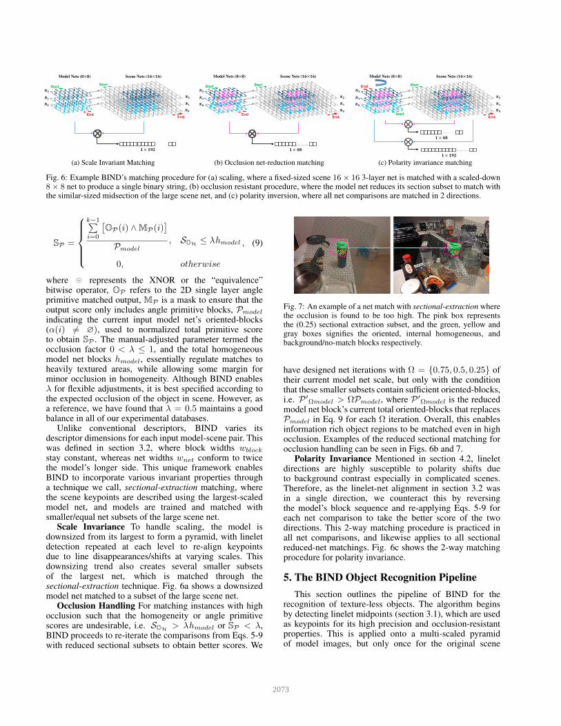
Fig. 6: Example BIND’s matching procedure for (a) scaling, where a fixed-sized scene 16× 16 3-layer net is matched with a scaled-down8× 8 net to produce a single binary string, (b) occlusion resistant procedure, where the model net reduces its section subset to match withthe similar-sized midsection of the large scene net, and (c) polarity inversion, where all net comparisons are matched in 2 directions.
SP =
k−1∑
i=0
[
OP(i) ∧MP(i)]
Pmodel
, SOH≤ λhmodel
0, otherwise
, (9)
where ⊙ represents the XNOR or the “equivalence”bitwise operator, OP refers to the 2D single layer angleprimitive matched output, MP is a mask to ensure that theoutput score only includes angle primitive blocks, Pmodel
indicating the current input model net’s oriented-blocks(α(i) 6= ∅), used to normalized total primitive scoreto obtain SP . The manual-adjusted parameter termed theocclusion factor 0 < λ ≤ 1, and the total homogeneousmodel net blocks hmodel, essentially regulate matches toheavily textured areas, while allowing some margin forminor occlusion in homogeneity. Although BIND enablesλ for flexible adjustments, it is best specified according tothe expected occlusion of the object in scene. However, asa reference, we have found that λ = 0.5 maintains a goodbalance in all of our experimental databases.
Unlike conventional descriptors, BIND varies itsdescriptor dimensions for each input model-scene pair. Thiswas defined in section 3.2, where block widths wblock
stay constant, whereas net widths wnet conform to twicethe model’s longer side. This unique framework enablesBIND to incorporate various invariant properties througha technique we call, sectional-extraction matching, wherethe scene keypoints are described using the largest-scaledmodel net, and models are trained and matched withsmaller/equal net subsets of the large scene net.
Scale Invariance To handle scaling, the model isdownsized from its largest to form a pyramid, with lineletdetection repeated at each level to re-align keypointsdue to line disappearances/shifts at varying scales. Thisdownsizing trend also creates several smaller subsetsof the largest net, which is matched through thesectional-extraction technique. Fig. 6a shows a downsizedmodel net matched to a subset of the large scene net.
Occlusion Handling For matching instances with highocclusion such that the homogeneity or angle primitivescores are undesirable, i.e. SOH
> λhmodel or SP < λ,BIND proceeds to re-iterate the comparisons from Eqs. 5-9with reduced sectional subsets to obtain better scores. We
Fig. 7: An example of a net match with sectional-extraction wherethe occlusion is found to be too high. The pink box representsthe (0.25) sectional extraction subset, and the green, yellow andgray boxes signifies the oriented, internal homogeneous, andbackground/no-match blocks respectively.
have designed net iterations with Ω = 0.75, 0.5, 0.25 oftheir current model net scale, but only with the conditionthat these smaller subsets contain sufficient oriented-blocks,i.e. P ′
Ωmodel > ΩPmodel, where P ′Ωmodel is the reduced
model net block’s current total oriented-blocks that replacesPmodel in Eq. 9 for each Ω iteration. Overall, this enablesinformation rich object regions to be matched even in highocclusion. Examples of the reduced sectional matching forocclusion handling can be seen in Figs. 6b and 7.
Polarity Invariance Mentioned in section 4.2, lineletdirections are highly susceptible to polarity shifts dueto background contrast especially in complicated scenes.Therefore, as the linelet-net alignment in section 3.2 wasin a single direction, we counteract this by reversingthe model’s block sequence and re-applying Eqs. 5-9 foreach net comparison to take the better score of the twodirections. This 2-way matching procedure is practiced inall net comparisons, and likewise applies to all sectionalreduced-net matchings. Fig. 6c shows the 2-way matchingprocedure for polarity invariance.
5. The BIND Object Recognition Pipeline
This section outlines the pipeline of BIND for therecognition of texture-less objects. The algorithm beginsby detecting linelet midpoints (section 3.1), which are usedas keypoints for its high precision and occlusion-resistantproperties. This is applied onto a multi-scaled pyramidof model images, but only once for the original scene
2073

0
0.1
0.2
0.3
0.4
0.5
0.6
0.7
0.8
0.9
1
0 0.1 0.2 0.3 0.4 0.5 0.6 0.7 0.8 0.9 1
Tru
e P
ositiv
e R
ate
(T
PR
)
False Positive Rate (FPR)
SIFT ORB BORDER BOLD Line2D BIND
(a) MOD
0
0.1
0.2
0.3
0.4
0.5
0.6
0.7
0.8
0.9
1
0 0.1 0.2 0.3 0.4 0.5 0.6 0.7 0.8 0.9 1
Tru
e P
ositiv
e R
ate
(T
PR
)
False Positive Rate (FPR)
SIFT ORB BORDER BOLD Line2D BIND
(b) D-Textureless
0
0.1
0.2
0.3
0.4
0.5
0.6
0.7
0.8
0.9
1
0 0.1 0.2 0.3 0.4 0.5 0.6 0.7 0.8 0.9 1
Tru
e P
ositiv
e R
ate
(T
PR
)
False Positives Per Image (FPPI)
rLINE2D+OCLP BORDER BOLD Line2D BIND
(c) CMU-KO8 Single
0
0.1
0.2
0.3
0.4
0.5
0.6
0.7
0.8
0.9
1
0 0.1 0.2 0.3 0.4 0.5 0.6 0.7 0.8 0.9 1
Tru
e P
ositiv
e R
ate
(T
PR
)
False Positives Per Image (FPPI)
rLINE2D+OCLP BORDER BOLD Line2D BIND
(d) CMU-KO8 Multi
0
0.5
1
1.5
2
2.5
3
3.5
Ave
rag
e T
ime
(s)
SIFT ORB BORDER BOLD Line2D BIND
(e) Average Runtimes
Fig. 8: Results of all experimental databases including the average time per image for the detectors.
(a) (b)
Fig. 9: MOD’s sample model images (a) and a scene image (b).
image. Following that, the enclosing boxes from eachpyramid level form the model binary nets (section 3.2),while assigning the largest net size for scene description.Next, each level of the model pyramid generates its ownindividual internal homogeneous mask (section 4.1) fortexture-less space encoding. Subsequently, nets are thentriple-layered, direction-aligned to each keypoint, and havetheir blocks identified for internal homogeneity and angleprimitives (section 4.2) before binary encoding using Table.1 (section 4.3). Finally, everything comes together in thematching phase (section 4.4) where the model nets at eachscale are compared with the large scene nets, and validatedusing geometric verification techniques [36, 37].
6. Experiments and Evaluation
To assess BIND’s overall competence in texture-lessobject recognition, we have employed several algorithmswith close relation to its qualities. For techniques thatspecialize in texture-less object detection, we engagestate-of-the-art works such as the line-based approach ofBORDER [3] and BOLD [4], together with the templatematching-based scheme of LINE-2D [16]. Moreover, asBIND can also be categorized as a binary keypoint-baseddetector, we have included standard detectors such asSIFT [1], and its binary-based alternative ORB [7]. Allmentioned algorithms including BIND, were implementedusing an Intel dual-core i7 Haswell processor with 8GBof memory, and coded in C++ with their default librariesand recommended settings as provided in their respectiveworks. A total of 3 texture-less object databases wereevaluated, with two taken publicly and one self-contributeddue to limited options in the texture-less object category.
The Messy Office Desk Dataset Coined MOD forshort, this database assembled by our team simulatesscenes of objects with high homogeneity placed aroundcommon workstations. It contains 9 models that randomlyfeature simultaneously within 100 scenes. Its aim is toappraise algorithms in a real environment on attributes likerotation, scale, translation, and distinctive properties suchas clutter and occlusion. In addition, objects in variousscenes of MOD are placed in random tonal backgroundsto challenge algorithms in complicated surroundings. Forthis experiment, we consolidate all the mentioned detectors’outcomes in an ROC plot as presented in Fig. 8a. Uponanalysis, local descriptors like SIFT and ORB, producedbelow par performance, whereas the texture-less basedsolutions excelled with BIND championing the overallexperiment. Although BORDER, BOLD and LINE-2Dalso had decent performances, a clear distinction betweenBIND can be observed especially in scenes whereobject edge-gradients are disordered by different regionalbackgrounds. This is mainly due to their high dependenceon gradient-direction for edge description, while BIND’spolarity invariant properties immunized itself to suchconditions. Fig. 9 exhibits some of the MOD databasemodels and a sample scene, while Fig. 10a presents someof BIND’s recognition results in the MOD dataset.
The D-Textureless Dataset This database by thecreators of BOLD [4], consists of 9 model and 55scene tool-based images. Each scene image containsmultiple models that examines algorithms on propertiessuch as rotation, scale, translation, occlusion and clutter.We evaluated all the above mentioned algorithms andconsolidated their ROC curves to yield the graph shownin Fig. 8b. As anticipated, texture-less detectors clearlyoutperforms the others, while BIND achieved the finestresults, outperforming both BORDER and BOLD by a fairmargin. Head-to-head analysis revealed that BIND tends toperform better than BORDER in circumstances that requirehigh precision, and BOLD in situations with nearby clutter.This can be mainly attributed to BIND’s highly-descriptivenet design, enabling encoding precision to both the object’shomogeneous space and its edges. Fig. 10b demonstratesthe precision and occlusion/clutter resistance of BIND inthis dataset with net-matching included.
The CMU-KO8 Dataset Also known as theCMU Kitchen Occlusion Dataset by Hsiao and
2074
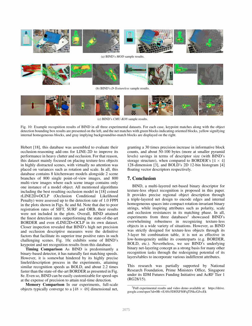
(a) BIND’s MOD sample results.
(b) BIND’s D-Textureless sample results.
(c) BIND’s CMU-KO8 sample results.
Fig. 10: Example recognition results of BIND in all three experimental datasets. For each case, keypoint matches along with the objectdetection bounding box results are presented on the left, and the net matches with green blocks indicating oriented blocks, yellow signifyinginternal homogeneous blocks, and gray implying background/no-match blocks are displayed on the right.
Hebert [18], this database was assembled to evaluate theirocclusion-reasoning add-ons for LINE-2D to improve itsperformance in heavy clutter and occlusion. For that reason,this dataset mainly focused on placing texture-less objectsin highly distracted scenes, with virtually no attention wasplaced on variances such as rotation and scale. In all, thisdatabase contains 8 kitchenware models alongside 2 scenebranches of 800 single point-of-view images, and 800multi-view images where each scene image contains onlyone instance of a model object. All mentioned algorithmsincluding the best resulting occlusion model in [18] coinedrLINE2D+OCLP (Occlusion Conditional LikelihoodPenalty) were assessed up to the detection rate of 1.0 FPPIin the plots shown in Figs. 8c and 8d. Note that due to poorregistration rates of SIFT, SURF and ORB, their resultswere not included in the plots. Overall, BIND attainedthe finest detection rates outperforming the state-of-the-artBORDER and even rLINE2D+OCLP in its own dataset.Closer inspection revealed that BIND’s high net precisionand occlusion descriptive measures were the definitivefactors that facilitate its superior true positive rates in suchchallenging scenes. Fig. 10c exhibits some of BIND’skeypoint and net recognition results from this database.
Timing Comparison As BIND is predominantly abinary-based detector, it has naturally fast matching speeds.However, it is somewhat hindered by its highly preciselinelet/description process in the experiments, attainingsimilar recognition speeds as BOLD, and about 2.2 timesfaster than the state-of-the-art BORDER as presented in Fig.8e. Even so, BIND can be easily customizable for speed-upsat the expense of precision to attain real-time detection.
Memory Comparison In our experiments, full-scaleobjects typically converge to a [48 × 48] dimensional net,
granting a 30 times precision increase in informative blockcounts, and about 50-100 bytes (more at smaller pyramidlevels) savings in terms of descriptor size (with BIND’sstorage structure), when compared to BORDER’s [4 × 4]128-dimension [3], and BOLD’s 2D 12-bin histogram [4]floating vector descriptors respectively.
7. Conclusion
BIND, a multi-layered net-based binary descriptor fortexture-less object recognition is proposed in this paper.It provides precise regional object description througha triple-layered net design to encode edges and internalhomogeneous spaces into compact rotation-invariant binarystrings, while inspiring attributes such as polarity, scaleand occlusion resistances in its matching phase. In all,experiments from three databases2 showcased BIND’soverwhelming robustness in recognizing texture-lessobjects in a wide variety of situations. However, as BINDwas strictly designed for texture-less objects through its3-layer bit combination table, it is not as effective inlow-homogeneity unlike its counterparts (e.g. BORDER,BOLD, etc.). Nevertheless, we see BIND’s underlyingbinary net-layering concept as a strong basis for many otherrecognition tasks through the redesigning potential of itslayers/tables to incorporate various indifferent attributes.
This research was partially supported by NationalResearch Foundation, Prime Ministers Office, Singaporeunder its IDM Futures Funding Initiative and AcRF Tier 1(RG28/15).
2Full experimental results and video demo available at: https://drive.google.com/open?id=0B-vEAVo5DHXFS0FqTlNkcGJvcEk
2075
References
[1] D. G. Lowe. Distinctive image features from scale-invariantkeypoints. IJCV, 60(2):91–110, 2004. 1, 7
[2] H. Bay, T. Tuytelaars, and L. J. Van Gool. Surf: speededup robust features. In Proc. ECCV, volume 3951, pages404–417, 2006. 1
[3] J. Chan, J. A. Lee, and K. Qian. Border: An orientedrectangles approach to texture-less object recognition. InProc. CVPR, 2016. 1, 2, 3, 4, 7, 8
[4] F. Tombari, A. Franchi, and L. Di Stefano. Bold features todetect texture-less objects. In Proc. ICCV, pages 1265–1272,2013. 1, 2, 3, 4, 7, 8
[5] S. Hinterstoisser, C. Cagniart, P S. Ilic, N. Navab Sturm,P. Fua, , and V. Lepetit. Gradient response maps for real-timedetection of textureless objects. PAMI, 34(5):876–888, 2012.1, 2
[6] M. Calonder, V. Lepetit, C. Strecha, and P. Fua. BRIEF:Binary Robust Independent Elementary Features. In ECCV,pages 778–792, 2010. 1
[7] E. Rublee, V. Rabaud, K. Konolige, and G. Bradski. Orb:an efficient alternative to sift or surf. In Proc. ICCV, pages2564–2571, 2011. 1, 7
[8] D. Damen, P. Bunnun, A. Calway, and W. Mayol-Cuevas.Real-time learning and detection of 3d texture-less objects: ascalable approach. In Proc. BMVC, pages 23.1–23.12, 2012.2, 3, 4
[9] H. G Barrow, J. M Tenenbaum, R. C. Bolles, and H. C.Wolf. Parametric Correspondence and Chamfer Matching:Two New Techniques for Image Matching. IJCAI, pages659–663, 1977. 2
[10] G. Borgefors. Hierarchical chamfer matching: a parametricedge matching algorithm. PAMI, 10(6):849–865, 1988. 2
[11] A. Thayananthan, B. Stenger, P. H. S. Torr, and R. Cipolla.Shape context and chamfer matching in cluttered scenes. InProc. CVPR, volume 1, pages I–127, 2003. 2
[12] C. Steger. Occlusion, clutter, and illumination invariantobject recognition. Intl Archives of Photogrammetry andRemote Sensing, 34, 2002. 2
[13] M. Y. Liu, O. Tuzel, A. Veeraraghavan, and R. Chellappa.Fast directional chamfer matching. In Proc. CVPR, pages1696–1703, 2010. 2
[14] C. F. Olson and D. P. Huttenlocher. Automatic targetrecognition by matching oriented edge pixels. IEEE Trans.Image Processing, 6(1):103–113, 1997. 2
[15] W. J. Rucklidge. Efficiently locating objects using thehausdorff distance. In Proc. IJCV, volume 24, pages251–270, 1997. 2
[16] S. Hinterstoisser, V. Lepetit, S. Ilic, P. Fua, and N. Navab.Dominant orientation templates for real-time detection oftexture-less objects. In Proc. CVPR, pages 2257–2264, 2010.2, 3, 4, 7
[17] X. Peng. Combine color and shape in real-time detectionof texture-less objects. Computer Vision and ImageUnderstanding, pages 31–48, 2015. 2
[18] E. Hsiao and M. Hebert. Occlusion reasoning for objectdetection under arbitrary viewpoint. In Proc. CVPR, pages3146–3153, 2012. 2, 8
[19] J. I. Olszewska. Where is My Cup? - Fully AutomaticDetection and Recognition of Textureless Objects inReal-World Images. CAIP, pages 501–512, 2015. 2
[20] M. Ulrich, C. Wiedemann, and C. Steger. Combiningscale-space and similarity-based aspect graphs for fast 3dobject recognition. PAMI, 34(10):1902–1914, 2012. 2
[21] V. Ferrari, L. Fevrier, F. Jurie, and C. Schmid. Groupsof adjacent contour segments for object detection. PAMI,87(3):284–303, 2007. 2
[22] V. Ferrari, F. Jurie, and C. Schmid. From images to shapemodels for object detection. In Proc. CVPR, pages 284–303,2009. 2
[23] S. Belongie, J. Malik, and J. Puzicha. Shape matchingand object recognition using shape contexts. PAMI,24(4):509–522, 2002. 2
[24] F. Jurie and C. Schmid. Scale-invariant shape features forrecognition of object categories. In Proc. CVPR, volume 2,pages II90–II96, 2004. 2
[25] O. Carmichael and M. Hebert. Shape-based recognition ofwiry objects. PAMI, 26(12):1537–1552, 2004. 2
[26] Y. Dou, M. Ye, P. Xu, L. Pei, and Z. Liu. Object DetectionBased on Two Level Fast Matching. International Journal ofMultimedia and Ubiquitous Engineering, 10(12):381–394,2015. 2
[27] R. G. von Gioi, J. Jakubowicz, J. M. Morel, and G. Randall.Lsd: a fast line segment detector with a false detectioncontrol. PAMI, 32(4):722–732, 2010. 2, 3
[28] P. David and D. DeMenthon. Object recognition in highclutter images using line features. In Proc. ICCV, pages1581–1588, 2005. 2, 3
[29] G. Kim, M. Hebert, and S.-K. Park. Preliminarydevelopment of a line feature-based object recognitionsystem for textureless indoor objects. In Proc. ICAR, pages255–268, 2007. 2, 3
[30] M. Awais and K. Mikolajczyk. Feature pairs connectedby lines for object recognition. In Proc. ICAR, pages3093–3096, 2010. 2, 3
[31] R. G. von Gioi, J. Jakubowicz, J. M. Morel, , and G. Randall.Lsd: a line segment detector. In Proc. IPOL, volume 2, pages35–55, 2012. 3
[32] A. Desolneux, L. Moisan, and J. M. Morel. From gestalttheory to image analysis: a probabilistic approach. ISBN:0387726357. Springer, 2008. 3
[33] J. ORourke. Finding minimal enclosing boxes.International Journal of Computer and InformationSciences, 14(3):183–199, 1985. 4
[34] F. Perazzi, P. Krhenbhl, Y. Pritch, and A. Hornung. Saliencyfilters: contrast based filtering for salient region detection. InProc. CVPR, pages 733–740, 2012. 4
[35] D. E. Ilea and P. F. Whelan. Color image segmentation usinga spatial k-means clustering algorithm. In Proc. IMVIP,2006. 4
[36] M. A. Fischler and R. C. Bolles. Random sample consensus:a paradigm for model fitting with applications to imageanalysis and automated cartography. Communications of theACM, 1981. 7
[37] J. Chan, J. A. Lee, and K. Qian. F-sort: An alternative forfaster geometric verification. In Proc. ACCV, 2016. 7
2076