binary media over ip moip setup guide for single switch
TRANSCRIPT

Source | Mute | 2ch(HDMI Out Audio)
BINARY MOIP SETUP GUIDE FOR PAKEDGE MS SERIES SWITCHES
MEDIA OVER IP SYSTEMAll B-900-MOIP-4K Units
2
INTRODUCTION
This document covers the basic configuration of a Binary MoIP system with MS Series
switches. This configuration works for most situations, but there are many variables which
could necessitate modifying this setup. Use this as a general guide to start your design and
configuration. Further help may be required from tech support.
If you’re using a multiple switch topology, one switch acts as the Core switch for a MoIP system.
This isn’t necessarily the core switch for the whole network, but this switch should have all
other MoIP switches connected directly to it and nowhere else. Connect the core MoIP switch
to your core network switch.
If you’re using a single, dedicated switch for your MoIP system you only need to follow the
setup instructions for “Core Switch configuration.” A VLAN can be configured, but isn’t
necessary.
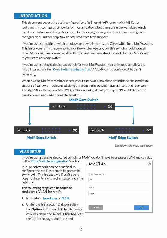
When placing MoIP transmitters throughout a network, pay close attention to the maximum
amount of bandwidth being used along different paths between transmitters and receivers.
Pakedge MS switches provide 10GBps SFP+ uplinks, allowing for up to 20 MoIP streams to
pass between each interconnected switch.
VLAN SETUP
If you’re using a single, dedicated switch for MoIP you don’t have to create a VLAN and can skip to the “Core Switch configuration” section.
In large networks it can be beneficial to configure the MoIP system to be part of its own VLAN. This isolates MoIP traffic so it does not interfere with other systems on the network.
The following steps can be taken to configure a VLAN for MoIP:
1. Navigate to Interfaces > VLAN
2. Under the first section Database click
the Option icon, then click Add to create
new VLANs on the switch. Click Apply at
the top of the page, when finished.
MoIP Edge Switch MoIP Edge Switch
MoIP Core Switch
Example of multiple switch topology.

3
3. Next, navigate to Interfaces > VLAN > Switchport Configuration. MS Switches support two
Switchport options for VLAN tagging:
a. Access - A single VLAN ID can be assigned to a port and all incoming traffic on that port is placed into that VLAN. The default for all ports on the switch is Access mode, with the VLAN set to 1.
b. Trunk - A single VLAN ID is set as the Untagged “Native VLAN.” Meaning any untagged, incoming traffic is assigned to that VLAN and any traffic outgoing for that VLAN is not tagged. A trunk port can be set to allow any number of VLANs as tagged traffic, so that traffic must be incoming or leaving on one of the specified VLANs.
4. All ports connected to MoIP devices
should be set with your MoIP VLAN on
Access.
5. Ports connected to your router, switch,
and access points should be set to Trunk.
IMPORTANT: Don’t forget to set up the VLAN in your router! See the router’s user manual for setup instructions.

4
CORE SWITCH CONFIGURATION
The steps that follow use the VLAN created from the previous section as an example. If you did not set up a MoIP VLAN, select the default network VLAN ID.
1. Switches running MoIP must have their MTU set to be greater than 8000 bytes. The default
configuration of MS switches is already set to the maximum of 9198. Double check this
under Interfaces > Port > Port Summary and by editing any port to view its details.
2. Navigate to Advanced > IGMP Snooping > Configuration. Set IGMP Snooping Global
Configuration Status Admin Mode to Enable.
3. Navigate to Advanced > IGMP Snooping > VLAN Status.
4. Click the Option button, then select Add.
5. Select the VLAN ID of the MoIP VLAN you
created.
Note: Do not enable Fast Leave on the Core switch. This could cause MoIP receivers on Edge switches to lose connection with a transmitter stream, if another receiver on the same Edge switch changes to a different transmitter stream.

5
6. Navigate to Advanced > IGMP Snooping Querier > Configuration and click the Admin
Mode toggle to make the Core switch the IGMP Snooping Querier. Leave IP Address at 0.0.0.0. Admin Mode enables IGMP globally so the steps that follow are effective. An IP address of all zeros makes the switch reference itself, ensuring that it is your IGMP Querier. This protects you against any issues that could come from changing DHCP addresses. IMPORTANT: Only enable IGMP Snooping Querier on the Core switch.
7. Under IGMP Version, select IGMP V2.
9. Under IGMP Snooping Querier, go to VLAN Configuration and click the Option button, then Add.
a. Select the VLAN ID for the VLAN which is running IGMP Snooping.
b. Leave Querier Election Participation disabled. You’ve manually set the Core switch as the querier.
c. Leave the Querier VLAN IP Address at 0.0.0.0. An IP address of all zeros makes sure that this switch remains the IGMP querier for the network.
IMPORTANT: Do not enable Querier Election Participation because you are manually setting the Core switch in the network as the querier, and you’re leaving querier disabled on the edge switches.
Leave Querier VLAN IP Address at 0.0.0.0.
6
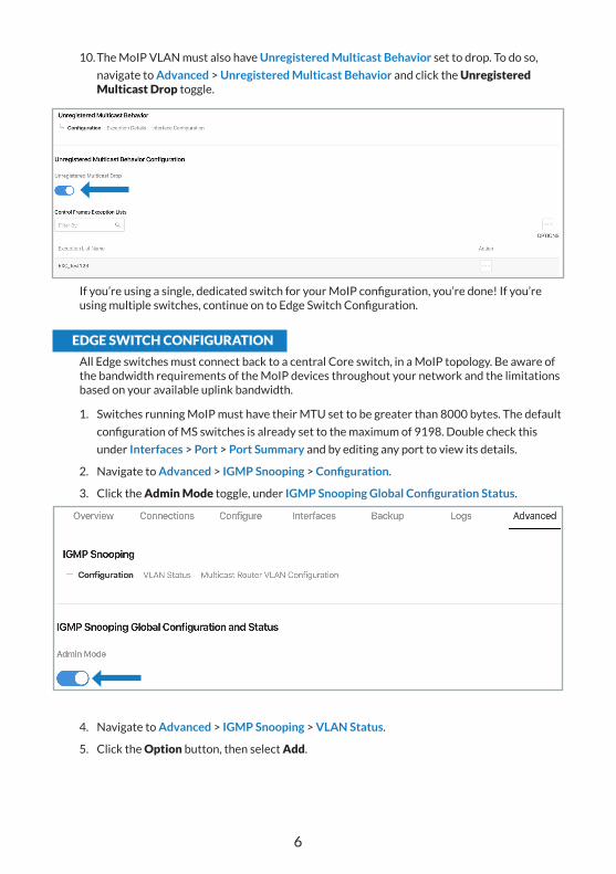
10. The MoIP VLAN must also have Unregistered Multicast Behavior set to drop. To do so,
navigate to Advanced > Unregistered Multicast Behavior and click the Unregistered Multicast Drop toggle.
If you’re using a single, dedicated switch for your MoIP configuration, you’re done! If you’re using multiple switches, continue on to Edge Switch Configuration.
EDGE SWITCH CONFIGURATION
All Edge switches must connect back to a central Core switch, in a MoIP topology. Be aware of the bandwidth requirements of the MoIP devices throughout your network and the limitations based on your available uplink bandwidth.
1. Switches running MoIP must have their MTU set to be greater than 8000 bytes. The default
configuration of MS switches is already set to the maximum of 9198. Double check this
under Interfaces > Port > Port Summary and by editing any port to view its details.
2. Navigate to Advanced > IGMP Snooping > Configuration.
3. Click the Admin Mode toggle, under IGMP Snooping Global Configuration Status.
4. Navigate to Advanced > IGMP Snooping > VLAN Status.
5. Click the Option button, then select Add.

7
6. Select the VLAN ID of the MoIP VLAN.
IMPORTANT: IGMP Snooping Querier should not be enabled in Edge switches. If you choose to enable it, great care must be given to ensure the correct switch is acting as the querier, and it is important to calculate bandwidth for changing flows. Whichever switch is elected as the querier forwards all MoIP traffic to that switch. This is normal operation for multicast and IGMP.

Rev: 201125-1124 Copyright ©2020, Wirepath Home Systems, LLC. All rights reserved. Control4 and Snap AV and
their respective logos are registered trademarks or trademarks of Wirepath Home Systems, LLC, dba “Control4” and/or dba “SnapAV” in the United States and/or other countries. Snap AV and
Binary are also registered trademarks or trademarks of Wirepath Home Systems, LLC. Other names and brands may be claimed as the property of their respective owners. All specifications subject to
change without notice.
7. The MoIP VLAN must also have Unregistered Multicast Behavior set to drop. To do so,
navigate to Advanced > Unregistered Multicast Behavior and click the Unregistered Multicast Drop toggle.