bim for advanced daylighting
TRANSCRIPT

BIM for Advanced Daylighting Brian Skripac, Assoc. AIA, LEED AP BD+C – DesignGroup
MP4568�P Class Description
A well day lit building can provide significant energy reductions and reduced operating costs for building owners of not only new construction projects but existing facilities. With electric lighting accounting for 35 to 50 percent of the total electrical energy consumption in commercial buildings, design teams can leverage the optimal integration of daylighting strategies to offset this impact. This session will define the best practices and processes of implementing a BIM workflow with Revit Architecture and Ecotect Analysis. Additionally, we will outline the relevant project properties needed to accurately obtain the quality and reliable analytical information to effectively validate design decisions that can have the most beneficial impact on the building’s performance and lifecycle costs.
Learning Objectives At the end of this class, you will be able to:
• Define the energy impacts and performance benefits from natural daylighting.
• Identify a workflow to optimize your existing Revit geometry in Ecotect.
• Define the key material performance properties that will impact your analysis results.
• Demonstrate the effective use of Ecotect and the Radiance plug3in to document the natural daylight levels in a space.
About the Speaker
As the Director of BIM at DesignGroup, Brian Skripac leads the integration of building information modeling (BIM) technologies for all projects. Currently, he is actively engaged in the research and application of sustainable technologies for use in project designs. In addition to managing BIM, Brian is frequently solicited by institutions, as well as professional organizations, to present his expertise. Brian has transformed the firm's approach to design and construction; and he seeks to educate clients, consultants, and colleagues on the benefits and value BIM brings to industry. Brian holds a bachelor of science in architecture from The Ohio State University, is a LEED® accredited professional, and an Autodesk® Revit® Architecture certified professional. He currently serves as an Advisory Group member for the AIA Technology in Architectural Practice Knowledge Community (TAP KC) at the national level, as well as being the chair of the AIA Columbus TAP KC. Email: [email protected] Twitter: @BrianSkripac
BIM for Advanced Daylighting
2
Energy impacts and performance benefits from natural daylighting.
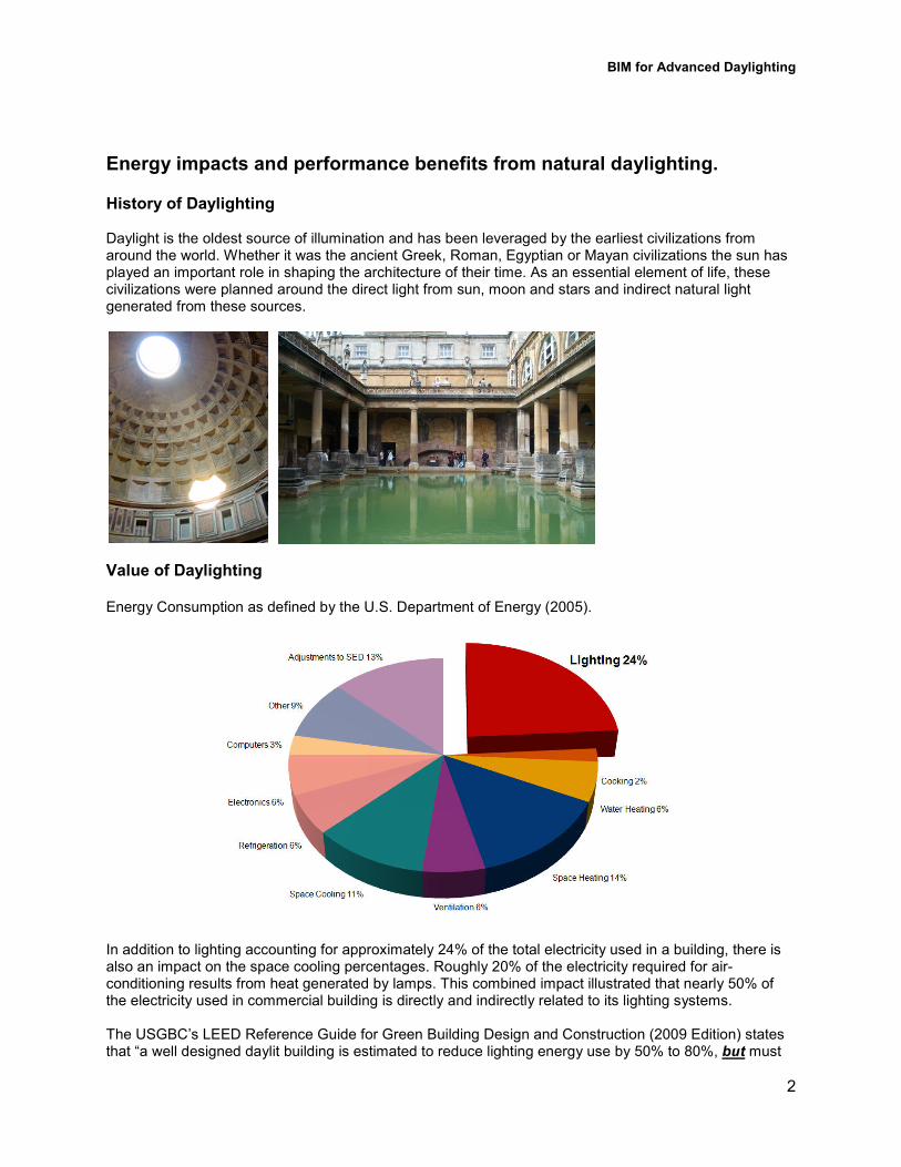
History of Daylighting Daylight is the oldest source of illumination and has been leveraged by the earliest civilizations from around the world. Whether it was the ancient Greek, Roman, Egyptian or Mayan civilizations the sun has played an important role in shaping the architecture of their time. As an essential element of life, these civilizations were planned around the direct light from sun, moon and stars and indirect natural light generated from these sources.
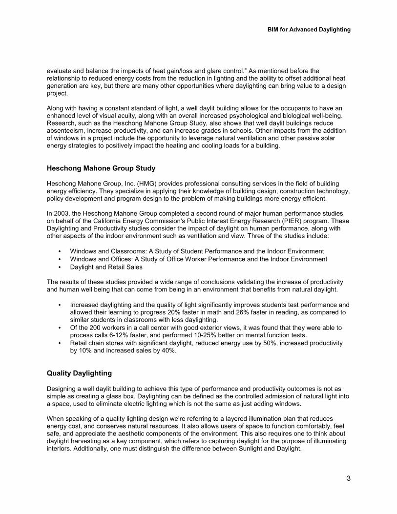
Value of Daylighting Energy Consumption as defined by the U.S. Department of Energy (2005).
In addition to lighting accounting for approximately 24% of the total electricity used in a building, there is also an impact on the space cooling percentages. Roughly 20% of the electricity required for air3conditioning results from heat generated by lamps. This combined impact illustrated that nearly 50% of the electricity used in commercial building is directly and indirectly related to its lighting systems. The USGBC’s LEED Reference Guide for Green Building Design and Construction (2009 Edition) states that “a well designed daylit building is estimated to reduce lighting energy use by 50% to 80%, but must
BIM for Advanced Daylighting
3
evaluate and balance the impacts of heat gain/loss and glare control.” As mentioned before the relationship to reduced energy costs from the reduction in lighting and the ability to offset additional heat generation are key, but there are many other opportunities where daylighting can bring value to a design project. Along with having a constant standard of light, a well daylit building allows for the occupants to have an enhanced level of visual acuity, along with an overall increased psychological and biological well3being. Research, such as the Heschong Mahone Group Study, also shows that well daylit buildings reduce absenteeism, increase productivity, and can increase grades in schools. Other impacts from the addition of windows in a project include the opportunity to leverage natural ventilation and other passive solar energy strategies to positively impact the heating and cooling loads for a building.
Heschong Mahone Group Study Heschong Mahone Group, Inc. (HMG) provides professional consulting services in the field of building energy efficiency. They specialize in applying their knowledge of building design, construction technology, policy development and program design to the problem of making buildings more energy efficient. In 2003, the Heschong Mahone Group completed a second round of major human performance studies on behalf of the California Energy Commission's Public Interest Energy Research (PIER) program. These Daylighting and Productivity studies consider the impact of daylight on human performance, along with other aspects of the indoor environment such as ventilation and view. Three of the studies include:
• Windows and Classrooms: A Study of Student Performance and the Indoor Environment
• Windows and Offices: A Study of Office Worker Performance and the Indoor Environment
• Daylight and Retail Sales The results of these studies provided a wide range of conclusions validating the increase of productivity and human well being that can come from being in an environment that benefits from natural daylight.
• Increased daylighting and the quality of light significantly improves students test performance and allowed their learning to progress 20% faster in math and 26% faster in reading, as compared to similar students in classrooms with less daylighting.
• Of the 200 workers in a call center with good exterior views, it was found that they were able to process calls 6312% faster, and performed 10325% better on mental function tests.
• Retail chain stores with significant daylight, reduced energy use by 50%, increased productivity by 10% and increased sales by 40%.
Quality Daylighting
Designing a well daylit building to achieve this type of performance and productivity outcomes is not as simple as creating a glass box. Daylighting can be defined as the controlled admission of natural light into a space, used to eliminate electric lighting which is not the same as just adding windows. When speaking of a quality lighting design we’re referring to a layered illumination plan that reduces energy cost, and conserves natural resources. It also allows users of space to function comfortably, feel safe, and appreciate the aesthetic components of the environment. This also requires one to think about daylight harvesting as a key component, which refers to capturing daylight for the purpose of illuminating interiors. Additionally, one must distinguish the difference between Sunlight and Daylight.

BIM for Advanced Daylighting
4
Sunlight vs. Daylight
• Sunlight is considered light that enters a space directly from the sun. This type of light is generally not good lighting for an interior. Direct sunlight can produce glare and excessive heat, which can fade materials.
• Daylight or skylight is the term that describes the desirable natural light in a space. Daylight results in a perceived even distribution of light that avoids the glare and ill effects of the direct sun3light.
Daylighting Design At DesignGroup, when designing with daylight and passive design strategies, we use the process “Energy as a Formgiver” and always think about the following question: What is the Impact of _______ on Building Performance & Energy Consumption?
• Building Proportion
• Window to Wall Ratio
• Building Orientation
• Shading Devices Utilizing these passive strategies with an iterative design process to gather analysis information from the outset of a design project can help shape the form and envelope conditions of a building. With this information available from the earliest stages of design you can have the most beneficial impact on a building’s performance and lifecycle costs. This also allows the design team to take advantage of their local climate conditions and having the building geometry react specifically to its site creating unique outcomes. In the United States it is important to balance southern and northern exposures against the east and west.
• South facing glass allows for a high level of daylight but must control glare while maintaining natural light levels as well as balancing the wanted and unwanted solar gains of the summer/winter months.
• North facing glass is ideal for letting even natural light in with little glare or solar gains.
• East and West glass doesn’t work as well for daylighting. They capture a lot of light during the morning and afternoon, but also come with excessive glare and unwanted heat in the summer months.
• Other useful design features can include the use of the following: roof monitors and clerestories, multistory spaces, roof overhangs and sunshades, and light shelves
These ideas all allow for context specific outcomes where building form, shape, fenestration, roof overhangs, light shelves and awning can become site specific resulting in unique architecture. The following link from the Energy.gov website has a great overview of daylighting called Energy 101: Daylighting 3 http://energy.gov/building3design
BIM for Advanced Daylighting
5
These strategies can also have positive outcomes in optimizing design decisions for existing buildings. Being able to simulate illuminance values in existing building spaces can provide the quantitative feedback owners need to make evidence based decisions on whether or not to make capital investments on investment re3lamping initiatives for their facilities.
Case Study:
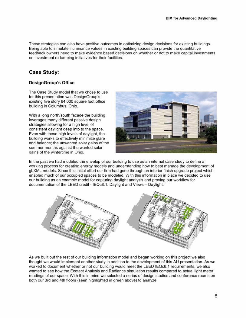
DesignGroup’s Office The Case Study model that we chose to use for this presentation was DesignGroup’s existing five story 64,000 square foot office building in Columbus, Ohio. With a long north/south facade the building leverages many different passive design strategies allowing for a high level of consistent daylight deep into to the space. Even with these high levels of daylight, the building works to effectively minimize glare and balance; the unwanted solar gains of the summer months against the wanted solar gains of the wintertime in Ohio. In the past we had modeled the envelop of our building to use as an internal case study to define a working process for creating energy models and understanding how to best manage the development of gbXML models. Since this initial effort our firm had gone through an interior finish upgrade project which enabled much of our occupied spaces to be modeled. With this information in place we decided to use our building as an example model for capturing daylight analysis and proving our workflow for documentation of the LEED credit 3 IEQc8.1: Daylight and Views – Daylight.
As we built out the rest of our building information model and began working on this project we also thought we would implement another study in addition to the development of this AU presentation. As we worked to document whether or not our building would meet the LEED IEQc8.1 requirements, we also wanted to see how the Ecotect Analysis and Radiance simulation results compared to actual light meter readings of our space. With this in mind we selected a series of design studios and conference rooms on both our 3rd and 4th floors (seen highlighted in green above) to analyze.

BIM for Advanced Daylighting
6
To begin to understand these specific areas of our building we ran through a process of first isolating those areas of our Revit model then bringing them into Ecotect to define an analysis grid. Able to utilize that information back in Revit Architecture we the documented a series of work points that we could then reference as regularly occupied spaces for the LEED documentation process. We also built a light meter node family in the Revit model to hold both the existing and simulation illuminance value readings which was used to generate schedules and other comparative results.
The analysis grid we used was based the LEED IEQc8.1 documentation requirements which we will discuss later in this document. This resulted in capturing 178 light meter reading points that were transferred onto the floor with blue painters tape. With this information in place our team took readings at each point in the office at 9:00 a.m. and 3:00 p.m., (following the LEED credit criteria). We also took readings at 12:00 p.m. to capture the sun at its highest point in the sky. This process started on the Summer Solstice and was repeated on the 21
st of each month through September to drive a consistency
of measurements.
This effort proved to be an extremely educational process that allowed us to document how our space was performing and how it compared to an Ecotect simulation. It also allowed us to establish a process for using a BIM workflow to document the LEED IEQc8.1 credit for both new and existing building projects.
BIM for Advanced Daylighting
7
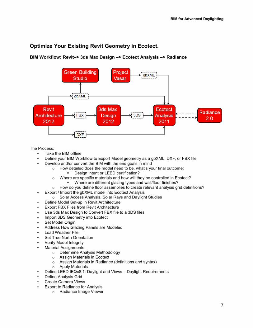
Optimize Your Existing Revit Geometry in Ecotect.
BIM Workflow: Revit–> 3ds Max Design –> Ecotect Analysis –> Radiance
The Process:
• Take the BIM offline
• Define your BIM Workflow to Export Model geometry as a gbXML, DXF, or FBX file
• Develop and/or convert the BIM with the end goals in mind o How detailed does the model need to be, what’s your final outcome:
� Design intent or LEED certification? o Where are specific materials and how will they be controlled in Ecotect?
� Where are different glazing types and wall/floor finishes? o How do you define floor assemblies to create relevant analysis grid definitions?
• Export / Import the gbXML model into Ecotect Analysis o Solar Access Analysis, Solar Rays and Daylight Studies
• Define Model Set3up in Revit Architecture
• Export FBX Files from Revit Architecture
• Use 3ds Max Design to Convert FBX file to a 3DS files
• Import 3DS Geometry into Ecotect
• Set Model Origin
• Address How Glazing Panels are Modeled
• Load Weather File
• Set True North Orientation
• Verify Model Integrity
• Material Assignments o Determine Analysis Methodology o Assign Materials in Ecotect o Assign Materials in Radiance (definitions and syntax) o Apply Materials
• Define LEED IEQc8.1: Daylight and Views – Daylight Requirements
• Define Analysis Grid
• Create Camera Views
• Export to Radiance for Analysis o Radiance Image Viewer
BIM for Advanced Daylighting
8
o Radiance Import
• Analysis Grid Management o Changing Analysis Grid from Lux to Footcandles o Import and/or Export Analysis Grid Data
• Outcomes o Data Output Options o LEED IEQc8.1: Daylight and Views – Daylight Documentation o Model Run Comparisons
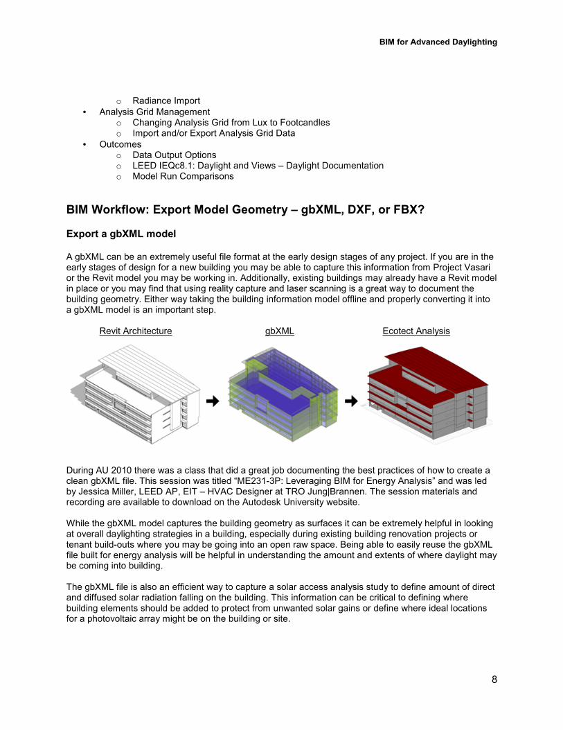
BIM Workflow: Export Model Geometry – gbXML, DXF, or FBX? Export a gbXML model A gbXML can be an extremely useful file format at the early design stages of any project. If you are in the early stages of design for a new building you may be able to capture this information from Project Vasari or the Revit model you may be working in. Additionally, existing buildings may already have a Revit model in place or you may find that using reality capture and laser scanning is a great way to document the building geometry. Either way taking the building information model offline and properly converting it into a gbXML model is an important step.
Revit Architecture gbXML Ecotect Analysis
During AU 2010 there was a class that did a great job documenting the best practices of how to create a clean gbXML file. This session was titled “ME23133P: Leveraging BIM for Energy Analysis” and was led by Jessica Miller, LEED AP, EIT – HVAC Designer at TRO Jung|Brannen. The session materials and recording are available to download on the Autodesk University website. While the gbXML model captures the building geometry as surfaces it can be extremely helpful in looking at overall daylighting strategies in a building, especially during existing building renovation projects or tenant build3outs where you may be going into an open raw space. Being able to easily reuse the gbXML file built for energy analysis will be helpful in understanding the amount and extents of where daylight may be coming into building. The gbXML file is also an efficient way to capture a solar access analysis study to define amount of direct and diffused solar radiation falling on the building. This information can be critical to defining where building elements should be added to protect from unwanted solar gains or define where ideal locations for a photovoltaic array might be on the building or site.
BIM for Advanced Daylighting
9
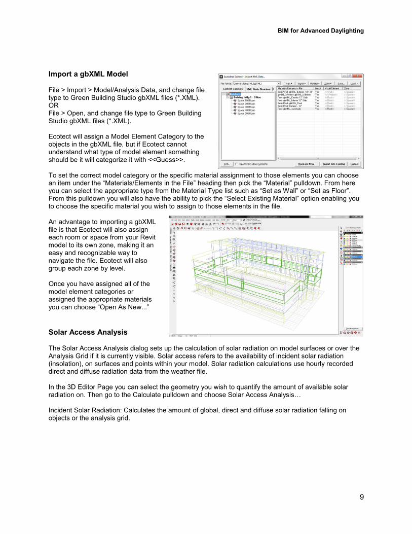
Import a gbXML Model File > Import > Model/Analysis Data, and change file type to Green Building Studio gbXML files (*.XML). OR File > Open, and change file type to Green Building Studio gbXML files (*.XML). Ecotect will assign a Model Element Category to the objects in the gbXML file, but if Ecotect cannot understand what type of model element something should be it will categorize it with <<Guess>>. To set the correct model category or the specific material assignment to those elements you can choose an item under the “Materials/Elements in the File” heading then pick the “Material” pulldown. From here you can select the appropriate type from the Material Type list such as “Set as Wall” or “Set as Floor”. From this pulldown you will also have the ability to pick the “Select Existing Material” option enabling you to choose the specific material you wish to assign to those elements in the file. An advantage to importing a gbXML file is that Ecotect will also assign each room or space from your Revit model to its own zone, making it an easy and recognizable way to navigate the file. Ecotect will also group each zone by level. Once you have assigned all of the model element categories or assigned the appropriate materials you can choose “Open As New...”
Solar Access Analysis The Solar Access Analysis dialog sets up the calculation of solar radiation on model surfaces or over the Analysis Grid if it is currently visible. Solar access refers to the availability of incident solar radiation (insolation), on surfaces and points within your model. Solar radiation calculations use hourly recorded direct and diffuse radiation data from the weather file. In the 3D Editor Page you can select the geometry you wish to quantify the amount of available solar radiation on. Then go to the Calculate pulldown and choose Solar Access AnalysisS Incident Solar Radiation: Calculates the amount of global, direct and diffuse solar radiation falling on objects or the analysis grid.
BIM for Advanced Daylighting
10
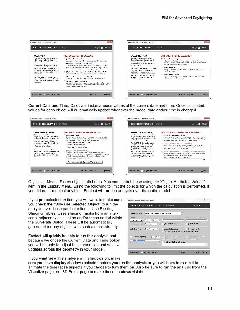
Current Date and Time: Calculate instantaneous values at the current date and time. Once calculated, values for each object will automatically update whenever the model date and/or time is changed.
Objects in Model: Stores objects attributes. You can control these using the “Object Attributes Values” item in the Display Menu. Using the following to limit the objects for which the calculation is performed. If you did not pre3select anything, Ecotect will run the analysis over the entire model. If you pre3selected an item you will want to make sure you check the “Only use Selected Object” to run the analysis over those particular items. Use Existing Shading Tables: Uses shading masks from an inter3zonal adjacency calculation and/or those added within the Sun3Path Dialog. These will be automatically generated for any objects with such a mask already. Ecotect will quickly be able to run this analysis and because we chose the Current Date and Time option you will be able to adjust these variables and see live updates across the geometry in your model. If you want view this analysis with shadows on, make sure you have display shadows selected before you run the analysis or you will have to re3run it to animate the time lapse aspects if you choose to turn them on. Also be sure to run the analysis from the Visualize page, not 3D Editor page to make those shadows visible.
BIM for Advanced Daylighting
11
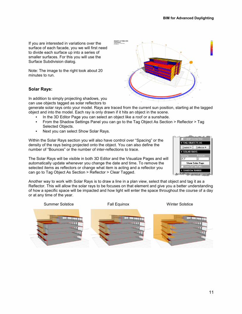
If you are interested in variations over the surface of each facade, you we will first need to divide each surface up into a series of smaller surfaces. For this you will use the Surface Subdivision dialog. Note: The image to the right took about 20 minutes to run.
Solar Rays: In addition to simply projecting shadows, you can use objects tagged as solar reflectors to generate solar rays onto your model. Rays are traced from the current sun position, starting at the tagged object and into the model. Each ray is only drawn if it hits an object in the scene.
• In the 3D Editor Page you can select an object like a roof or a sunshade.
• From the Shadow Settings Panel you can go to the Tag Object As Section > Reflector > Tag Selected Objects.
• Next you can select Show Solar Rays. Within the Solar Rays section you will also have control over “Spacing” or the density of the rays being projected onto the object. You can also define the number of “Bounces” or the number of inter3reflections to trace. The Solar Rays will be visible in both 3D Editor and the Visualize Pages and will automatically update whenever you change the date and time. To remove the selected items as reflectors or change what item is acting and a reflector you can go to Tag Object As Section > Reflector > Clear Tagged. Another way to work with Solar Rays is to draw a line in a plan view, select that object and tag it as a Reflector. This will allow the solar rays to be focuses on that element and give you a better understanding of how a specific space will be impacted and how light will enter the space throughout the course of a day or at any time of the year.
Summer Solstice Fall Equinox Winter Solstice
BIM for Advanced Daylighting
12
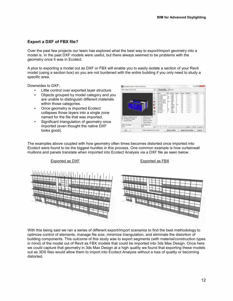
Export a DXF of FBX file? Over the past few projects our team has explored what the best way to export/import geometry into a model is. In the past DXF models were useful, but there always seemed to be problems with the geometry once it was in Ecotect. A plus to exporting a model out as DXF or FBX will enable you to easily isolate a section of your Revit model (using a section box) so you are not burdened with the entire building if you only need to study a specific area. Downsides to DXF:
• Little control over exported layer structure
• Objects grouped by model category and you are unable to distinguish different materials within those categories.
• Once geometry is imported Ecotect collapses those layers into a single zone named for the file that was imported.
• Significant triangulation of geometry once imported (even thought the native DXF looks good).
The examples above coupled with how geometry often times becomes distorted once imported into Ecotect were found to be the biggest hurdles in this process. One common example is how curtainwall mullions and panels translate when imported into Ecotect Analysis via a DXF file as seen below.
Exported as DXF Exported as FBX
With this being said we ran a series of different export/import scenarios to find the best methodology to optimize control of elements, manage file size, minimize triangulation, and eliminate the distortion of building components. This outcome of this study was to export segments (with material/construction types in mind) of the model out of Revit as FBX models that could be imported into 3ds Max Design. Once here we could capture that geometry in 3ds Max Design at a high quality we found that exporting these models out as 3DS files would allow them to import into Ecotect Analysis without a loss of quality or becoming distorted.
BIM for Advanced Daylighting
13
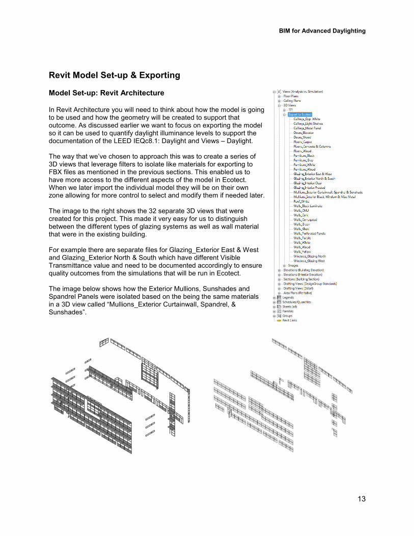
Revit Model Set�up & Exporting Model Set�up: Revit Architecture In Revit Architecture you will need to think about how the model is going to be used and how the geometry will be created to support that outcome. As discussed earlier we want to focus on exporting the model so it can be used to quantify daylight illuminance levels to support the documentation of the LEED IEQc8.1: Daylight and Views – Daylight. The way that we’ve chosen to approach this was to create a series of 3D views that leverage filters to isolate like materials for exporting to FBX files as mentioned in the previous sections. This enabled us to have more access to the different aspects of the model in Ecotect. When we later import the individual model they will be on their own zone allowing for more control to select and modify them if needed later. The image to the right shows the 32 separate 3D views that were created for this project. This made it very easy for us to distinguish between the different types of glazing systems as well as wall material that were in the existing building. For example there are separate files for Glazing_Exterior East & West and Glazing_Exterior North & South which have different Visible Transmittance value and need to be documented accordingly to ensure quality outcomes from the simulations that will be run in Ecotect. The image below shows how the Exterior Mullions, Sunshades and Spandrel Panels were isolated based on the being the same materials in a 3D view called “Mullions_Exterior Curtainwall, Spandrel, & Sunshades”.

BIM for Advanced Daylighting
14
The 3D model export views above titled “Mullions_Exterior Curtainwall, Spandrel, & Sunshades” were able to be created using three filters for the model:
• 00_Exterior_Solid Panels
• 00_Exterior_Sunshades
• 00_Exterior_Mullions_Clear Anodized We created all of the filters in the model based on understanding either the Family and Type Name parameter of the families in the project. Ideally we would have looked to use materials to filter objects by, but this is not a parameter that is available. Each 3D view could be comprised of multiple filters to capture all of the like elements that would need to be exported. For example there were two Generic Model families that made up the exterior sunshades on the building (one for the horizontal members and one for the vertical bracket). To be able to capture those items a filter was set3up to capture Generic Models who’s Type Name “begins with” 003Exterior3Sushade which allowed multiple families to be picked up. This was a process that we were able to replicate throughout the model for exterior as well as interior elements.
BIM for Advanced Daylighting
15
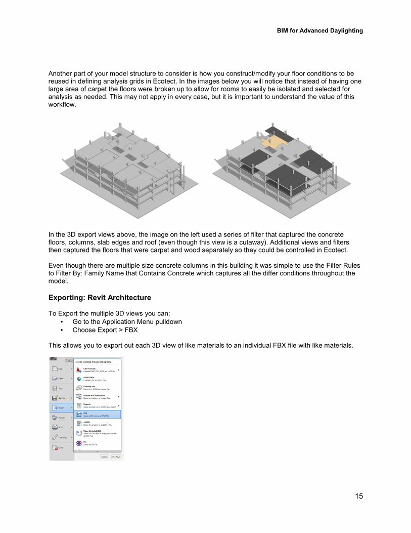
Another part of your model structure to consider is how you construct/modify your floor conditions to be reused in defining analysis grids in Ecotect. In the images below you will notice that instead of having one large area of carpet the floors were broken up to allow for rooms to easily be isolated and selected for analysis as needed. This may not apply in every case, but it is important to understand the value of this workflow.
In the 3D export views above, the image on the left used a series of filter that captured the concrete floors, columns, slab edges and roof (even though this view is a cutaway). Additional views and filters then captured the floors that were carpet and wood separately so they could be controlled in Ecotect. Even though there are multiple size concrete columns in this building it was simple to use the Filter Rules to Filter By: Family Name that Contains Concrete which captures all the differ conditions throughout the model.
Exporting: Revit Architecture To Export the multiple 3D views you can:
• Go to the Application Menu pulldown
• Choose Export > FBX This allows you to export out each 3D view of like materials to an individual FBX file with like materials.
BIM for Advanced Daylighting
16
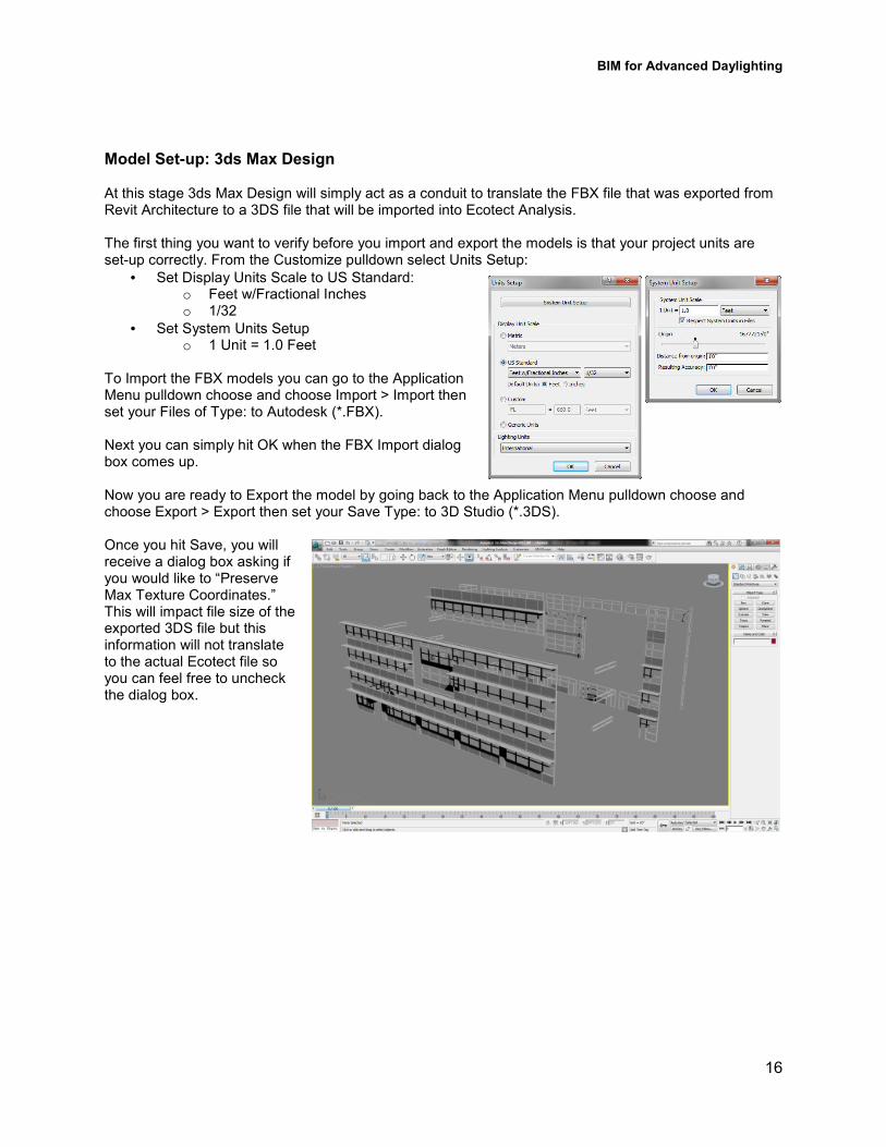
Model Set�up: 3ds Max Design At this stage 3ds Max Design will simply act as a conduit to translate the FBX file that was exported from Revit Architecture to a 3DS file that will be imported into Ecotect Analysis. The first thing you want to verify before you import and export the models is that your project units are set3up correctly. From the Customize pulldown select Units Setup:
• Set Display Units Scale to US Standard: o Feet w/Fractional Inches o 1/32
• Set System Units Setup o 1 Unit = 1.0 Feet
To Import the FBX models you can go to the Application Menu pulldown choose and choose Import > Import then set your Files of Type: to Autodesk (*.FBX). Next you can simply hit OK when the FBX Import dialog box comes up. Now you are ready to Export the model by going back to the Application Menu pulldown choose and choose Export > Export then set your Save Type: to 3D Studio (*.3DS). Once you hit Save, you will receive a dialog box asking if you would like to “Preserve Max Texture Coordinates.” This will impact file size of the exported 3DS file but this information will not translate to the actual Ecotect file so you can feel free to uncheck the dialog box.
BIM for Advanced Daylighting
17
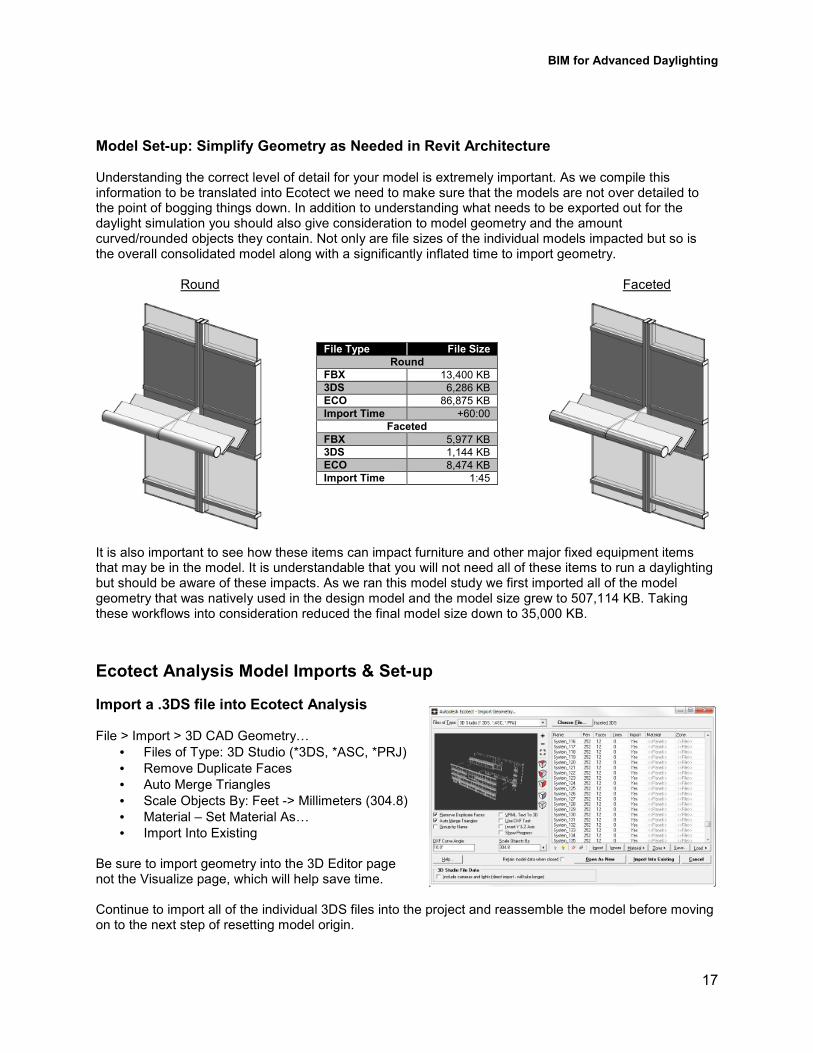
Model Set�up: Simplify Geometry as Needed in Revit Architecture Understanding the correct level of detail for your model is extremely important. As we compile this information to be translated into Ecotect we need to make sure that the models are not over detailed to the point of bogging things down. In addition to understanding what needs to be exported out for the daylight simulation you should also give consideration to model geometry and the amount curved/rounded objects they contain. Not only are file sizes of the individual models impacted but so is the overall consolidated model along with a significantly inflated time to import geometry. Round Faceted
It is also important to see how these items can impact furniture and other major fixed equipment items that may be in the model. It is understandable that you will not need all of these items to run a daylighting but should be aware of these impacts. As we ran this model study we first imported all of the model geometry that was natively used in the design model and the model size grew to 507,114 KB. Taking these workflows into consideration reduced the final model size down to 35,000 KB.
Ecotect Analysis Model Imports & Set�up
Import a .3DS file into Ecotect Analysis File > Import > 3D CAD GeometryS
• Files of Type: 3D Studio (*3DS, *ASC, *PRJ)
• Remove Duplicate Faces
• Auto Merge Triangles
• Scale Objects By: Feet 3> Millimeters (304.8)
• Material – Set Material AsS
• Import Into Existing Be sure to import geometry into the 3D Editor page not the Visualize page, which will help save time. Continue to import all of the individual 3DS files into the project and reassemble the model before moving on to the next step of resetting model origin.
File Type File Size
Round
FBX 13,400 KB
3DS 6,286 KB
ECO 86,875 KB
Import Time +60:00
Faceted
FBX 5,977 KB
3DS 1,144 KB
ECO 8,474 KB
Import Time 1:45

BIM for Advanced Daylighting
18
Set Origin
Depending on where your origin is in your Revit model you may find that it needs to be redefined accordingly once you import your geometry into Ecotect. For instance if you building’s first floor (base level or origin) is set generically to 100’30” or specifically to an above sea level elevation like 742’39” in Revit you will have to address this to correctly define the ground plane in Ecotect Analysis. To define the ground plane in your project you can use the Set Origin button in the toolbars. Once you define a point in the model to serve as the origin, you are ready to “Rest World Origin”.
• Go to the Modify pulldown
• Select Transform Origin
• Reset World Origin As seen in the images below, if you have redefined your origin then import additional geometry it will not fall into the correct location as before the origin was redefined. You will need to have a consistent point defined in the model to be able to move the geometry from one location to the other, but this can be done. Origin not re3defined Origin re3defined and geometry imported
Model Setup: Glazing Panels
Another important consideration in Ecotect is to understand how the glazing elements modeled in Revit Architecture will function and perform in Ecotect Analysis. The geometry that comes across from Revit will have a panel of glass represented as solid objects with six faces. This is acceptable for solid or opaque objects in Ecotect, but for glazing and transparent/translucent objects which will cause a high level of inaccuracy to your analysis outcomes.
BIM for Advanced Daylighting
19
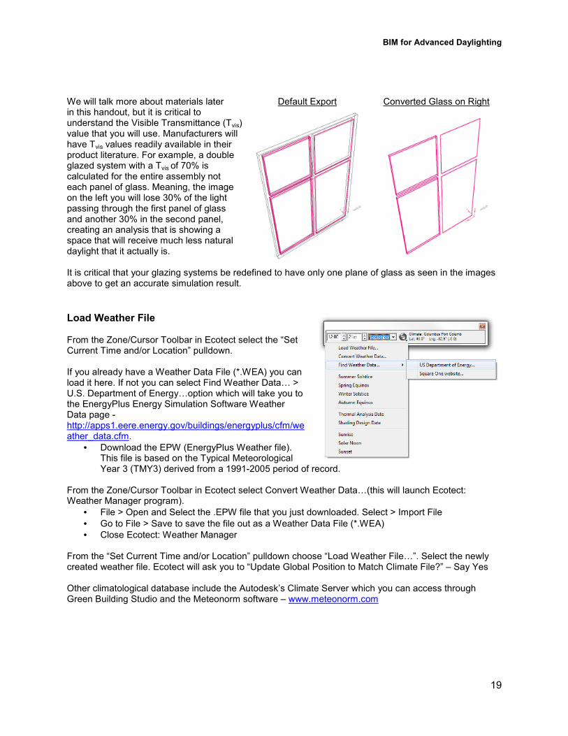
We will talk more about materials later Default Export Converted Glass on Right in this handout, but it is critical to understand the Visible Transmittance (Tvis) value that you will use. Manufacturers will have Tvis values readily available in their product literature. For example, a double glazed system with a Tvis of 70% is calculated for the entire assembly not each panel of glass. Meaning, the image on the left you will lose 30% of the light passing through the first panel of glass and another 30% in the second panel, creating an analysis that is showing a space that will receive much less natural daylight that it actually is. It is critical that your glazing systems be redefined to have only one plane of glass as seen in the images above to get an accurate simulation result.
Load Weather File From the Zone/Cursor Toolbar in Ecotect select the “Set Current Time and/or Location” pulldown. If you already have a Weather Data File (*.WEA) you can load it here. If not you can select Find Weather DataS > U.S. Department of EnergySoption which will take you to the EnergyPlus Energy Simulation Software Weather Data page 3 http://apps1.eere.energy.gov/buildings/energyplus/cfm/weather_data.cfm.
• Download the EPW (EnergyPlus Weather file). This file is based on the Typical Meteorological Year 3 (TMY3) derived from a 199132005 period of record.
From the Zone/Cursor Toolbar in Ecotect select Convert Weather DataS(this will launch Ecotect: Weather Manager program).
• File > Open and Select the .EPW file that you just downloaded. Select > Import File
• Go to File > Save to save the file out as a Weather Data File (*.WEA)
• Close Ecotect: Weather Manager From the “Set Current Time and/or Location” pulldown choose “Load Weather FileS”. Select the newly created weather file. Ecotect will ask you to “Update Global Position to Match Climate File?” – Say Yes Other climatological database include the Autodesk’s Climate Server which you can access through Green Building Studio and the Meteonorm software – www.meteonorm.com
BIM for Advanced Daylighting
20
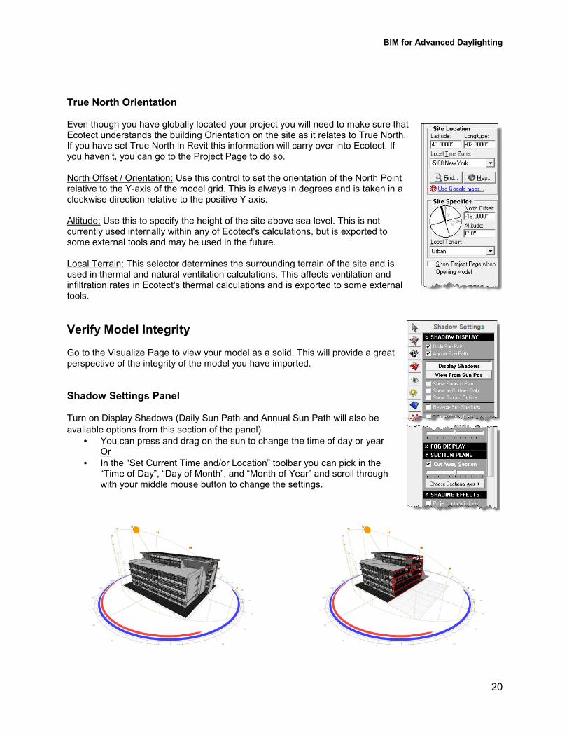
True North Orientation Even though you have globally located your project you will need to make sure that Ecotect understands the building Orientation on the site as it relates to True North. If you have set True North in Revit this information will carry over into Ecotect. If you haven’t, you can go to the Project Page to do so. North Offset / Orientation: Use this control to set the orientation of the North Point relative to the Y3axis of the model grid. This is always in degrees and is taken in a clockwise direction relative to the positive Y axis. Altitude: Use this to specify the height of the site above sea level. This is not currently used internally within any of Ecotect's calculations, but is exported to some external tools and may be used in the future. Local Terrain: This selector determines the surrounding terrain of the site and is used in thermal and natural ventilation calculations. This affects ventilation and infiltration rates in Ecotect's thermal calculations and is exported to some external tools.
Verify Model Integrity Go to the Visualize Page to view your model as a solid. This will provide a great perspective of the integrity of the model you have imported.
Shadow Settings Panel Turn on Display Shadows (Daily Sun Path and Annual Sun Path will also be
available options from this section of the panel).
• You can press and drag on the sun to change the time of day or year Or
• In the “Set Current Time and/or Location” toolbar you can pick in the “Time of Day”, “Day of Month”, and “Month of Year” and scroll through with your middle mouse button to change the settings.

BIM for Advanced Daylighting
21
Analysis Methods & Material Assignments Ecotect Lighting Analysis or Export Model Data to Radiance? Following the definition of your model geometry and the weather/location data you input in Ecotect Analysis the material assignments and analysis methods you choose will be the single biggest item you need to address in your process. There are two different workflows that you can define for how to capture a natural daylight levels in your model. One is to utilize the Lighting Analysis tools in Ecotect or you can decide to leverage Export Model Data to Radiance option to run the simulation. If you choose to run the Ecotect Lighting Analysis it is important to understand how the simulation is being run. The daylight illuminance levels in this analysis are not date or time dependant 3 they represent worst3case design conditions based on an 'average' cloudy or uniform sky distribution in mid3winter. Additionally, there can be a significant time difference in how much longer it takes a lighting analysis to run in Ecotect as compared to Radiance. If we’re looking to design around a specific date/time condition or quantity data for the LEED IEQc8.1 documentation requirements this will not provide the needed feedback. For this you will want to leverage the “Export Model DataS” to Radiance function of Ecotect. This will allow you to take advantage of Radiance as a free radiosity3based physically accurate lighting simulation tool to address quantitative and qualitative daylighting issues. While there is a value to running your simulation using the CIE Overcast Sky Condition in Ecotect, you should be aware that you can also run your Radiance simulation with this Sky Condition along with a series of others. Additionally, the Radiance simulation will allow you to have more consistent results since each analysis will be utilizing the same material properties. Once the needed analysis methodology is established, materials should be considered next.
Material Assignments Analysis Outcomes When the individual 3DS files were imported into Ecotect, general material categories were set by element type (Set as Wall, Set as FloorS). Next we need to focus on the specific properties of each material that will control how daylight is being dealt with during the analysis. Depending on what stage your design is in you may or may not know the exact properties of the construction materials in your project. If this is the case and you are trying to run some early general illuminance studies, the industry provides some basic rules of thumb to guide this early design process simulations. Rules of thumb for material reflectance:
• 80% – Ceilings
• 60% – Walls
• 20% – Floors When looking to provide documentation in support of LEED credit (LEED IEQc8.1: Daylight and Views – Daylight) you can look at the LEED Reference Guide for insight. In the calculation section of the text for “Option 1. Simulation" in LEED IEQc8.1 the reference manual states that “the model should include glazing properties, as well as representative surface reflectance settings for interior finishes.”
BIM for Advanced Daylighting
22
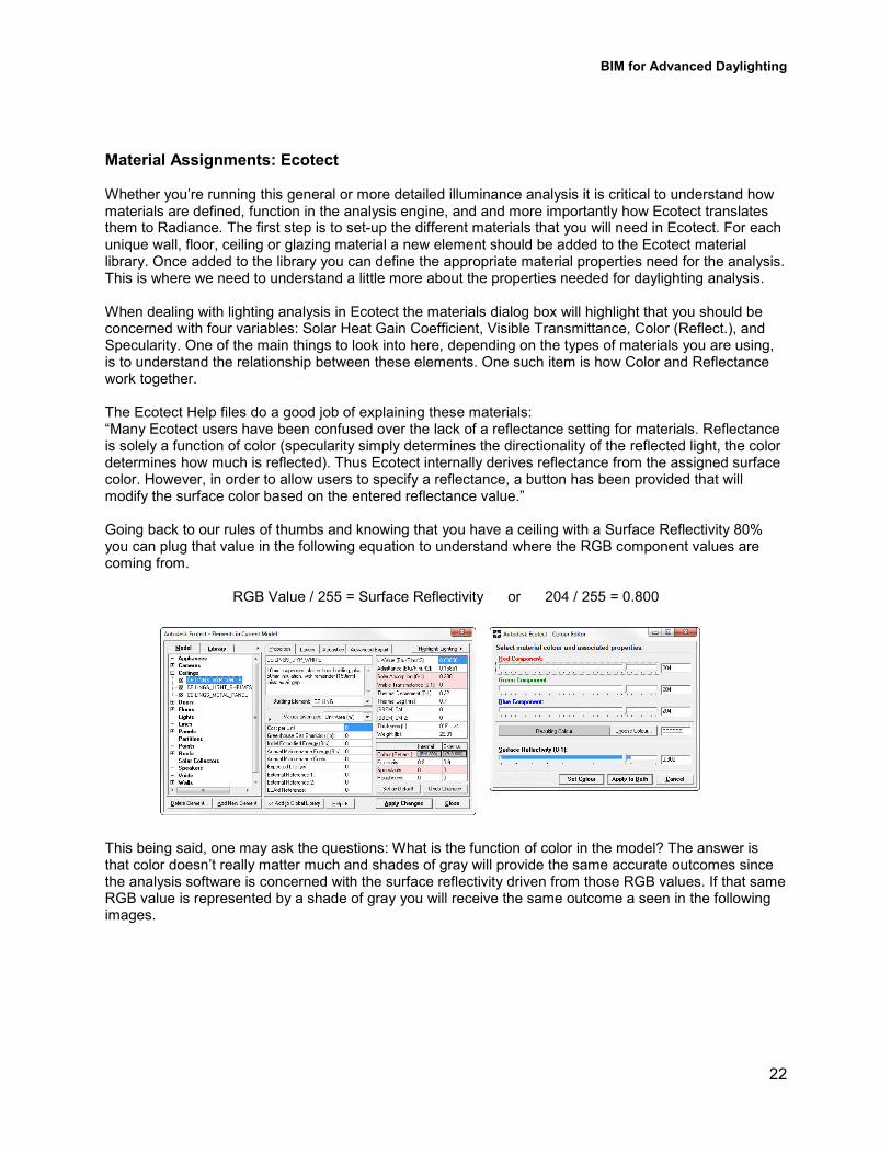
Material Assignments: Ecotect Whether you’re running this general or more detailed illuminance analysis it is critical to understand how materials are defined, function in the analysis engine, and and more importantly how Ecotect translates them to Radiance. The first step is to set3up the different materials that you will need in Ecotect. For each unique wall, floor, ceiling or glazing material a new element should be added to the Ecotect material library. Once added to the library you can define the appropriate material properties need for the analysis. This is where we need to understand a little more about the properties needed for daylighting analysis. When dealing with lighting analysis in Ecotect the materials dialog box will highlight that you should be concerned with four variables: Solar Heat Gain Coefficient, Visible Transmittance, Color (Reflect.), and Specularity. One of the main things to look into here, depending on the types of materials you are using, is to understand the relationship between these elements. One such item is how Color and Reflectance work together. The Ecotect Help files do a good job of explaining these materials: “Many Ecotect users have been confused over the lack of a reflectance setting for materials. Reflectance is solely a function of color (specularity simply determines the directionality of the reflected light, the color determines how much is reflected). Thus Ecotect internally derives reflectance from the assigned surface color. However, in order to allow users to specify a reflectance, a button has been provided that will modify the surface color based on the entered reflectance value.” Going back to our rules of thumbs and knowing that you have a ceiling with a Surface Reflectivity 80% you can plug that value in the following equation to understand where the RGB component values are coming from.
RGB Value / 255 = Surface Reflectivity or 204 / 255 = 0.800 This being said, one may ask the questions: What is the function of color in the model? The answer is that color doesn’t really matter much and shades of gray will provide the same accurate outcomes since the analysis software is concerned with the surface reflectivity driven from those RGB values. If that same RGB value is represented by a shade of gray you will receive the same outcome a seen in the following images.
BIM for Advanced Daylighting
23
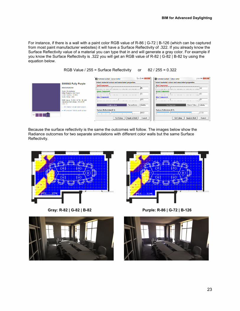
For instance, if there is a wall with a paint color RGB value of R386 | G372 | B3126 (which can be captured from most paint manufacturer websites) it will have a Surface Reflectivity of .322. If you already know the Surface Reflectivity value of a material you can type that in and will generate a gray color. For example if you know the Surface Reflectivity is .322 you will get an RGB value of R382 | G382 | B382 by using the equation below.
RGB Value / 255 = Surface Reflectivity or 82 / 255 = 0.322
Because the surface reflectivity is the same the outcomes will follow. The images below show the Radiance outcomes for two separate simulations with different color walls but the same Surface Reflectivity.
Gray: R�82 | G�82 | B�82 Purple: R�86 | G�72 | B�126
BIM for Advanced Daylighting
24
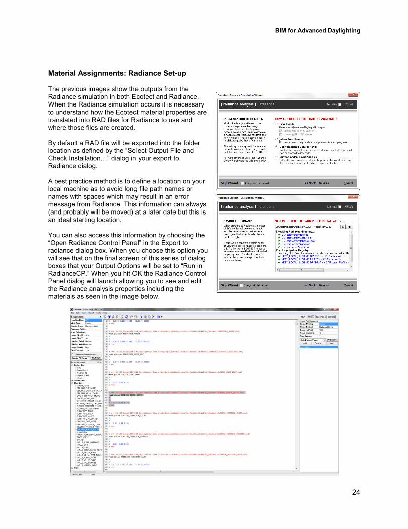
Material Assignments: Radiance Set�up The previous images show the outputs from the Radiance simulation in both Ecotect and Radiance. When the Radiance simulation occurs it is necessary to understand how the Ecotect material properties are translated into RAD files for Radiance to use and where those files are created. By default a RAD file will be exported into the folder location as defined by the “Select Output File and Check InstallationS” dialog in your export to Radiance dialog. A best practice method is to define a location on your local machine as to avoid long file path names or names with spaces which may result in an error message from Radiance. This information can always (and probably will be moved) at a later date but this is an ideal starting location. You can also access this information by choosing the “Open Radiance Control Panel” in the Export to radiance dialog box. When you choose this option you will see that on the final screen of this series of dialog boxes that your Output Options will be set to “Run in RadianceCP.” When you hit OK the Radiance Control Panel dialog will launch allowing you to see and edit the Radiance analysis properties including the materials as seen in the image below.
BIM for Advanced Daylighting
25
Material Assignments: Radiance Material Definitions
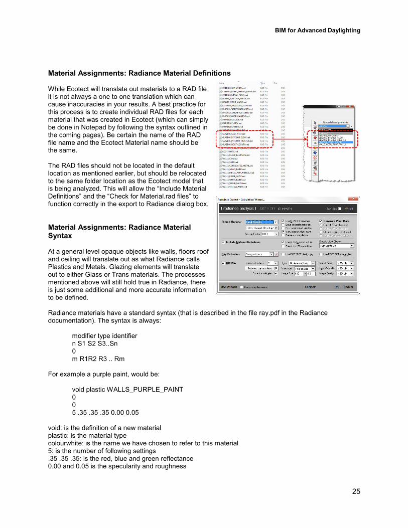
While Ecotect will translate out materials to a RAD file it is not always a one to one translation which can cause inaccuracies in your results. A best practice for this process is to create individual RAD files for each material that was created in Ecotect (which can simply be done in Notepad by following the syntax outlined in the coming pages). Be certain the name of the RAD file name and the Ecotect Material name should be the same. The RAD files should not be located in the default location as mentioned earlier, but should be relocated to the same folder location as the Ecotect model that is being analyzed. This will allow the “Include Material Definitions” and the “Check for Material.rad files” to function correctly in the export to Radiance dialog box.
Material Assignments: Radiance Material Syntax
At a general level opaque objects like walls, floors roof and ceiling will translate out as what Radiance calls Plastics and Metals. Glazing elements will translate out to either Glass or Trans materials. The processes mentioned above will still hold true in Radiance, there is just some additional and more accurate information to be defined. Radiance materials have a standard syntax (that is described in the file ray.pdf in the Radiance documentation). The syntax is always:
modifier type identifier n S1 S2 S3..Sn 0 m R1R2 R3 .. Rm
For example a purple paint, would be: void plastic WALLS_PURPLE_PAINT 0 0 5 .35 .35 .35 0.00 0.05
void: is the definition of a new material plastic: is the material type colourwhite: is the name we have chosen to refer to this material 5: is the number of following settings .35 .35 .35: is the red, blue and green reflectance 0.00 and 0.05 is the specularity and roughness
BIM for Advanced Daylighting
26
Plastic is a material with uncolored highlights. It is given by its RGB reflectance, its fraction of specularity, and its roughness value. Roughness is specified as the rms slope of surface facets. A value of 0 corresponds to a perfectly smooth surface, and a value of 1 would be a very rough surface. Specularity fractions greater than 0.1 and roughness values greater than 0.2 are not very realistic. (A pattern modifying plastic will affect the material color).
mod plastic id 0 0 5 red green blue spec rough
Metal is similar to plastic, but specular highlights are modified by the material color. Specularity of metals is usually .9 or greater. As for plastic, roughness values above .2 are uncommon. Glass is similar to dielectric, but it is optimized for thin glass surfaces (n = 1.52). One transmitted ray and one reflected ray is produced. By using a single surface is in place of two, internal reflections are avoided. The surface orientation is irrelevant, as it is for plastic, metal, and trans. The only specification required is the transmissivity at normal incidence. (Transmissivity is the amount of light not absorbed in one traversal of the material. Transmittance 33 the value usually measured 33 is the total light transmitted through the pane including multiple reflections). To compute transmissivity (tn) from transmittance (Tn) use:
tn = (sqrt (.8402528435 + .0072522239 * Tn * Tn) 3 .9166530661) / .0036261119 / Tn Standard 88% transmittance glass has a transmissivity of 0.96. (A pattern modifying glass will affect the transmissivity.) If a fourth real argument is given, it is interpreted as the index of refraction to use instead of 1.52.
mod glass id 0 0 3 rtn gtn btn
For example a glazing system with a 70% transmittance glass would incorrectly translate out of Ecotect (example on left) and should more accurate be dealt with as a RAD material file (example on right).
void glass GLAZING_NORTH_SOUTH void glass GLAZING_NORTH_SOUTH 0 0 0 0 3 0.697 0.763 0.763 3 0.763 0.763 0.763
Trans is a translucent material, similar to plastic. The transmissivity is the fraction of penetrating light that travels all the way through the material. The transmitted specular component is the fraction of transmitted light that is not diffusely scattered. Transmitted and diffusely reflected light is modified by the material color. Translucent objects are infinitely thin.
mod trans id 0 0 7 red green blue spec rough trans tspec
Material Assignments: Apply Materials To apply the specific material that has been created you should be in the 3D Editor Page.
• Go to the Zone Management Panel
• Right click on a zone in the model (i.e. Floor_Carpet.3DS)
• Right Click and choose “Select Objects On”
• Next go to the Material Assignments Panel
• Select the appropriate material from the (i.e. FLOORS_CARPET_DARK_GREY)
• Select Apply Changes
LEED IEQc8.1: Daylight and Vie With all major model components defined it is important to look back at the LEED Reference Guide to define the remaining criteria for calculating daylight Option 1. Simulation
• Create a daylight simulation model for the buiinclude glazing properties, as well as representative surface reffinishes.
• For each applicable area, include a horizontal calculation grid at 30 inches above the floor, or measured at the appropriate desk or work height level for the intended use of the space. Thisrepresents the typical work plane height. It is recommended that with a regular size interval so that the grid has at least 9 measurimaximum interval of 53feet to provide a detailed illumination diagram for each room.
• Calculate the daylight illumination for each applicable space using the following daylight clear3sky conditions at both 9:00 a.m. geographic location.
• Identify the area of the room that has daylight illumination between 10 footcandles and footcandles at both times (9:00 am and 3:00 pm). Spaces that do not meet the daylillumination levels at both times do not qualify.
• If the space uses automated view preserving shades, the maximum footcandle requirement does not apply.
• Sum the square footage of all daylighted rooms or areas and divide by the total square footage of all applicable spaces.
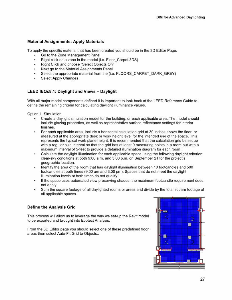
Define the Analysis Grid This process will allow us to leverage the way we setto be exported and brought into Ecotect Analysis. From the 3D Editor page you should select one of these predefined floor areas then select Auto3Fit Grid to Objects..
BIM for Advanced Daylighting
Material Assignments: Apply Materials
To apply the specific material that has been created you should be in the 3D Editor Page.
Go to the Zone Management Panel
one in the model (i.e. Floor_Carpet.3DS)
Right Click and choose “Select Objects On”
go to the Material Assignments Panel
Select the appropriate material from the (i.e. FLOORS_CARPET_DARK_GREY)
LEED IEQc8.1: Daylight and Views – Daylight
defined it is important to look back at the LEED Reference Guide to calculating daylight illuminance values.
Create a daylight simulation model for the building, or each applicable area. The model shouldinclude glazing properties, as well as representative surface reflectance settings for interior
For each applicable area, include a horizontal calculation grid at 30 inches above the floor, or sured at the appropriate desk or work height level for the intended use of the space. This
represents the typical work plane height. It is recommended that the calculation grid be set up with a regular size interval so that the grid has at least 9 measuring points in a room but with a
feet to provide a detailed illumination diagram for each room.
Calculate the daylight illumination for each applicable space using the following daylight sky conditions at both 9:00 a.m. and 3:00 p.m. on September 21 for the project’s
Identify the area of the room that has daylight illumination between 10 footcandles and footcandles at both times (9:00 am and 3:00 pm). Spaces that do not meet the dayl
ion levels at both times do not qualify.
If the space uses automated view preserving shades, the maximum footcandle requirement does
Sum the square footage of all daylighted rooms or areas and divide by the total square footage of
This process will allow us to leverage the way we set3up the Revit model to be exported and brought into Ecotect Analysis.
From the 3D Editor page you should select one of these predefined floor Fit Grid to Objects..
BIM for Advanced Daylighting
27
To apply the specific material that has been created you should be in the 3D Editor Page.
Select the appropriate material from the (i.e. FLOORS_CARPET_DARK_GREY)
defined it is important to look back at the LEED Reference Guide to
lding, or each applicable area. The model should lectance settings for interior
For each applicable area, include a horizontal calculation grid at 30 inches above the floor, or sured at the appropriate desk or work height level for the intended use of the space. This
the calculation grid be set up g points in a room but with a
feet to provide a detailed illumination diagram for each room.
Calculate the daylight illumination for each applicable space using the following daylight criterion: 0 p.m. on September 21 for the project’s
Identify the area of the room that has daylight illumination between 10 footcandles and 500 footcandles at both times (9:00 am and 3:00 pm). Spaces that do not meet the daylight
If the space uses automated view preserving shades, the maximum footcandle requirement does
Sum the square footage of all daylighted rooms or areas and divide by the total square footage of
BIM for Advanced Daylighting
28
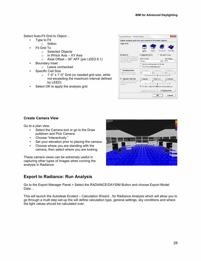
Select Auto3Fit Grid to ObjectS
• Type to Fit o Within
• Fit Grid To o Selected Objects o In Which Axis – XY Axis o Axial Offset – 30” AFF (per LEED 8.1)
• Boundary Inset o Leave unchecked
• Specific Cell Size o 1’30” x 1’30” Grid (or needed grid size, while
not exceeding the maximum interval defined by LEED)
• Select OK to apply the analysis grid
Create Camera View
Go to a plan view.
• Select the Camera tool or go to the Draw pulldown and Pick Camera
• Choose “Interactively.”
• Set your elevation prior to placing the camera.
• Choose where you are standing with the camera, then select where you are looking.
These camera views can be extremely useful in capturing other types of images when running the analysis in Radiance.
Export to Radiance: Run Analysis Go to the Export Manager Panel > Select the RADIANCE/DAYSIM Button and choose Export Model DataS This will launch the Autodesk Ecotect – Calculation WizardSfor Radiance Analysis which will allow you to go through a multi step set3up the will define calculation type, general settings, sky conditions and where the light values should be calculated over.
BIM for Advanced Daylighting
29
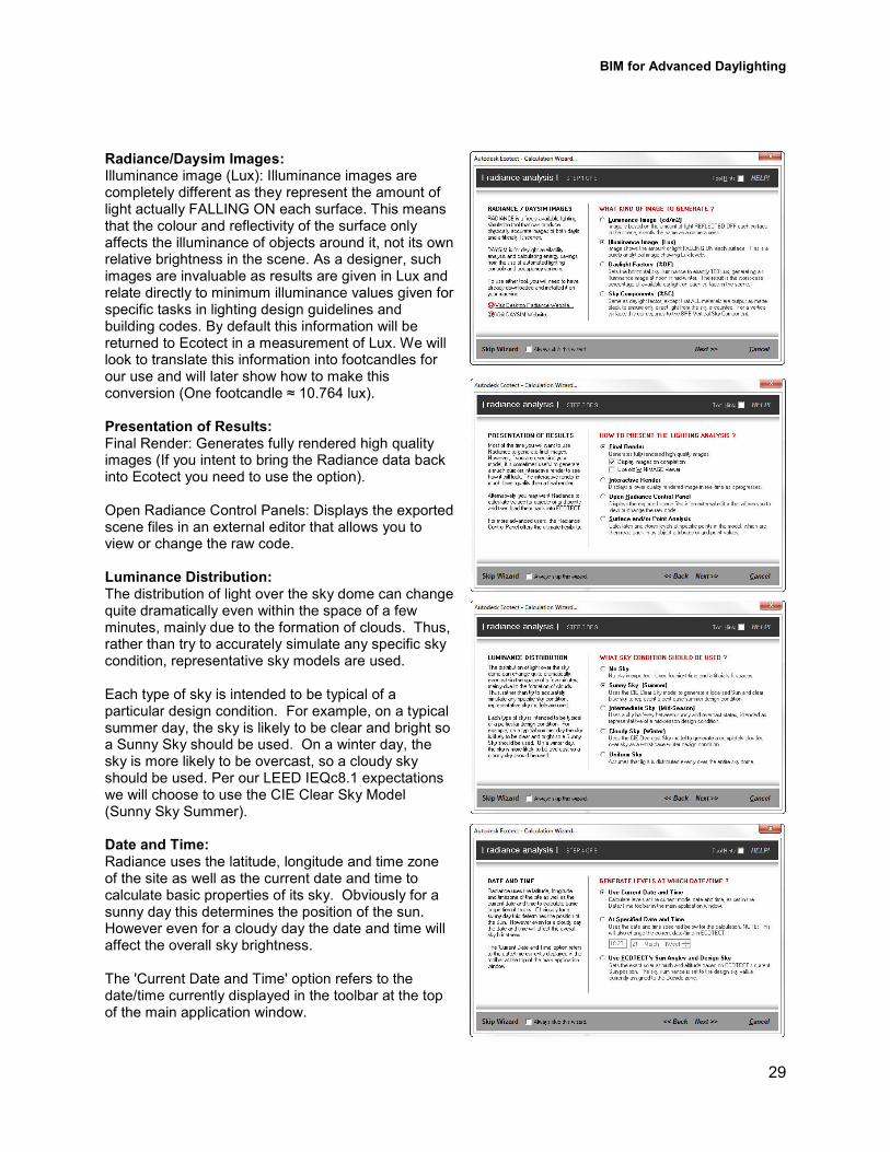
Radiance/Daysim Images: Illuminance image (Lux): Illuminance images are completely different as they represent the amount of light actually FALLING ON each surface. This means that the colour and reflectivity of the surface only affects the illuminance of objects around it, not its own relative brightness in the scene. As a designer, such images are invaluable as results are given in Lux and relate directly to minimum illuminance values given for specific tasks in lighting design guidelines and building codes. By default this information will be returned to Ecotect in a measurement of Lux. We will look to translate this information into footcandles for our use and will later show how to make this conversion (One footcandle ≈ 10.764 lux). Presentation of Results: Final Render: Generates fully rendered high quality images (If you intent to bring the Radiance data back into Ecotect you need to use the option). Open Radiance Control Panels: Displays the exported scene files in an external editor that allows you to view or change the raw code. Luminance Distribution: The distribution of light over the sky dome can change quite dramatically even within the space of a few minutes, mainly due to the formation of clouds. Thus, rather than try to accurately simulate any specific sky condition, representative sky models are used. Each type of sky is intended to be typical of a particular design condition. For example, on a typical summer day, the sky is likely to be clear and bright so a Sunny Sky should be used. On a winter day, the sky is more likely to be overcast, so a cloudy sky should be used. Per our LEED IEQc8.1 expectations we will choose to use the CIE Clear Sky Model (Sunny Sky Summer). Date and Time: Radiance uses the latitude, longitude and time zone of the site as well as the current date and time to calculate basic properties of its sky. Obviously for a sunny day this determines the position of the sun. However even for a cloudy day the date and time will affect the overall sky brightness. The 'Current Date and Time' option refers to the date/time currently displayed in the toolbar at the top of the main application window.
BIM for Advanced Daylighting
30
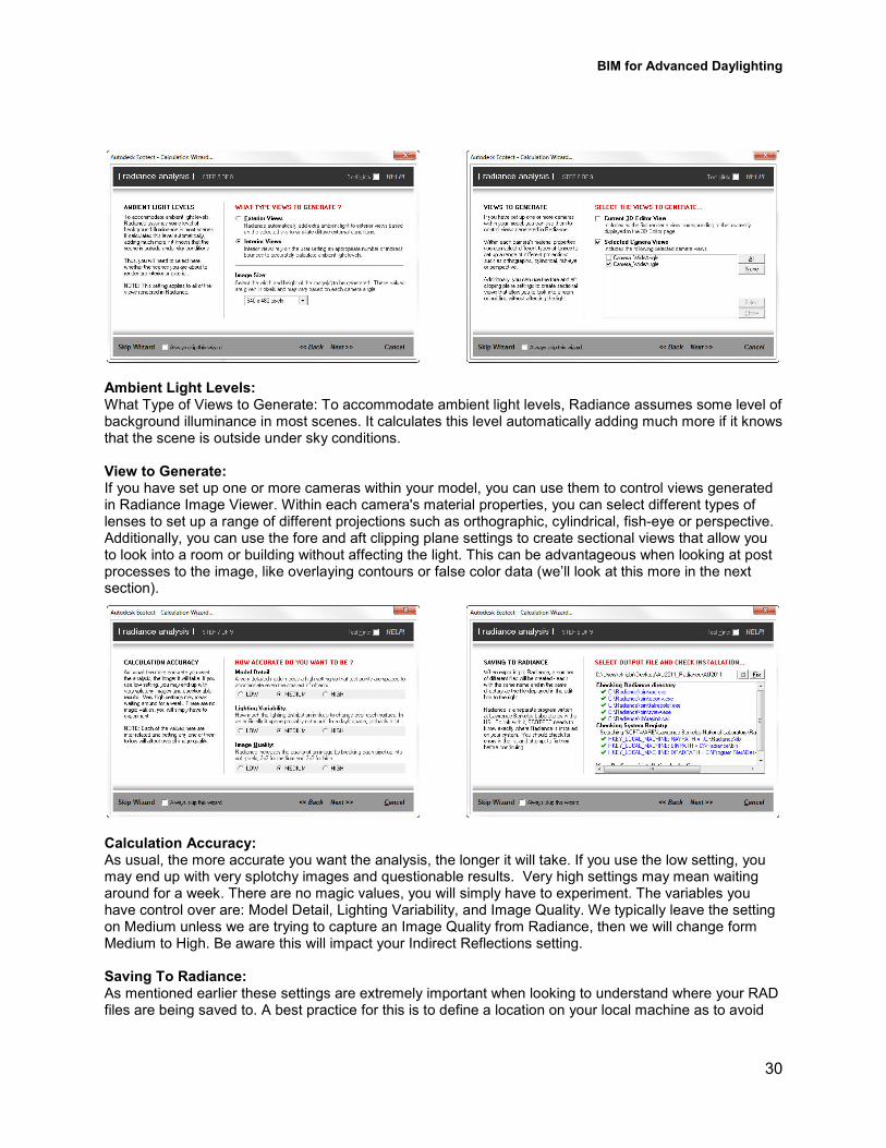
Ambient Light Levels: What Type of Views to Generate: To accommodate ambient light levels, Radiance assumes some level of background illuminance in most scenes. It calculates this level automatically adding much more if it knows that the scene is outside under sky conditions. View to Generate: If you have set up one or more cameras within your model, you can use them to control views generated in Radiance Image Viewer. Within each camera's material properties, you can select different types of lenses to set up a range of different projections such as orthographic, cylindrical, fish3eye or perspective. Additionally, you can use the fore and aft clipping plane settings to create sectional views that allow you to look into a room or building without affecting the light. This can be advantageous when looking at post processes to the image, like overlaying contours or false color data (we’ll look at this more in the next section).
Calculation Accuracy: As usual, the more accurate you want the analysis, the longer it will take. If you use the low setting, you may end up with very splotchy images and questionable results. Very high settings may mean waiting around for a week. There are no magic values, you will simply have to experiment. The variables you have control over are: Model Detail, Lighting Variability, and Image Quality. We typically leave the setting on Medium unless we are trying to capture an Image Quality from Radiance, then we will change form Medium to High. Be aware this will impact your Indirect Reflections setting. Saving To Radiance: As mentioned earlier these settings are extremely important when looking to understand where your RAD files are being saved to. A best practice for this is to define a location on your local machine as to avoid
BIM for Advanced Daylighting
31
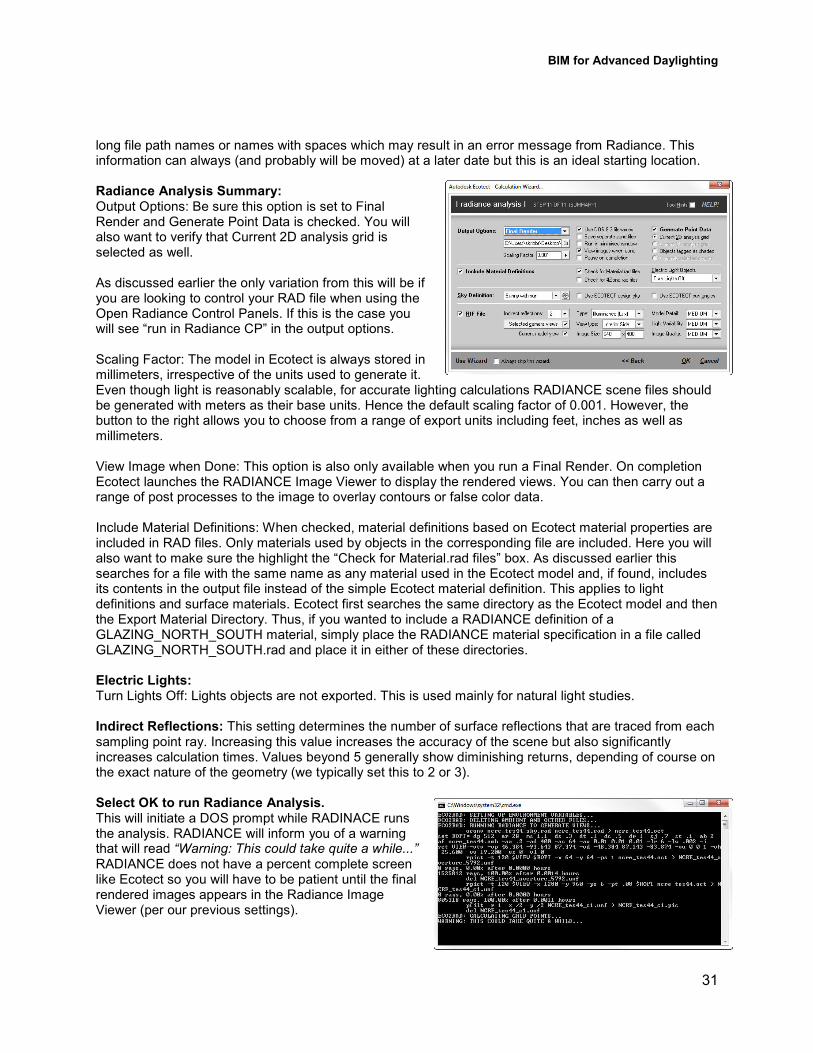
long file path names or names with spaces which may result in an error message from Radiance. This information can always (and probably will be moved) at a later date but this is an ideal starting location. Radiance Analysis Summary: Output Options: Be sure this option is set to Final Render and Generate Point Data is checked. You will also want to verify that Current 2D analysis grid is selected as well. As discussed earlier the only variation from this will be if you are looking to control your RAD file when using the Open Radiance Control Panels. If this is the case you will see “run in Radiance CP” in the output options. Scaling Factor: The model in Ecotect is always stored in millimeters, irrespective of the units used to generate it. Even though light is reasonably scalable, for accurate lighting calculations RADIANCE scene files should be generated with meters as their base units. Hence the default scaling factor of 0.001. However, the button to the right allows you to choose from a range of export units including feet, inches as well as millimeters. View Image when Done: This option is also only available when you run a Final Render. On completion Ecotect launches the RADIANCE Image Viewer to display the rendered views. You can then carry out a range of post processes to the image to overlay contours or false color data. Include Material Definitions: When checked, material definitions based on Ecotect material properties are included in RAD files. Only materials used by objects in the corresponding file are included. Here you will also want to make sure the highlight the “Check for Material.rad files” box. As discussed earlier this searches for a file with the same name as any material used in the Ecotect model and, if found, includes its contents in the output file instead of the simple Ecotect material definition. This applies to light definitions and surface materials. Ecotect first searches the same directory as the Ecotect model and then the Export Material Directory. Thus, if you wanted to include a RADIANCE definition of a GLAZING_NORTH_SOUTH material, simply place the RADIANCE material specification in a file called GLAZING_NORTH_SOUTH.rad and place it in either of these directories. Electric Lights: Turn Lights Off: Lights objects are not exported. This is used mainly for natural light studies. Indirect Reflections: This setting determines the number of surface reflections that are traced from each sampling point ray. Increasing this value increases the accuracy of the scene but also significantly increases calculation times. Values beyond 5 generally show diminishing returns, depending of course on the exact nature of the geometry (we typically set this to 2 or 3). Select OK to run Radiance Analysis. This will initiate a DOS prompt while RADINACE runs the analysis. RADIANCE will inform you of a warning that will read “Warning: This could take quite a while...” RADIANCE does not have a percent complete screen like Ecotect so you will have to be patient until the final rendered images appears in the Radiance Image Viewer (per our previous settings).
BIM for Advanced Daylighting
32
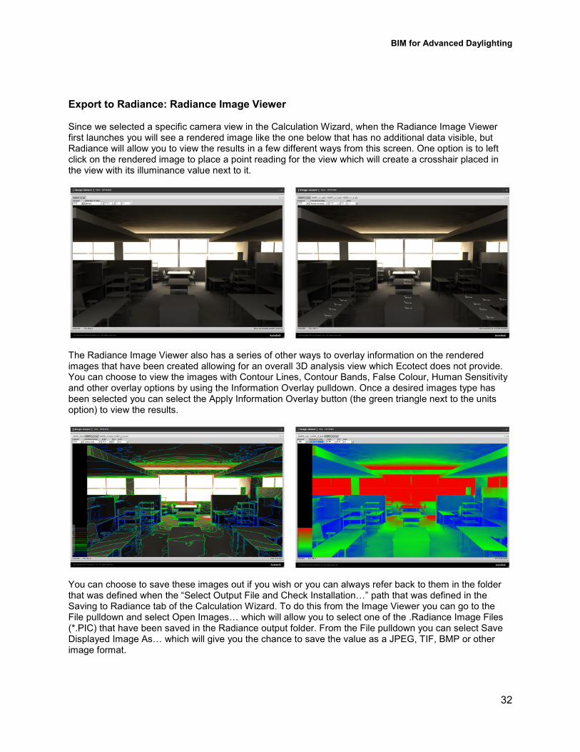
Export to Radiance: Radiance Image Viewer Since we selected a specific camera view in the Calculation Wizard, when the Radiance Image Viewer first launches you will see a rendered image like the one below that has no additional data visible, but Radiance will allow you to view the results in a few different ways from this screen. One option is to left click on the rendered image to place a point reading for the view which will create a crosshair placed in the view with its illuminance value next to it.
The Radiance Image Viewer also has a series of other ways to overlay information on the rendered images that have been created allowing for an overall 3D analysis view which Ecotect does not provide. You can choose to view the images with Contour Lines, Contour Bands, False Colour, Human Sensitivity and other overlay options by using the Information Overlay pulldown. Once a desired images type has been selected you can select the Apply Information Overlay button (the green triangle next to the units option) to view the results.
You can choose to save these images out if you wish or you can always refer back to them in the folder that was defined when the “Select Output File and Check InstallationS” path that was defined in the Saving to Radiance tab of the Calculation Wizard. To do this from the Image Viewer you can go to the File pulldown and select Open ImagesS which will allow you to select one of the .Radiance Image Files (*.PIC) that have been saved in the Radiance output folder. From the File pulldown you can select Save Displayed Image AsS which will give you the chance to save the value as a JPEG, TIF, BMP or other image format.
BIM for Advanced Daylighting
33
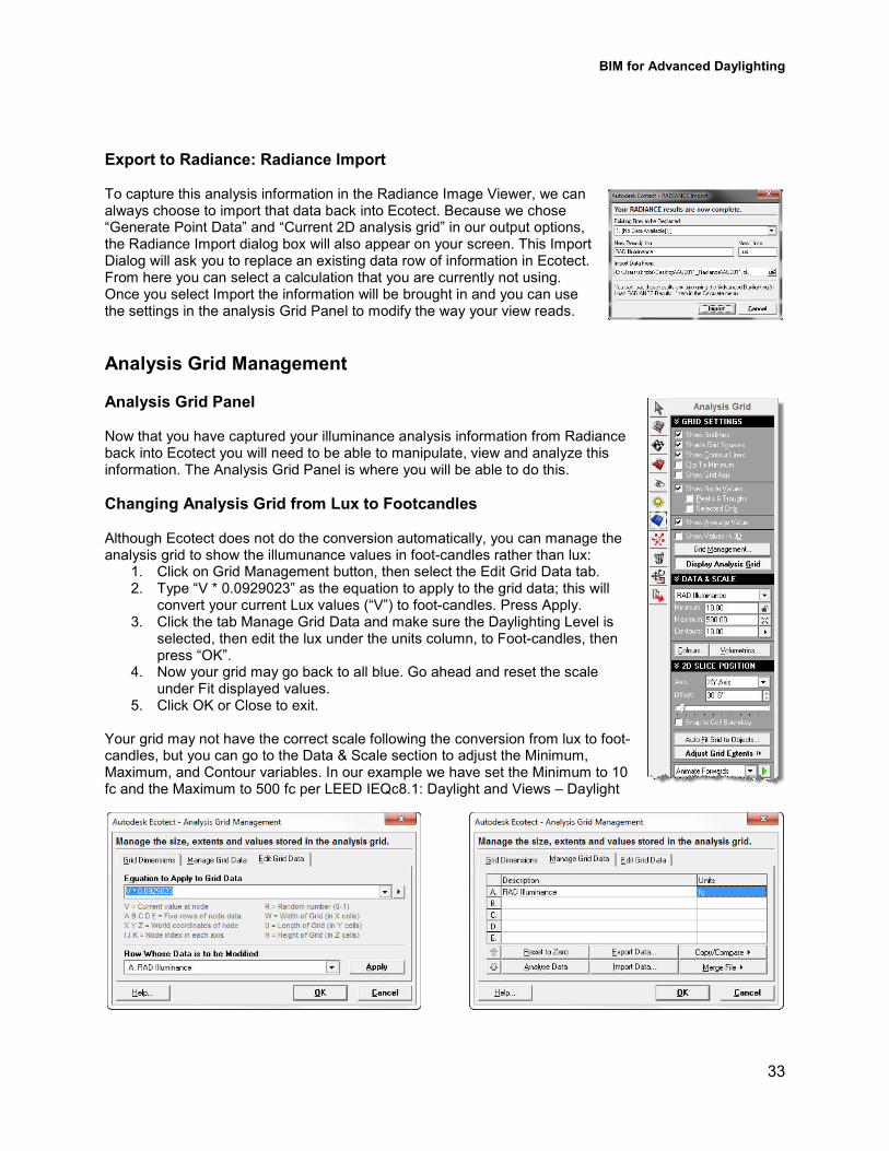
Export to Radiance: Radiance Import To capture this analysis information in the Radiance Image Viewer, we can always choose to import that data back into Ecotect. Because we chose “Generate Point Data” and “Current 2D analysis grid” in our output options, the Radiance Import dialog box will also appear on your screen. This Import Dialog will ask you to replace an existing data row of information in Ecotect. From here you can select a calculation that you are currently not using. Once you select Import the information will be brought in and you can use the settings in the analysis Grid Panel to modify the way your view reads.
Analysis Grid Management Analysis Grid Panel Now that you have captured your illuminance analysis information from Radiance back into Ecotect you will need to be able to manipulate, view and analyze this information. The Analysis Grid Panel is where you will be able to do this.
Changing Analysis Grid from Lux to Footcandles
Although Ecotect does not do the conversion automatically, you can manage the analysis grid to show the illumunance values in foot3candles rather than lux:
1. Click on Grid Management button, then select the Edit Grid Data tab. 2. Type “V * 0.0929023” as the equation to apply to the grid data; this will
convert your current Lux values (“V”) to foot3candles. Press Apply. 3. Click the tab Manage Grid Data and make sure the Daylighting Level is
selected, then edit the lux under the units column, to Foot3candles, then press “OK”.
4. Now your grid may go back to all blue. Go ahead and reset the scale under Fit displayed values.
5. Click OK or Close to exit. Your grid may not have the correct scale following the conversion from lux to foot3candles, but you can go to the Data & Scale section to adjust the Minimum, Maximum, and Contour variables. In our example we have set the Minimum to 10 fc and the Maximum to 500 fc per LEED IEQc8.1: Daylight and Views – Daylight
BIM for Advanced Daylighting
34
Another option of capturing information from Radiance is to save the analysis grid information for future use which can save a significant amount of time if you don’t have to re3run the simulations. To do this Ecotect gives the opportunity to both Export and Import the analysis grid information.
Import and/or Export Analysis Grid Data:
• Select Grid Management from the Analysis Grid Panel
• Go to the Manage Grid Data tab
• Select Export DataSwhich will save out a .txt file of the results
• You can always go back and choose Import DataS
• Select a previously exported .txt file to display on the analysis grid
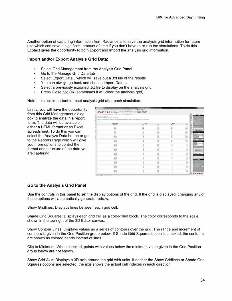
• Press Close not OK (sometimes it will clear the analysis grid) Note: It is also important to reset analysis grid after each simulation. Lastly, you will have the opportunity from this Grid Management dialog box to analyze the data in a report form. The data will be available in either a HTML format or an Excel spreadsheet. To do this you can select the Analyze Data button or go to the Reports Page which will give you more options to control the format and structure of the data you are capturing.
Go to the Analysis Grid Panel Use the controls in this panel to set the display options of the grid. If the grid is displayed, changing any of these options will automatically generate redraw. Show Gridlines: Displays lines between each grid cell. Shade Grid Squares: Displays each grid cell as a color3filled block. The color corresponds to the scale shown in the top3right of the 3D Editor canvas. Show Contour Lines: Displays values as a series of contours over the grid. The range and increment of contours is given in the Grid Position group below. If Shade Grid Squares option is checked, the contours are shown as colored bands instead of lines. Clip to Minimum: When checked, points with values below the minimum value given in the Grid Position group below are not shown. Show Grid Axis: Displays a 3D axis around the grid with units. If neither the Show Gridlines or Shade Grid Squares options are selected, the axis shows the actual cell indexes in each direction.
BIM for Advanced Daylighting
35
Show Node Values: Displays the numeric value currently stored at each grid node.
• Peaks & Troughs: Displays the value at a grid node when all surrounding points are either higher or lower. On a relatively smooth grid this usually gives a clearer view than showing all node values.
• Selected Only: Displays values only at grid points that are currently selected. See the Grid Nodes group for details on actually selecting individual nodes. This setting allows you to specifically choose the exact nodes at which point values will be displayed.
Show Average Value: When checked, the average grid value is displayed in the bottom3left corner of the 3D Editor canvas. This is simply the sum of all visible node values divided by the number of nodes summed. Show Values in 3D: Displays each point value with an offset based on its value and the current scale. This produces an undulating grid surface as opposed to a flat plane.
Data Output Options:
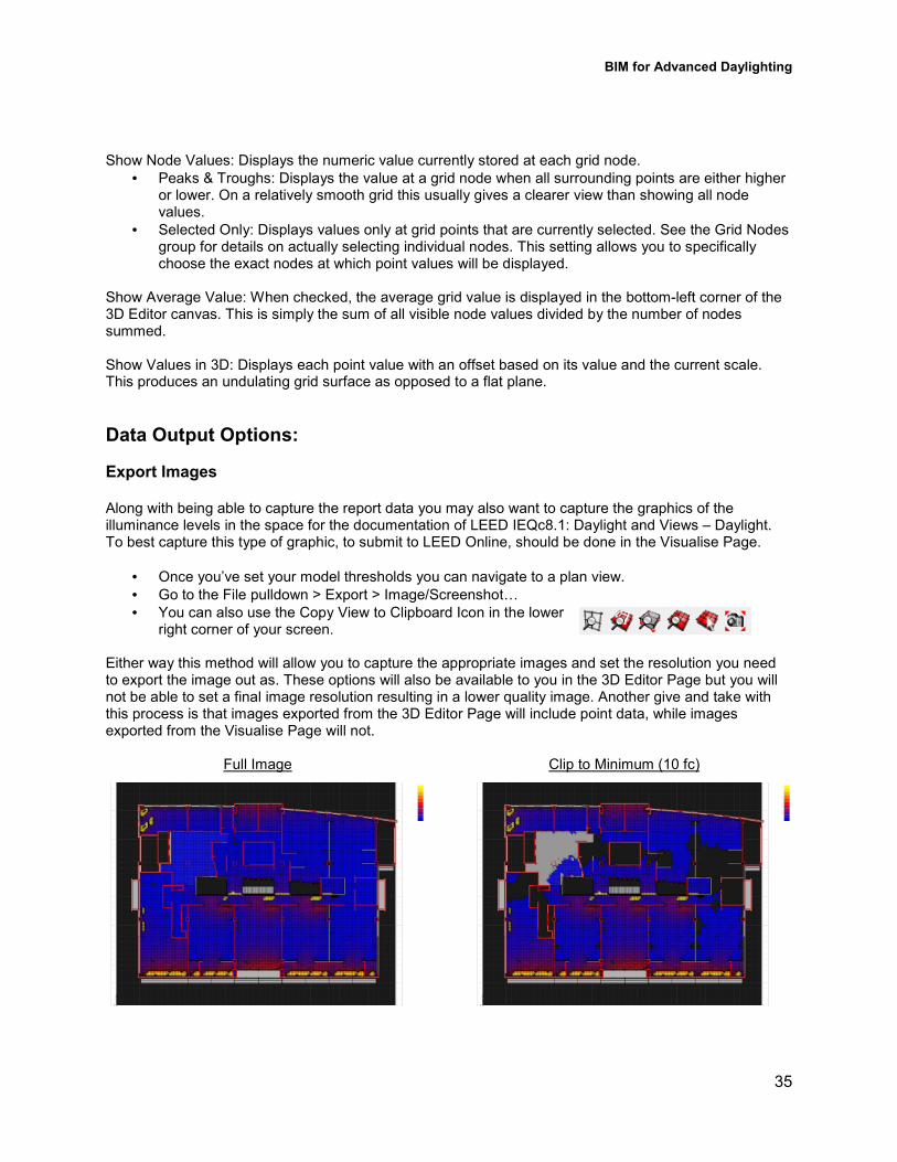
Export Images Along with being able to capture the report data you may also want to capture the graphics of the illuminance levels in the space for the documentation of LEED IEQc8.1: Daylight and Views – Daylight. To best capture this type of graphic, to submit to LEED Online, should be done in the Visualise Page.
• Once you’ve set your model thresholds you can navigate to a plan view.
• Go to the File pulldown > Export > Image/ScreenshotS
• You can also use the Copy View to Clipboard Icon in the lower right corner of your screen.
Either way this method will allow you to capture the appropriate images and set the resolution you need to export the image out as. These options will also be available to you in the 3D Editor Page but you will not be able to set a final image resolution resulting in a lower quality image. Another give and take with this process is that images exported from the 3D Editor Page will include point data, while images exported from the Visualise Page will not.
Full Image Clip to Minimum (10 fc)
BIM for Advanced Daylighting
36
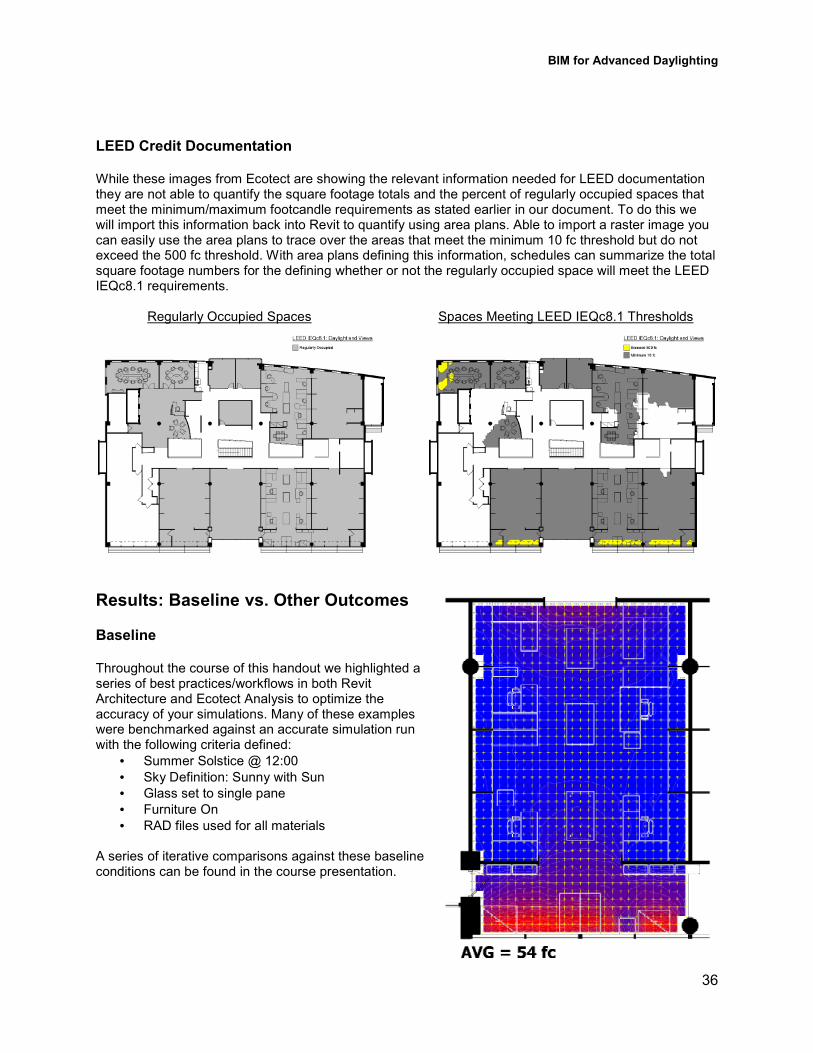
LEED Credit Documentation While these images from Ecotect are showing the relevant information needed for LEED documentation they are not able to quantify the square footage totals and the percent of regularly occupied spaces that meet the minimum/maximum footcandle requirements as stated earlier in our document. To do this we will import this information back into Revit to quantify using area plans. Able to import a raster image you can easily use the area plans to trace over the areas that meet the minimum 10 fc threshold but do not exceed the 500 fc threshold. With area plans defining this information, schedules can summarize the total square footage numbers for the defining whether or not the regularly occupied space will meet the LEED IEQc8.1 requirements.
Regularly Occupied Spaces Spaces Meeting LEED IEQc8.1 Thresholds
Results: Baseline vs. Other Outcomes Baseline Throughout the course of this handout we highlighted a series of best practices/workflows in both Revit Architecture and Ecotect Analysis to optimize the accuracy of your simulations. Many of these examples were benchmarked against an accurate simulation run with the following criteria defined:
• Summer Solstice @ 12:00
• Sky Definition: Sunny with Sun
• Glass set to single pane
• Furniture On
• RAD files used for all materials A series of iterative comparisons against these baseline conditions can be found in the course presentation.
BIM for Advanced Daylighting
37
It is also important to keep in mind that while daylighting is complex there are a couple key items you should keep in mind when referring back to this handout and others from the Existing Building Power Track at Autodesk University 2011:
• Daylighting is complex o Understand your BIM workflow to optimize the interoperability of the geometry you create o You need to leverage both Ecotect Analysis and Radiance to optimize outcomes o Understanding materials is key – Visible Transmittance and Surface Reflectivity
• Daylighting strategies should be part of a larger integrated design process
References:
Book & Reports
Heschong Mahone Group http://www.h3m3g.com/projects/daylighting/projects3PIER.htm Heschong Mahone Group 3 Daylighting & Productivity Executive Summaries http://www.h3m3g.com/projects/daylighting/summaries%20on%20daylighting.htm Designing a Quality Lighting Environment by Susan M. Winchip natural frequency RADIANCE & Daylight Factors http://naturalfrequency.com/articles/radiancedf
For more information on Radiance materials Radiance Basic Tutorial http://web.mac.com/geotrupes/iWeb/Site/Tutorials_files/Basic%20tutorial%203%20Radiance31.pdf University of California Radiance Tutorial http://hobbes.lbl.gov/radiance/refer/refman.pdf Radiance Material Notes http://www.artifice.com/radiance/rad_materials.html
Autodesk University 2010 sessions: ME23133P: Leveraging BIM for Energy Analysis Jessica Miller, TRO Jung|Brannen
Autodesk University 2011 sessions: MP634003P: Rapid Energy Modeling to Evaluate Building Improvement Investments Oliver Riley, URS Scott Wilson MP61003P: Real3World Examples of Energy Retrofit Projects Lura Griffiths, Glumac MP60813P: Rapid Energy Modeling and Sustainable Design with Reality Capture Jessica Miller, TRO Jung|Brannen

BIM for Advanced Daylighting
38