bilateral comparison in the calibration of atmospheric
TRANSCRIPT
Bilateral Comparison in the Calibration of Atmospheric Tank Provers by
Volumetric and Gravimetric Methods
Kazuto Kawakita 1, Valmir Ruiz 1, Cezar Augusto Gonçalves 2,Marcos Teruya 2, William Escaletti dos Anjos 2
1Institute for Technological Research of the State of Sao Paulo (IPT), São Paulo/SP, Brazil2Weights and Measures Institute of the State of Sao Paulo (IPEM-SP), São Paulo/SP, Brazil
[email protected], [email protected], [email protected], [email protected],[email protected]
1. Introduction
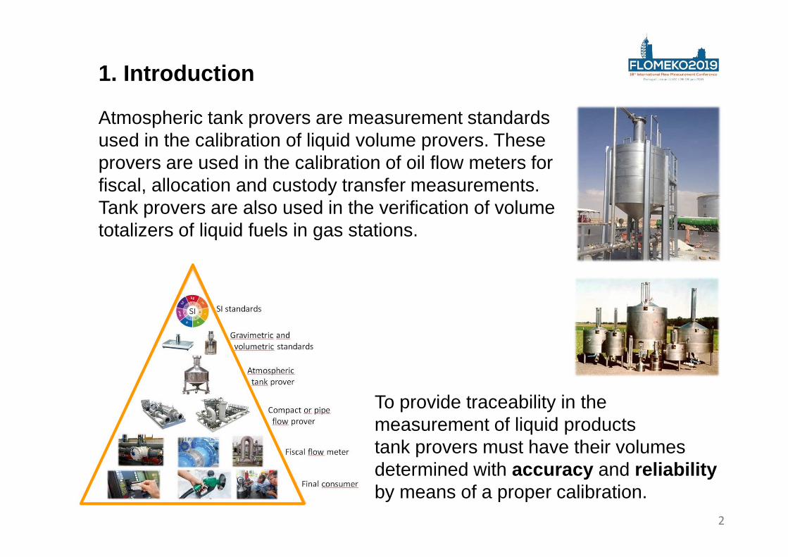
Atmospheric tank provers are measurement standards used in the calibration of liquid volume provers. These provers are used in the calibration of oil flow meters for fiscal, allocation and custody transfer measurements. Tank provers are also used in the verification of volume totalizers of liquid fuels in gas stations.
To provide traceability in the measurement of liquid products tank provers must have their volumes determined with accuracy and reliabilityby means of a proper calibration.
2
In turn, the satisfactory participation of calibration laboratories in proficiency testing activities and in other types of interlaboratorial comparisons consists in a mechanism established by the ISO/IEC 17025 standard for the laboratories to ensure the validity of their measurement results.
3
1. Introduction
2. Bilateral interlaboratory comparison
Under a common interest and agreement, the Institute for Technological Research (IPT) and the Weights and Measures Institute of the State of Sao Paulo (IPEM-SP) planned and carried out a bilateral interlaboratory comparison in the calibration service of atmospheric tank provers.
4
Institute for Technological Researchof the State of São Paulo (IPT)
Weights and Measures Institute of the State of Sao Paulo (IPEM-SP)
Both IPT and IPEM are public laboratories accredited by the Cgcre-General Coordination of Accreditation (the Brazilian ILAC member laboratory accreditation body).
Tank prover of 20 L Tank prover of 1 000 L
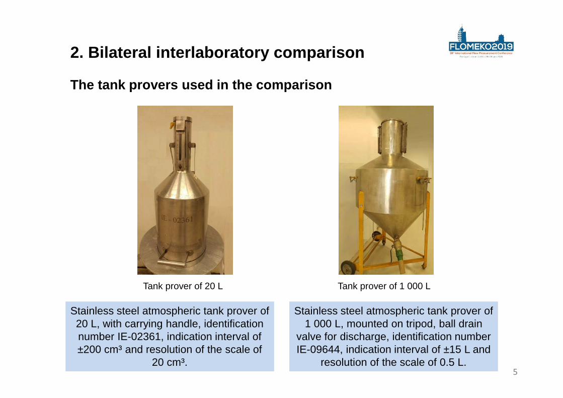
The tank provers used in the comparison
2. Bilateral interlaboratory comparison
Stainless steel atmospheric tank prover of 20 L, with carrying handle, identification number IE-02361, indication interval of ±200 cm³ and resolution of the scale of
20 cm³.
Stainless steel atmospheric tank prover of 1 000 L, mounted on tripod, ball drain
valve for discharge, identification number IE-09644, indication interval of ±15 L and
resolution of the scale of 0.5 L.5
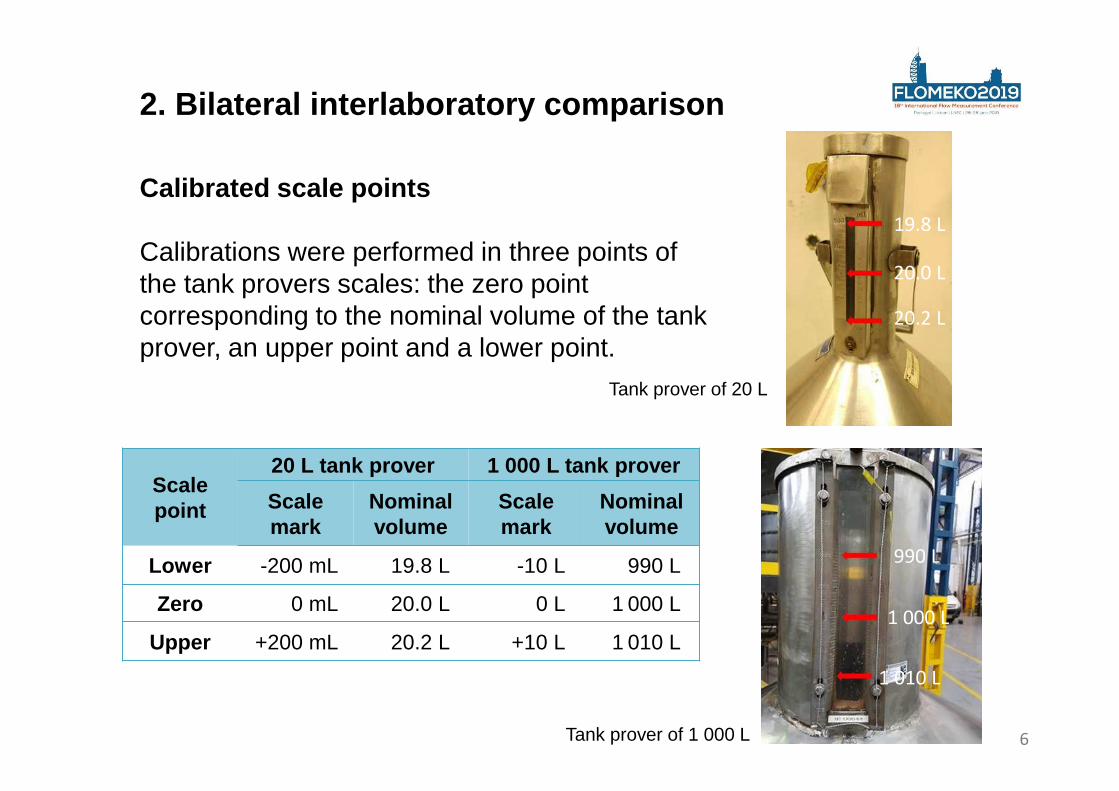
Calibrated scale points
Calibrations were performed in three points of the tank provers scales: the zero point corresponding to the nominal volume of the tank prover, an upper point and a lower point.
2. Bilateral interlaboratory comparison
Scale point
20 L tank prover 1 000 L tank prover
Scale mark
Nominal volume
Scale mark
Nominal volume
Lower -200 mL 19.8 L -10 L 990 L
Zero 0 mL 20.0 L 0 L 1 000 L
Upper +200 mL 20.2 L +10 L 1 010 L
Tank prover of 20 L
Tank prover of 1 000 L
19.8 L
20.0 L
20.2 L
990 L
1 000 L
1 010 L
6
3. Calibration methods
For the calibration of the tank provers each laboratory used its own method of calibration and calculation of results and uncertainties
IPEM-SP used the volumetric method and IPT used the gravimetric method of static weighing of the water contained in the tank prover.
Volumetric method
Calibration of an atmospheric tank prover by volumetric method consists on transfers of water from standard volume measures from which the transferred volume and its measurement uncertainty required for calibration is known.
7
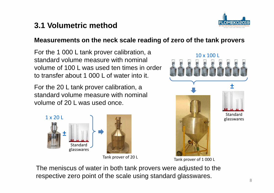
Measurements on the neck scale reading of zero of t he tank provers
3.1 Volumetric method
For the 1 000 L tank prover calibration, a standard volume measure with nominal volume of 100 L was used ten times in order to transfer about 1 000 L of water into it.
For the 20 L tank prover calibration, a standard volume measure with nominal volume of 20 L was used once.
1 x 20 L
Standard glasswares
±
Tank prover of 20 L
10 x 100 L
Standard glasswares
±
Tank prover of 1 000 L
The meniscus of water in both tank provers were adjusted to the respective zero point of the scale using standard glasswares.
8
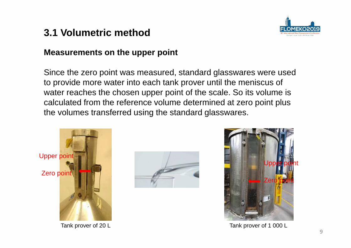
Measurements on the upper point
Since the zero point was measured, standard glasswares were used to provide more water into each tank prover until the meniscus of water reaches the chosen upper point of the scale. So its volume is calculated from the reference volume determined at zero point plus the volumes transferred using the standard glasswares.
Zero point
Upper point
Zero point
Upper point
Tank prover of 20 L Tank prover of 1 000 L
3.1 Volumetric method
9
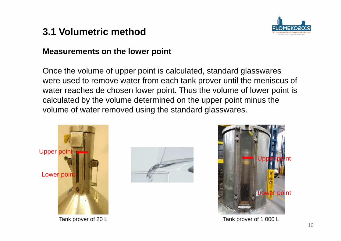
Measurements on the lower point
Once the volume of upper point is calculated, standard glasswareswere used to remove water from each tank prover until the meniscus of water reaches de chosen lower point. Thus the volume of lower point is calculated by the volume determined on the upper point minus the volume of water removed using the standard glasswares.
Lower point
Upper point
Lower point
Upper point
Tank prover of 20 L Tank prover of 1 000 L
3.1 Volumetric method
10
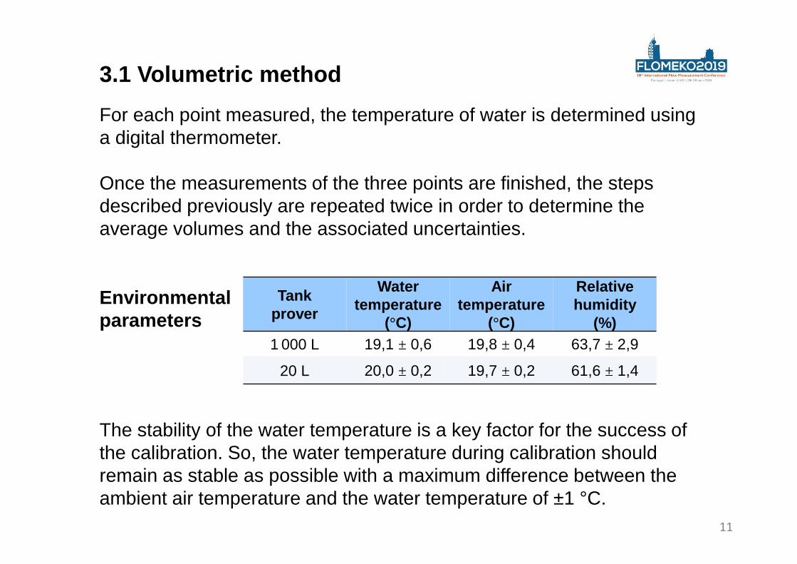
Environmental parameters
Tankprover
Water temperature
(°C)
Air temperature
(°C)
Relative humidity
(%)1 000 L 19,1 ± 0,6 19,8 ± 0,4 63,7 ± 2,9
20 L 20,0 ± 0,2 19,7 ± 0,2 61,6 ± 1,4
3.1 Volumetric method
For each point measured, the temperature of water is determined using a digital thermometer.
Once the measurements of the three points are finished, the steps described previously are repeated twice in order to determine the average volumes and the associated uncertainties.
The stability of the water temperature is a key factor for the success of the calibration. So, the water temperature during calibration should remain as stable as possible with a maximum difference between the ambient air temperature and the water temperature of ±1 °C.
11
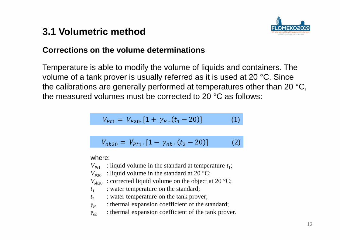
Corrections on the volume determinations
where:VPt1 : liquid volume in the standard at temperature t1;VP20 : liquid volume in the standard at 20 °C;Vob20 : corrected liquid volume on the object at 20 °C;t1 : water temperature on the standard;t2 : water temperature on the tank prover;γP : thermal expansion coefficient of the standard;γob : thermal expansion coefficient of the tank prover.
����� =��. [1 −���. �� − 20 ] (2)
�� =����. [1 +��. � − 20 ] (1)
3.1 Volumetric method
Temperature is able to modify the volume of liquids and containers. The volume of a tank prover is usually referred as it is used at 20 °C. Since the calibrations are generally performed at temperatures other than 20 °C, the measured volumes must be corrected to 20 °C as follows:
12

Main sources of measurement uncertainties
3.1 Volumetric method
Uncertainties were calculated according to the ISO GUM.
Standard deviation of volume measurements
Uncertainties associated to thestandard volumes measures
Uncertainties associated tothe glasswares volumes
Uncertainties associatedto the water temperatures Tank prover volume
13
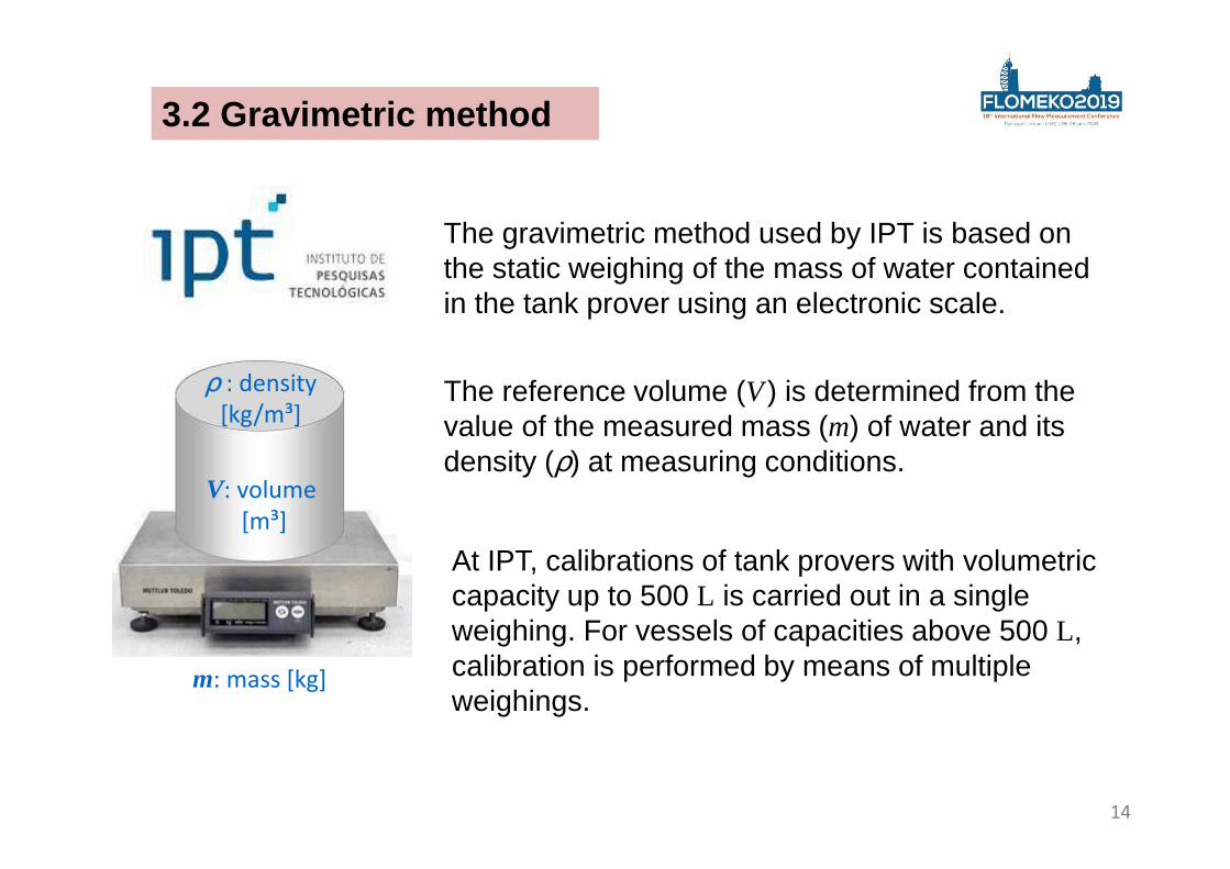
The gravimetric method used by IPT is based on the static weighing of the mass of water contained in the tank prover using an electronic scale.
At IPT, calibrations of tank provers with volumetric capacity up to 500 L is carried out in a single weighing. For vessels of capacities above 500 L, calibration is performed by means of multiple weighings.
3.2 Gravimetric method
m: mass [kg]
V: volume
[m³]
ρ : density
[kg/m³]
14
The reference volume (V ) is determined from the value of the measured mass (m) of water and its density (ρ) at measuring conditions.
3.2 Gravimetric method
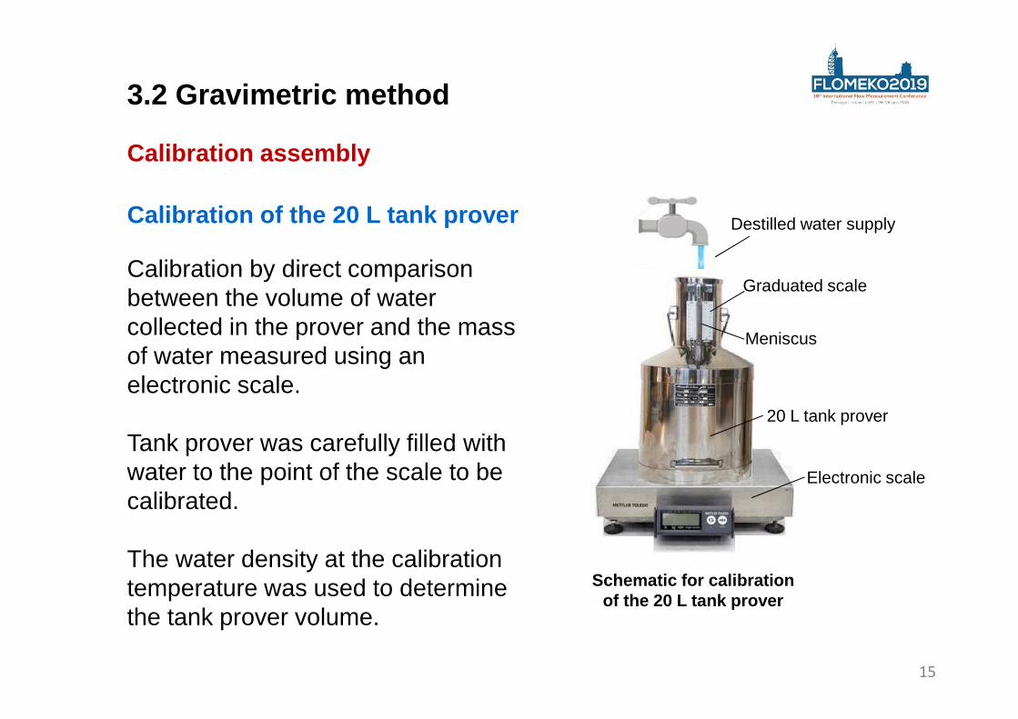
Calibration of the 20 L tank prover
Calibration by direct comparison between the volume of water collected in the prover and the mass of water measured using an electronic scale.
Tank prover was carefully filled with water to the point of the scale to be calibrated.
The water density at the calibration temperature was used to determine the tank prover volume.
Schematic for calibration of the 20 L tank prover
Graduated scale
Meniscus
Electronic scale
20 L tank prover
Destilled water supply
15
Calibration assembly
3.2 Gravimetric method
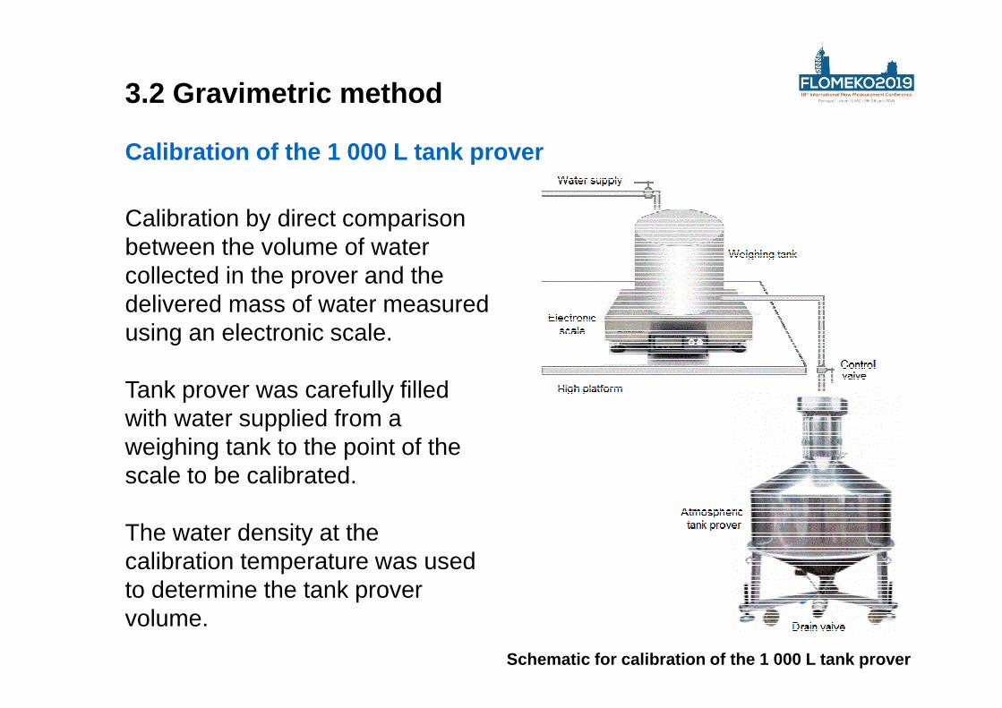
Calibration of the 1 000 L tank prover
Calibration by direct comparison between the volume of water collected in the prover and the delivered mass of water measured using an electronic scale.
Tank prover was carefully filled with water supplied from a weighing tank to the point of the scale to be calibrated.
The water density at the calibration temperature was used to determine the tank prover volume.
16Schematic for calibration of the 1 000 L tank prove r
3.2 Gravimetric method
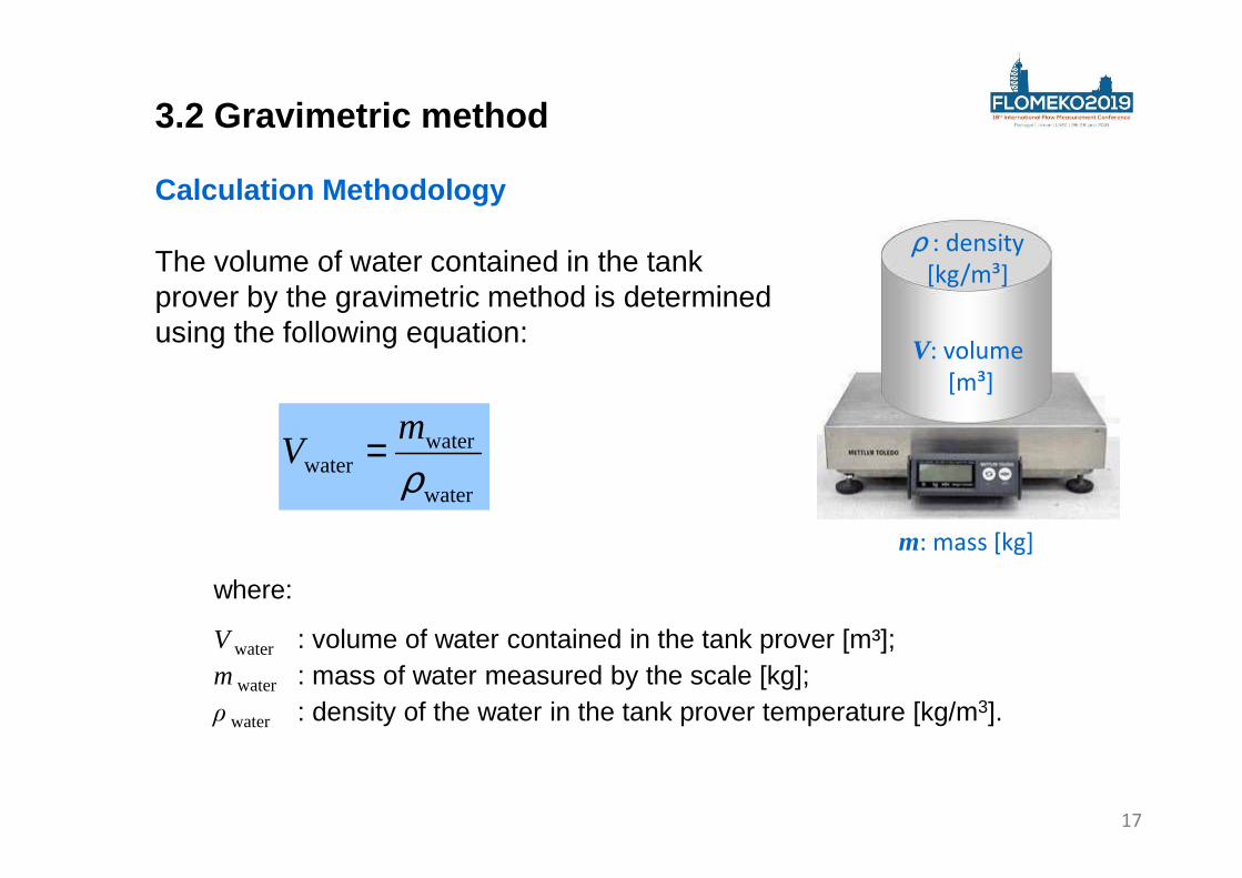
Calculation Methodology
water
waterwater ρ
mV =
where:
V water : volume of water contained in the tank prover [m³];m water : mass of water measured by the scale [kg];ρ water : density of the water in the tank prover temperature [kg/m3].
The volume of water contained in the tank prover by the gravimetric method is determined using the following equation:
17
m: mass [kg]
V: volume
[m³]
ρ : density
[kg/m³]
3.2 Gravimetric method
Calculation Methodology
where:
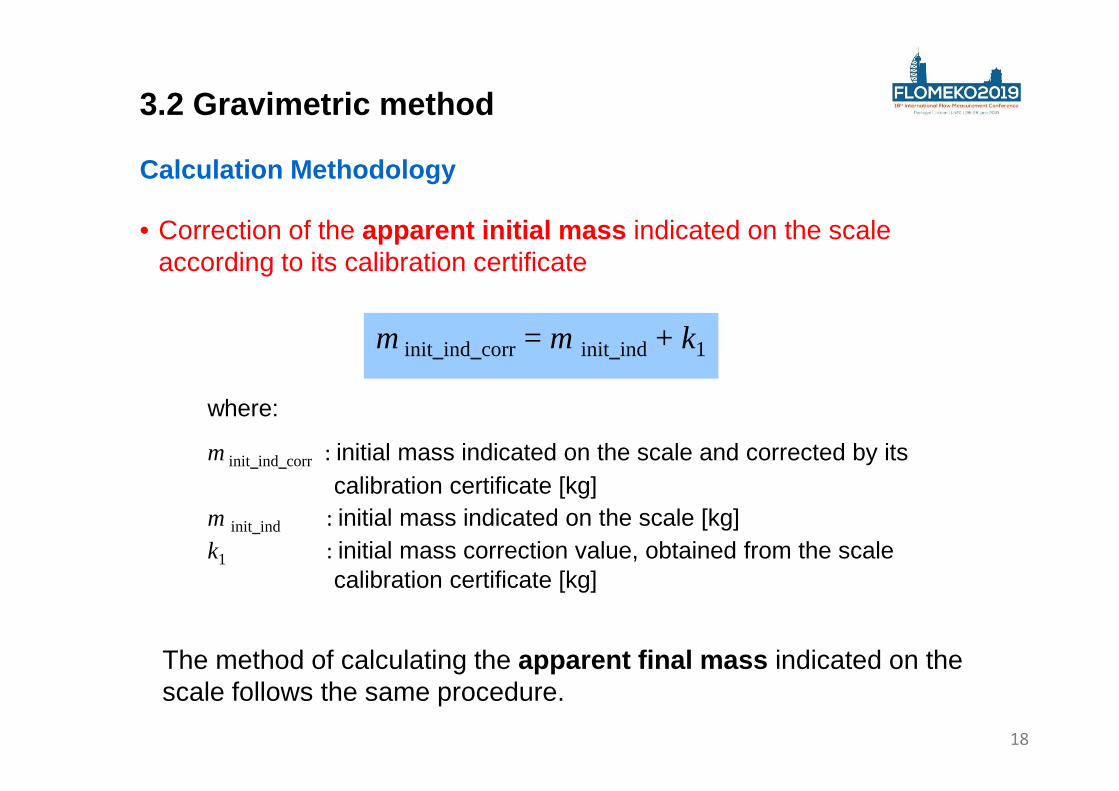
m init_ind_corr : initial mass indicated on the scale and corrected by itscalibration certificate [kg]
m init_ind : initial mass indicated on the scale [kg]k1 : initial mass correction value, obtained from the scale
calibration certificate [kg]
• Correction of the apparent initial mass indicated on the scale according to its calibration certificate
m init_ind_corr= m init_ind + k1
The method of calculating the apparent final mass indicated on the scale follows the same procedure.
18
3.2 Gravimetric method
where:
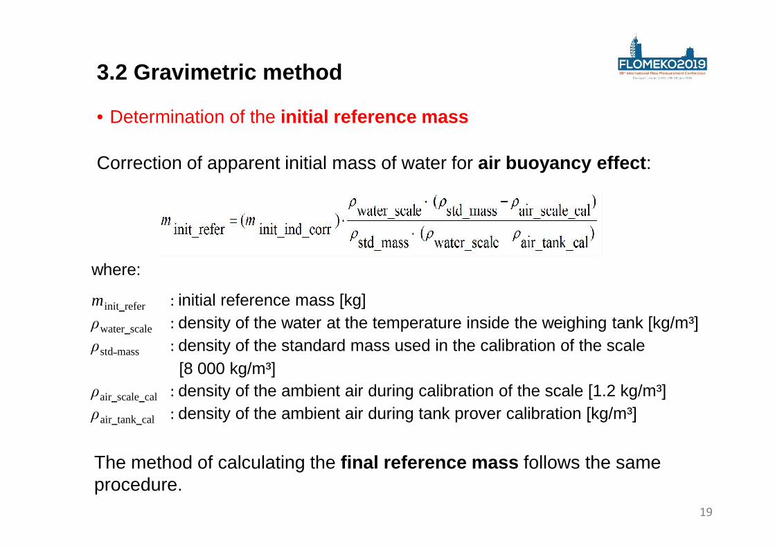
m init_refer : initial reference mass [kg]ρwater_scale : density of the water at the temperature inside the weighing tank [kg/m³]ρstd mass : density of the standard mass used in the calibration of the scale
[8 000 kg/m³]ρair_scale_cal : density of the ambient air during calibration of the scale [1.2 kg/m³]ρair_tank_cal : density of the ambient air during tank prover calibration [kg/m³]
• Determination of the initial reference mass
The method of calculating the final reference mass follows the same procedure.
Correction of apparent initial mass of water for air buoyancy effect :
19
3.2 Gravimetric method
where:
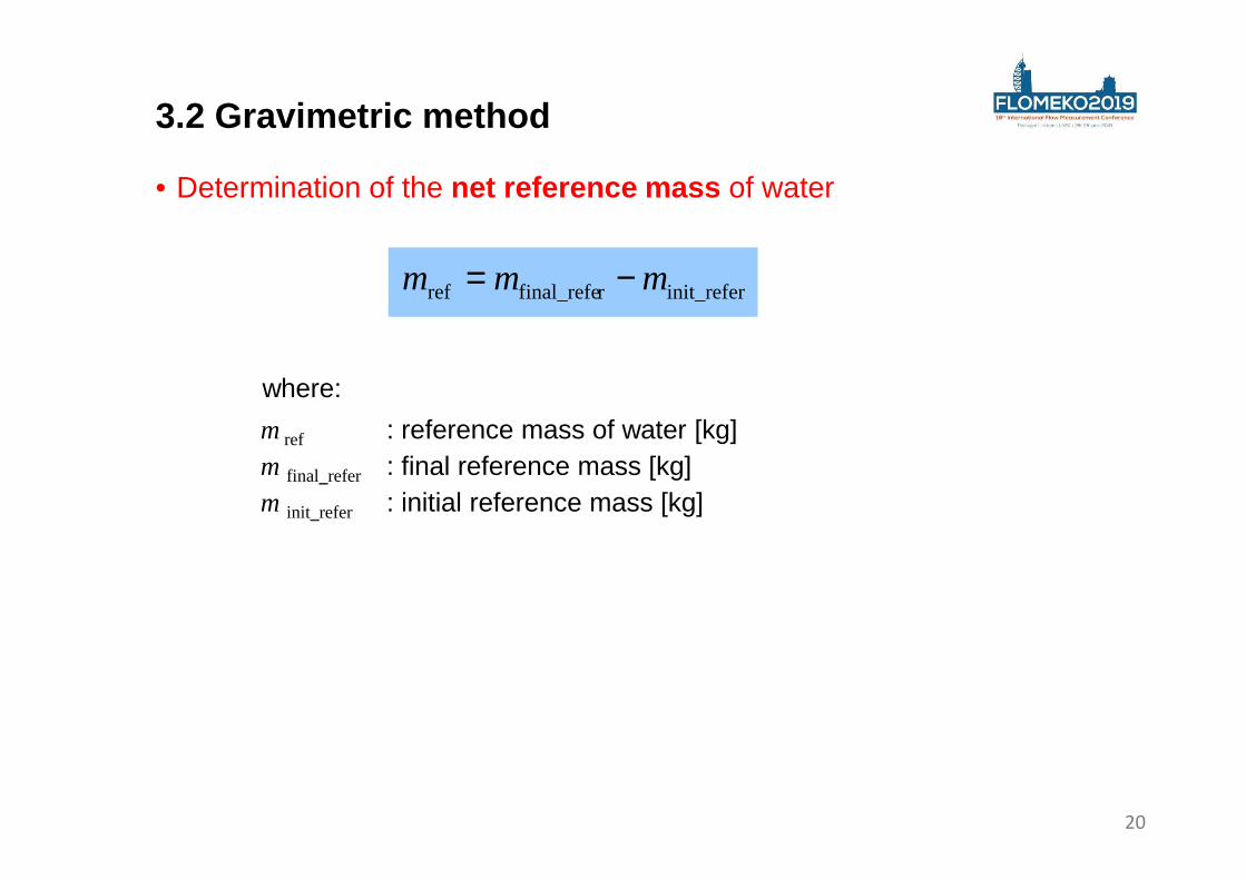
• Determination of the net reference mass of water
m ref : reference mass of water [kg]m final_refer : final reference mass [kg]m init_refer : initial reference mass [kg]
init_referrfinal_referef mmm −=
20
3.2 Gravimetric method
• Density of water used in tank prover calibration
where:
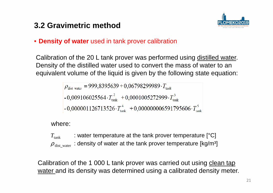
Ttank : water temperature at the tank prover temperature [°C]ρ dist_water : density of water at the tank prover temperature [kg/m³]
Calibration of the 20 L tank prover was performed using distilled water. Density of the distilled water used to convert the mass of water to an equivalent volume of the liquid is given by the following state equation:
Calibration of the 1 000 L tank prover was carried out using clean tap water and its density was determined using a calibrated density meter.
21
3.2 Gravimetric method
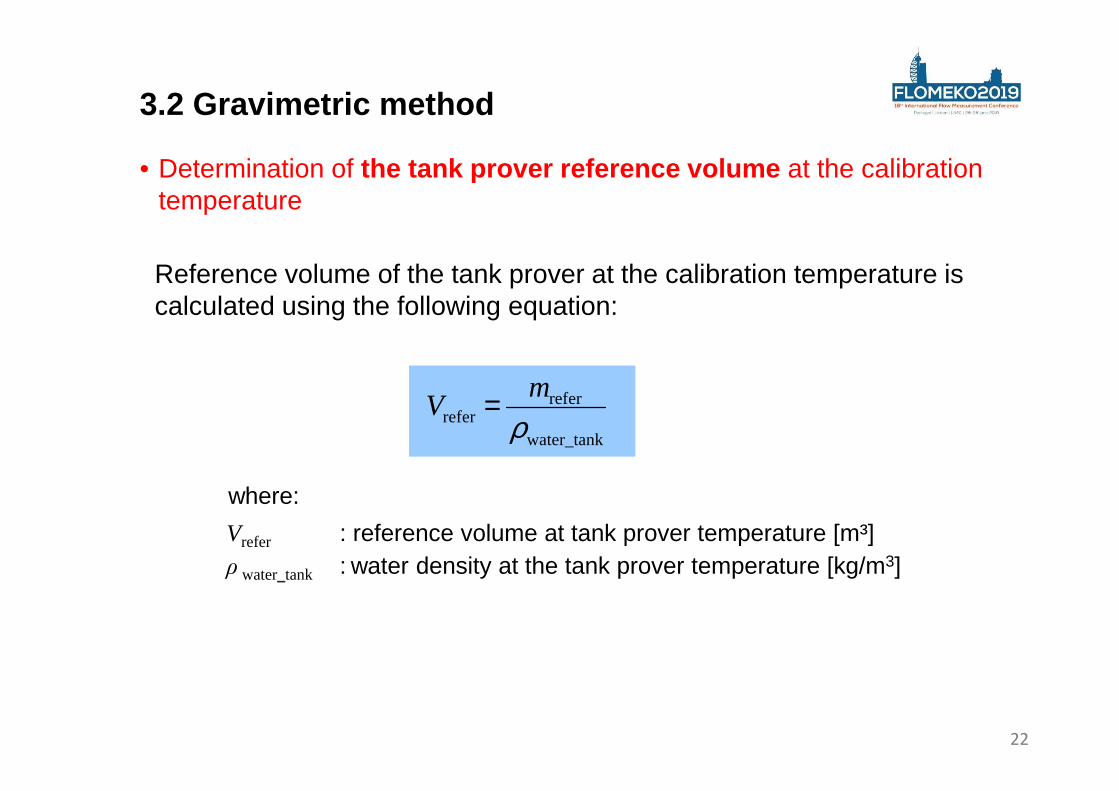
• Determination of the tank prover reference volume at the calibration temperature
where:
Vrefer : reference volume at tank prover temperature [m³]ρ water_tank : water density at the tank prover temperature [kg/m3]
Reference volume of the tank prover at the calibration temperature is calculated using the following equation:
water_tank
referrefer ρ
mV =
22
3.2 Gravimetric method
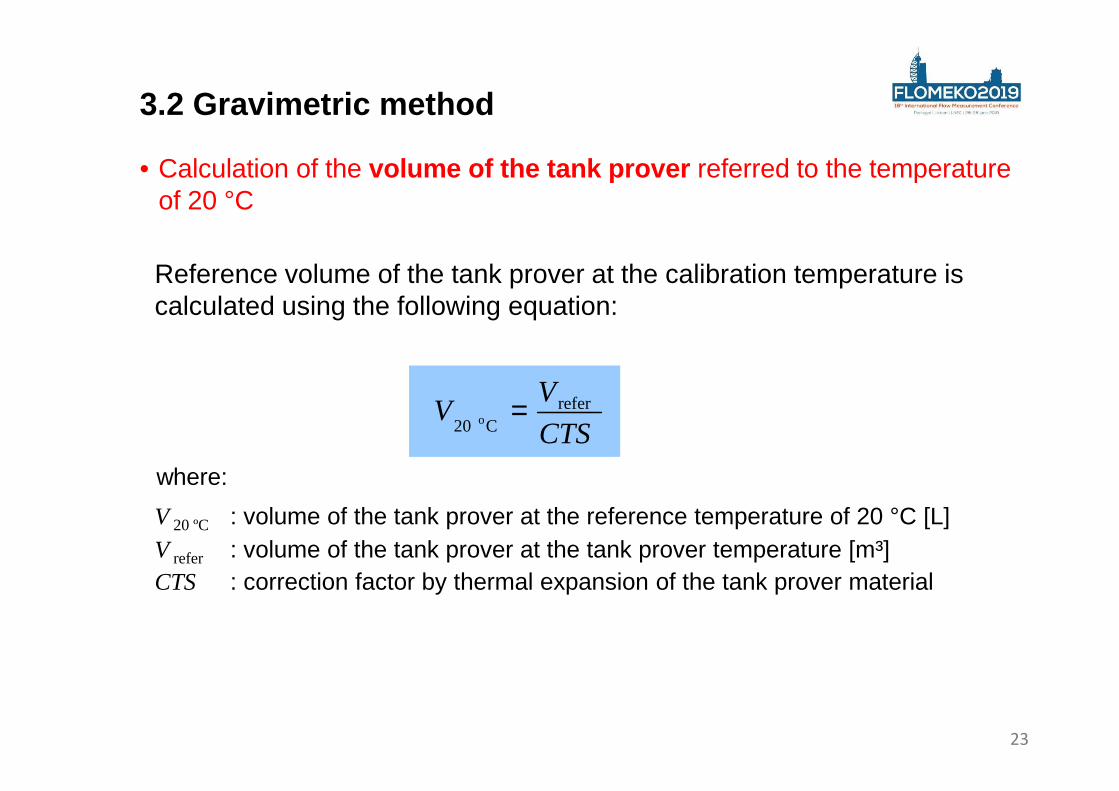
• Calculation of the volume of the tank prover referred to the temperature of 20 °C
where:
V 20 ºC : volume of the tank prover at the reference temperature of 20 °C [L]V refer : volume of the tank prover at the tank prover temperature [m³]CTS : correction factor by thermal expansion of the tank prover material
Reference volume of the tank prover at the calibration temperature is calculated using the following equation:
CTS
VV refer
C 20 o =
23
3.2 Gravimetric method
where:
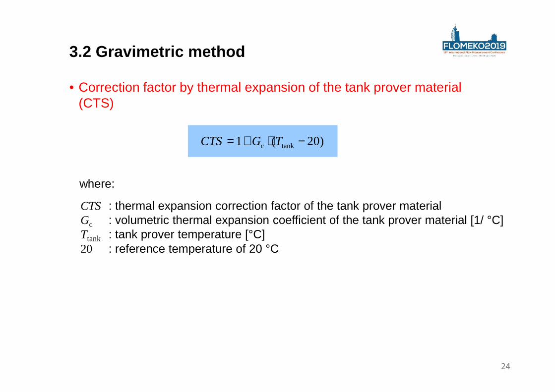
• Correction factor by thermal expansion of the tank prover material (CTS)
CTS : thermal expansion correction factor of the tank prover materialGc : volumetric thermal expansion coefficient of the tank prover material [1/ °C]Ttank : tank prover temperature [°C]20 : reference temperature of 20 °C
)20(1 tankc −⋅+= TGCTS
24
3.2 Gravimetric method
where:
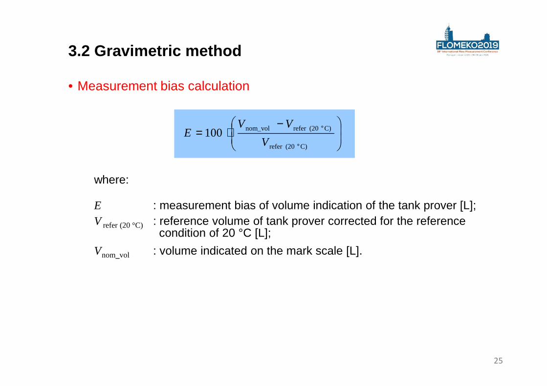
• Measurement bias calculation
E : measurement bias of volume indication of the tank prover [L];V refer (20 °C) : reference volume of tank prover corrected for the reference
condition of 20 °C [L];
Vnom_vol : volume indicated on the mark scale [L].
−⋅=
°
°
C) (20refer
C) (20refer nom_vol100V
VVE
25
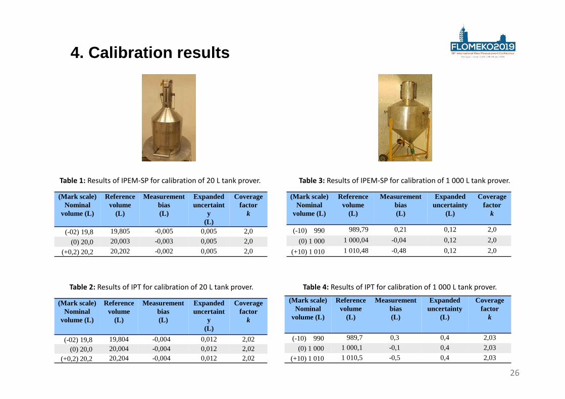
4. Calibration results
(Mark scale) Nominal
volume (L)
Reference volume
(L)
Measurement bias(L)
Expanded uncertaint
y(L)
Coverage factor
k
(-02) 19,8 19,805 -0,005 0,005 2,0
(0) 20,0 20,003 -0,003 0,005 2,0
(+0,2) 20,2 20,202 -0,002 0,005 2,0
Table 1: Results of IPEM-SP for calibration of 20 L tank prover.
(Mark scale) Nominal
volume (L)
Reference volume
(L)
Measurement bias(L)
Expanded uncertaint
y(L)
Coverage factor
k
(-02) 19,8 19,804 -0,004 0,012 2,02
(0) 20,0 20,004 -0,004 0,012 2,02
(+0,2) 20,2 20,204 -0,004 0,012 2,02
Table 2: Results of IPT for calibration of 20 L tank prover.
(Mark scale) Nominal
volume (L)
Reference volume
(L)
Measurement bias(L)
Expanded uncertainty
(L)
Coverage factor
k
(-10) 990 989,79 0,21 0,12 2,0
(0) 1 000 1 000,04 -0,04 0,12 2,0
(+10) 1 010 1 010,48 -0,48 0,12 2,0
Table 3: Results of IPEM-SP for calibration of 1 000 L tank prover.
(Mark scale) Nominal
volume (L)
Reference volume
(L)
Measurement bias(L)
Expanded uncertainty
(L)
Coverage factor
k
(-10) 990 989,7 0,3 0,4 2,03
(0) 1 000 1 000,1 -0,1 0,4 2,03
(+10) 1 010 1 010,5 -0,5 0,4 2,03
Table 4: Results of IPT for calibration of 1 000 L tank prover.
26
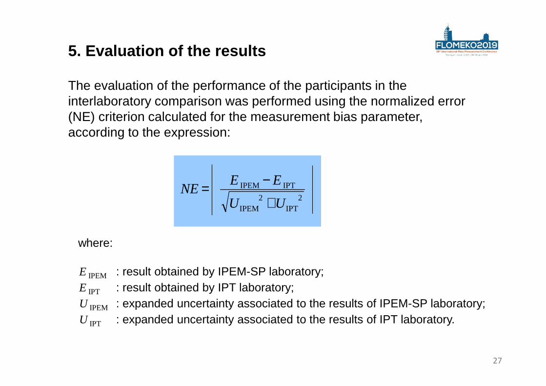
5. Evaluation of the results
The evaluation of the performance of the participants in the interlaboratory comparison was performed using the normalized error (NE) criterion calculated for the measurement bias parameter, according to the expression:
where:
E IPEM : result obtained by IPEM-SP laboratory;E IPT : result obtained by IPT laboratory;U IPEM : expanded uncertainty associated to the results of IPEM-SP laboratory;U IPT : expanded uncertainty associated to the results of IPT laboratory.
2
IPT2
IPEM
IPT IPEM
UU
EENE
+
−=
27
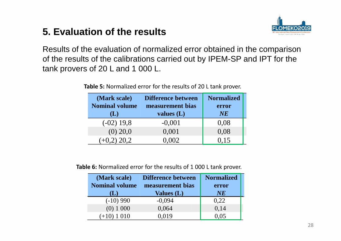
5. Evaluation of the results
Results of the evaluation of normalized error obtained in the comparison of the results of the calibrations carried out by IPEM-SP and IPT for the tank provers of 20 L and 1 000 L.
(Mark scale) Nominal volume
(L)
Difference between measurement bias
values (L)
NormalizederrorNE
(-02) 19,8 -0,001 0,08(0) 20,0 0,001 0,08
(+0,2) 20,2 0,002 0,15
Table 5: Normalized error for the results of 20 L tank prover.
Table 6: Normalized error for the results of 1 000 L tank prover.
(Mark scale) Nominal volume
(L)
Difference between measurement bias
Values (L)
NormalizederrorNE
(-10) 990 -0,094 0,22(0) 1 000 0,064 0,14
(+10) 1 010 0,019 0,0528
Results presented in Tables 1 to 6 show that the performance of the laboratories in the calibrations were quite satisfactory for both atmospheric tank provers, especially considering that different calibration methods were used for determination of the reference volumes.
The normalized errors obtained for both tank provers indicates a very satisfactory comparability between the two calibration methods.
6. Conclusion
29

Thank youfor your attention!
30