big-ip installation guideytan/i450-02/materials/bigip_install.pdf · installation guide i service...
TRANSCRIPT

BIG-IP® Installation Guide
version 4.0
MAN-0035-00
Service and Support Information
Product VersionThis manual applies to version 4.0 of the BIG-IP® Controller.
Obtaining Technical Support
Contacting F5 Networks
Web tech.f5.com
Phone (206) 272-6888
Fax (206) 272-6802
Email (support issues)
Email (suggestions) [email protected]
Web www.f5.com
Toll-free phone (888) 961-7242
Corporate phone (206) 272-5555
Fax (206) 272-5556
Email [email protected]
Mailing Address 401 Elliott Avenue WestSeattle, Washington 98119
Installation Guide i

Legal Notices
Copyright
F5 Networks, Inc. (F5) believes the information it furnishes to be accurate and reliable. However, F5 assumes no responsibility for the use of this information, nor any infringement of patents or other rights of third parties which may result from its use. No license is granted by implication or otherwise under any patent, copyright, or other intellectual property right of F5 except as specifically described herein. F5 reserves the right to change specifications at any time without notice.
Copyright 1997-2001, F5 Networks, Inc. All rights reserved.
Trademarks
F5, BIG-IP, 3-DNS, SEE-IT, and GLOBAL-SITE are registered trademarks of F5 Networks, Inc. EDGE-FX, iControl, and FireGuard are trademarks of F5 Networks, Inc. Other product and company names are registered trademarks or trademarks of their respective holders.
Export Regulation Notice
The BIG-IP® Controller may include cryptographic software. Under the Export Administration Act, the United States government may consider it a criminal offense to export this BIG-IP® Controller from the United States.
Export Warning
This is a Class A product. In a domestic environment this product may cause radio interference in which case the user may be required to take adequate measures.
FCC Compliance
This equipment generates, uses, and may emit radio frequency energy. The equipment has been type tested and found to comply with the limits for a Class A digital device pursuant to Part 15 of FCC rules, which are designed to provide reasonable protection against such radio frequency interference.
Operation of this equipment in a residential area may cause interference, in which case the user at his own expense will be required to take whatever measures may be required to correct the interference.
Any modifications to this device, unless expressly approved by the manufacturer, can void the user's authority to operate this equipment under part 15 of the FCC rules.
Canadian Regulatory Compliance
This class A digital apparatus complies with Canadian I CES-003.
Standards Compliance
The product conforms to ANSI/UL Std 1950 and Certified to CAN/CSA Std. C22.2 No. 950.
ii BIG-IP® Controller 4.0

Acknowledgments
This product includes software developed by the University of California, Berkeley and its contributors.
This product includes software developed by the Computer Systems Engineering Group at the Lawrence Berkeley Laboratory.
This product includes software developed by the NetBSD Foundation, Inc. and its contributors.
This product includes software developed by Christopher G. Demetriou for the NetBSD Project.
This product includes software developed by Adam Glass.
This product includes software developed by Christian E. Hopps.
This product includes software developed by Dean Huxley.
This product includes software developed by John Kohl.
This product includes software developed by Paul Kranenburg.
This product includes software developed by Terrence R. Lambert.
This product includes software developed by Philip A. Nelson.
This product includes software developed by Herb Peyerl.
This product includes software developed by Jochen Pohl for the NetBSD Project.
This product includes software developed by Chris Provenzano.
This product includes software developed by Theo de Raadt.
This product includes software developed by David Muir Sharnoff.
This product includes software developed by SigmaSoft, Th. Lockert.
This product includes software developed for the NetBSD Project by Jason R. Thorpe.
This product includes software developed by Jason R. Thorpe for And Communications, http://www.and.com.
This product includes software developed for the NetBSD Project by Frank Van der Linden.
This product includes software developed for the NetBSD Project by John M. Vinopal.
This product includes software developed by Christos Zoulas.
This product includes software developed by Charles Hannum.
This product includes software developed by Charles Hannum, by the University of Vermont and State Agricultural College and Garrett A. Wollman, by William F. Jolitz, and by the University of California, Berkeley, Lawrence Berkeley Laboratory, and its contributors.
This product includes software developed by the University of Vermont and State Agricultural College and Garrett A. Wollman.
In the following statement, "This software" refers to the Mitsumi CD-ROM driver: This software was developed by Holger Veit and Brian Moore for use with "386BSD" and similar operating systems. "Similar operating systems" includes mainly non-profit oriented systems for research and education, including but not restricted to "NetBSD," "FreeBSD," "Mach" (by CMU).
In the following statement, "This software" refers to the parallel port driver: This software is a component of "386BSD" developed by William F. Jolitz, TeleMuse.
Installation Guide iii

This product includes software developed by the Apache Group for use in the Apache HTTP server project (http://www.apache.org/).
This product includes software developed by Darren Reed. (© 1993-1998 by Darren Reed).
This product includes software licensed from Richard H. Porter under the GNU Library General Public License (© 1998, Red Hat Software), www.gnu.org/copyleft/lgpl.html.
This product includes the standard version of Perl software licensed under the Perl Artistic License (© 1997, 1998 Tom Christiansen and Nathan Torkington). All rights reserved. You may find the most current standard version of Perl at http://www.perl.com.
iv BIG-IP® Controller 4.0

Table of Contents
Table of Contents
IntroductionGetting started ....................................................................................................... Intro-1
Choosing a configuration tool ................................................................... Intro-1Using the Administrator Kit ............................................................................... Intro-2
Stylistic conventions .................................................................................... Intro-3Finding additional help and technical support resources .................... Intro-6
What’s new in version 4.0 ................................................................................... Intro-73-DNS on the BIG-IP Controller ............................................................. Intro-7OneConnect™ content switching with HTTP Keep-Alives .............. Intro-7Bridging and Layer 2 forwarding ............................................................... Intro-7HTTP Redirect pool property .................................................................. Intro-8Load balance any IP protocol .................................................................... Intro-8Link aggregation and fail-over .................................................................... Intro-8On-the-fly content converter .................................................................... Intro-8SNAT automap feature ............................................................................... Intro-9Health monitors ........................................................................................... Intro-9Performance monitors ................................................................................ Intro-9Default controller configuration ............................................................... Intro-9Web-based Configuration utility enhancements .................................Intro-10
Learning more about the BIG-IP Controller product family .....................Intro-10
1Setting Up the Hardware
Unpacking the hardware .............................................................................................1-1Hardware provided with the controller ........................................................1-1Peripheral hardware that you provide ...........................................................1-2
Familiarizing yourself with the controller ...............................................................1-3Using the 4U hardware configuration ............................................................1-3Using the 2U hardware configuration ............................................................1-6
Environmental requirements .....................................................................................1-7General guidelines ...............................................................................................1-8Guidelines for DC powered equipment ........................................................1-9
Installing and connecting the hardware ...................................................................1-9
2Creating the Initial Software Configuration
Gathering the information ..........................................................................................2-1First-Time Boot utility settings ..................................................................................2-1
Keyboard type ......................................................................................................2-1Product selection ................................................................................................2-2Root password .....................................................................................................2-2Host name .............................................................................................................2-3
Installation Guide vii

Table of Contents
Default route ........................................................................................................2-3Redundant system settings ................................................................................2-3Interface media settings .....................................................................................2-4VLANs and IP addresses ....................................................................................2-5Remote web server access ...............................................................................2-6Time zone .............................................................................................................2-7DNS forwarding proxy settings .......................................................................2-7Remote administrative access ..........................................................................2-8NTP support .........................................................................................................2-9NameSurfer ..........................................................................................................2-9First-Time Boot utility configuration list ........................................................2-9
Starting the First-Time Boot utility ........................................................................2-12Running the utility from the console or serial terminal ...........................2-12Running the utility remotely ...........................................................................2-13
3Additional Setup Options
Overview of additional setup options .....................................................................3-1Defining additional host names .................................................................................3-1Downloading the SSH client to your administrative workstation ....................3-3
Downloading the F-Secure SSH client from the web server ....................3-3Setting up the F-Secure SSH client on a Windows 95 or Windows NT workstation ................................................................................3-4Setting up the F-Secure SSH client on a UNIX workstation ....................3-4
Addressing general networking issues .....................................................................3-5Addressing routing issues ..................................................................................3-6Configuring DNS on the BIG-IP Controller ...............................................3-10Configuring email ...............................................................................................3-13
Using a serial terminal with the BIG-IP Controller ............................................3-14Configuring a serial terminal in addition to the console ..........................3-16Configuring a serial terminal as the console ...............................................3-16Forcing a serial terminal to be the console .................................................3-17
Configuring RADIUS authentication ......................................................................3-18Using RADIUS ports on the BIG-IP Controller .........................................3-19Configuring sshd version 2.x ..........................................................................3-20Configuring sshd version 1.x ..........................................................................3-21
Index
viii BIG-IP® Controller 4.0

Introduction
• Getting started
• Using the Administrator Kit
• What’s new in version 4.0
• Learning more about the BIG-IP Controller product family
Introduction
Getting startedBefore you start installing the controller, we recommend that you browse the BIG-IP Administrator Guide and find the load balancing solution that most closely addresses your needs. If the BIG-IP Controller is running the 3-DNS software module, you may also want to browse the 3-DNS Administrator Guide to find a wide area load balancing solution. Briefly review the basic configuration tasks and the few pieces of information, such as IP addresses and host names, that you should gather in preparation for completing the tasks.
Once you find your solution and gather the necessary network information, turn back to the Installation Guide for hardware installation instructions, and then return to the Administrator Guide to follow the steps for setting up your chosen solution.
Choosing a configuration tool
The BIG-IP Controller offers both web-based and command line configuration tools, so that users can work in the environment that they are most comfortable with.
The First-Time Boot utility
All users will use the First-Time Boot utility, a wizard that walks you through the initial system set up. You can run the First-Time Boot utility from the command line, or from a web browser. The First-Time Boot utility prompts you to enter basic system information including a root password and the IP addresses that will be assigned to the network interfaces. The BIG-IP Installation Guide provides a list of the specific pieces of information that the First-Time Boot utility prompts you to enter.
The Configuration utility
The Configuration utility is a web-based application that you use to configure and monitor the load balancing setup on the BIG-IP Controller. Once you complete the installation instructions described in this guide, you can use the Configuration utility to
Installation Guide Intro - 1

Introduction
perform the configuration steps necessary for your chosen load balancing solution. In the Configuration utility, you can also monitor current system performance, and download administrative tools such as the SNMP MIB or the SSH client. The Configuration utility requires Netscape Navigator version 4.7 or later, or Microsoft Internet Explorer version 5.0 or later.
The bigpipe and bigtop command line utilities
The bigpipe™ utility is the command line counter-part to the Configuration utility. Using bigpipe commands, you can configure virtual servers, open ports to network traffic, and configure a wide variety of features. To monitor the BIG-IP Controller, you can use certain bigpipe commands, or you can use the bigtop™ utility, which provides real-time system monitoring. You can use the command line utilities directly on the BIG-IP Controller console, or you can execute commands via a remote shell, such as the SSH client (encrypted communications only), or a Telnet client (for countries restricted by cryptography export laws). For detailed information about the command line syntax, see the BIG-IP Reference Guide, Chapter 2, bigpipe Command Reference, and the BIG-IP Administrator Guide, Chapter 18, Monitoring and Administration.
Using the Administrator KitThe BIG-IP® Administrator Kit provides all of the documentation you need to work with the BIG-IP Controller. The information is organized into the guides described below.
◆ BIG-IP Installation GuideThis guide walks you through the basic steps needed to get the hardware plugged in and the system connected to the network. Most users turn to this guide only the first time that they set up a controller. The BIG-IP Installation Guide also covers general network administration issues, such as setting up common network administration tools including Sendmail.
Intro - 2 BIG-IP® Controller 4.0
Introduction
◆ BIG-IP Administrator GuideThis guide provides examples of common load balancing solutions, as well as additional administrative information. Before you begin installing the controller hardware, we recommend that you browse this guide to find the load balancing solution that works best for you.
◆ BIG-IP Reference GuideThis guide provides basic descriptions of individual BIG-IP objects, such as pools, nodes, and virtual servers. It also provides syntax information for bigpipe commands, other command line utilities, configuration files, and system utilities.
◆ F-Secure SSH User GuideThis guide provides information about installing and working with the SSH client, a command line shell that supports remote encrypted communications. The SSH client and corresponding user guide is distributed only with BIG-IP Controllers that support encryption.
◆ 3-DNS Administrator and Reference GuidesIf your BIG-IP Controller includes the optional 3-DNS software module, your administrator kit also includes manuals for using 3-DNS Controller software. The 3-DNS Administrator Guide provides wide area load balancing solutions and general administrative information. The 3-DNS Reference Guide provides information about configuration file syntax and system utilities specific to the 3-DNS Controller.
Stylistic conventions
To help you easily identify and understand important information, our documentation uses the stylistic conventions described below.
Using the solution examples
All examples in this documentation use only non-routable IP addresses. When you set up the solutions we describe, you must use IP addresses suitable to your own network in place of our sample addresses.
Installation Guide Intro - 3
Introduction
Identifying new terms
To help you identify sections where a term is defined, the term itself is shown in bold italic text. For example, a virtual server is a specific combination of a virtual address and virtual port, associated with a content site that is managed by a BIG-IP Controller or other type of host server.
Identifying references to objects, names, and commands
We apply bold text to a variety of items to help you easily pick them out of a block of text. These items include web addresses, IP addresses, utility names, and portions of commands, such as variables and keywords. For example, with the bigpipe pool <pool_name> show command, you can specify a specific pool to show by specifying a pool name for the <pool_name> variable.
Identifying references to other documents
We use italic text to denote a reference to another document. In references where we provide the name of a book as well as a specific chapter or section in the book, we show the book name in bold, italic text, and the chapter/section name in italic text to help quickly differentiate the two. For example, you can find information about bigpipe commands in the BIG-IP Reference Guide, bigpipe Command Reference.
Identifying command syntax
We show complete commands in bold Courier text. Note that we do not include the corresponding screen prompt, unless the command is shown in a figure that depicts an entire command line screen. For example, the following command shows the configuration of the specified pool name:bigpipe pool <pool_name> show
or b pool <pool_name> show
Intro - 4 BIG-IP® Controller 4.0

Introduction
Table Intro.1 explains additional special conventions used in command line syntax.
Item in text Description
\ Indicates that the command continues on the following line, and that users should type the entire command without typing a line break.
< > Identifies a user-defined parameter. For example, if the command has <your name>, type in your name, but do not include the brackets.
| Separates parts of a command.
[ ] Indicates that syntax inside the brackets is optional.
... Indicates that you can type a series of items.
Table Intro.1 Command line syntax conventions
Installation Guide Intro - 5

Introduction
Finding additional help and technical support resources
You can find additional technical information about this product in the following locations:
◆ Release notesRelease notes for the current version of this product are available from the product web server home page, and are also available on the technical support site. The release notes contain the latest information for the current version, including a list of new features and enhancements, a list of fixes, and, in some cases, a list of known issues.
◆ Online helpYou can find help online in three different locations:
• The web server on the product has PDF versions of the guides included in the Administrator Kit.
• The web-based Configuration utility has online help for each screen. Simply click the Help button in the toolbar.
• Individual bigpipe commands have online help, including command syntax and examples, in standard UNIX man page format. Simply type the command followed by the word help, and the BIG-IP Controller displays the syntax and usage associated with the command.
◆ Third-party documentation for software add-onsThe web server on the product contains online documentation for all third-party software, such as GateD.
◆ Technical support via the World Wide WebThe F5 Networks Technical Support web site, http://tech.F5.com, provides the latest technical notes, answers to frequently asked questions, updates for administrator guides (in PDF format), and the Ask F5 natural language question and answer engine. To access this site, you need to obtain a customer ID and a password from the F5 Help Desk.
Intro - 6 BIG-IP® Controller 4.0

Introduction
What’s new in version 4.0The BIG-IP Controller offers the following major new features in version 4.0, in addition to many smaller enhancements.
3-DNS on the BIG-IP Controller
With this release of the BIG-IP Controller, you can order the full wide-area load balancing functionality of the 3-DNS Controller combined with the local-area load balancing functionality of the BIG-IP Controller. An advantage you gain with this configuration is that the combined configuration requires less rack space.
OneConnect™ content switching with HTTP Keep-Alives
OneConnect content switching allows you to turn on the Keep-Alive functionality on your Web servers.
You can now configure BIG-IP Controller rules to support HTTP 1.1 Keep-Alive functionality. This feature allows you to benefit from the Keep-Alive features on your Web servers.
Another benefit of this feature is client aggregation. You can aggregate client connections by configuring a SNAT for inbound requests. This reduces the number of connections from the BIG-IP Controller to back-end servers and from clients to the BIG-IP Controller.
Bridging and Layer 2 forwarding
The bridging and Layer 2 forwarding functionality in this release provides the ability to bridge packets between VLANs and between VLANs on the same IP network. The layer 2 forwarding feature provides the ability to install a BIG-IP Controller without changing the IP network configuration. For an example of how to use layer 2 forwarding, see VLAN group in the BIG-IP Reference Guide, Chapter 1, Configuring the BIG-IP Controller.
Installation Guide Intro - 7
Introduction
HTTP Redirect pool property
The HTTP redirect feature adds the ability to redirect clients to another site or server or to a 3-DNS Controller when the members of a pool they were destined for are not available. For more information, see HTTP Redirect (specifying a fallback host) in the BIG-IP Reference Guide, Chapter 1, Configuring the BIG-IP Controller.
Load balance any IP protocol
The load balance any IP protocol feature provides the ability to load balance IP protocols other than TCP or UDP. This means that you can load balance VPN client connections across a number of VPNs, eliminating the possibility of a single point of failure. For more information, see the BIG-IP Administrator Guide, Chapter 7, Using IPSEC with VPN Gateways.
Link aggregation and fail-over
The link aggregation feature provides the ability to combine multiple Ethernet links into a single trunk. This allows you to increase available bandwidth incrementally and improve link reliability. For more information, see Trunks in the BIG-IP Reference Guide, Chapter 1, Configuring the BIG-IP Controller.
On-the-fly content converter
The on-the-fly content converter provides a simplified method of converting URLs in HTML files passing through the BIG-IP Controller to ARLs that point to the Akamai Freeflow NetworkTM. For more information, see the BIG-IP Administrator Guide, Chapter 13, Configuring a Content Converter.
Intro - 8 BIG-IP® Controller 4.0
Introduction
SNAT automap feature
The SNAT automap feature provides the ability to automatically map a SNAT to a BIG-IP Controller VLAN or self IP address. This simplifies the ability to load balance multiple internet ISPs. For more information, see SNATs in the BIG-IP Reference Guide, Chapter 1, Configuring the BIG-IP Controller.
Health monitors
This release contains predefined templates that you can use to define many different types of monitors (EAVs and ECVs) that check the health and availability of devices in the network. You can associate a monitor with a single node or many nodes. For more information, see the Health monitors in the BIG-IP Reference Guide, Chapter 1, Configuring the BIG-IP Controller.
Performance monitors
A performance monitor gathers statistics that are the basis for load balancing decisions made with the Dynamic Ratio load balancing method. You can implement Dynamic Ratio load balancing on RealNetworks RealServer platforms, Windows platforms equipped with Windows Management Instrumentation (WMI), and on platforms that support simple network management protocol (SNMP). For more information, see the Configuring servers and the BIG-IP Controller for Dynamic Ratio load balancing under Pools in the BIG-IP Reference Guide, Chapter 1, Configuring the BIG-IP Controller.
Default controller configuration
The BIG-IP Controller includes a default configuration that allows you to connect to a controller remotely and configure it by command line or from a web-based user interface. The default configuration provides a default IP address (RFC 1918) on the default internal VLAN or on the Admin VLAN if the controller has
Installation Guide Intro - 9
Introduction
three interfaces. You can connect to the default IP address and log on to the controller with the default user name and password. This provides the ability to run the First-Time Boot utility from a remote SSH client or from a web browser. For more information, see the BIG-IP Installation Guide, Chapter 2, Creating the Initial Software Configuration.
Web-based Configuration utility enhancements
This release includes a number of improvements to the web-based Configuration utility. There are new wizards for tasks such as adding virtual servers, rules, monitors, and initial setup. A new tab-style navigation system simplifies navigation in the utility. In addition to the wizards for completing simple tasks, this release includes several configuration wizards that simplify creating a configuration for the BIG-IP Controller. These wizards include the Basic Site Configuration wizard, the Secure Site Configuration wizard, and the Active-active wizard.
Learning more about the BIG-IP Controller product family
The BIG-IP Controller platform offers many different software systems. These systems can be stand-alone, or can run in redundant pairs, with the exception of the BIG-IP e-Commerce Controller, which is only available as a stand-alone system. You can easily upgrade from any special-purpose BIG-IP Controller to the BIG-IP HA Controller, which supports all BIG-IP Controller features.
◆ The BIG-IP HA Controller with optional 3-DNS software moduleThe BIG-IP HA Controller provides the full suite of local area load balancing functionality. The BIG-IP HA Controller also has an optional 3-DNS software module which supports wide-area load balancing.
Intro - 10 BIG-IP® Controller 4.0
Introduction
◆ The combined product BIG-IP ControllerThe combined product BIG-IP Controller provides the ability to choose from three different BIG-IP Controller feature sets. When you run the First-Time Boot utility, you specify the controller type:
• The BIG-IP LB Controller The BIG-IP LB Controller provides basic load balancing features.
• The BIG-IP FireGuard ControllerThe BIG-IP FireGuard Controller provides load balancing features that maximize the efficiency and performance of a group of firewalls.
• The BIG-IP Cache ControllerThe BIG-IP Cache Controller uses content-aware traffic direction to maximize the efficiency and performance of an group of cache servers.
◆ The BIG-IP e-Commerce ControllerThe BIG-IP e-Commerce Controller uses SSL acceleration technology to increase the speed and reliability of the secure connections that drive e-commerce sites.
Installation Guide Intro - 11

1
Setting Up the Hardware
• Unpacking the hardware
• Familiarizing yourself with the controller
• Environmental requirements
• Installing and connecting the hardware

Setting Up the Hardware
Unpacking the hardwareThere are four basic tasks you must complete to get the controller installed and set up.
• Review the hardware requirements
• Familiarize yourself with the controller hardware
• Review the environmental requirements
• Connect the controller to the network and optionally connect the peripheral hardware.
The controller comes with the hardware that you need for installation and maintenance. However, you must also provide standard peripheral hardware, such as a keyboard or serial terminal, if you want to administer the controller directly.
Hardware provided with the controller
When you unpack the controller, you should make sure that the following components are included:
• One power cable
• One PC/AT-to-PS/2 keyboard adapter
• Four rack-mounting screws
• Two keys for the front panel lock
• One extra fan filter
• One BIG-IP Administrator Kit
If you purchased a hardware-based redundant system, you also received one fail-over cable to connect the two controller units together (network-based redundant systems do not require a fail-over cable).
Installation Guide 1 - 1

Chapter 1
Peripheral hardware that you provide
For each controller in the system, you need to provide the following peripheral hardware:
◆ If you plan to use direct administrative access to the controller, you need standard input/output hardware for direct administrative access to the controller. Either of the following options is acceptable:
• A VGA monitor and PC/AT-compatible keyboard
• Optionally, a serial terminal and a null modem cable (see Using a serial terminal with the BIG-IP Controller, on page 3-14, for serial terminal configuration information)
◆ If you want to use the default controller configuration, you must have an administrative workstation on the same IP network as the BIG-IP Controller.
◆ You also need network hubs, switches, or concentrators to connect to the controller network interfaces. The devices you select must be compatible with the network interface cards installed in the controller. The devices can support 10/100 Ethernet, Gigabit Ethernet, or FDDI/CDDI (including multiple FDDI and full duplex).
• Ethernet requires either a 10 Mbps or 100 Mbps hub or switch
• FDDI/CDDI requires no additional hardware, but a concentrator or a switch is optional
• Gigabit Ethernet requires a compatible Gigabit Ethernet switch
If you plan on doing remote administration from your own PC workstation as most users do, we recommend that you have your workstation already in place. Keep in mind that the First-Time Boot utility prompts you to enter your workstation’s IP address when you set up remote administrative access.
1 - 2 BIG-IP® Controller 4.0

Setting Up the Hardware
Familiarizing yourself with the controllerThe controller is offered in 4U and 2U hardware configurations. Before you begin to install the controller, you may want to quickly review the following figures that illustrate the controls and ports on both the front and the back of a 4U controller and a 2U controller.
Using the 4U hardware configuration
This section describes the front and back layout of a 4U controller. If you have a special hardware configuration, such as those that include more than two interface cards, the ports on the back of your unit will differ slightly from those shown in Figure 1.2, on page 1-5.
Note
The interfaces on every controller are individually labeled, so it should be clear what each port is, no matter which hardware configuration you have purchased. For detailed information about interface naming, see the BIG-IP Reference Guide, Interface naming convention.
Installation Guide 1 - 3
Chapter 1
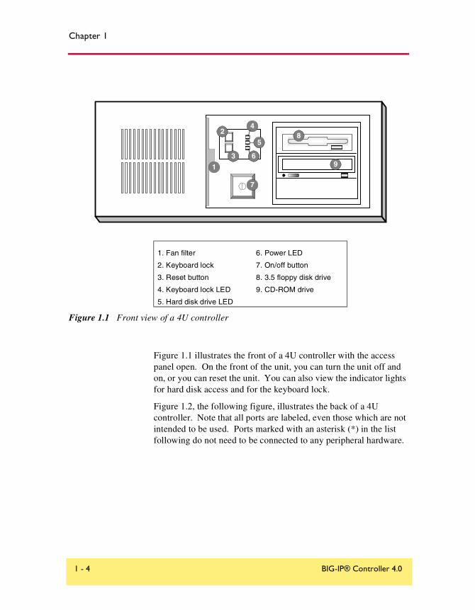
Figure 1.1 illustrates the front of a 4U controller with the access panel open. On the front of the unit, you can turn the unit off and on, or you can reset the unit. You can also view the indicator lights for hard disk access and for the keyboard lock.
Figure 1.2, the following figure, illustrates the back of a 4U controller. Note that all ports are labeled, even those which are not intended to be used. Ports marked with an asterisk (*) in the list following do not need to be connected to any peripheral hardware.
1. Fan filter
2. Keyboard lock
3. Reset button
4. Keyboard lock LED
5. Hard disk drive LED
6. Power LED
7. On/off button
8. 3.5 floppy disk drive
9. CD-ROM drive
Figure 1.1 Front view of a 4U controller
24
3
5
6
7
8
1 9
1 - 4 BIG-IP® Controller 4.0

Setting Up the Hardware
*Not to be connected to any peripheral hardware.
Figure 1.2 Back view of a 4U controller
1. Fan
2. Power in
3. Voltage selector
4. Mouse port*
5. Keyboard port
6. Universal serial bus ports*
7. Serial terminal port
8. Printer port*
9. Fail-over port
10. Video (VGA) port
11. Interface (RJ-45)
12. Interface (RJ-45)
13. Interface indicator LEDs
14. Watchdog card*
1
97
10
52 3
46
8
11
13
12
14
Installation Guide 1 - 5
Chapter 1
Using the 2U hardware configuration
This section describes the front and back layout of a 2U controller. If you have a special hardware configuration, such as those that include more than two interface cards, the ports on the back of your unit will differ slightly from those shown in Figure 1.4, on page 1-7.
Note
The interfaces on every controller are individually labeled, so it should be clear what each port is, no matter which hardware configuration you have purchased. For detailed information about interface naming, see the BIG-IP Reference Guide, Interface naming convention.
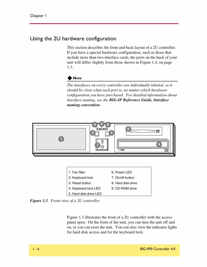
Figure 1.3 illustrates the front of a 2U controller with the access panel open. On the front of the unit, you can turn the unit off and on, or you can reset the unit. You can also view the indicator lights for hard disk access and for the keyboard lock.
1. Fan filter
2. Keyboard lock
3. Reset button
4. Keyboard lock LED
5. Hard disk drive LED
6. Power LED
7. On/off button
8. Hard disk drive
9. CD-ROM drive
Figure 1.3 Front view of a 2U controller
3
4
2
5 6
7 9
8
1
1 - 6 BIG-IP® Controller 4.0
Setting Up the Hardware
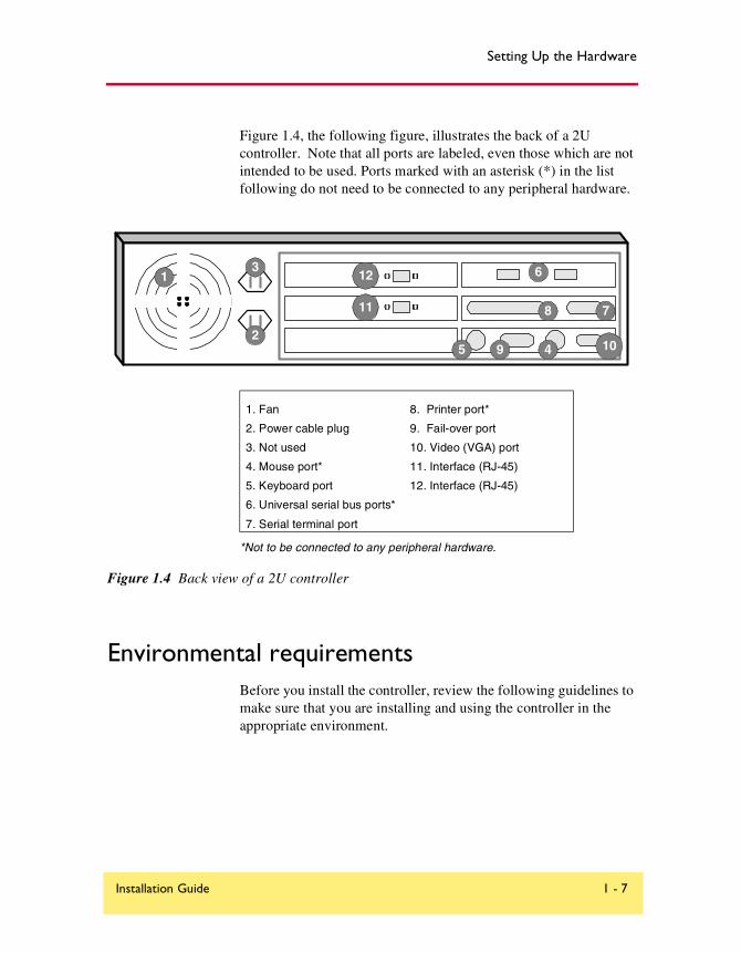
Figure 1.4, the following figure, illustrates the back of a 2U controller. Note that all ports are labeled, even those which are not intended to be used. Ports marked with an asterisk (*) in the list following do not need to be connected to any peripheral hardware.
*Not to be connected to any peripheral hardware.
Figure 1.4 Back view of a 2U controller
Environmental requirementsBefore you install the controller, review the following guidelines to make sure that you are installing and using the controller in the appropriate environment.
1. Fan
2. Power cable plug
3. Not used
4. Mouse port*
5. Keyboard port
6. Universal serial bus ports*
7. Serial terminal port
8. Printer port*
9. Fail-over port
10. Video (VGA) port
11. Interface (RJ-45)
12. Interface (RJ-45)
1
2
3
45
6
78
9 10
11
12
Installation Guide 1 - 7

Chapter 1
General guidelines
A controller is an industrial network appliance, designed to be mounted in a standard 19-inch rack. To ensure safe installation and operation of the unit:
• Install the rack according to the manufacturer’s instructions, and check the rack for stability before placing equipment in it.
• Build and position the rack so that once you install the controller, the power supply and the vents on both the front and back of the unit remain unobstructed. The controller must have adequate ventilation around the unit at all times.
• Do not allow the air temperature in the room to exceed 40° C.
• Do not plug the unit into a branch circuit shared by more electronic equipment than the circuit is designed to manage safely at one time.
• Verify that the voltage selector is set appropriately before connecting the power cable to the unit.
The unit must be connected to Earth ground, and itshould have a reliable ground path maintained at alltimes.
!
The controller contains a lithium battery. There is dangerof an explosion if you replace the lithium batteryincorrectly. We recommend that you replace the batteryonly with the same type of battery originally installed inthe unit, or with an equivalent type recommended by thebattery manufacturer. Be sure to discard all usedbatteries according to the manufacturer’s instructions.
1 - 8 BIG-IP® Controller 4.0
Setting Up the Hardware
Guidelines for DC powered equipmentA DC powered installation must meet the following requirements:
• Install the unit using a 20 Amp external branch circuit protection device.
• For permanently connected equipment, incorporate a readily accessible disconnect in the fixed wiring.
• Use only copper conductors.
Installing and connecting the hardwareThere are six basic steps to installing the hardware. You simply need to install the controller in the rack, connect the peripheral hardware and the external and internal interfaces, and then connect the fail-over and power cables. If you have a unit with three or more network interface cards (NICs), be sure to review step 3 in the following procedure.
WARNING
Do not turn on a controller until all peripheral hardware is connected to the unit.
This equipment is not intended for operatorserviceability. To prevent injury and to preserve themanufacturer’s warranty, allow only qualified servicepersonnel to service the equipment.
Install DC powered equipment only in restricted accessareas, such as dedicated equipment rooms, equipmentclosets, or similar locations.
Installation Guide 1 - 9

Chapter 1
To install the hardware
1. Insert the controller in the rack and secure it using the four rack-mounting screws that are provided.
2. Connect the hardware that you have chosen to use for input/output:
• If you are using a VGA monitor and keyboard, connect the monitor connector cable to the video port (number 10 in Figure 1.2 for 4U, or in Figure 2.4 for 2U), and connect the keyboard connector cable to the keyboard port (number 5 in Figure 1.2 for 4U, or in Figure 2.4 for 2U). Note that a PC/AT-to-PS/2 keyboard adapter is included with each controller (see the component list on page 1-1).
• Optionally, if you are using a serial terminal as the console, connect the serial cable to the terminal serial port (number 7 in Figure 1.2 for 4U, or in Figure 2.4 for 2U). Also, you should not connect a keyboard to the controller. If there is no keyboard connected to the controller when it is started or rebooted, the controller defaults to using the serial port as the console.
3. Connect the external interface (number 12 in Figure 1.2 for 4U, or in Figure 2.4 for 2U) to the network from which the controller receives connection requests.
If you have purchased a unit with three or more network interface cards (NICs), be sure to note or write down how you connect the cables to the internal and external interfaces. When you run the First-Time Boot utility, it automatically detects the number of interfaces that are installed and prompts you to configure more external interfaces, if you want. It is important to select the correct external interface based on the way you have connected the cables to the back of the unit.
4. Connect the internal interface (number 11 in Figure 1.2 for 4U, or in Figure 2.4 for 2U) to the network that houses the array of servers, routers, or firewalls that the controller load balances.
1 - 10 BIG-IP® Controller 4.0

Setting Up the Hardware
5. If you have a hardware-based redundant system, connect the fail-over cable to the terminal serial port on each unit (number 7 in Figure 1.2 for 4U, or number 7 in Figure 2.4 for 2U).
6. Connect the power cable to the controller (number 2 in Figure 1.2 for 4U, or Figure 2.4 for 2U), and then connect it to the power source.
WARNING
Before connecting the power cable to a power supply, customers outside the United States should make sure that the voltage selector is set appropriately. This check is necessary only if the controller has an external voltage selector.
Installation Guide 1 - 11

2
Creating the Initial Software Configuration
• Gathering the information
• First-Time Boot utility settings
• Starting the First-Time Boot utility
Creating the Initial Software Configuration
Gathering the informationOnce you install and connect the hardware, the next step in the installation process is to turn the system on and run the First-Time Boot utility. The First-Time Boot utility defines the initial configuration settings required to install the BIG-IP Controller into the network. You can run the First-Time Boot utility remotely from a web browser, or from an SSH or Telnet client, or you can run it directly from the console.
Before you connect to the controller, we recommend that you gather the list of information outlined in the following section. Note that the screens you see are tailored to the specific hardware and software configuration that you have. For example, if you have a stand-alone system, the First-Time Boot utility skips the redundant system screens.
Once you have gathered the information and are ready to run the utility, refer to Starting the First-Time Boot utility, on page 2-12.
First-Time Boot utility settingsThe following sections provide detailed information about the settings that you define in the First-Time Boot utility.
Tip
A list is provided at the end of this section where you can fill in this information. See First-Time Boot utility configuration list, on page 2-9
Keyboard type
Select the type of keyboard you want use with the BIG-IP Controller. The following options are available:
• Belgian
• Bulgarian MIK
Installation Guide 2 - 1
Chapter 2
• French
• German
• Japanese - 106 key
• Norwegian
• Spanish
• Swedish
• US + Cyrillic
• US - Standard 101 key
• United Kingdom
Product selection
If you are configuring a BIG-IP Cache Controller, BIG-IP Fire Guard, or BIG-IP Load Balancer, you must now select one of these three as your product. When you have made your selection, the features supported by that product will be enabled.
You may change your product selection at a later time using the config combo command.
WARNING
Once you have configured your system based on one of the three product selections (BIG-IP Cache Controller, BIG-IP Fire Guard, or BIG-IP Load Balancer), changing the product selection will most likely invalidate that configuration. Therefore you will need to change and update your configuration after you have rebooted the system under the new product selection.
Root passwordA root password allows you command line administrative access to the BIG-IP Controller system. The password must contain a minimum of 6 characters, but no more than 32 characters. Passwords are case-sensitive, and we recommend that your password contain a combination of upper- and lower-case
2 - 2 BIG-IP® Controller 4.0

Creating the Initial Software Configuration
characters, as well as numbers and punctuation characters. Once you enter a password, the First-Time Boot utility prompts you to confirm your root password by typing it again. If the two passwords match, your password is immediately saved. If the two passwords do not match, the First-Time Boot utility provides an error message and prompts you to re-enter your password.
WARNING
The root password and keyboard selection are the only settings that are saved immediately, rather than confirmed and committed at the end of the First-Time Boot utility process. You cannot change the root password until the First-Time Boot utility completes and you reboot the BIG-IP Controller (see the BIG-IP Administrator Guide, Monitoring and Administration). Note that you can change other system settings when the First-Time Boot utility prompts you to confirm your configuration settings.
Host name
The host name identifies the BIG-IP Controller itself. Host names must be fully qualified domain names (FQDNs). The host portion of the name must start with a letter, and must be at least two characters.
Default route
If a BIG-IP Controller does not have a predefined route for network traffic, the controller automatically sends traffic to the IP address that you define as the default route. Typically, a default route is set to a router’s IP address.
Redundant system settings
There are two types of settings you need to define for redundant systems: unit IDs, and fail-over IP addresses.
Installation Guide 2 - 3
Chapter 2
Unit IDs
The default unit ID number is 1. If this is the first controller in the redundant system, use the default. When you configure the second controller in the system, type 2. These unit IDs are used for active-active redundant controller configuration.
Choosing a fail-over IP address
A fail-over IP address is the IP address of the unit which will take over if the current unit fails. Type in the IP address configured on the internal interface of the other BIG-IP Controller in the redundant pair.
Interface media settings
Configure media settings for each interface. The media type options depend on the network interface card included in your hardware configuration. The First-Time Boot utility prompts you with the settings that apply to the interface installed in the controller. The BIG-IP Controller supports the following types:
• auto
• 10baseT
• 10baseT,FDX
• 100baseTX
• 100baseTX,FDX
• Gigabit Ethernet
Note
If you do not know the correct setting for your switch or hub, you can set the media type to auto and change it later when you know the correct setting. Check your switch or hub documentation for this information.
2 - 4 BIG-IP® Controller 4.0

Creating the Initial Software Configuration
WARNING
The configuration utility lists only the network interface devices that it detects during boot up. If the utility lists only one interface device, the network adapter may have come loose during shipping. Check the LED indicators on the network adapters to ensure that they are working and are connected.
VLANs and IP addresses
You can create a new VLAN or use the default internal and external VLANs to create the BIG-IP Controller configuration.
Determine whether you want to have security turned on for a VLAN, or off for the VLAN. Then, type the IP address settings for the VLAN. The IP address settings include:
• Security settings
• IP address, netmask, and broadcast
• Floating self IP address, netmask, and broadcast
We recommend that you set the floating self IP address as the default route for target devices, such as servers. The floating self IP address is owned by the active controller in an active/standby configuration.
Note
The IP address of the external VLAN is not the IP address of your site or sites. The IP addresses of the sites themselves are specified by the virtual IP addresses associated with each virtual server you configure.
Interfaces assigned to VLANs
After you configure the VLANs you want to use on the controller, you can assign interfaces to the VLANs. If you use the default internal and external VLANs, we recommend that you assign at least one interface to the external VLAN, and at least one interface to the internal VLAN. The external VLAN is the one on which the
Installation Guide 2 - 5
Chapter 2
BIG-IP Controller receives connection requests. The internal VLAN is typically the one that is connected to the network of servers, firewalls, or other equipment that the BIG-IP Controller load balances.
Primary IP address/VLAN association for host name
After you assign interfaces to VLANs, you can choose one VLAN/IP address combination as the primary IP address to associate with the controller host name.
Remote web server accessThe BIG-IP web server provides the ability to set up remote web access on each VLAN. When you set up web access on a VLAN, you can connect to the web-based configuration utility through the VLAN. To enable web access, specify a fully qualified domain name (FQDN) for each VLAN. The BIG-IP web server configuration also requires that you define a user ID and password. If SSL is available, the configuration also generates authentication certificates.
The First-Time Boot utility guides you through a series of screens to set up remote web access.
• The first screen prompts you to select the VLAN you want to configure for web access. After you select an interface to configure, the utility prompts you to type a fully qualified domain name (FQDN) for the interface. You can configure web access on one or more interfaces.
• After you configure the interface, the utility prompts you for a user name and password. After you type a user name and password, the utility prompts you for a vendor support account. The vendor support account is not required.
• The certification screen prompts you for country, state, city, company, and division.
2 - 6 BIG-IP® Controller 4.0

Creating the Initial Software Configuration
WARNING
If you ever change the IP addresses or host names on the BIG-IP Controller interfaces, you must reconfigure the BIG-IP web server to reflect your new settings. You can run the re-configuration utility from the command line using the following command:
reconfig_httpd
You can also add users to the existing password file, change a password for an existing user, or recreate the password file, without actually repeating the remote web server configuration process. For more information, see the BIG-IP Reference Guide, BIG-IP Controller Configuration Utilities.
WARNING
If you have modified the remote web server configuration outside of the configuration utility, be aware that some changes may be lost when you run the reconfig_httpd utility. This utility overwrites the httpd.conf file and openssl.conf, but does not warn you before doing so.
Time zoneNext, you need to specify your time zone. This ensures that the clock for the BIG-IP Controller is set correctly, and that dates and times recorded in log files correspond to the time zone of the system administrator. Scroll through the list to find the time zone at your location. Note that one option may appear with multiple names. Select the time zone you want to use, and press the Enter key to continue.
DNS forwarding proxy settingsYou only need to complete this step if you want machines inside your BIG-IP managed network to use DNS servers outside of that network (for example, for reverse DNS lookup from a web server).
Installation Guide 2 - 7

Chapter 2
Specify the DNS name server and domain name for DNS proxy forwarding by the BIG-IP Controller. For more information on DNS proxy forwarding see Configuring DNS on the BIG-IP Controller, on page 3-10.
Remote administrative access
After you configure remote web access, the First-Time Boot utility prompts you to configure remote command line access. On most BIG-IP Controllers, the first screen you see is the Configure SSH screen, which prompts you to type an IP address for SSH command line access. If SSH is not available, you are prompted to configure access through Telnet and FTP instead.
When you configure shell access, the First-Time Boot utility prompts you to create a support account for that method. You can use this support account to provide a support engineer access to the BIG-IP Controller.
When the First-Time Boot utility prompts you to enter an IP address for administration, you can type a single IP address or a list of IP addresses, from which the BIG-IP Controller will accept administrative connections (either remote shell connections, or connections to the web server on the BIG-IP Controller). To specify a range of IP addresses, you can use the asterisk (*) as a wildcard character in the IP addresses.
The following example allows remote administration from all hosts on the 192.168.2.0/24 network:192.168.2.*
Note
For administration purposes, you can connect to the BIG-IP Controller floating self IP address, which always connects you to the active controller in an active/standby redundant system. To connect to a specific controller, simply connect directly to the IP address of that BIG-IP Controller.
2 - 8 BIG-IP® Controller 4.0

Creating the Initial Software Configuration
NTP support
You can synchronize the time on the controller to a public time server by using Network Time Protocol (NTP). NTP is built on top of TCP/IP and assures accurate, local timekeeping with reference to clocks located on the Internet. This protocol is capable of synchronizing distributed clocks, within milliseconds, over long periods of time. If you choose to enable NTP, make sure UDP port 123 is open in both directions when the controller is behind a firewall.
NameSurfer
If you have the 3-DNS module installed, you can configure NameSurfer to handle DNS zone file management for the controller. We strongly recommend that you configure NameSurfer to handle zone file management by selecting NameSurfer to be the master on the controller. If you select NameSurfer as the master, NameSurfer converts the DNS zone files on the controller and handles all changes and updates to these files. (You can access the NameSurfer application directly from the Configuration utility for the 3-DNS module).
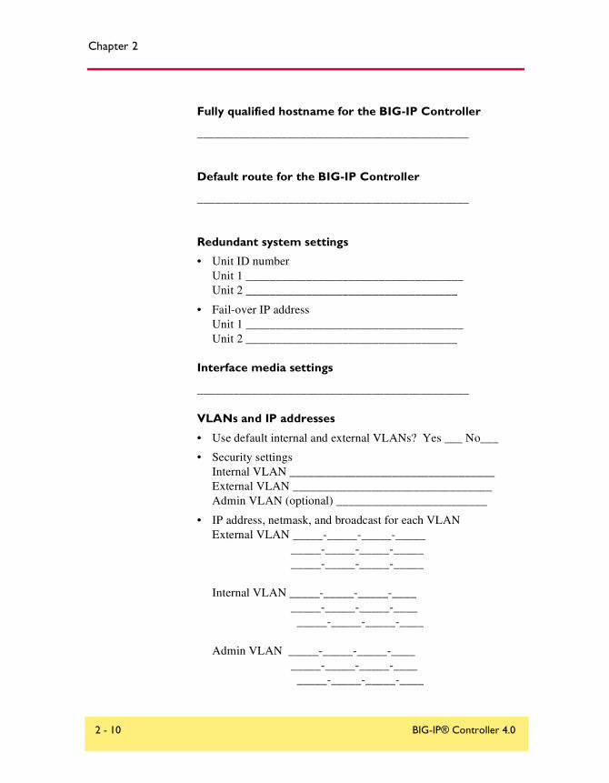
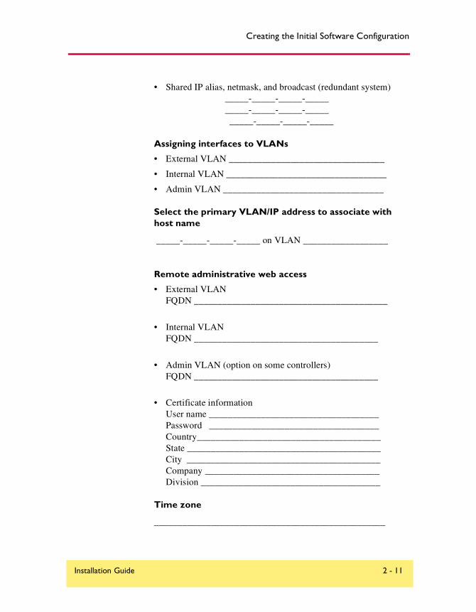
First-Time Boot utility configuration list
The following list outlines the settings that the First-Time Boot utility prompts you to enter. For detailed information about these settings, see the previous section.
Type of keyboard
_____________________________________________
Root password for the BIG-IP Controller
_____________________________________________
Installation Guide 2 - 9
Chapter 2
Fully qualified hostname for the BIG-IP Controller
_____________________________________________
Default route for the BIG-IP Controller
_____________________________________________
Redundant system settings
• Unit ID numberUnit 1 ____________________________________Unit 2 ___________________________________
• Fail-over IP addressUnit 1 ____________________________________Unit 2 ___________________________________
Interface media settings
_____________________________________________
VLANs and IP addresses
• Use default internal and external VLANs? Yes ___ No___
• Security settingsInternal VLAN __________________________________External VLAN _________________________________Admin VLAN (optional) _________________________
• IP address, netmask, and broadcast for each VLANExternal VLAN _____-_____-_____-_____ _____-_____-_____-_____ _____-_____-_____-_____
Internal VLAN _____-_____-_____-____ _____-_____-_____-____ _____-_____-_____-____
Admin VLAN _____-_____-_____-____ _____-_____-_____-____ _____-_____-_____-____
2 - 10 BIG-IP® Controller 4.0
Creating the Initial Software Configuration
• Shared IP alias, netmask, and broadcast (redundant system) _____-_____-_____-_____ _____-_____-_____-_____ _____-_____-_____-_____
Assigning interfaces to VLANs
• External VLAN _________________________________
• Internal VLAN __________________________________
• Admin VLAN __________________________________
Select the primary VLAN/IP address to associate with host name
_____-_____-_____-_____ on VLAN __________________
Remote administrative web access
• External VLANFQDN _________________________________________
• Internal VLANFQDN _______________________________________
• Admin VLAN (option on some controllers)FQDN _______________________________________
• Certificate informationUser name ____________________________________Password ____________________________________Country_______________________________________State _________________________________________City _________________________________________Company _____________________________________Division ______________________________________
Time zone
_________________________________________________
Installation Guide 2 - 11

Chapter 2
DNS forwarding proxy settings
DNS server_________________________________________
Fully qualified domain name (FQDN)______________________
Remote administrative command line access (single IP or multiple IPs)
_____-_____-_____-_____
Configure NTP support
Public clock server(s)_______________________________
3-DNS software module settings (optional)
Configure NameSurferUser name _______________________________________Password ________________________________________Set NameSurfer as master zone file_____________________
Starting the First-Time Boot utilityThe First-Time Boot utility prompts you to enter the same information, whether you run the utility from a web browser, or from the command line. When the utility completes we recommend that you reboot the controller. This automatically removes the default IP address and root password provided specifically for the purposes of running the First-Time Boot utility remotely. The BIG-IP Controller replaces the default IP address and root password with the password and IP addresses that you define while running the utility.
Running the utility from the console or serial terminal
Before you can run the First-Time Boot utility from either the console or a serial terminal, you must first login. Use the following default user name and password to login.
2 - 12 BIG-IP® Controller 4.0
Creating the Initial Software Configuration
Username: root
Password: default
After you login, you can start the utility directly from the console or serial terminal by typing the command config. Once you complete the utility, we recommend that you reboot the BIG-IP Controller.
Note
If you want to set up a terminal connection directly to the BIG-IP Controller, see Using a serial terminal with the BIG-IP Controller, on page 3-14.
Running the utility remotely
You can run the First-Time Boot utility remotely only from a workstation that is on the same LAN as the controller. To allow remote connections for the First-Time Boot utility, the BIG-IP Controller comes with two pre-defined IP addresses, and a pre-defined root password. The default root password is default, and the preferred default IP address is 192.168.1.245. If this IP address is unsuitable for your network, the BIG-IP Controller uses an alternate IP address, 192.168.245.245. However, if you define an IP alias on an administrative workstation in the same IP network as the BIG-IP Controller, the controller detects the network of the alias and uses the corresponding default IP address.
Once the utility finishes and the system reboots, these default IP addresses and root password are replaced by the information that you entered in the First-Time Boot utility.
Setting up an IP alias for the default IP address before you start the controller
You must set up an IP alias for your remote workstation before you turn on the controller and start the First-Time Boot utility. The remote workstation must be on the same IP network as the controller. If you add this alias prior to booting up the BIG-IP Controller, the controller detects the alias and uses the corresponding address.
Installation Guide 2 - 13
Chapter 2
To set up an IP alias for the alternate IP address
The IP alias must be in the same network as the default IP address you want the BIG-IP Controller to use. For example, on a UNIX workstation, you might create one of the following aliases:
◆ If you want the controller to use the default IP address 192.168.1.245, then add an IP alias to the machine you want to use to connect to the controller using the following command:
ifconfig exp0 add 192.168.1.1
◆ If you want to use the default IP address 192.168.245.245, then add an IP alias such as:
ifconfig exp0 add 192.168.245.1
WARNING
On Microsoft Windows or Windows NT machines you must use a static IP address, not DHCP. Within the network configuration, add an IP alias in the same network as the IP in use on the controller. For information about adding a static IP address to a Microsoft Windows operating system, please refer to your vendor’s documentation.
Determining which default IP address is in use
After you configure an IP alias on the administrative workstation in the same IP network as the BIG-IP Controller and you turn the system on, the BIG-IP Controller sends ARPs on the internal VLAN to see if the preferred 192.168.1.245 IP address is in use. If the address is appropriate for your network and is currently available, the BIG-IP Controller assigns it to the internal VLAN. You can immediately use it to connect to the controller and start the First-Time Boot utility.
If the alternate network is present on the LAN, 192.168.245.0/24, or if the node address 192.168.1.245 is in use, then the BIG-IP Controller assigns the alternate IP address 192.168.245.245 to the internal VLAN instead.
2 - 14 BIG-IP® Controller 4.0

Creating the Initial Software Configuration
Starting the utility from a web browser
When you start the utility from a web browser, you use the selected default IP address as the application URL.
To start the First-Time Boot utility in a web browser
1. Open a web browser on a workstation connected to the same IP network as the internal VLAN of the controller.
2. Type the following URL, where <default IP> is the IP address in use on the BIG-IP Controller internal VLAN.https://<default IP>
3. At the login prompt, type root for the user name, and default for the password.The Configuration Status screen opens.
4. On the Configuration Status screen, click Start Wizard.
5. Fill out each screen using the information from the First-Time Boot utility configuration list. After you complete the First-Time Boot utility, the BIG-IP Controller reboots and uses the new settings you defined.
Note
You can rerun the First-Time Boot utility from a web browser at any time by clicking the First-Time Boot utility link on the home screen.
Starting the utility from the command line
You can run the command line version of the First-Time Boot utility from a remote SSH client or from a Telnet client.
To start the First-Time Boot utility from the command line
1. Start an SSH client on a workstation connected to the same IP network as the internal VLAN of the controller. (See Downloading the SSH client to your administrative workstation, on page 3-3, for information on downloading the SSH client from the BIG-IP Controller.)
Installation Guide 2 - 15
Chapter 2
2. Type the following command, where <default IP> is the IP address in use on the BIG-IP Controller internal VLAN.ssh <default IP>
3. At the login prompt, type root for the user name, and default for the password.
4. At the BIG-IP Controller prompt, type the following command to start the command-line based First-Time Boot utility.config
5. Fill out each screen using the information from the First-Time Boot utility configuration list. After you complete the First-Time Boot utility, the BIG-IP Controller reboots and uses the new settings you defined.
Note
You can rerun the First-Time Boot utility at any time using the config command. For more information about rerunning this utility, refer to the BIG-IP Reference Guide.
2 - 16 BIG-IP® Controller 4.0
3
Additional Setup Options
• Overview of additional setup options
• Defining additional host names
• Downloading the SSH client to your administrative workstation
• Addressing general networking issues
• Using a serial terminal with the BIG-IP Controller
• Configuring RADIUS authentication
Additional Setup Options
Overview of additional setup optionsThis chapter contains details about additional setup options you may want to configure for the controller. The options described in this chapter include:
• Defining additional host names
• Preparing workstations for command line access
• Addressing general networking issues
• Using a serial terminal with the BIG-IP Controller
• Configuring RADIUS authentication
Defining additional host namesOnce you complete the First-Time Boot utility, you may want to insert additional host names and IP addresses for network devices into the /etc/hosts file to allow for more user-friendly system administration. In particular, you may want to create host names for the IP addresses that you will assign to virtual servers. You may also want to define host names for standard devices such as your routers, network interface cards, and the servers or other equipment that you are load balancing.
Installation Guide 3 - 1
Chapter 3
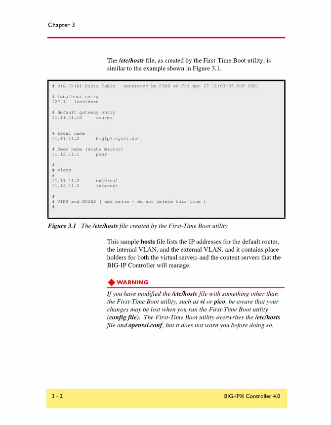
The /etc/hosts file, as created by the First-Time Boot utility, is similar to the example shown in Figure 3.1.
This sample hosts file lists the IP addresses for the default router, the internal VLAN, and the external VLAN, and it contains place holders for both the virtual servers and the content servers that the BIG-IP Controller will manage.
WARNING
If you have modified the /etc/hosts file with something other than the First-Time Boot utility, such as vi or pico, be aware that your changes may be lost when you run the First-Time Boot utility (config file). The First-Time Boot utility overwrites the /etc/hosts file and openssl.conf, but it does not warn you before doing so.
# BIG-IP(R) Hosts Table Generated by FTBU on Fri Apr 27 11:03:03 PDT 2001
# localhost entry127.1 localhost
# default gateway entry11.11.11.10 router
# Local name11.11.11.2 bigip1.mynet.net
# Peer name (state mirror)11.12.11.1 peer
## vlans#11.11.11.2 external11.12.11.2 internal ## VIPS and NODES ( add below - do not delete this line )#
Figure 3.1 The /etc/hosts file created by the First-Time Boot utility
3 - 2 BIG-IP® Controller 4.0

Additional Setup Options
Downloading the SSH client to your administrative workstation
From BIG-IP Controllers that support encrypted communications, you can download the SSH client to your administrative workstation in preparation for remote command line access. In addition to running BIG-IP command line utilities, you can also use the SSH suite for file transfer to and from the BIG-IP Controller, as well as for remote backups.
The SSH client is available for both Windows and UNIX platforms, and you can download your preferred client either from the web server or using an FTP connection. You can find detailed information about the SSH client in the F-Secure SSH manual, provided with your BIG-IP Administrator Kit.
Note
If your BIG-IP Controller does not support encrypted connections, you can use a Telnet shell for remote command line access.
WARNING
The F-Secure SSH license agreement allows you to use two copies of the F-Secure SSH client. If you require additional licenses, you need to contact Data Fellows. For information about contacting Data Fellows, as well as information about working with the SSH client, refer to the F-Secure manual included with your BIG-IP Controller.
Downloading the F-Secure SSH client from the web server
Connect to the controller using https:// rather than http:// in the URL. In the Additional Software Downloads section, click the SSH Clients link. From the SSH Clients page, you can choose the SSH Client appropriate to your operating system.
Installation Guide 3 - 3
Chapter 3
Setting up the F-Secure SSH client on a Windows 95 or Windows NT workstation
The F-Secure SSH client installation file for Windows platforms is compressed in ZIP format. You can use standard ZIP tools, such as PKZip or WinZip to extract the file.
To unzip and install the SSH client
1. Log on to the Windows workstation.
2. Navigate to the directory to which you transferred the F-Secure installation file. Run PKZip or WinZip to extract the files.
3. The set of files extracted includes a Setup program. Run the Setup program to install the client.
4. Start the F-Secure SSH client.
5. In the SSH Client window, from the Edit menu choose Properties. The Properties dialog box opens.
6. In the Connection tab, in the Remote Host section, type the following items:
• In the Host Name box, type the BIG-IP Controller IP address or host name.
• In the User Name box, type the root user name.
7. In the Options section, check Compression and set the Cipher option to Blowfish.
8. Click the OK button.
Setting up the F-Secure SSH client on a UNIX workstation
The F-Secure installation file for UNIX platforms is compressed in tar/gzip format.
3 - 4 BIG-IP® Controller 4.0
Additional Setup Options
To untar and install the SSH client
1. Log on to the workstation and navigate to the directory into which you transferred the F-Secure SSH client tar file.
2. Untar the file and follow the instructions in the install file to build the F-Secure SSH client for your workstation.
3. Start the SSH client.
4. Open a connection to the BIG-IP Controller:
ssh -l root [BIG-IP IP address]
5. Type the root password and press the Enter key.
Addressing general networking issuesYou must address several network issues when you place a BIG-IP Controller in your network. These networking issues include routing, DNS configuration, and special e-mail considerations. You need to address these issues based on the type of hardware and software in your network. This section describes the following networking issues:
◆ Addressing routing issuesThere are a variety of routing configuration issues that you need to address. If you did not create a default route with the First-Time Boot utility, you must now configure a default route for the BIG-IP Controller. You also must set up routes for the nodes that the BIG-IP Controller manages. You may also want to configure GateD, which allows dynamic routing information to automatically be updated on the BIG-IP Controller.
◆ Configuring DNS on the BIG-IP ControllerYou may need to configure the BIG-IP Controller for DNS resolution or for DNS proxy, and you may even need to convert from rotary or round robin DNS.
◆ Configuring email on the BIG-IP ControllerThere are some special requirements that you need to take into account when configuring email on the BIG-IP Controller.
Installation Guide 3 - 5
Chapter 3
Addressing routing issues
The BIG-IP Controller must communicate properly with network routers, as well as with the servers, firewalls, and other routers that it manages. Because there is a variety of router configurations, and varying levels of direct control an administrator has over each router, you need to carefully review the router configurations in your own network. You may need to change some routing configurations before you put the BIG-IP Controller into production.
The BIG-IP Controller supports static route configurations, dynamic routing (via BGP4, RIP1, RIP2, and OSPF), and subnetting. However, the BIG-IP Controller is also designed to eliminate the need for you to modify routing tables on a router that routes to a BIG-IP Controller. Instead, the BIG-IP Controller uses Address Resolution Protocol (ARP) to notify routers of the IP addresses that it uses on each interface, as well as on its virtual servers.
The following sections address these common routing issues:
• Routing from a BIG-IP Controller to a gateway to the external network
• Routing from content servers to the BIG-IP Controller
• Routing between a BIG-IP Controller to content servers that are on different logical networks
• Setting up dynamic routing with GateD
Routing from a BIG-IP Controller to a gateway to the external net
The BIG-IP Controller needs a route to the external network. For most configurations, this should be configured as the default route on the BIG-IP Controller.
During installation, you were prompted to configure a default route for the BIG-IP Controller. If you need to change the default route at this time, you can set a new default route by editing the /etc/hosts file.
3 - 6 BIG-IP® Controller 4.0

Additional Setup Options
To change the default route
1. Open the /etc/hosts file in a text editor, such as vi or pico.
2. Change the default gateway entry using the following syntax, where <router IP> is the IP address of the router:
<router IP> router
3. Save and close the file.
4. Reboot the BIG-IP Controller.
Routing from content servers to the BIG-IP Controller
The content servers being load balanced by the BIG-IP Controller need to have a default route set to the internal IP alias (source processing) of the BIG-IP Controller. For most configurations, this should be configured as the default route on the content server.
For information about setting the default route for your content servers, refer to the product documentation for your server.
Routing between a BIG-IP Controller and content servers on different logical networks
If you need to configure the BIG-IP Controller to use one or more nodes that actually sit on a different logical network from the BIG-IP Controller, you need to assign one or more additional routes to get to those nodes. Set each node’s default route so that traffic goes back through the BIG-IP Controller internal interface.
In the following examples, the nodes are on 192.168.6.0/24 and the BIG-IP Controller internal interface is on 192.168.5.0/24. There are two possible situations which you may have to address:
• 192.168.5.0/24 and 192.168.6.0/24 are on the same LAN (either sharing media or with a switch or hub between them).
• 192.168.5.0/24 and 192.168.6.0/24 are on two different LANs with a router between them.
Installation Guide 3 - 7

Chapter 3
Case 1: Same LAN
If the nodes are on the same LAN as the BIG-IP Controller, you simply need to add an interface route for 192.168.6.0/24 to the BIG-IP Controller's internal interface. You can add this route to the bottom of the /etc/rc.local file using the following syntax, where <ip addr> is the IP address on the internal interface:route add -net 192.168.6 -interface <ip addr>
Note
You must have the interface defined correctly in the /etc/hosts file in order to use this syntax.
Case 2: Different LANs
If you have nodes on different LANs from the BIG-IP Controller, you need to add a static gateway route on the BIG-IP Controller itself. If, for example, the router that connects the 192.168.5 network and the 192.168.6 network has IP addresses: 192.168.5.254 and 192.168.6.254, then you could use the following command to create the necessary static route on the BIG-IP Controller: route add -net 192.168.6.0 -gateway 192.168.5.254
You should add this command to the end of the file /etc/netstart so that it runs each time the BIG-IP Controller boots.
You may also need to set the default route on the nodes to point to the router between the LANs. For example:route add default -gateway 192.168.6.254
Finally, you need to set the default route on the router between the LANs to the BIG-IP Controller's shared alias. For example, type the command:route add default -gateway 192.168.5.200
Note
These examples assume you are using a UNIX-based router. The exact syntax for your router may be different.
3 - 8 BIG-IP® Controller 4.0

Additional Setup Options
It is not necessary to set the default route for nodes directly to the BIG-IP Controller, as long as the default path eventually routes through the BIG-IP Controller.
Setting up dynamic routing with GateD
The GateD daemon allows the BIG-IP Controller to exchange dynamic routing updates with your routers. Setting up the GateD daemon is a three-part task:
• You need to create the GateD configuration file, /config/gated.conf.
• You need to start the GateD daemon.
• You need to edit the /etc/netstart file.
Tip
You are not required to configure GateD on the BIG-IP Controller. The BIG-IP Controller can meet most routing requirements without using GateD.
Note
Additional documentation for GateD is available through the web server on the BIG-IP Controller.
To create the GateD configuration file
GateD relies on a configuration file, typically named /config/gated.conf, which can be relatively simple, or can be very complex, depending on the routing needs of your network. The BIG-IP web server includes the GateD online documentation (in the Configuration utility home screen, under the Online Documentation section, click GateD). Note that the GateD configuration guide details the process of creating the GateD configuration file, and also provides samples of common protocol configurations.
Installation Guide 3 - 9
Chapter 3
To immediately start the GateD daemon on the BIG-IP Controller
Once you create the GateD configuration file, you need to start the GateD daemon on the command line using the following command:bigip# gated
Configuring DNS on the BIG-IP Controller
If you plan to use DNS in your network, you can configure DNS on the BIG-IP Controller. There are three different DNS issues that you may need to address when setting up the BIG-IP Controller:
• Configuring DNS resolution on the BIG-IP Controller
• Configuring DNS proxy
• Converting from rotary or round robin DNS
Configuring DNS resolution
When entering virtual addresses, node addresses, or any other addresses on the BIG-IP Controller, you can use the address, host name, or fully qualified domain name (FQDN).
The BIG-IP Controller looks up host names and FQDNs in the /etc/hosts file. If it does not find an entry in that file, then it uses DNS to look up the address. In order for this to work, you need to create an /etc/resolv.conf file. The file should have the following format:nameserver <DNS_SERVER_1>
search <DOMAIN_NAME_1> <DOMAIN_NAME_2>
In place of the <DNS_SERVER_1> parameter, use the IP address of a properly configured name server that has access to the Internet. You can specify additional name servers as backups by inserting an additional nameserver line for each backup name server.
If you configure the BIG-IP Controller itself as a DNS proxy server, then we suggest that you choose its loopback address (127.0.0.1) as the first name server in the /etc/resolv.conf file.
3 - 10 BIG-IP® Controller 4.0
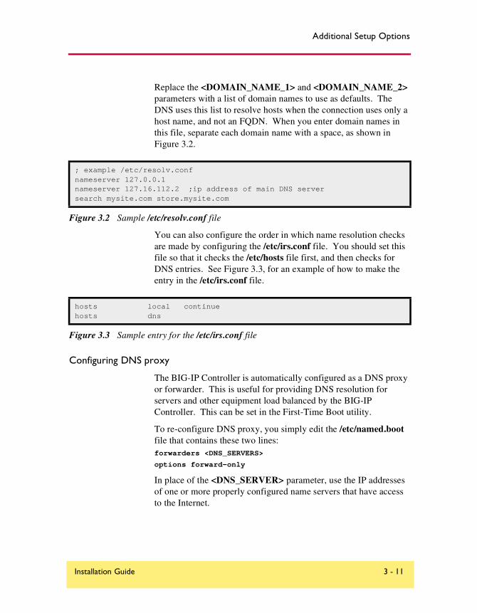
Additional Setup Options
Replace the <DOMAIN_NAME_1> and <DOMAIN_NAME_2> parameters with a list of domain names to use as defaults. The DNS uses this list to resolve hosts when the connection uses only a host name, and not an FQDN. When you enter domain names in this file, separate each domain name with a space, as shown in Figure 3.2.
You can also configure the order in which name resolution checks are made by configuring the /etc/irs.conf file. You should set this file so that it checks the /etc/hosts file first, and then checks for DNS entries. See Figure 3.3, for an example of how to make the entry in the /etc/irs.conf file.
Configuring DNS proxy
The BIG-IP Controller is automatically configured as a DNS proxy or forwarder. This is useful for providing DNS resolution for servers and other equipment load balanced by the BIG-IP Controller. This can be set in the First-Time Boot utility.
To re-configure DNS proxy, you simply edit the /etc/named.boot file that contains these two lines:forwarders <DNS_SERVERS>
options forward-only
In place of the <DNS_SERVER> parameter, use the IP addresses of one or more properly configured name servers that have access to the Internet.
; example /etc/resolv.confnameserver 127.0.0.1nameserver 127.16.112.2 ;ip address of main DNS serversearch mysite.com store.mysite.com
Figure 3.2 Sample /etc/resolv.conf file
hosts local continuehosts dns
Figure 3.3 Sample entry for the /etc/irs.conf file
Installation Guide 3 - 11

Chapter 3
You can also configure the BIG-IP Controller to be an authoritative name server for one or more domains. This is useful when DNS is needed in conjunction with internal domain names and network addresses for the servers and other equipment behind the BIG-IP Controller. Refer to the BIND documentation for more details.
Converting from rotary or round robin DNS
If your network is currently configured to use rotary DNS, your node configuration may not need modification. However, you need to modify your DNS zone tables to map to a single IP address instead of to multiple IP addresses.
For example, if you had two Web sites with domain names of www.SiteOne.com and www.SiteTwo.com, and used rotary DNS to cycle between two servers for each Web site, your zone table might look like the one in Figure 3.4.
In the BIG-IP Controller configuration, the IP address of each individual node used in the original zone table becomes hidden from the Internet. We recommend that you use the Internet reserved address range as specified by RFC 1918 for your nodes. In place of multiple addresses, simply use a single virtual server associated with your site's domain name.
Using the above example, the DNS zone table might look like the zone table shown in Figure 3.5.
www.SiteOne.com IN A 192.168.1.1 IN A 192.168.1.2www.SiteTwo.com IN A 192.168.1.3 IN A 192.168.1.4
Figure 3.4 Sample zone table with two Web sites and four servers
www.SiteOne.com IN A 192.168.100.231www.SiteTwo.com IN A 192.168.100.232
Figure 3.5 Sample zone table with two Web sites and two servers.
3 - 12 BIG-IP® Controller 4.0
Additional Setup Options
Configuring email
Another optional feature you can set up when you configure the BIG-IP Controller is email. You can configure the BIG-IP Controller to send email notifications to you, or to other administrators. The BIG-IP Controller uses Sendmail as its mail transfer agent. The BIG-IP Controller includes a sample Sendmail configuration file that you can use to start with, but you will have to customize the Sendmail setup for your network environment before you can use it.
Before you begin setting up Sendmail, you may need to look up the name of the mail exchanger for your domain. If you already know the name of the mail exchanger, continue with the following section, Setting up Sendmail.
Setting up Sendmail
When you actually set up Sendmail, you need to open and edit a couple of configuration files. Note that the BIG-IP Controller does not accept email messages, and that you can use the crontab utility to purge unsent or returned messages, and that you can send those messages to yourself or another administrator.
To set up and start Sendmail
1. Copy /config/sendmail.cf.off to /config/sendmail.cf.
2. To set the name of your mail exchange server, open the /config/sendmail.cf and set the DS variable to the name of your mail exchanger. The syntax for this entry is:
DS<MAILHUB_OR_RELAY>
3. Save and close the /config/sendmail.cf file.
4. If you want to allow Sendmail to flush outgoing messages from the queue for mail that cannot be delivered immediately:
a) Open the /config/crontab file, and change the last line of the file to read:0,15,30,45 * * * * root /usr/sbin/sendmail -q > /dev/null 2>&1
Installation Guide 3 - 13
Chapter 3
b) Save and close the /config/crontab file.
5. If you want to prevent returned or undelivered email from going unnoticed:
a) Open the /config/aliases file and create an entry for root to point to you or another administrator at your site:root: [email protected]
b) Save and close the /config/aliases file.
c) Run the newaliases command to generate a new aliases database that incorporates the information you added to the /config/aliases file.
6. To turn Sendmail on, either reboot the system or type the following command:
/usr/sbin/sendmail -bd -q30m
Using a serial terminal with the BIG-IP Controller
There are a couple of different ways to add a serial terminal to the BIG-IP Controller. You can add a serial terminal in addition to the console, or you can add a serial terminal as the console. The difference between the two is:
• A serial terminal configured as a terminal displays a simple login. You can log in and run commands and edit files. In this case, you can use the serial terminal in addition to the keyboard and monitor.
• A serial terminal configured as the console displays system messages and warnings in addition to providing a login prompt. In this case, the serial terminal replaces the keyboard and monitor.
3 - 14 BIG-IP® Controller 4.0
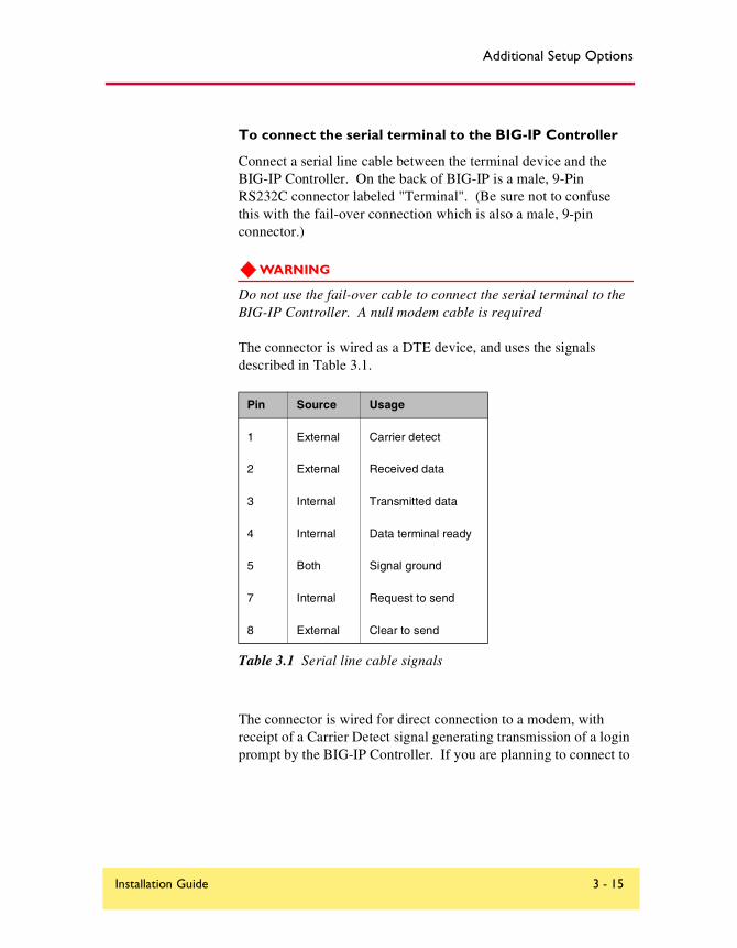
Additional Setup Options
To connect the serial terminal to the BIG-IP Controller
Connect a serial line cable between the terminal device and the BIG-IP Controller. On the back of BIG-IP is a male, 9-Pin RS232C connector labeled "Terminal". (Be sure not to confuse this with the fail-over connection which is also a male, 9-pin connector.)
WARNING
Do not use the fail-over cable to connect the serial terminal to the BIG-IP Controller. A null modem cable is required
The connector is wired as a DTE device, and uses the signals described in Table 3.1.
The connector is wired for direct connection to a modem, with receipt of a Carrier Detect signal generating transmission of a login prompt by the BIG-IP Controller. If you are planning to connect to
Pin Source Usage
1 External Carrier detect
2 External Received data
3 Internal Transmitted data
4 Internal Data terminal ready
5 Both Signal ground
7 Internal Request to send
8 External Clear to send
Table 3.1 Serial line cable signals
Installation Guide 3 - 15

Chapter 3
a terminal or to connect a PC and utilize a terminal emulation program such as HyperTerminal™, you will need a null modem cable with the wiring to generate the signals shown in Table 3.1.
Note
You can achieve acceptable operation by wiring pins 7 to 8 and pins 1 to 4 at the back of BIG-IP Controller (and turning hardware flow control off in your terminal or terminal emulator).
Configuring a serial terminal in addition to the console
You can configure a serial terminal for the BIG-IP Controller in addition to the standard console.
To configure the serial terminal in addition to the console
1. Connect the serial terminal to the BIG-IP Controller.
2. Configure the serial terminal settings in your terminal or terminal emulator or modem as follows:
• 9600 baud
• 8 bits
• 1 stop bit
• No parity
3. Open the /etc/ttys file and find the line that reads tty00 off. Modify it as shown here:
# PC COM ports (tty00 is DOS COM1)
tty00 "/usr/libexec/getty default" vt100 in secure
4. Save the /etc/ttys file and close it.
5. Reboot the BIG-IP Controller.
Configuring a serial terminal as the console
You can configure the serial terminal as the console.
3 - 16 BIG-IP® Controller 4.0
Additional Setup Options
To configure the serial terminal as the console
1. Disconnect the keyboard from the BIG-IP Controller.
2. Connect the serial terminal to the BIG-IP Controller. When there is no keyboard connected to the BIG-IP Controller, the BIG-IP Controller defaults to using the serial port for the console.
3. Configure the serial terminal settings in your terminal or terminal emulator or modem as follows:
• 9600 baud
• 8 bits
• 1 stop bit
• No parity
4. Reboot the BIG-IP Controller.
Forcing a serial terminal to be the console
In the case where you have not yet connected the serial terminal or it is not active when the BIG-IP Controller is booted, as it might be if you are using a terminal server or dial-up modem, you can force the controller to use the serial terminal as a console. Note that you do not need to disconnect the keyboard if you use this procedure to force the serial line to be the console.
To force a serial terminal to be the console
1. Edit the /etc/boot.default file.Find the entry -console auto. Change this entry to -console com.
2. Save the /etc/boot.default file and exit the editor.
3. Plug the serial terminal into the serial port on the BIG-IP Controller.
Installation Guide 3 - 17
Chapter 3
4. Turn on the serial terminal.
5. Reboot the controller.
WARNING
Once you configure a serial terminal as the console for the BIG-IP Controller, the following conditions apply:
Keyboard/monitor access is disabled, and logging in is only possible via Secure Telnet (SSH), if configured, or the serial line.
If the boot.default file is corrupted, the system will not boot at all. Save a backup copy of the original file and keep a bootable CD-ROM on hand.
The boot.default file must contain either the line: "-console com" or the line: "-console auto".
Configuring RADIUS authenticationYou can configure the BIG-IP Controller to use a RADIUS server on your network to authenticate users attempting to access the controller with SSH. In this configuration, the RADIUS server can function as a central repository of users that are allowed access to the BIG-IP Controller for administrative purposes.
To do this, configure the BIG-IP Controller to act as a Network Access Server (NAS) for a RADIUS server in your network. When you set up this feature, client connections received by the BIG-IP Controller for users not listed in the local account database
3 - 18 BIG-IP® Controller 4.0

Additional Setup Options
are routed to the RADIUS server to be authenticated. If the user is authenticated, the user is logged in as the BIG-IP Controller user that you specify in the RADIUS user setting.
Note
RADIUS authentication through the BIG-IP Controller is based on the username/password only. It does not support challenge-response authentication methods.
You can configure the BIG-IP Controller to use either version 1.x or version 2.x, or both, of the sshd for SSH authentication.
Tip
If you want to support only SSH version 1.x clients, configure sshd version 1.x. Do not configure sshd version 2.x. However, if you want to support version 1.x and version 2.x clients, configure sshd version 2.x.
Using RADIUS ports on the BIG-IP Controller
The BIG-IP Controller uses the ports 1645/udp for communicating with the RADIUS server. If your RADIUS server uses different ports, such as 1812/udp, you must change the ports used by the BIG-IP Controller to these ports. To do this, use a text editor such as vi or pico to change the existing RADIUS port entry in the /etc/services file on each BIG-IP Controller. Figure 3.6 shows a sample file.
radius 1812/tcp # Radius radacct 1813/udp # Radius Accounting
Figure 3.6 Alternative ports on the BIG-IP Controller for the RADIUS server
Installation Guide 3 - 19

Chapter 3
Configuring sshd version 2.x
You can configure version 2.x of the sshd by editing the /etc/ssh2/sshd2_config on the BIG-IP Controller with pico or vi. The following entries must be in the sshd2_config file:
◆ RadiusServerThis entry is the host name or IP address of the RADIUS server.
◆ RadiusKeyThis entry is the shared secret key of the RADIUS server. This key should be at least 16 characters long.
◆ RadiusNasIPThis is the host name or IP address of the interface on the BIG-IP Controller connected to the network that hosts the RADIUS server. Note that you can only use interfaces set to admin port open for RADIUS authentication.
◆ RadiusUserThis entry is the user name of the local BIG-IP Controller user, such as root. When the RADIUS user is authenticated, the user is logged into the controller as this user.
Note
The most secure method for using RADIUS with the BIG-IP Controller is to create a RadiusUser entry that has a low level of privileges. After you are authenticated and you log in to the BIG-IP Controller as the low privilege user, use the su command to gain root privileges.
3 - 20 BIG-IP® Controller 4.0
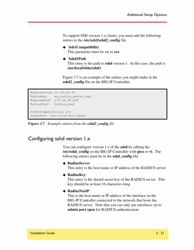
Additional Setup Options
To support SSH version 1.x clients, you must add the following entries to the /etc/ssh2/sshd2_config file.
◆ Ssh1CompatibilityThis parameter must be set to yes.
◆ Sshd1PathThis entry is the path to sshd version 1. In this case, the path is /usr/local/sbin/sshd1.
Figure 3.7 is an example of the entries you might make in the sshd2_config file on the BIG-IP Controller.
Configuring sshd version 1.x
You can configure version 1.x of the sshd by editing the /etc/sshd_config on the BIG-IP Controller with pico or vi. The following entries must be in the sshd_config file:
◆ RadiusServerThis entry is the host name or IP address of the RADIUS server.
◆ RadiusKeyThis entry is the shared secret key of the RADIUS server. This key should be at least 16 characters long.
◆ RadiusNasIPThis is the host name or IP address of the interface on the BIG-IP Controller connected to the network that hosts the RADIUS server. Note that you can only use interfaces set to admin port open for RADIUS authentication.
RadiusServer 12.34.56.78RadiusKey my_radius_server.keyRadiusNasIP 172.16.42.200RadiusUser radius_user
Sshd1Compatibility yesSshd1Path /usr/local/bin/sshd1
Figure 3.7 Example entries from the sshd2_config file
Installation Guide 3 - 21
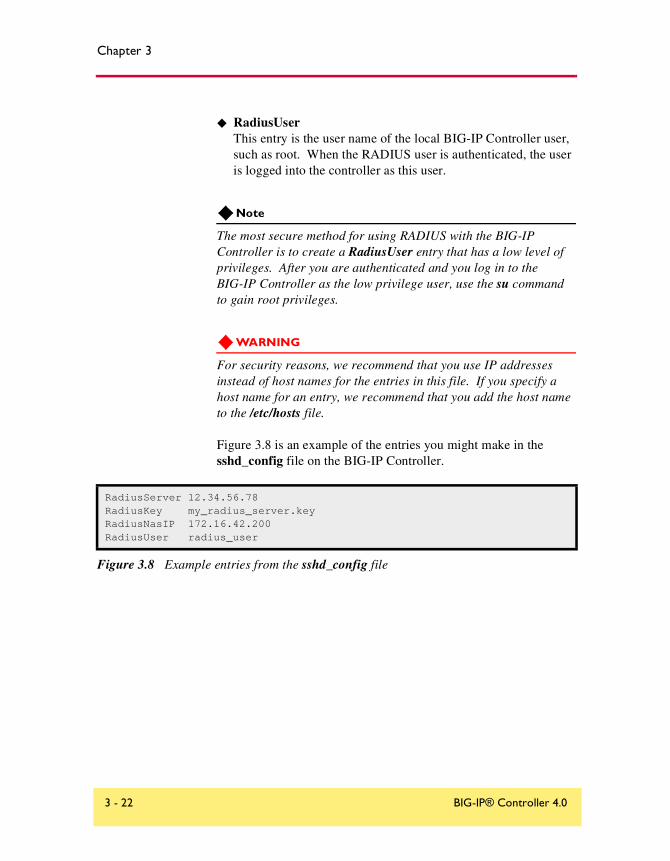
Chapter 3
◆ RadiusUserThis entry is the user name of the local BIG-IP Controller user, such as root. When the RADIUS user is authenticated, the user is logged into the controller as this user.
Note
The most secure method for using RADIUS with the BIG-IP Controller is to create a RadiusUser entry that has a low level of privileges. After you are authenticated and you log in to the BIG-IP Controller as the low privilege user, use the su command to gain root privileges.
WARNING
For security reasons, we recommend that you use IP addresses instead of host names for the entries in this file. If you specify a host name for an entry, we recommend that you add the host name to the /etc/hosts file.
Figure 3.8 is an example of the entries you might make in the sshd_config file on the BIG-IP Controller.
RadiusServer 12.34.56.78RadiusKey my_radius_server.keyRadiusNasIP 172.16.42.200RadiusUser radius_user
Figure 3.8 Example entries from the sshd_config file
3 - 22 BIG-IP® Controller 4.0

Index

Index
/config/aliases 3-14/config/gated.conf 3-9/config/sendmail.cf 3-13/etc/hosts file 3-1, 3-2, 3-11/etc/irs.conf file 3-11/etc/resolv.conf file 3-102U hardware 1-63-DNS module
NameSurfer 2-93-DNS software module Intro-34U hardware 1-3
Aactive-active configurations, unit ID numbers 2-4Address Resolution Protocol (ARP) 3-6administrative access
IP addresses allowed 2-8, 2-12support account 2-8
Administrator Kit, description Intro-2authoritative name servers 3-12
BBIG-IP Cache Controller, selecting 2-2BIG-IP Controller product family Intro-10BIG-IP Fire Guard, selecting 2-2BIG-IP Load Balancer, selecting 2-2bigpipe utility Intro-2bigtop utility Intro-2browser, supported versions Intro-2
Ccable, fail-over 1-1certificates, configuration information 2-6, 2-11command line access 3-5config command, First-Time Boot utility 2-13Configuration utility, web-based Intro-1connections, administrative 2-8content servers
adding to hosts file 3-2default route 2-5, 3-7
DData Fellows 3-3DC powered equipment guidelines 1-9default configuration
user name 2-13default IP addresses
alternate address 2-13and IP alias 2-14overview 2-12preferred address 2-13
default root password 2-12default route
changing 3-6for content servers 3-7for external gateway 3-6setting 2-3, 2-10
DNS configurationconfiguring proxy 3-11converting from rotary 3-12converting from round robin 3-12forwarding proxy settings 2-7, 2-12resolving names 3-10–3-11zone tables 3-12
domain names 3-12
Eemail configuration 3-13–3-14encrypted communications 3-3environmental guidelines 1-7Ethernet hub requirements 1-2external VLAN 3-2
Ffail-over cable 1-1, 1-11fail-over IP address, setting 2-4, 2-10FDDI/CDDI requirements 1-2First-Time Boot utility
3-DNS module options 2-9, 2-12default IP address access 2-14default password 2-13defined Intro-1NTP support 2-9
Installation Guide Index - 1

Index
rerunning from a web browser 2-15rerunning from the command line 2-16running from a browser 2-15running from an ssh client 2-15running from the command line 2-15running from the console 2-13system settings defined 2-1
F-Secure SSH clientdocumentation 3-3downloading from the web server 3-3installing on UNIX 3-4installing on Windows 95 or NT 3-4license restrictions 3-3remote administration Intro-2
fully qualified domain name (FQDN) 2-6, 3-10
GGateD
configuration file 3-9documentation 3-9dynamic routing 3-9
Gigabit Ethernet 1-2Gigabit Ethernet requirements 1-2grounding hardware 1-8
Hhardware
2U configuration 1-64U configuration 1-3DC powered equipment 1-9environmental guidelines 1-7
hardware installationconnecting components 1-10planning 1-8
hardware requirementscomponents 1-1peripherals 1-2
host nameschanging 2-7controller host name 2-3, 2-10primary IP address 2-6primary VLAN association 2-11
hosts file, adding host names 3-1httpd.conf file 2-7hubs 1-2
Iinterface 2-4interface cards. See NICsinterface media settings 2-10internal VLAN 2-14, 3-2IP addresses
changing 2-7configuring default route 2-3configuring fail-over 2-4defining Intro-1for default configuration 2-13
IP alias, for default IP address 2-14
Kkeyboard adapter, PC/AT-to-PS/2 1-10keyboard lock 1-4, 1-6keyboard type setting 2-1keyboard type, setting 2-9
LLED indicators 2-5lithium battery 1-8load balancing
configuring Intro-1monitoring Intro-1
Mmedia settings 2-4MIB. See SNMP MIBmonitoring, command-line utilities Intro-2
Nname servers 3-12NameSurfer, configuring 2-12Network Access Server 3-18network adapters 2-5
Index - 2 BIG-IP® Controller 4.0

Index
Network Time Protocol (NTP) 2-9NICs, connecting 1-10NTP configuration
public clock server 2-12
Oopenssl.conf 2-7, 3-2
Ppassword 2-13
default configuration 2-13PC/AT-to-PS/2 keyboard adapter 1-10ports 1-3, 1-5, 1-7power cable 1-11product selection 2-2proxy, DNS. See DNS configuration
Rrack mounting 1-8RADIUS authentication
challenge-response authentication 3-19defined 3-18sshd version 1.x, configuring 3-21sshd version 2.x, configuring 3-20sshd version issues 3-19udp ports 3-19
reconfig_httpd utility 2-7redundant systems
active-active configurations 2-4choosing fail-over IP addresses 2-4fail-over cable 1-1fail-over IP address 2-4, 2-10floating self IP alias 2-5shared IP alias 2-11unit ID numbers, setting 2-4, 2-10
remote administration 1-2root password
defining Intro-1setting 2-2, 2-9
rotary DNS. See DNS configurationround robin 3-12router configurations
default 3-6examples 3-8from content servers 3-7on different logical networks 3-7overview 3-6with GateD 3-9
routers, host names 3-1
Sself IP address 2-5sendmail 3-13serial terminal
configured as console 3-14, 3-16configured as terminal 3-14configuring in addition to console 3-16forcing to be console 3-17hardware installation 1-2, 1-10
SNMP MIB Intro-2SSH client. See F-Secure SSH clientsshd 3-19switches 1-2
Ttechnical support Intro-6terminal. See serial terminaltime zone, configuring 2-7, 2-11
Uunit ID numbers 2-4utilities Intro-2
Vventilation 1-8VGA monitor and keyboard, connecting 1-10virtual servers, host names 3-1
Installation Guide Index - 3

Index
VLANsconfiguring in First-Time Boot utility 2-5,
2-10default IP address 2-14interfaces, assigning 2-5, 2-11self IP address 2-5
voltage 1-8
Wweb server access
adding user accounts 2-7changing passwords 2-7configuring 2-6, 2-11
workstation configuration 3-5
Index - 4 BIG-IP® Controller 4.0