big cajun ii coal c r (ccr) annual inspection...
TRANSCRIPT

BIG CAJUN II COAL COMBUSTION RESIDUAL (CCR) ANNUAL INSPECTION REPORT NRG Louisiana Generating, LLC (LaGen) NRG Energy, Inc. Baton Rouge, Louisiana Project Number 1005494026 January 2016 Prepared for: NRG Louisiana Generating, LLC (LaGen) NRG Energy, Inc. New Roads, LA 70760 Prepared by: CB&I Environmental & Infrastructure, Inc. 4171 Essen Lane Baton Rouge, LA 70809

Table of Contents ________________________________________________
1.0 INTRODUCTION ............................................................................................................................ 1-1 1.1 Background .......................................................................................................................... 1-1
2.0 OPERATING RECORDS REVIEW ................................................................................................. 2-1 2.1 Summary of Impoundment Construction .............................................................................. 2-1 2.2 Storm Water Management ................................................................................................... 2-2 2.3 Summary of Construction Activities ...................................................................................... 2-2 2.4 Review of Prior Inspections .................................................................................................. 2-2 2.5 Summary of CCR Volumes .................................................................................................. 2-3 2.6 Review of Remedial Actions from Prior Inspections ............................................................. 2-3
3.0 ANNUAL SITE INSPECTION .......................................................................................................... 3-1 3.1 Inspection Procedure ............................................................................................................ 3-1 3.2 Visual Signs of Distress or Malfunction ................................................................................ 3-1 3.3 Hydraulic Structures ............................................................................................................. 3-2
4.0 CONCLUSIONS .............................................................................................................................. 4-1 4.1 Changes in Geometry ........................................................................................................... 4-1 4.2 CCR Volume/ depth and elevation ....................................................................................... 4-1 4.3 Appearance of Actual or Potential Structural Weakness of CCR Units ................................ 4-1 4.4 Changes that may affect the stability or operation of the CCR Unit ...................................... 4-1
5.0 RECOMMENDATIONS ................................................................................................................... 5-1 6.0 PROFESSIONAL ENGINEER’S CERTIFICATION ........................................................................... 6-1
i January 2016

List of Figures ______________________________________________
Figure 1 Site Plan Layout List of Appendices __________________________________________
Appendix A Photo Log List of Acronyms ___________________________________________
CB&I CB&I Environmental & Infrastructure CCR Coal Combustion Residuals CFR Code of Federal Regulations LAC Louisiana Administrative Code LaGen Louisiana Generating, LLC, LPDES Louisiana Pollution Discharge Elimination System MSL Mean Sea Level Yd3 Cubic yards
ii January 2016

1.0 INTRODUCTION
Big Cajun II Power Plant (Big Cajun II), operated by Louisiana Generating, LLC (LaGen), a subsidiary of NRG Energy, Inc., is a coal-fired and natural gas fired power plant located in New Roads, Louisiana. The Disposal of Coal Combustion Residuals (CCR) from Electric Utilities final rule (the Rule) was issued by the United States Environmental Protection Agency (Title 40 of the Code of Federal Regulations §257 [40CFR Part 257]) and applies to this facility due to the disposal of CCR that is generated from the combustion of coal at the site. 40 CFR Part 257 addresses, in part, the management of CCR in regulated units, including all surface impoundments. Specific to Section §257.83(b) of the CCR Rule, new and existing CCR surface impoundments must be inspected on an annual basis by a qualified professional engineer. This report details the findings for the CCR Annual Inspection Report for the following regulated CCR Units at Big Cajun II:
• Fly Ash Unit • Bottom Ash Unit
Mr. Glen R. Landry, P.E., a qualified professional engineer with CB&I Environmental & Infrastructure (CB&I) conducted an on-site inspection of the above impoundments on October 6th 2015. The following report details the summary of findings of the first CCR Annual Inspection for Big Cajun II Generation Station.
As required, this report will be placed in Big Cajun II operating record per §257.105(g), notice the State Director per §257.106(g), and posted to a publicly accessible internet site per §257.107(g). This annual inspection report is considered completed when the inspection report has been placed in the facilities’ operating record by no later than January 18, 2016, per §257.105(g)(6). The deadline for completion of subsequent annual inspections is one year from the actual date of placement of the previous year’s report into the operating record.
1.1 Background The solid waste facilities at Big Cajun II are permitted under the Louisiana Solid Waste Regulations (LAC 3:VII), Permit Number P-0108R1 (Facility Identification Number GD-077-0583). The solid waste permitted surface impoundments at Big Cajun II include:
• Fly Ash Unit • Bottom Ash Unit • LPDES Primary and Secondary Treatment Basins • Rainfall Surge Pond
1-1 January 2016

With respect to the CCR surface impoundments, namely the Fly Ash and Bottom Ash Units, CB&I’s evaluation focused on the following items outlined in §257.83(b)(i-vii):
• A review of available information regarding the status and condition of the CCR unit, including, but not limited to, files in the operating record;
• A visual inspection of the CCR unit to identify signs of distress or malfunction; and • A visual inspection of any hydraulic structures underlying the base of the CCR unit.
CB&I preparation of the annual inspection report, as per §257.83(b) includes:
• Changes in geometry of the impounding structure since the previous annual report; • Location and type of existing instrumentation and maximum recorded readings; • The approximate minimum, maximum and present depth and elevation of the impounded
water and CCR since the previous annual inspection; • The storage capacity of the impounding structure at the time of the inspection; • The approximate volume of the impounded water and CCR at the time of the inspection; • Any appearances of an actual or potential structural weakness of the CCR unit, in
addition to any existing conditions that are disrupting or have the potential to disrupt the operation and safety of the CCR unit and appurtenant structures; and
• Any other change(s) which may have affected the stability or operation of the impounding structure since the previous annual inspection.
1-2 January 2016

2.0 OPERATING RECORDS REVIEW
2.1 Summary of Impoundment Construction The above five solid waste surface impoundments occupy 298 acres of the 1,939 acres of the Big Cajun II generation facility. The surface impoundments are located northwest of the generation station as detailed on Figure 1 Site Layout.
The CCR Waste Management Units at Big Cajun II are the Fly Ash and Bottom Ash Units. These units collect and store the fly ash and bottom ash removed from the Boiler Units’ combustion exhausts and the boilers during power generation. Fly ash is transported by truck to the Fly Ash Unit for disposal, and the bottom ash from Boiler Unit 1 is transported through a sluice for disposal. Unit 3 bottom ash is collected at the base of the boiler and transported by truck to the bottom ash unit. The wastewater that is collected in the Ash Units is further treated and routed to the Primary and Secondary Treatment Basins prior to discharge to the Mississippi River.
Fly Ash Unit
The Fly Ash Unit was constructed and operational in 1980. The Fly Ash Unit was constructed above natural grade with a base of approximately 28 feet MSL and a 40 feet MSL crest with an approximate capacity of 1,750 acre-feet.
Bottom Ash Unit
The Bottom Ash Unit was constructed and operational in 1980. The Bottom Ash Unit was constructed above natural grade with a base of approximately 28 feet MSL and 48 feet MSL crest with an approximate capacity of 1,188 acre-feet.
LPDES Primary and Secondary Treatment Basins
The Treatment Basins began operation in 1979. The Primary Treatment Basin has an approximate capacity of 457.2 acre-feet. The Secondary Treatment Basin has an approximate capacity of 127.8 acre-feet. All wastewater from the plant site collects and receives treatment in the LPDES Treatment Ponds and discharges under LPDES Permit No. LA0054135.
2-1 January 2016

Rainfall Surge Pond
The Rainfall Surge Pond was constructed in 1979 as an incised impoundment with a bottom elevation of 19 feet MSL (approximately 10 to 12 feet below the original ground surface). The Rainfall Surge Pond has an approximate capacity of 331.3 acre-feet.
2.2 Storm Water Management The solid waste impoundments at Big Cajun II were designed and constructed to prevent uncontaminated storm water runoff or backwater from flowing through them. Clay dikes surround the Ash Units and two LPDES Wastewater Basins and effectively segregate on-site and off-site storm water runoff. All surface runoff from the Fly Ash and Bottom Ash Units is collected and transported by gravity flow to the Rainfall Surge Pond. The storm water management system for the site was designed without pumps to minimize the operation and maintenance costs as well as to avoid potential drainage problems that could arise from downtime due to equipment failure or maintenance. The Rainfall Surge Pond, as a result has no dikes because its purpose it to collect surface water runoff from the facility and storage areas. All water collected in the Rainfall Surge Pond is then transported by a lift station to the two LPDES Ponds for treatment.
2.3 Summary of Construction Activities The only construction activities include the remedial measures reported in the July 2015 GeoEngineers Report (see Section 2.4).
2.4 Review of Prior Inspections GeoEngineers report titled “Embankment Dike Inspection Services”, August 13, 2014.
• GeoEngineers concluded that the dikes are generally stable, but identified several areas for consideration were identified, including: – Erosion along inside of levees – Excessive vegetation growth – Desiccation cracking – Animal burrows – Sloughing or slope instability areas and – Toe seepage areas.
GeoEngineers report titled “Dike Slope Failure Evaluation”, July 1, 2015.
• GeoEngineers identified three locations where the dikes were generally unstable. – North dike of Bottom Ash Unit
2-2 January 2016

– South dike of Fly Ash Unit near west end – South dike of Fly Ash Unit near center of south dike
CB&I reviewed the Weekly Inspection Logs: weekly inspections have been conducted; per the CCR Rule. Inspections were initiated during the week of October 19th 2015. A review of the Inspection Forms did not reveal any anomalies in operations.
CB&I undertook the following Annual Inspection: This annual inspection represents the first performed in accordance with the CCR Rule.
2.5 Summary of CCR Volumes Based on a review of the 2015 site operational data
• Fly Ash Unit 2015 storage capacity; elevation Permitted Total – 2,823,300 yd3 Permitted Crest Elevation – 40 feet MSL
Current - 1,181,203 yd3; maximum elevation - 50 feet MSL
• Bottom Ash Unit 2015 storage capacity; elevation Permitted Total – 1,916,650 yd3 Permitted Crest Elevation – 48 feet MSL
Current – 893,158 yd3; maximum elevation – 68 feet MSL
2.6 Review of Remedial Actions from Prior Inspections The GeoEngineers July 2015 report provided recommendations for remedial measures due to the cracking observed in several locations:
• North dike of the Bottom Ash Unit; • South dike of the Fly Ash Unit near the west end of the south dike; and • South dike at the Fly Ash Unit near MW-10H.
As a result of recommendations detailed in the above 2015 GeoEngineers report, the following actions were undertaken and completed by LaGen in the 4th quarter 2015.
• Removal of the failure slip-plane through excavation of the dike soil to behind and below the failure;
• Rebuilding of dike slope with geogrid-reinforced layers to resist the failure plane shear and increase slope stability; and
• Rebuilding of the outside half of the dike crest where it has settled.
2-3 January 2016

3.0 ANNUAL SITE INSPECTION
3.1 Inspection Procedure On October 6th 2015, CB&I engineers, Glen Landry, PE and Christopher Paul, conducted a visual inspection of the CCR units. The inspection consisted of walking the crest, side slopes, and toe of the levees of the Fly Ash Unit and the Bottom Ash Unit; observing and recording the conditions. An exception to the observed areas is the crest and side slope of the east levee of the Bottom Ash Unit due to vegetation overgrowth. A detailed inspection of the levee between the Fly Ash Unit and the Bottom Ash Unit was not performed due to the levels of ash being approximately at the same levels on both sides of the levee, therefore, not presenting a potential failure condition. A Photo Log of observations is presented in Appendix A.
3.2 Visual Signs of Distress or Malfunction Fly Ash Unit
Observation of the inside of the levee showed the water level to be approximately 5 feet below the crest of the levee. Approximately 2/3 of the Fly Ash Unit is open water and fly ash that had been placed along the inside of the levee for erosion protection showed areas of erosion and undercutting of the fly ash, however, there was no evidence of erosion of the levee material.
At the time of the inspection, the grass was about 6-inches tall and allowed for adequate inspection. No woody vegetation was observed along the side slopes. A total of nine animal burrows were observed along the exterior side slope: five on the north exterior slope, two on the west exterior slope and two on the south exterior slope. The burrows were generally 3 to 4–inches in diameter and while most did not extend more than a few inches in depth, the depth of three burrows could not be determined. The burrows are believed to be dug by armadillos were observed in the area.
Desiccation cracks or wet toe seepage areas were not observed during the inspection.
No sloughing or slope instability areas were observed. The remaining southeastern area of the pond is covered with ash which in general is below the elevation of the levees. One area of stockpiled ash is near the southeast corner of the fly ash unit. The stockpile is approximately 10 to 15 feet in height, but is approximately 200 feet from the levee. Repairs of the two unstable areas referenced in the 2015 GeoEngineers were observed along the south levee and the areas appear stable.
3-1 January 2016

Bottom Ash Unit
Observation of the inside of the levee showed there is no open water in the Bottom Ash Unit and the bottom of the unit is covered with bottom ash. Recent excavation in the ash unit had been performed to provide drainage of surface and/or sluice water. The surface water level to drainage swales was about 18 feet below the crest of the levee.
At the time of the inspection, the grass was about 6-inches tall and allowed for adequate inspection, except along the east levee where the grass was 2 to 3-feet tall. No woody vegetation was observed along the side slopes. A total of seven animal burrows were observed along the north exterior side slope. The burrows were generally 3 to 4–inches in diameter and while most did not extend more than a few inches in depth, the depth of two burrows could not be determined.
Two small desiccation cracks (less than ½-inch wide and 5 to 10 feet long) were observed along the north exterior slope. No other desiccation cracks were observed in the Bottom Ash Unit levees.
Wet toe seepage areas were not observed during the inspection.
No sloughing or slope instability areas were observed. The entire base of the pond is covered with ash. The north half of the pond is covered to a level of about 15 feet below the crest of the levee, while the southern half is filled to about the level of the levee. The southern half also has a large stockpile of ash at the ash disposal location. The stockpile is approximately 15 to 20 feet tall, but is no closer than approximately 250 feet from the levee. Repairs of the unstable area referenced in the 2015 GeoEngineers report was observed along the north levee and the area appeared stable.
3.3 Hydraulic Structures There are no underlying hydraulic structures for either the Fly Ash or Bottom Ash Unit at Big Cajun II. Water from the Fly Ash and Bottom Ash Units is transported by a 30-inch gravity flow pipe to the Rainfall Surge Pond. The Rainfall Surge Pond is the collection point for all rainfall water and wastewater from the plant island, storage areas and impoundments. Based on historical photographs and topographic maps, surface water drainage in the area of impoundments is to the southwest.
The fly ash process water is directed by an interior drainage swale to a pipe connection into the Bottom Ash Unit. The Bottom Ash Unit process water and surface water combined with water from the Fly Ash Unit are directed by an interior swale to a weir located at the northeast corner
3-2 January 2016
of the Bottom Ash Unit. A 30-inch diameter pipe carries the combined water by gravity flow to the Rainfall Surge Pond. There is a flow control valve between the Bottom Ash Unit and the Rainfall Surge Pond. Water from the Rainfall Surge Pond is then pumped into the Primary Treatment Basin for further treatment. Water flows by gravity from the Primary Treatment Basin to the Secondary Treatment Basin. A pump station moves water from the Secondary Treatment Basin to the Mississippi River discharge point.
3-3 January 2016

4.0 CONCLUSIONS
4.1 Changes in Geometry This is the first annual inspection, comparative changes in geometry were not apparent.
4.2 CCR Volume/ depth and elevation Based on a review of the 2015 site operational data:
• Fly Ash Pond – Storage capacity; elevation
Permitted Total – 2,823,300 yd3 Permitted Crest Elevation (ft.) – 40 feet MSL
Current – 1,181,203 yd3; maximum elevation - 50 feet MSL
• Depth of water Maximum – not available Minimum – not available Current – 7 feet (estimated)
• Bottom Ash Pond – Storage capacity; elevation
Permitted Total – 1,916,650 yd3 Permitted Crest Elevation (ft.) – 48 feet MSL Current – 893,158 yd3; maximum elevation – 68 feet MSL
• Depth of water Maximum – not available Minimum – not available Current – 0 feet
4.3 Appearance of Actual or Potential Structural Weakness of CCR Units At the time of the inspection, there were no signs of distress or malfunction that would indicate actual or potential structural weakness of the Fly and Bottom Ash Units.
4.4 Changes that may affect the stability or operation of the CCR Unit There have been no changes to the Fly Ash or Bottom Ash Units that pose a threat or concern to the stability of the impoundments.
4-1 January 2016

5-1 January 2016
5.0 RECOMMENDATIONS
1. Ongoing maintenance of berms/dikes as per the CCR Rule weekly inspection requirements.
2. Recording of the minimum, maximum, and present depth elevations of impounded water as
per §257.83(b) (iii) of the CCR Rules.
3. Any berm repairs which are required to be undertaken over the course of 2016 should be
Construction Quality Assured (CQA) by a 3rd party contractor to verify works have been
undertaken as required.
4. CCR material should not be stockpiled near to the dikes, to reduce any potential instability
for the units.
5. Topographic surveys should be undertaken on an annual basis to enable any changes in
geometry and elevations to be recorded as per §257.83(b)(2)(i) of the CCR Rule.


Figure

GRAPHIC SCALE
0 800'
CB&I Environmental &
Infrastructure, Inc.
STATE OF ILLINOIS LICENSED DESIGN FIRM #184004093
CB&I Environmental & Infrastructure, Inc. has prepared this document for a specific project or purpose. All information contained within
this document is copyrighted and remains intellectual property of CB&I Environmental & Infrastructure, Inc. This document may not be
used or copied, in part or in whole, for any reason without expressed written consent by CB&I Environmental & Infrastructure, Inc
INTERIOR DRAINAGE SWALE
30" DIA. PIPE
EXIT WEIR
BUTTERFLY VALVE
JUNCTION BOX
DISCHARGE
LIFT STATION
CHEMICAL STORAGE
DISCHARGE TO PRIMARY TREATMENT
AERATOR
LIFT STATION TO MISSISSIPPI RIVER
T:\AutoCAD\Projects\BigCajunII\Figures\BCII-SiteLayout.dwg

Appendix A Photo Log
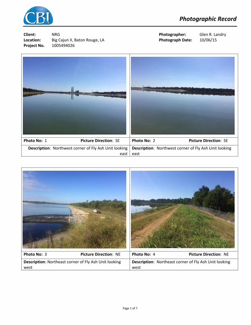
Photographic Record Client: NRG Photographer: Glen R. Landry Location: Big Cajun II, Baton Rouge, LA Photograph Date: 10/06/15 Project No. 1005494026
Photo No: 1 Picture Direction: SE Photo No: 2 Picture Direction: SE
Description: Northwest corner of Fly Ash Unit looking east
Description: Northwest corner of Fly Ash Unit looking east
Photo No: 3 Picture Direction: NE Photo No: 4 Picture Direction: NE
Description: Northeast corner of Fly Ash Unit looking west
Description: Northeast corner of Fly Ash Unit looking west
Page 1 of 7

Photographic Record Client: NRG Photographer: Glen R. Landry Location: Big Cajun II, Baton Rouge, LA Photograph Date: 10/06/15 Project No. 1005494026
Photo No: 5 Picture Direction: W Photo No: 6 Picture Direction: SW
Description: Fly Ash Unit, area of fly ash erosion protection
Description: Animal burrow 30° 43’ 41.9” N, 91° 23’ 21.9” W at toe of slop
Photo No: 7 Picture Direction: SE Photo No: 8 Picture Direction: N
Description: Fly Ash Unit, erosion of fly ash erosion protection areas
Description: Fly Ash Unit, south levee repair near MW-10H; 30° 43’ 17.3” N, 91° 23’ 37.6” W
Page 2 of 7

Photographic Record Client: NRG Photographer: Glen R. Landry Location: Big Cajun II, Baton Rouge, LA Photograph Date: 10/06/15 Project No. 1005494026
Photo No: 9 Picture Direction: SE Photo No: 10 Picture Direction: SE
Description: Fly Ash Unit, 2nd levee repair near MW-10H; 30° 43’ 17.3” N, 91° 23’ 37.6” W
Description: Fly Ash Unit, 2nd levee repair near MW-10H; 30° 43’ 17.3” N, 91° 23’ 37.6” W
Photo No: 11 Picture Direction: NE Photo No: 12 Picture Direction: E
Description: Southwest corner of Fly Ash Unit looking Northeast
Description: Southwest corner of Fly Ash Unit looking Northeast
Page 3 of 7

Photographic Record Client: NRG Photographer: Glen R. Landry Location: Big Cajun II, Baton Rouge, LA Photograph Date: 10/06/15 Project No. 1005494026
Photo No: 13 Picture Direction: W Photo No: 14 Picture Direction: SW
Description: Levee between Fly Ash Unit and Bottom Ash Unit. Looking at stockpiles of bottom ash material within the Fly Ash Unit
Description: Levee between the Bottom Ash Unit and Fly Ash Unit. Bottom Ash Unit on the left, Fly Ash Unit is on the right
Photo No: 15 Picture Direction: E Photo No: 16 Picture Direction: E
Description: Drainage ditch within the Bottom Ash Unit, along north levee
Description: Bottom Ash Unit side slope
Page 4 of 7

Photographic Record Client: NRG Photographer: Glen R. Landry Location: Big Cajun II, Baton Rouge, LA Photograph Date: 10/06/15 Project No. 1005494026
Photo No: 17 Picture Direction: E Photo No: 18 Picture Direction: E
Description: Bottom Ash Unit, Northwest corner of Bottom Ash Unit showing levee repair
Description: Tensar geogrid material used as soil reinforcement to resist the failure plane shear and increased slope stability
Photo No: 19 Picture Direction: S Photo No: 20 Picture Direction: S
Description: Northern levee drainage ditch from the bottom ash
Description: Stockpile of bottom ash in the Bottom Ash Unit (approx. height 20ft)
Page 5 of 7

Photographic Record Client: NRG Photographer: Glen R. Landry Location: Big Cajun II, Baton Rouge, LA Photograph Date: 10/06/15 Project No. 1005494026
Photo No: 21 Picture Direction: E Photo No: 22 Picture Direction:
Description: Bottom ash placement along the inside slope of the northern levee
Description: Small tensile cracking along north Bottom Ash Unit outside slope; 30o 43’ 48.1” N, 91o 23’ 01.5” W
Photo No: 23 Picture Direction: S Photo No: 24 Picture Direction: S
Description: Northeast corner of the Bottom Ash Unit, near underground pipe, geotube in the background barrier protects the outlet pipe from the Bottom Ash Unit
Description: Northeast corner of the Bottom Ash Unit looking South, Treatment Basins on the left and Bottom Ash Unit on right
Page 6 of 7

Photographic Record Client: NRG Photographer: Glen R. Landry Location: Big Cajun II, Baton Rouge, LA Photograph Date: 10/06/15 Project No. 1005494026
Photo No: 25 Picture Direction: N Photo No: 26 Picture Direction: N
Description: Southeast corner of the Bottom Ash Unit discharge slurry discharge point into the Bottom Ash Unit
Description: Southeast corner of the Bottom Ash Unit discharge slurry discharge point into the Bottom Ash Unit
Page 7 of 7