bifurcation analysis versus maximum force criteria in
TRANSCRIPT

Bifurcation analysis versus maximum force criteria informability limit assessment of stretched metal sheetsCitation for published version (APA):Abed-Meraim, F., Peerlings, R. H. J., & Geers, M. G. D. (2014). Bifurcation analysis versus maximum forcecriteria in formability limit assessment of stretched metal sheets. International Journal of Applied Mechanics,6(6), 1450064-1/27. [1450064]. https://doi.org/10.1142/S1758825114500641
DOI:10.1142/S1758825114500641
Document status and date:Published: 01/01/2014
Document Version:Publisher’s PDF, also known as Version of Record (includes final page, issue and volume numbers)
Please check the document version of this publication:
• A submitted manuscript is the version of the article upon submission and before peer-review. There can beimportant differences between the submitted version and the official published version of record. Peopleinterested in the research are advised to contact the author for the final version of the publication, or visit theDOI to the publisher's website.• The final author version and the galley proof are versions of the publication after peer review.• The final published version features the final layout of the paper including the volume, issue and pagenumbers.Link to publication
General rightsCopyright and moral rights for the publications made accessible in the public portal are retained by the authors and/or other copyright ownersand it is a condition of accessing publications that users recognise and abide by the legal requirements associated with these rights.
• Users may download and print one copy of any publication from the public portal for the purpose of private study or research. • You may not further distribute the material or use it for any profit-making activity or commercial gain • You may freely distribute the URL identifying the publication in the public portal.
If the publication is distributed under the terms of Article 25fa of the Dutch Copyright Act, indicated by the “Taverne” license above, pleasefollow below link for the End User Agreement:www.tue.nl/taverne
Take down policyIf you believe that this document breaches copyright please contact us at:[email protected] details and we will investigate your claim.
Download date: 27. Mar. 2022

2nd Reading
November 10, 2014 15:26 WSPC-255-IJAM S1758-8251 1450064
International Journal of Applied MechanicsVol. 6, No. 6 (2014) 1450064 (27 pages)c© Imperial College PressDOI: 10.1142/S1758825114500641
BIFURCATION ANALYSIS VERSUS MAXIMUM FORCECRITERIA IN FORMABILITY LIMIT ASSESSMENT
OF STRETCHED METAL SHEETS
F. ABED-MERAIM∗,‡, R. H. J. PEERLINGS† and M. G. D. GEERS†∗Laboratoire d’Etude des Microstructures et de Mecanique des Materiaux
LEM3, UMR CNRS 7239, Arts et Metiers ParisTech4 rue Augustin Fresnel, 57078 Metz Cedex 3, France
†Department of Mechanical EngineeringEindhoven University of Technology, P.O. Box 513
5600 MB Eindhoven, The Netherlands‡[email protected]
Received 15 June 2013Revised 4 September 2014Accepted 4 September 2014Published 12 November 2014
The present contribution deals with the prediction of diffuse necking in the context offorming and stretching of metal sheets. For this purpose, two approaches are investigated,namely bifurcation and the maximum force principle, with a systematic comparison oftheir respective ability to predict necking. While the bifurcation approach is of quitegeneral applicability, some restrictions are shown for the application of maximum forceconditions. Although the predictions of the two approaches are identical for particularloading paths and constitutive models, they are generally different, which is even the casefor elasticity, confirming the distinct nature of the two concepts. Closed-form expressionsof the critical stress and strain states are derived for both criteria in elasto-plasticity andrigid-plasticity for a variety of hardening models. The resulting useful formulas in rigid-plasticity are shown to also accurately represent the elasto-plastic critical states for smallratios of the hardening modulus with respect to Young’s modulus. Finally, the well-knownexpression of Swift’s diffuse necking criterion, whose foundations are attributed in theliterature to the maximum force principle, is shown here to originate from the bifurcationapproach instead, providing a sound justification for it.
Keywords: Bifurcation; maximum force principle; forming limits; diffuse and localizednecking; stretched metal sheets; formability.
1. Introduction
In the literature dealing with plastic instabilities, and the analysis of sheet metalforming processes, quite a large number of forming limit criteria have been devel-oped. However, a comprehensive and rigorous comparison of their theoretical foun-dations and underlying assumptions is seldom made. Listing all these criteria proves
‡Corresponding author.
1450064-1

2nd Reading
November 10, 2014 15:26 WSPC-255-IJAM S1758-8251 1450064
F. Abed-Meraim, R. H. J. Peerlings & M. G. D. Geers
to be difficult, considering the multitude of variants derived from some of theseapproaches. A short review reveals, however, that those criteria could be classi-fied into distinct categories, depending on their fundamental basis as well as theirtheoretical or physical background.
For stretched metal sheets, two forms of necking may occur, namely diffuseand localized necking. It has been shown that diffuse necking appears prior tolocalized necking, and it is now well recognized that the maximum allowable strainin sheet metal forming is restricted by localized necking. For this reason, most ofthe theoretical Forming Limit Diagrams (FLDs) are now based on the onset oflocalization. From an experimental viewpoint, the FLDs are obtained at localizednecking for different loading paths (uniaxial tensile (UT) test, biaxial tensile tests,plane-strain tensile (PT) test) using Marciniak’s or Nakazima’s test with specimensof different widths. Note that this FLD concept was first introduced by Keeler[1965] and Goodwin [1968] in order to determine the critical strains that could leadto defective parts.
Early instability criteria were based on the maximum force principle, originatingfrom Considere [1885] and its two-dimensional (2D) extension by Swift [1952] forapplication to metal sheets. These criteria, in their original form, were known topredict diffuse necking. Later, these maximum-force-based criteria were extendedby Hora et al. [1996] and subsequently by Mattiasson et al. [2006] in order to pre-dict localized necking, and enhanced versions were developed to take into accountthickness effects, strain-path changes, etc. Note also that Hill’s zero-extension crite-rion [Hill, 1952], predicting localized necking on the left-hand side of the FLD, wasdeveloped almost in the same period as Swift’s diffuse necking criterion.
Another approach, postulating a pre-existing defect in the material sheet, wasproposed by Marciniak and Kuczynski [1967]. In its original version, the Marciniak–Kuczynski (M–K) model can be regarded, in a sense, as a complementary approachto Hill’s zero-extension criterion, since no zero-extension direction exists for positivebiaxial stretching. However, since localized necking in biaxial stretching is observedin practice, a geometric imperfection has to be introduced in the M–K model tocapture this phenomenon, which may provide some justification to this imperfectiontheory. This model was subsequently extended by Hutchinson and Neale [1978] tothe prediction of the left-hand side of the FLD by allowing the imperfection bandto rotate until a localized neck is detected.
Drucker’s and Hill’s theory of loss of material stability [Drucker, 1956; Hill,1958], also referred to as the general bifurcation criterion, represents another classof approaches for necking prediction. Belonging to the same class, limit-point bifur-cation appeared later [Valanis, 1989], and it has been shown that for associativeelasto-plasticity, limit-point bifurcation coincides with general bifurcation. For local-ized necking, Rudnicki and Rice established a bifurcation criterion based on loss ofellipticity (i.e., singularity of the acoustic tensor), also known as the discontinuousbifurcation criterion [Rudnicki and Rice, 1975; Rice, 1976]. In the same way, some
1450064-2

2nd Reading
November 10, 2014 15:26 WSPC-255-IJAM S1758-8251 1450064
Bifurcation Analysis versus Maximum Force Criteria in Formability Limit
authors suggested the use of loss of strong ellipticity [Bigoni and Hueckel, 1991;Neilsen and Schreyer, 1993], which was shown to coincide with Rice’s criterion forassociative elasto-plastic models.
A final significant class of criteria concerns those based on stability theory.Within this approach, necking and localization phenomena are tackled by stabilityanalysis of the local equilibrium equations. The starting point is the mathemati-cal concept of stability, introduced by Lyapunov [1892] and commonly applied tostructural instability problems [see, e.g., Abed-Meraim, 1999; Mojahedi et al., 2013].The associated technique of linear perturbation was extended to material instabilityproblems by Molinari and Clifton [1987]. To investigate the rate of growth of theperturbation, its governing equations are linearized, and the resulting eigenvalueproblem will characterize stable and unstable modes. For strain-rate dependentmaterial models, this approach could be regarded as an interesting alternative tobifurcation theory; the latter is known not to apply for strain-rate sensitive materi-als. In the limit of vanishing viscous effects, this methodology was shown to recoverRice’s bifurcation criterion [Barbier et al., 1998; Benallal, 2008].
From the above overview of the various approaches for necking and localizationprediction, an interesting observation can be made. Indeed, while the M–K analysisand Maximum Force Criteria (MFC) have been widely used in the literature, fewapplications of Rice’s strain localization theory to sheet metal formability have beenpublished, and they are mostly restricted to plane-stress assumptions and simpleconstitutive models [see, e.g., Doghri and Billardon, 1995]. Recently, Rice’s bifur-cation criterion has been used to investigate formability limits of metallic materials(see, Haddag et al. [2009] and Mansouri et al. [2014] using phenomenological consti-tutive modeling and Franz et al. [2009] using micromechanical approaches). Besidesits sound theoretical basis, this bifurcation criterion has also been shown to pro-vide a useful tool to investigate the impact of microstructural mechanisms on theformability limit of multiphase polycrystalline materials [Franz et al., 2011; 2013].
In the present contribution, attention is restricted to diffuse necking predictionsapplied to the in-plane stretching of metal sheets. Although the investigation of dif-fuse necking, as an approach to formability limits, may be seen as conservative whencompared to localized necking predictions, there is yet a need for the former analysis.Besides its evident academic interest, explicit expressions for the critical hardeningmoduli allow loading paths, which are less favorable to necking, to be selected, andcan therefore be used in experiments specifically designed for the material parameteridentification relying on mechanical tests with homogeneous deformation. To thisend, two approaches are thoroughly investigated, i.e., the maximum force principleand the bifurcation approach. Their respective ability to predict this type of geo-metric instability phenomena are systematically compared for different constitutivemodels.
The paper is outlined as follows. In Sec. 2, the problem statement is given alongwith the basic equations that govern the bifurcation analysis and the maximum
1450064-3

2nd Reading
November 10, 2014 15:26 WSPC-255-IJAM S1758-8251 1450064
F. Abed-Meraim, R. H. J. Peerlings & M. G. D. Geers
force principle. Some restrictions regarding the range of validity of the MFC arealso pointed out and discussed. Section 3 is a preliminary illustrative study withinthe framework of elasticity, where the predictions of the two approaches are shownto differ significantly, which confirms that they are based on distinct concepts. InSec. 4, the critical stress and strain states are derived within the framework ofelasto-plasticity for both criteria as closed-form expressions valid for a variety ofhardening models. The analysis is then specialized in Sec. 5 for rigid-plasticity,where the resulting formulas are shown to accurately represent the elasto-plasticcritical states for small ratios of the hardening modulus with respect to Young’smodulus. Finally, some concluding remarks are given in Sec. 6. For completenessand practical applications, the critical hardening moduli and the associated criticalstrains are provided in Appendix A for a set of popular hardening laws.
2. Equilibrium Equations and Problem Statement
In this section, the problem statement and some general considerations will begiven. Because some equations and principles are of quite general validity and com-mon to all of the remaining sections of the paper, it has been chosen to summarizethem in the current section for conciseness. These include the equilibrium equa-tions, which are independent of the selected constitutive equations, the governingequations underlying the bifurcation analysis, and those related to the maximumforce principle.
2.1. Quasi-static equilibrium equations
Let us consider a metal sheet as sketched in Fig. 1, which is subjected to biaxialloading conditions. The problem geometry is defined by its current parameters l1, l2,l3 and their initial values L1, L2, L3, which denote the dimensions along the majorstrain direction, the minor strain direction and the thickness direction, respectively.
The sheet is stretched by applying a biaxial loading state (F1(λ), F2(λ)), in whichλ(t) is a monotonously increasing function acting as a load control parameter. Theprincipal logarithmic strains, which remain parallel to the loading directions (1, 2)
1F
1F
F2
F2
1ee
2ee
3e l
2l1
l3
Fig. 1. Illustration of a metal sheet subjected to in-plane biaxial loading.
1450064-4

2nd Reading
November 10, 2014 15:26 WSPC-255-IJAM S1758-8251 1450064
Bifurcation Analysis versus Maximum Force Criteria in Formability Limit
(i.e., only isotropic material models are considered in this work), are given by
εi = ln(
liLi
), i = 1, 2, 3. (1)
Using the principal Cauchy stress components (σ1, σ2), the quasi-static equilibriumequations read {
F1 = σ1l2l3
F2 = σ2l1l3(2)
which, combined with Eq. (1), can be rewritten as
F1
L2L3= σ1e
(ε2+ε3)
F2
L1L3= σ2e
(ε1+ε3).
(3)
For bifurcation analysis or application of MFC, the rate form of the equilibriumequations is usually more convenient, which reads
F1
l2l3= σ1 + σ1(ε2 + ε3)
F2
l1l3= σ2 + σ2(ε1 + ε3).
(4)
Note that so far, no constitutive equations had to be specified, since the aboveequilibrium equations do not depend on any material behavior law. However, theseequations are often simplified, e.g., whenever the volume change can be neglected;this will be discussed at the end of this section.
2.2. General bifurcation analysis
The application of a biaxial loading state (F1(λ), F2(λ)), which is characterized bythe loading control parameter λ(t), results in a quasi-static response indicated bysuperscript 0. This response (ε0
i (λ), σ0i (λ)), referred to as the fundamental equi-
librium path, may exhibit bifurcation when the loading reaches a critical value.Theoretically, this means that the equilibrium equations may lose uniqueness forsome critical values of the loading. The bifurcated solution, which intersects the fun-damental equilibrium path, is characterized by the critical load and the associatedbifurcation mode. This type of instability phenomenon has been widely investi-gated in elasticity [see, e.g., Koiter, 1945; Timoshenko and Gere, 1961; Budiansky,1974] as well as in plasticity [see, Hill, 1958; Hutchinson, 1974; Abed-Meraim andNguyen, 2007]. For practical applications, the analysis of such buckling instabilitiesamounts to solving an eigenvalue problem, in which one seeks the first eigenvalue,corresponding to the lowest critical load, and the associated eigenmode [see, e.g.,Liu et al., 2011; Gulshan Taj and Chakrabarti, 2013; Toh et al., 2013].
1450064-5

2nd Reading
November 10, 2014 15:26 WSPC-255-IJAM S1758-8251 1450064
F. Abed-Meraim, R. H. J. Peerlings & M. G. D. Geers
The bifurcation equations are classically obtained by first assuming that thereexist two different solutions for the rate equilibrium equations (i.e., the fundamentalpath and the bifurcated solution). Then, the corresponding governing equations (i.e.,the rate equilibrium equations associated with these two solutions) are subtractedfrom each other when evaluated at the first bifurcation point. At this bifurcationpoint, where the two solutions intersect, there may be only loss of uniqueness forsome rate variables; the non-incremental quantities themselves are equal at thispoint of onset of bifurcation. Applying this procedure to Eq. (4), which representsthe rate equilibrium equations for the above sheet under stretching, the bifurcationequations are derived as follows:{
∆σ1 + σ01(∆ε2 + ∆ε3) = 0
∆σ2 + σ02(∆ε1 + ∆ε3) = 0,
(5)
where ∆A = A − A0 denotes the difference between any rate variable A evaluatedon the bifurcated path and on the fundamental equilibrium path, respectively.
To proceed further with the bifurcation analysis (5), the constitutive equationsare required, so that the corresponding eigenvalue problem is completely definedand can therefore be solved. This will be done in the subsequent sections, in whichthe superscript 0 will be omitted for clarity.
2.3. Maximum force principle
This classical approach was coined by Considere [1885] who observed that neck-ing occurs in a rounded bar under uniaxial tension when the applied load reachesa maximum. This earlier one-dimensional (1D) necking criterion has subsequentlybeen extended to biaxial loading conditions [see Swift, 1952]. Note that both theConsidere and Swift’52 criteria are known to predict diffuse necking, which generallyoccurs prior to localized necking in the context of sheet metal forming. For the pre-diction of localized necking, Hill [1952] proposed a criterion based on the formationof a band of stationary extension, while Hora et al. [1996] extended Considere’s cri-terion by taking into account the strain-path evolution after diffuse necking towardsa PT state. It is worth noting that this class of criteria, referred to as the MFC, isnoticeably popular in the literature and has been widely applied to determine FLDsat diffuse or localized necking.
In this section, attention is restricted to diffuse necking predictions by reconsid-ering the basic equations on which the Considere and Swift’52 criteria are based. Forthe above-described sheet under stretching, the condition of maximum load alongthe major strain direction is given by
σ1 + σ1(ε2 + ε3) = 0 (6)
while the maximum force condition for the load parallel to the minor straindirection is
σ2 + σ2(ε1 + ε3) = 0. (7)
1450064-6

2nd Reading
November 10, 2014 15:26 WSPC-255-IJAM S1758-8251 1450064
Bifurcation Analysis versus Maximum Force Criteria in Formability Limit
In the context of plasticity, the MFC have been mainly developed under the assump-tions of incompressibility and a plane-stress state, which are well-justified withinthe biaxial loading conditions and large plastic deformations to which metal sheetsare subjected. For instance, under these conditions, Eq. (6) leads to the well-known1D expression of Considere’s criterion (i.e., σ1/ε1 = dσ1/dε1 = σ1), which expressesthat necking starts when the uniaxial hardening modulus h = dσ1/dε1 drops to thevalue of the stress.
For biaxial loading, the extension by Swift [1952] suggests the application of theMFC at a simultaneous maximum of the forces. However, the simultaneous occur-rence of maximum forces is only possible for some trivial loading paths. This hasbeen demonstrated through experiments [see, e.g., Habbad, 1994], but can also beshown by further analyzing Eqs. (6) and (7). For the prediction of FLDs, a propor-tional loading is usually adopted, characterized by a constant parameter β = ε2/ε1
that defines the loading path. This also results in a linear relationship between thein-plane principal stress components (i.e., σ2/σ1 = α). In this case, it is straight-forward from Eqs. (6) and (7) that a simultaneous maximum of the forces is onlypossible for α = 0 or β = 1. The first case, α = 0, corresponds to the UT test,and the second, β = 1, to equibiaxial expansion (EBE). Note that for both cases,the simultaneous maximum amounts to the condition of a maximum of the forcealong the major strain direction. Indeed, in UT the second condition (Eq. (7)) isobviously always satisfied, since F2 = 0 ⇒ σ2 = 0. For EBE, the symmetry of theproblem reveals that condition (7) simply reduces to condition (6).
To summarize, it has been shown that the condition of a simultaneous maximumof the forces (Eqs. (6) and (7)) only occurs for two particular loading paths, whereasthe condition of maximum force along the major strain direction (Eq. (6)) may bepossible for the whole range of loading paths that make up an FLD, and couldtherefore represent an alternative criterion. On the other hand, the condition ofmaximum force along the minor strain direction (Eq. (7)) is shown not to hold forsome loading paths; therefore, this latter condition will no longer be investigated inthe subsequent sections.
2.4. Incompressibility
In what follows, for the sake of simplicity, the assumption of incompressibility willbe adopted. This assumption is justified by three main motivations:
• In the framework of elasticity, which represents the preliminary study of Sec. 3,our main objective is to clarify some general aspects, and especially to emphasizethat the bifurcation and maximum force principle are two distinct concepts.
• In elasto-plasticity, the deformation levels corresponding to the investigated phe-nomena (bifurcation, necking, etc.) are sufficiently large to justify neglectingthe elastic strain, or at least its compressible part, as compared to the plasticstrain.
1450064-7

2nd Reading
November 10, 2014 15:26 WSPC-255-IJAM S1758-8251 1450064
F. Abed-Meraim, R. H. J. Peerlings & M. G. D. Geers
• It will allow a consistent comparison with results provided in the literature forthe MFC, which are mostly available as closed-form expressions derived underthe incompressibility assumption (i.e., rigid-plasticity).
Making use of volume conservation, the equilibrium Eq. (3) simplify to
F1
L2L3= σ1e
−ε1
F2
L1L3= σ2e
−ε2
(8)
with their rate form given by:
F1
l2l3= σ1 − σ1ε1
F2
l1l3= σ2 − σ2ε2.
(9)
With these simplified equilibrium equations, the preceding equations that governbifurcation and maximum force conditions, Eq. (5) and Eqs. (6) and (7), respec-tively, can be easily modified accordingly.
3. Preliminary Study in Elasticity
The aim of this section is to illustrate the above-discussed concepts of bifurcationand maximum force principle in the simple case of linear elasticity. This preliminarystudy, allowing analytical solutions and closed-form expressions of the critical loads,constitutes a useful stepping stone towards more realistic constitutive models.
3.1. Elastic fundamental equilibrium path
Let us consider again the sheet under biaxial stretching shown in Fig. 1. The asso-ciated strain and stress tensors ε and σ are given by their corresponding matricesε and σ with respect to the Cartesian basis considered as
ε =
ε1 0 00 ε2 00 0 −(ε1 + ε2)
, σ =
σ1 0 00 σ2 00 0 0
. (10)
The governing constitutive equations for linear incompressible elasticity are givenin tensorial form by
ε =3
2Eσ − 1
2Etr(σ)I2, (11)
where E is the Young’s modulus, tr( ) stands for the trace operator, and I2 denotesthe second-order identity tensor. These constitutive equations can be rewritten in
1450064-8

2nd Reading
November 10, 2014 15:26 WSPC-255-IJAM S1758-8251 1450064
Bifurcation Analysis versus Maximum Force Criteria in Formability Limit
component form as
ε1 =1
2E(2σ1 − σ2)
ε2 =1
2E(2σ2 − σ1)
(12)
or alternatively in terms of stress components:
σ1 =2E
3(2ε1 + ε2)
σ2 =2E
3(2ε2 + ε1).
(13)
By setting β = ε2/ε1, a constant parameter that characterizes the loading path(β ∈ [−1/2, 1], e.g., β = −1/2 for UT, β = 0 for PT, β = 1 for EBE), it can beshown that if σ2/σ1 = α, the following relationship between β and α holds:
β =2α − 12 − α
⇔ α =1 + 2β
2 + β. (14)
Combining the above equations, the fundamental equilibrium solution can beobtained as follows:
ε0(λ) = λ(t)
1 0 0
0 β 00 0 −(1 + β)
, σ0(λ) =
2E
3(2 + β)λ(t)
1 0 0
0 α 00 0 0
, (15)
where λ = ε1 is a loading control parameter. In fact, Eq. (15) represents a one-parameter family of fundamental paths, and for each value of parameter α or β
corresponding to a particular loading path, we can investigate the bifurcation orMFC.
3.2. Bifurcation analysis
The bifurcation Eq. (5), taking into account the incompressibility condition,ε1 + ε2 + ε3 = 0, reduces to the following two equations ∆σ1 − σ1∆ε1 = 0 and∆σ2 − σ2∆ε2 = 0. The latter, combined with the elastic constitutive Eq. (13),written in their rate form, lead to the following two-equation system:
K
[∆ε1
∆ε2
]= 0, with K =
4E
3− σ1
2E
3
2E
34E
3− σ2
. (16)
The above linear algebraic system results in an eigenvalue problem, in which thebifurcation condition necessarily involves the singularity of matrix K, leading to
detK = αX2 − 4E
3(1 + α)X + 3
(2E
3
)2
= 0 (17)
1450064-9

2nd Reading
November 10, 2014 15:26 WSPC-255-IJAM S1758-8251 1450064
F. Abed-Meraim, R. H. J. Peerlings & M. G. D. Geers
with X = σ1 and σ2 = ασ1. The above second-order polynomial equation has tworeal roots that are closed-form expressions of the elastic properties (i.e., here theYoung modulus) and the loading path parameter (α or β). As usual in bifurcationanalysis, we restrict attention to the lowest critical load, which corresponds to thefollowing critical state in terms of stress and strain:
σc1 =
2E
3α[(1 + α) −
√α2 − α + 1]
σc2 =
2E
3[(1 + α) −
√α2 − α + 1]
,
εc1 =
(2 − α)3α
[(1 + α) −√
α2 − α + 1]
εc2 =
(2α − 1)3α
[(1 + α) −√
α2 − α + 1].
(18)
With these expressions, we can obtain the critical state for the whole range ofloading paths of interest; Table 1 reports the critical stresses and strains for threetypical loading paths corresponding to uniaxial tension (UT) (α = 0 or β = −1/2),plane-strain tension (PT) (α = 1/2 or β = 0), and EBE (α = 1 or β = 1).
3.3. Maximum force conditions
For the reasons discussed previously, focus is confined to the maximum force con-dition along the major strain direction. Therefore, Eq. (6) along with the incom-pressibility condition leads to
σ1 − σ1ε1 = 0. (19)
Using the constitutive Eq. (13) and the condition of proportional loading ε2 = βε1,we obtain the critical state in terms of stress and strain:
σc
1 =2E
3(2 + β)
σc2 =
2E
3(1 + 2β)
,
{εc1 = 1
εc2 = β.
(20)
Again, the whole range of loading paths can be investigated with the expressionsabove; for comparison purposes, we specify in Table 2 the corresponding criticalloads for the same particular loading paths as for the bifurcation analysis.
Table 1. Critical elastic bifurcation states for three typical loading paths.
Loading path
UT PT EBE
Critical state β = −1/2 β = 0 β = 1
σc1 E 2E(1 − 1/
√3) 2E/3
σc2 0 E(1 − 1/
√3) 2E/3
εc1 1
√3(√
3 − 1)/2 1/3
εc2 −1/2 0 1/3
1450064-10

2nd Reading
November 10, 2014 15:26 WSPC-255-IJAM S1758-8251 1450064
Bifurcation Analysis versus Maximum Force Criteria in Formability Limit
Table 2. Critical elastic states associated with the MFC for threetypical loading paths.
Loading path
UT PT EBE
Critical state β = −1/2 β = 0 β = 1
σc1 E 4E/3 2E
σc2 0 2E/3 2E
εc1 1 1 1
εc2 −1/2 0 1
3.4. Discussion
As shown previously, the condition of simultaneous maximum of the forces is onlypossible for two typical loading paths (i.e., UT and EBE). For these two loadingpaths, this condition also amounts to that of the maximum force along the majorstrain direction, as reported in Table 2.
The results yielded by the bifurcation analysis and MFC can be comparedthrough their respective equations (i.e., Eqs. (18) and (20)) as well as throughTables 1 and 2. For a wide range of loading paths corresponding to β ∈ [−1/2, 1],Fig. 2 compares the bifurcation and MFC results in terms of both critical strainsand the associated critical stresses. Although less commonly used, the stress repre-sentation of critical states is also shown here for subsequent comparison with theelasto-plastic case.
One can observe that except for the case of UT, the results given by the bifurca-tion analysis (solid lines) differ significantly from those given by the MFC (dashedlines). The critical loads predicted by bifurcation are typically lower than those ofthe MFC. Thus, as expected, this simple illustrative problem confirms that these
1ε
2ε
1 / 2β = − 0β = 1β =
0
0.2
0.4
0.6
0.8
1
1.2
-0.6 -0.4 -0.2 0 0.2 0.4 0.6 0.8 1 1.2
MFC
Bifurca on
Minor strain
Maj
orst
rain
0
0.5
1
1.5
2
2.5
0 0.5 1 1.5 2 2.5
MFC
Bifurca on
Minor stress (normalized)
Maj
orst
ress
(nor
mal
ized)
1 Eσ
2 Eσ
0α = 1/ 2α = 1α =
Fig. 2. Comparison of elastic critical strains/stresses given by bifurcation and MFC.
1450064-11

2nd Reading
November 10, 2014 15:26 WSPC-255-IJAM S1758-8251 1450064
F. Abed-Meraim, R. H. J. Peerlings & M. G. D. Geers
two approaches represent intrinsically distinct concepts. Indeed, while bifurcationis associated with loss of uniqueness, it seems more difficult to provide theoreticalfoundations (e.g., stability, loss of uniqueness) for the MFC concept.
Note that the validity of these observations is not limited to the case of incom-pressibility; the same analyses without volume conservation restrictions have beencarried out and show similar differences between the two approaches.
Note also that even though the bifurcation analysis results coincide with thoseof MFC for UT, this does not imply that for this particular loading path the twoconcepts are equivalent. In elasticity and conventional elasto-plasticity, bifurcationand MFC yield the same critical loads for UT, but this is not necessarily the casefor other constitutive models (e.g., elasto-viscoplasticity).
4. Investigation in Elasto-Plasticity
In this section, the two approaches (i.e., bifurcation and MFC) previously investi-gated in elasticity will be further explored for a more realistic material model, com-monly used in sheet metal forming applications. The same assumptions as beforeare made along with the same notations and definitions.
4.1. Elasto-plastic fundamental equilibrium path
We consider in what follows a general form of elasto-plastic constitutive equationswith incompressible elasticity and isotropic hardening. This constitutive framework,despite its simplicity, can include a large variety of work hardening models as typ-ically used in sheet metal forming. Using the additive decomposition of the strainrate tensor into its elastic and plastic parts εe and εp, respectively, the elasticitylaw reads
εe = ε − εp =3
2Eσ − 1
2Etr(σ)I2. (21)
The plastic strain rate tensor is given by the usual associative flow rule:
εp = p∂F
∂σ, (22)
where p denotes the plastic multiplier and F the yield surface, here given by
F = σeq − Y (ε p) (23)
in which σeq =√
3/2σ′ : σ′ is the von Mises equivalent stress, function of thedeviatoric stress tensor σ′. Y is the yield stress describing isotropic hardening,which is a function of the equivalent plastic strain ε p, with ˙ε p =
√2/3εp : εp.
Making use of the consistency condition, the plastic multiplier can be determinedalong with the elasto-plastic tangent modulus in the following particular tensorialform:
32E
σ − 12E
tr(σ)I2 = ε − 32
E
(E + h)1
σ2eq
(σ′ ⊗ σ′) : ε (24)
1450064-12

2nd Reading
November 10, 2014 15:26 WSPC-255-IJAM S1758-8251 1450064
Bifurcation Analysis versus Maximum Force Criteria in Formability Limit
in which h = dY /dε p is the scalar hardening modulus. In terms of components wehave
σ1 =
2E
3(2ε1 + ε2) − E
(E + h)E
σ2eq
σ1(σ1ε1 + σ2ε2)
σ2 =2E
3(2ε2 + ε1) − E
(E + h)E
σ2eq
σ2(σ1ε1 + σ2ε2).
(25)
The material response consists of two stages; an elastic stage followed by an elasto-plastic regime. Note that the elastic case investigated in the previous section can berecovered in the limit of h → +∞ in Eqs. (24) or (25), whereby the uniaxial tangentmodulus ET = Eh/(E + h) consistently tends toward the Young modulus E. In thesame way as before, it can be shown that a proportional loading in terms of straincomponents with parameter β results in proportional stress components with ratioα, with the same relation (14) between α and β. Making use of these proportionalityfactors, the constitutive Eq. (25) can be rewritten in a more compact form:
σ1 =2ET
3(2 + β)ε1
σ2 =2ET
3(1 + 2β)ε1.
(26)
For a biaxial loading controlled by an increasing parameter λ(t), the fundamentalsolution in terms of strain ε0(λ) given by Eq. (15) still holds. In terms of stress,however, the expression given by Eq. (15) only holds for the elastic stage of theloading (i.e., for λ(t) ∈ [0, λY ], with λY =
√3σy/[2E
√β2 + β + 1], and σy the
initial yield stress). For the plastic range (i.e., λ(t) > λY ), the fundamental responsein terms of stress is given by
σ01 = σY
1 +23(2 + β)
∫ λ(t)
λY
ET dλ
σ02 = σY
2 +23(1 + 2β)
∫ λ(t)
λY
ET dλ,
(27)
where σY1 = σy/
√α2 − α + 1 and σY
2 = ασY1 .
For a linear hardening model, for which h and hence ET are constant, a closed-form solution can be obtained in straightforward manner. In the general case ofnonlinear hardening models, the following convenient relationship can be derived:
Eε p + Y (ε p) =2E√
β2 + β + 1√3
ε1. (28)
1450064-13
2nd Reading
November 10, 2014 15:26 WSPC-255-IJAM S1758-8251 1450064
F. Abed-Meraim, R. H. J. Peerlings & M. G. D. Geers
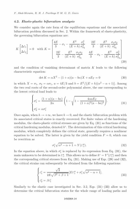
4.2. Elasto-plastic bifurcation analysis
We consider again the rate form of the equilibrium equations and the associatedbifurcation problem discussed in Sec. 2. Within the framework of elasto-plasticity,the governing bifurcation equations are:
K
[∆ε1
∆ε2
]= 0 with K =
4E
3− σ1 − E2
(E + h)σ2
1
σ2eq
2E
3− E2
(E + h)σ1σ2
σ2eq
2E
3− E2
(E + h)σ1σ2
σ2eq
4E
3− σ2 − E2
(E + h)σ2
2
σ2eq
(29)
and the condition of vanishing determinant of matrix K leads to the followingcharacteristic equation:
detK = αX2 − (1 + α)(a − bα)X + aET = 0 (30)
in which X = σ1, σ2 = ασ1, a = 4E/3 and b = E2/[(E + h)(α2 − α + 1)]. Amongthe two real roots of the second-order polynomial above, the one corresponding tothe lowest critical load leads to
σc
1 =(1 + α)(a − bα)
2α
(1 −
√1 − 4αaET
(1 + α)2(a − bα)2
).
σc2 = ασc
1
(31)
Once again, when h → +∞, we have b → 0, and the elastic bifurcation problem withits associated critical states is exactly recovered. For finite values of the hardeningmodulus, the elasto-plastic critical stresses are given by Eq. (31) as functions of thecritical hardening modulus, denoted hc. The determination of this critical hardeningmodulus, which completely defines the critical state, generally requires a nonlinearequation to be solved. The latter is given by the yield condition F = 0, which canbe rewritten as
σc1
√α2 − α + 1 = Y (ε p
c). (32)
In the equation above, in which σc1 is replaced by its expression from Eq. (31), the
main unknown to be determined is ε pc . This allows us to define hc = Y ′(ε p
c) and thenthe corresponding critical stresses from Eq. (31). Making use of Eqs. (28) and (32),the critical strains can subsequently be obtained from the following equations:
εc1 =
√3
2E√
β2 + β + 1[Eε p
c + σc1
√α2 − α + 1].
εc2 = βεc
1
(33)
Similarly to the elastic case investigated in Sec. 3.2, Eqs. (31)–(33) allow us todetermine the critical bifurcation states for the whole range of loading paths and
1450064-14

2nd Reading
November 10, 2014 15:26 WSPC-255-IJAM S1758-8251 1450064
Bifurcation Analysis versus Maximum Force Criteria in Formability Limit
Table 3. Critical elasto-plastic bifurcation states for three typical loading paths.
Loading path
UT PT EBE
Critical state β = −1/2 β = 0 β = 1
σc1 Ec
T E + EcT −
qE2 − (2/3)EEc
T + Ec2T 1/3(E + 3Ec
T ) − 1/3|E − 3EcT |
σc2 0 σc
1/2 σc1
εc1 εp
c + EcT /E
√3/2(εp
c +√
3σc1/2E) 1/2(εp
c + σc1/E)
εc2 −εc
1/2 0 εc1
for a variety of nonlinear hardening laws. To illustrate this, Table 3 reports thecritical stress and strain states for three typical loading paths.
In Table 3, the results depend on EcT = Ehc/Ehc(E + hc) and thus on the
critical hardening modulus hc, which itself depends on ε pc . This critical equivalent
plastic strain is determined by solving Eq. (32), which represents a linear or non-linear algebraic equation depending on the isotropic hardening law selected. Forillustration, the resulting critical equivalent plastic strain and hardening modulus,when h/E � 1, are given in Appendix A for a set of common isotropic hardeningmodels.
Based on the results in Table 3, two observations are interesting to make. Thefirst is that when h/E � 1, the critical stress for the PT loading path is equivalentto the value of σc
1 = 4EcT /3. The second is that in EBE, there is a threshold value
for the hardening (i.e., hL = E/2) under which the critical stress is σc1 = 2Ec
T , andbeyond which it is equal to σc
1 = 2E/3, regardless of plasticity. For hardening modulibeyond this threshold, the critical stresses for EBE found in elasticity (see Sec. 3,Table 1) are recovered; however, the associated critical strains are still affected byplasticity.
4.3. MFC
The discussions in Secs. 2 and 3 regarding the range of applicability of the MFCstill hold in the context of elasto-plasticity. The maximum force condition along themajor strain direction, given by Eq. (19), together with the constitutive Eq. (26)leads to
σc
1 =2Ec
T
3(2 + β)
σc2 =
2EcT
3(1 + 2β).
(34)
Note that the resulting elasto-plastic critical stresses are given by expressions thatare nearly identical to those obtained in the elastic case (see Eq. (20)), wherebyYoung’s modulus E is replaced by the elasto-plastic scalar tangent modulus Ec
T .
1450064-15
2nd Reading
November 10, 2014 15:26 WSPC-255-IJAM S1758-8251 1450064
F. Abed-Meraim, R. H. J. Peerlings & M. G. D. Geers
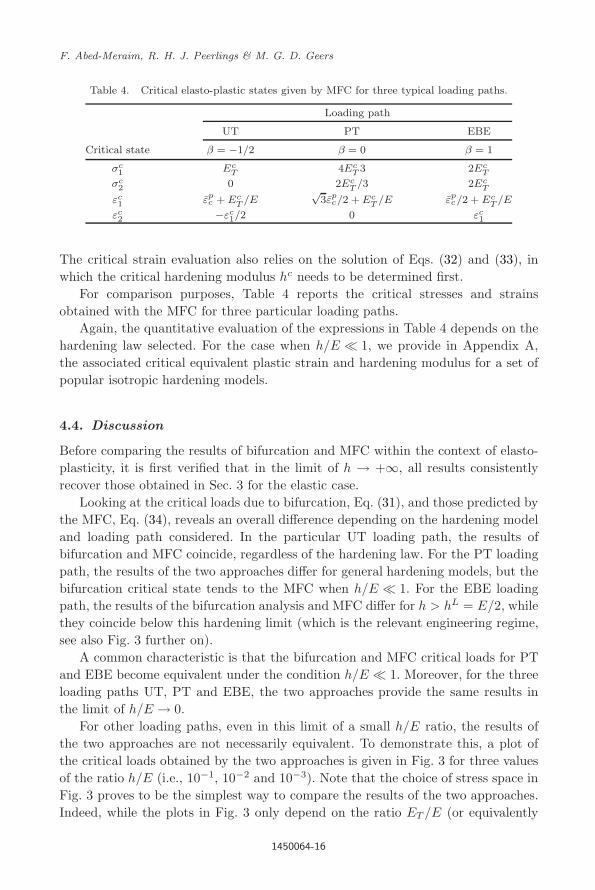
Table 4. Critical elasto-plastic states given by MFC for three typical loading paths.
Loading path
UT PT EBE
Critical state β = −1/2 β = 0 β = 1
σc1 Ec
T 4EcT 3 2Ec
T
σc2 0 2Ec
T /3 2EcT
εc1 εp
c + EcT /E
√3εp
c/2 + EcT /E εp
c/2 + EcT /E
εc2 −εc
1/2 0 εc1
The critical strain evaluation also relies on the solution of Eqs. (32) and (33), inwhich the critical hardening modulus hc needs to be determined first.
For comparison purposes, Table 4 reports the critical stresses and strainsobtained with the MFC for three particular loading paths.
Again, the quantitative evaluation of the expressions in Table 4 depends on thehardening law selected. For the case when h/E � 1, we provide in Appendix A,the associated critical equivalent plastic strain and hardening modulus for a set ofpopular isotropic hardening models.
4.4. Discussion
Before comparing the results of bifurcation and MFC within the context of elasto-plasticity, it is first verified that in the limit of h → +∞, all results consistentlyrecover those obtained in Sec. 3 for the elastic case.
Looking at the critical loads due to bifurcation, Eq. (31), and those predicted bythe MFC, Eq. (34), reveals an overall difference depending on the hardening modeland loading path considered. In the particular UT loading path, the results ofbifurcation and MFC coincide, regardless of the hardening law. For the PT loadingpath, the results of the two approaches differ for general hardening models, but thebifurcation critical state tends to the MFC when h/E � 1. For the EBE loadingpath, the results of the bifurcation analysis and MFC differ for h > hL = E/2, whilethey coincide below this hardening limit (which is the relevant engineering regime,see also Fig. 3 further on).
A common characteristic is that the bifurcation and MFC critical loads for PTand EBE become equivalent under the condition h/E � 1. Moreover, for the threeloading paths UT, PT and EBE, the two approaches provide the same results inthe limit of h/E → 0.
For other loading paths, even in this limit of a small h/E ratio, the results ofthe two approaches are not necessarily equivalent. To demonstrate this, a plot ofthe critical loads obtained by the two approaches is given in Fig. 3 for three valuesof the ratio h/E (i.e., 10−1, 10−2 and 10−3). Note that the choice of stress space inFig. 3 proves to be the simplest way to compare the results of the two approaches.Indeed, while the plots in Fig. 3 only depend on the ratio ET /E (or equivalently
1450064-16

2nd Reading
November 10, 2014 15:26 WSPC-255-IJAM S1758-8251 1450064
Bifurcation Analysis versus Maximum Force Criteria in Formability Limit
0
0.5
1
1.5
2
2.5
0 0.5 1 1.5 2 2.5
MFC
Bifurca on h/E=0.1
Bifurca on h/E=0.01
Bifurca on h/E=0.001
Maj
or st
ress
(nor
mal
ized)
Minor stress (normalized)
1 TEσ
2 TEσ
1α =1/ 2α =0α =
Fig. 3. Comparison between the bifurcation and MFC results for three values of h/E.
on the h/E ratio), the alternative representation in terms of critical strains wouldrequire the determination of the critical equivalent plastic strain (Eq. (32)), whichdepends on the material parameters of the selected hardening model.
Another way to quantitatively compare the two approaches when h/E � 1 is toperform a Taylor series expansion of expression (31), truncated after the first-orderterms in h/E. This gives the following equivalent formula for the bifurcation criticalload:
σc1 =
EcT
(1 + α)(1 − 3α/[4(α2 − α + 1)]). (35)
This simple formula turns out to be an accurate and useful approximation of thecritical stresses, since it is valid for any hardening model as long as h/E � 1. Com-paring this expression with its counterpart given by the MFC, Eq. (34), reveals thatthey are equal for α = 0, α = 1/2 and α = 1. This means that the results of thetwo approaches, in the limit of h/E � 1, only coincide for the UT, PT and EBEloading paths.
5. Special Case of Rigid-Plasticity
The special case of rigid-plasticity is of particular importance because of its wideuse in sheet metal forming applications. Most formability criteria based on themaximum force principle were therefore developed in this context. Sheet metalforming involves large plastic deformations, which justifies neglecting the elasticstrains. Moreover, the convenient framework of rigid-plasticity enables closed-form
1450064-17

2nd Reading
November 10, 2014 15:26 WSPC-255-IJAM S1758-8251 1450064
F. Abed-Meraim, R. H. J. Peerlings & M. G. D. Geers
expressions for the MFC. Developing this special case will allow us to compare theobtained results with some of the criteria available in the literature.
5.1. Fundamental equilibrium path in rigid-plasticity
The basic equations for rigid-plasticity with isotropic hardening can be recoveredfrom Sec. 4.1 in the limit of E → +∞ (which also implies that ET → h). The plasticstrain rate, equal here to the total strain rate, is given by the same flow rule (22),with the plastic multiplier given by p = ˙ε p = ˙ε. Therefore, the rigid-plasticityconstitutive equations are simply deduced from Eq. (24), as a special case, underthe tensorial form
ε =32
1σ2
eq
(σ′ ⊗ σ′) : ε, (36)
or in terms of stress and strain components:
(2ε1 + ε2) =3
2σ2eq
σ1(σ1ε1 + σ2ε2)
(2ε2 + ε1) =3
2σ2eq
σ2(σ1ε1 + σ2ε2).
(37)
Again, the proportional loading conditions previously applied result in the samerelation (14) between parameters α and β. With these proportionality factors, thefollowing relations are directly obtained from Eq. (26), in the limit of E → +∞:
σ1 =
2h
3(2 + β)ε1
σ2 =2h
3(1 + 2β)ε1.
(38)
Integrating these equations provides the fundamental solution in the same wayas given by Eq. (27), with no preliminary elastic stage (i.e., λY = 0), and withET replaced by the hardening modulus h. An analytical solution exists for a linearhardening model, while nonlinear models require numerical integration. In all cases,the following convenient relationship can be derived:
ε =2√
β2 + β + 1√3
ε1. (39)
5.2. Bifurcation analysis
The bifurcation analysis in the context of rigid-plasticity is slightly different fromthe one carried out previously. Indeed, the constitutive Eq. (36) now reveal a sin-gular tangent modulus. As a result, Eq. (37) is a linear system in which the twoequations are not independent. Therefore another equation is required to complete
1450064-18

2nd Reading
November 10, 2014 15:26 WSPC-255-IJAM S1758-8251 1450064
Bifurcation Analysis versus Maximum Force Criteria in Formability Limit
the bifurcation problem. The first equation for the bifurcation analysis is obtainedby combining the two equations in (37), which gives:
(σ1 − 2σ2)∆ε1 + (2σ1 − σ2)∆ε2 = 0. (40)
The second bifurcation equation is derived starting from the consistency conditionF = σeq − Y (ε) = 0. By replacing the equivalent strain rate by the expression forthe plastic multiplier p = σ : ε/σeq, and making use of the equilibrium Eq. (9), theconsistency condition leads to
σ1(2σ1 − σ2 − 2h)∆ε1 + σ2(2σ2 − σ1 − 2h)∆ε2 = 0. (41)
The matrix associated with this bifurcation problem (Eqs. (40) and (41)) is
K =
[σ1 − 2σ2 2σ1 − σ2
σ1(2σ1 − σ2 − 2h) σ2(2σ2 − σ1 − 2h)
](42)
and the vanishing of its determinant provides the critical state:
σc1 =
4hc(α2 − α + 1)(1 + α)(4α2 − 7α + 4)
σc2 = ασc
1
. (43)
The determination of the critical hardening modulus in Eq. (43) is achieved bysolving the following equation given by the yield function F = 0:
σc1
√α2 − α + 1 = Y (ε c) (44)
in which the critical stress σc1 is replaced by its expression in terms of hc = dY/dε|εc .
Finally, the critical strains are given by
εc1 =
√3εc
2√
β2 + β + 1
εc2 = βεc
1
. (45)
It is remarkable that Eqs. (43) and (44) are exactly the expressions given by theSwift’52 diffuse necking criterion in rigid-plasticity, which can be rewritten as
1Y
dY
dε
∣∣∣∣εc
=(1 + α)(4α2 − 7α + 4)
4(α2 − α + 1)3/2. (46)
This criterion has been frequently used in the literature to construct FLDs at diffusenecking for metal sheets. Table 5 gives the critical stress and strain states for thethree particular loading paths previously investigated.
5.3. Maximum force conditions
The preceding discussions concerning the relevance and limitations of some MFCare still valid in the framework of rigid-plasticity. Therefore, the maximum force
1450064-19

2nd Reading
November 10, 2014 15:26 WSPC-255-IJAM S1758-8251 1450064
F. Abed-Meraim, R. H. J. Peerlings & M. G. D. Geers
Table 5. Critical rigid-plastic bifurcation states for three typicalloading paths.
Loading path
UT PT EBE
Critical state β = −1/2 β = 0 β = 1
σc1 hc 4hc/3 2hc
σc2 0 2hc/3 2hc
εc1 εc
√3εc/2 εc/2
εc2 −εc/2 0 εc/2
Table 6. Critical rigid-plastic states given by the MFC for threetypical loading paths.
Loading path
UT PT EBE
Critical state β = −1/2 β = 0 β = 1
σc1 hc 4hc/3 2hc
σc2 0 2hc/3 2hc
εc1 εc
√3εc/2 εc/2
εc2 −εc/2 0 εc/2
condition along the major strain direction, given by Eq. (19), combined with theconstitutive Eq. (38) gives
σc
1 =2hc
3(2 + β)
σc2 =
2hc
3(1 + 2β).
(47)
These rigid-plastic critical stresses are given by expressions similar to those ofEq. (34), in which Ec
T is replaced by hc. The corresponding critical strains canbe obtained by solving Eqs. (44) and (45), in which the critical hardening modu-lus hc needs to be first determined. For comparison purposes, Table 6 provides therigid-plastic critical stresses and strains obtained with the MFC for three particularloading paths.
The results of Table 6, which are identical to those of Table 5 for these threespecific loading paths, depend on the particular hardening law adopted. For com-pleteness, the corresponding critical equivalent strain and hardening modulus for aset of common isotropic hardening models are given in Appendix A.
For more loading paths, Fig. 4 shows FLDs at diffuse necking obtained with thebifurcation approach and the MFC for a set of hardening models. These FLDs applyto copper foils described by rigid-plastic constitutive equations (or elasto-plasticmodels with h/E � 1). The material parameters corresponding to four hardeningmodels (i.e., linear, Hollomon, Swift and Voce laws) have been identified using a
1450064-20

2nd Reading
November 10, 2014 15:26 WSPC-255-IJAM S1758-8251 1450064
Bifurcation Analysis versus Maximum Force Criteria in Formability Limit
0
0.2
0.4
0.6
0.8
1
1.2
-0.6 -0.4 -0.2 0 0.2 0.4 0.6 0.8 1 1.2
MFC
Bifurca on
Minor strain
Maj
or st
rain
0
0.02
0.04
0.06
0.08
0.1
0.12
-0.06 -0.04 -0.02 0 0.02 0.04 0.06 0.08 0.1 0.12
MFC
Bifurca on
Maj
or st
rain
Minor strain
Minor strain
0
0.005
0.01
0.015
0.02
0.025
-0.015 -0.01 -0.005 0 0.005 0.01 0.015 0.02 0.025
MFC
Bifurca on
Maj
or st
rain
Linear hardening law, 0.202y kσ =
Hollomon hardening law,
0.099n =
0
0.02
0.04
0.06
0.08
0.1
0.12
-0.06 -0.04 -0.02 0 0.02 0.04 0.06 0.08 0.1 0.12
MFC
Bifurca on
Maj
or st
rain
Minor strain
Swi hardening law,
400.0989 0.0198 10n ε −= = x
Voce hardening law, 222.78 1.073yc Qσ= =
Fig. 4. FLDs at diffuse necking given by bifurcation and MFC for rigid-plastic models (or elasto-plastic models with h/E � 1) and four frequently used hardening laws.
UT experiment provided in van der Sluis et al. [2011], and the relevant values ofthese parameters are reported in Fig. 4. The stress–strain responses for the UT testare depicted in Fig. 5, which shows the relative ability of these hardening modelsto fit the experimental data.
Figure 4 reveals the impact of the selected material model on necking predictions.Both the shape and the level of the FLDs are strongly affected by the materialmodel. As can be expected, a linear hardening model leads to unrealistically highlimit strains, as opposed to the Voce model, which is a rapidly saturating hardeninglaw providing the lowest FLDs. The intermediate hardening models of Hollomon andSwift, which give similar results, correspond to more commonly observed FLDs, andthis is also supported by the fact that they fit the experimental UT data in Fig. 5better.
5.4. Discussion
It is obvious that some of the results in this section could be recovered from theanalyses carried out on elasto-plasticity in Sec. 4, by simply taking the limit of
1450064-21

2nd Reading
November 10, 2014 15:26 WSPC-255-IJAM S1758-8251 1450064
F. Abed-Meraim, R. H. J. Peerlings & M. G. D. Geers
0
50
100
150
200
250
300
350
400
450
500
0 0.02 0.04 0.06 0.08 0.1
Uniaxial tensile experiment
Linear hardening law
Hollomon hardening law
Swi hardening law
Voce hardening law
Logarithmic strain ε
Cauc
hy st
ress
σ[M
Pa]
Fig. 5. Stress–strain responses given by four popular isotropic hardening models as identified ona UT test.
E → +∞. These include the constitutive equations, the fundamental equilibriumpath and the MFC results. However, this is not the case for the bifurcation equa-tions, which had to be specifically derived for rigid-plasticity.
The comparison between the bifurcation analysis (Eq. (43)) and the MFC(Eq. (47)) reveals that, for general hardening laws and loading paths, the asso-ciated critical states differ. Equating expression (43) and (47) shows that they onlycoincide for α = 0, α = 1/2 and α = 1, i.e., for the three particular loading pathsreported in Tables 5 and 6.
It is also worth noting that for elasto-plastic constitutive models coupled withhardening laws such that h/E � 1, the analysis results in terms of critical statesgiven by the bifurcation analysis or MFC are equivalent to their counterpartsobtained within the framework of rigid-plasticity.
Finally, it is important to emphasize the conclusions made on one of the mostpopular diffuse necking criteria for stretched metal sheets, i.e., the Swift [1952] cri-terion for rigid-plasticity. This formula has long been thought to originate fromthe maximum force principle. In the present contribution, we show that this cele-brated expression is rather justified within the bifurcation theory. The Swift’52 cri-terion was originally derived assuming the simultaneous maximum of forces, whichis known in the literature not to hold. The fact that we recover the original expres-sion due to Swift on the basis of a bifurcation analysis, not assuming any maximumforce, is a remarkable coincidence. This coincidence is only due to the similarityof the set of equations underpinning both analyses. Indeed, these sets of equationstake a similar form; the only difference is that the main unknown (ε1, ε2) is replacedby (∆ε1, ∆ε2) when bifurcation is dealt with.
1450064-22

2nd Reading
November 10, 2014 15:26 WSPC-255-IJAM S1758-8251 1450064
Bifurcation Analysis versus Maximum Force Criteria in Formability Limit
6. Discussion and Concluding Remarks
This paper first specified the basic equations underlying the bifurcation analysisand those relating to the maximum force principle, which are independent of theconstitutive models used. Some restrictions to the maximum force conditions havebeen discussed. In particular, the simultaneous occurrence of the maximum of theforces is shown to be limited to some specific loading paths.
Through a preliminary discussion in the framework of elasticity, the differencebetween the concepts of bifurcation and maximum force principle has been clearlyevidenced. Subsequently, these two distinct criteria have been systematically com-pared for different types of constitutive equations involving a variety of isotropicwork-hardening models.
It has been shown that the results obtained in elasto-plasticity (Sec. 4), in termsof fundamental equilibrium path, bifurcation and MFC analyses, all consistentlyrecover those found in elasticity (Sec. 3) in the limit of h → +∞. In the same way,they recover, to some extent, the results of rigid-plasticity (Sec. 5) in the limit ofE → +∞.
An interesting result concerns the elasto-plastic constitutive modeling, in thecase h/E � 1. For material models that fall into this category, the critical statesare shown to be equivalent to those obtained in rigid-plasticity. This result is ofpractical importance, because the rigid-plasticity framework allows for convenientclosed-form expressions for the critical states.
One of the main side results of the present contribution is the fact that it wasdemonstrated that the Swift’52 necking criterion is founded on bifurcation theoryrather than any maximum force condition. This provides a better justification forits wide application in the context of sheet metal forming. Indeed, the well-knownexpression given by the Swift’52 diffuse necking approach in rigid-plasticity has beenshown to be a natural outcome of the bifurcation analysis.
In the same way, Considere’s criterion in classical elasto-plasticity has beengiven full justification within the bifurcation theory, whereby its proper extensionto multiaxial loading conditions should be undertaken within the same theory ofbifurcation. Indeed, this theoretical approach not only provides a sound founda-tion to the MFC for some particular constitutive equations, but also proves to beapplicable and reliable in more general situations, while the MFC approach is not.
Appendix A. Practical Formulas for a Set of Common IsotropicHardening Models
For completeness and practical applications, we provide in this appendix, the expres-sions of the critical equivalent strain and hardening moduli that are necessary forthe evaluation of the critical strain and stress states. To this end, four isotropichardening models are selected, which are widely used in the context of sheet metalforming.
1450064-23

2nd Reading
November 10, 2014 15:26 WSPC-255-IJAM S1758-8251 1450064
F. Abed-Meraim, R. H. J. Peerlings & M. G. D. Geers
Table A.1. Critical equivalent strain and hardening modulus corresponding to rigid-plasticmaterials for different hardening models and three typical loading paths.
Loading path
UT PT EBE
Hardening model Critical state β = −1/2 β = 0 β = 1
Linear hardening εpc 1 − σy
k2√3− σy
k2 − σy
k
Y = σy + kεp hc k k k
Hollomon εpc n 2√
3n 2n
Y = k(ε p)n hc knn knn`
2√3
´n−1kn(2n)n−1
Swift ε pc n − ε0
2√3n − ε0 2n − ε0
Y = k(ε0 + ε p)n hc knn knn`
2√3
´n−1kn(2n)n−1
Voce εpc
1c
ln` Q(c+1)
σy+Q
´1c
ln` Q(2c/
√3+1)
σy+Q
´1c
ln` Q(2c+1)
σy+Q
´
Y = σy + Q(1 − e−cεp) hc c(σy+Q)
(c+1)
c√
3(σy+Q)
(2c+√
3)
c(σy+Q)
(2c+1)
Note that the above critical values of hardening moduli and equivalent strains arealso valid in elasto-plasticity when h/E � 1, for both the bifurcation approach andthe MFC. Therefore, the results of Table A.1 can be used to completely specify theelasto-plastic critical states investigated in Sec. 4, provided that h/E � 1, for bothbifurcation analysis (in combination with Table 3) and MFC (along with Table 4).
Table A.2. Critical strains corresponding to bifurcation for rigid-plastic materials (orelasto-plastic materials with h/E � 1) for a set of popular hardening models.
Hardening law Critical equivalent strain εpc Critical major strain εc
1
Linear 4(α2−α+1)3/2
(1+α)(4α2−7α+4)− σy
k2−α
2√
α2−α+1
` 4(α2−α+1)3/2
(1+α)(4α2−7α+4)− σy
k
´
Hollomon4(α2−α+1)3/2n
(1+α)(4α2−7α+4)
2(α2−α+1)(2−α)n
(1+α)(4α2−7α+4)
Swift4(α2−α+1)3/2n
(1+α)(4α2−7α+4)− ε0
2−α
2√
α2−α+1
` 4(α2−α+1)3/2n
(1+α)(4α2−7α+4)− ε0
´
Voce 1c
ln`` Q
σy+Q
´`c
g1(α)+ 1
´´2−α
2c√
α2−α+1ln
`` Qσy+Q
´`c
g1(α)+ 1
´´
Table A.3. Critical strains corresponding to MFC for rigid-plastic materials (or elasto-plasticmaterials with h/E � 1) for a set of popular hardening models.
Hardening law Critical equivalent strain εpc Critical major strain εc
1
Linear2√
α2−α+1(2−α)
− σy
k1 − σy
2k(2−α)√α2−α+1
Hollomon2√
α2−α+1(2−α)
n n
Swift2√
α2−α+1(2−α)
n − ε0 n − (2−α)
2√
α2−α+1ε0
Voce 1c
ln`` Q
σy+Q
´`c
g2(α)+ 1
´´2−α
2c√
α2−α+1ln
`` Qσy+Q
´`c
g2(α)+ 1
´´
1450064-24

2nd Reading
November 10, 2014 15:26 WSPC-255-IJAM S1758-8251 1450064
Bifurcation Analysis versus Maximum Force Criteria in Formability Limit
For the other loading paths, the critical strains in rigid-plasticity, which arealso valid in elasto-plasticity as long as h/E � 1, are given in Table A.2 for thebifurcation analysis, and in Table A.3 for the MFC (using the set of hardeningmodels described above).
In Table A.2, g1(α) = (1 + α)(α2 − 7/4α + 1)/(α2 − α + 1)3/2, while inTable A.3, g2(α) = (1 − α/2)/
√α2 − α + 1. In both the tables, the critical minor
strain is simply determined by εc2 = βεc
1 = (2α − 1)/(2 − α)εc1.
References
Abed-Meraim, F. [1999] “Sufficient conditions for stability of viscous solids,” ComptesRendus de l’Academie des Sciences — Series IIb — Mechanics-Physics-Astronomy327, 25–31.
Abed-Meraim, F. and Nguyen, Q. S. [2007] “A quasi-static stability analysis for Biot’sequation and standard dissipative systems,” European Journal of Mechanics —A/Solids 26, 383–393.
Barbier, G., Benallal, A. and Cano, V. [1998] “Relation theorique entre la methode deperturbation lineaire et l’analyse de bifurcation pour la prediction de la localisa-tion des deformations,” Comptes Rendus de l’Academie des Sciences — Series IIb —Mechanics-Physics-Astronomy 326, 153–158.
Benallal, A. [2008] “A note on ill-posedness for rate-dependent problems and its relationto the rate-independent case,” Computational Mechanics 42, 261–269.
Bigoni, D. and Hueckel, T. [1991] “Uniqueness and localization — associative and non-associative elastoplasticity,” International Journal of Solids Structures 28, 197–213.
Budiansky, B. [1974] “Theory of buckling and post-buckling behaviour of elastic struc-tures,” Advances in Applied Mechanics 14, 1–65.
Considere, A. [1885] “Memoire sur l’emploi du fer et de l’acier dans les constructions,”Annales des Ponts et Chaussees 9, 574–775.
Doghri, I. and Billardon, R. [1995] “Investigation of localization due to damage in elasto-plastic materials,” Mechanics of Materials 19, 129–149.
Drucker, D. C. [1956] “On uniqueness in the theory of plasticity,” Quarterly of AppliedMathematics 14, 35–42.
Franz, G., Abed-Meraim, F., Ben Zineb, T., Lemoine, X. and Berveiller, M. [2009] “Strainlocalization analysis using a multiscale model,” Computational Materials Science 45,768–773.
Franz, G., Abed-Meraim, F., Ben Zineb, T., Lemoine, X. and Berveiller, M. [2011] “Impactof intragranular microstructure development on ductility limits of multiphase steels,”Materials Science and Engineering A 528, 3777–3785.
Franz, G., Abed-Meraim, F. and Berveiller, M. [2013] “Strain localization analysis for sin-gle crystals and polycrystals: Towards microstructure-ductility linkage,” InternationalJournal of Plasticity 48, 1–33.
Goodwin, G. M. [1968] “Application of strain analysis to sheet metal forming problems inthe press shop,” La Metallurgica Italiana 8, 767–774.
Gulshan Taj, M. N. A. and Chakrabarti, A. [2013] “Buckling analysis of functionallygraded skew plates: An efficient finite element approach,” International Journal ofApplied Mechanics 5, 1350041.
Habbad, M. [1994] “Instabilites plastiques en elasto-plasticite anisotrope et grandes defor-mations,” Ph.D. thesis, Ecole Centrale de Lyon, France.
1450064-25

2nd Reading
November 10, 2014 15:26 WSPC-255-IJAM S1758-8251 1450064
F. Abed-Meraim, R. H. J. Peerlings & M. G. D. Geers
Haddag, B., Abed-Meraim, F. and Balan, T. [2009] “Strain localization analysis usinga large deformation anisotropic elastic-plastic model coupled with damage,” Interna-tional Journal of Plasticity 25, 1970–1996.
Hill, R. [1952] “On discontinuous plastic states, with special reference to localized neckingin thin sheets,” Journal of the Mechanics and Physics of Solids 1, 19–30.
Hill, R. [1958] “A general theory of uniqueness and stability in elastic-plastic solids,”Journal of the Mechanics and Physics of Solids 6, 236–249.
Hora, P., Tong, L. and Reissner, J. [1996] “A prediction method of ductile sheet metalfailure in FE simulation,” Proceedings of Numisheet 1996, Dearborn, Michigan, USA,pp. 252–256.
Hutchinson, J. W. [1974] “Plastic buckling,” Advances in Applied Mechanics 14, 67–144.Hutchinson, J. W., Neale, K. W. [1978] “Sheet Necking – II. Time-independent behavior.
In: D. P. Koistinen and N. M. Wang (Eds.), Mechanics of sheet metal forming. NewYork: Plenum Press, pp. 127–153.
Keeler, S. P. [1965] “Determination of forming limits in automotive stampings,” SheetMetal Industries 42, 683–691.
Koiter, W. T. [1945] “On the stability of elastic equilibrium,” Ph.D. thesis, Delft. Englishtranslation NASA Techn. Trans. F10, 1967.
Liu, Z. S., Swaddiwudhipong, S., Cui, F. S., Hong, W., Suo, Z. and Zhang, Y. W. [2011]“Analytical solutions of polymeric gel structures under buckling and wrinkle,” Inter-national Journal of Applied Mechanics 3, 235–257.
Lyapunov, A. [1892] The General Problem of Stability of Motion, English Translation(1992) (Taylor and Francis, London).
Mansouri, L. Z., Chalal, H. and Abed-Meraim, F. [2014] “Ductility limit prediction usinga GTN damage model coupled with localization bifurcation analysis,” Mechanics ofMaterials 76, 64–92.
Marciniak, Z. and Kuczynski, K. [1967] “Limit strains in the processes of stretch-formingsheet metal,” International Journal of Mechanical Sciences 9, 613–620.
Mattiasson, K., Sigvant, M. and Larson, M. [2006] “Methods for forming limit predictionin ductile metal sheets,” Proceedings of IDDRG 2006, Porto, Portugal, pp. 1–9.
Mojahedi, M., Ahmadian, M. T. and Firoozbakhsh, K. [2013] “Dynamic pull-in instabil-ity and vibration analysis of a nonlinear microcantilever gyroscope under step volt-age considering squeeze film damping,” International Journal of Applied Mechanics 5,1350032.
Molinari, A. and Clifton, R. [1987] “Analytical characterization of shear localization inthermo-visco-plastic solids,” Journal of Applied Mechanics 54, 806–812.
Neilsen, M. K. and Schreyer, H. L. [1993] “Bifurcations in elastic-plastic materials,” Inter-national Journal of Solids and Structures 30, 521–544.
Rice, J. R. [1976] “The localization of plastic deformation,” Proceedings of the 14th Inter-national Congress on Theoretical and Applied Mechanics, North-Holland PublishingCo., Delft, Netherlands, pp. 207–220.
Rudnicki, J. W. and Rice, J. R. [1975] “Conditions for the localization of deformation inpressure-sensitive dilatant materials,” Journal of the Mechanics and Physics of Solids23, 371–394.
Swift, H. W. [1952] “Plastic instability under plane stress,” Journal of the Mechanics andPhysics of Solids 1, 1–18.
Timoshenko, S. P. and Gere, J. M. [1961] Theory of Elastic Stability (McGraw-Hill, NewYork).
Toh, W., Liu, Z., Ng, T. Y. and Hong, W. [2013] “Inhomogeneous large deformationkinetics of polymeric gels,” International Journal of Applied Mechanics 5, 1350001.
1450064-26
2nd Reading
November 10, 2014 15:26 WSPC-255-IJAM S1758-8251 1450064
Bifurcation Analysis versus Maximum Force Criteria in Formability Limit
Valanis, K. C. [1989] “Banding and stability in plastic materials,” Acta Mechanica 79,113–141.
Van der Sluis, O., Hsu, Y. Y., Timmermans, P. H. M., Gonzalez, M. and Hoefnagels,J. P. M. [2011] “Stretching-induced interconnect delamination in stretchable electroniccircuits,” Journal of Physics D: Applied Physics 44, 034008.
1450064-27