bidirectional surface wave splitters excited by a cylindrical wire
TRANSCRIPT

Bidirectional surface wave splitters excited by a cylindrical wire
Yong Jin Zhou, Quan Jiang, and Tie Jun Cui* State Key Laboratory of Millimeter Waves, School of Information Science and Engineering,
Southeast University, Nanjing, 210096, China *[email protected]
Abstract: Bidirectional surface wave splitters excited by a cylindrical wire in the microwave frequency have been proposed and fabricated. Compared to the bidirectional subwavelength-slit splitter, the novelty of the proposed structure is the coupling mechanism from the cylindrical wire to the surface gratings. By designing the grating structures with different depths and the feeding wire, electromagnetic waves at the designed frequencies will be confined and guided in the predetermined opposite directions. The finite integral time-domain method is used to model the splitters. Experimental results are presented in the microwave frequencies to verify the new structure, which have very good agreements to the simulated results. Based on the same coupling mechanism, a bidirectional surface wave splitter excited by a cylindrical wire in the terahertz (THz) frequencies is further been proposed and modeled. The simulation results demonstrate the validity of the THz splitter. ©2011 Optical Society of America OCIS codes: (240.6680) Surface plasmons; (240.6690) Surface waves; (260.3090) Infrared, far.
References and links 1. W. L. Barnes, A. Dereux, and T. W. Ebbesen, “Surface plasmon subwavelength optics,” Nature 424(6950), 824–
830 (2003). 2. E. Ozbay, “Plasmonics: merging photonics and electronics at nanoscale dimensions,” Science 311(5758), 189–
193 (2006). 3. J. B. Pendry, L. Martin-Moreno, and F. J. Garcia-Vidal, “Mimicking surface plasmons with structured surfaces,”
Science 305(5685), 847–848 (2004). 4. D. Qu, D. Grischkowsky, and W. Zhang, “Terahertz transmission properties of thin, subwavelength metallic hole
arrays,” Opt. Lett. 29(8), 896–898 (2004). 5. H. Cao, and A. Nahata, “Resonantly enhanced transmission of terahertz radiation through a periodic array of
subwavelength apertures,” Opt. Express 12(6), 1004–1010 (2004). 6. J. F. O’Hara, R. D. Averitt, and A. J. Taylor, “Terahertz Surface Plasmon Polariton Generation with Metallic
Gratings and Silicon Prisms,” in Conference on Lasers and Electro-Optics/Quantum Electronics and Laser Science and Photonic Applications Systems Technologies, Technical Digest (CD) (Optical Society of America, 2005), paper CFM1.
7. J. Saxler, J. Gómez Rivas, C. Janke, H. P. M. Pellemans, P. Haring Bolívar, and H. Kurz, “Time-domain measurements of surface plasmon polaritons in the terahertz frequency range,” Phys. Rev. B 69(15), 155427 (2004).
8. R. Mendis, and D. Grischkowsky, “Undistorted guided-wave propagation of subpicosecond terahertz pulses,” Opt. Lett. 26(11), 846–848 (2001).
9. H. Zhan, R. Mendis, and D. M. Mittleman, “Superfocusing terahertz waves below λ/250 using plasmonic parallel-plate waveguides,” Opt. Express 18(9), 9643–9650 (2010).
10. K. Wang, and D. M. Mittleman, “Metal wires for terahertz wave guiding,” Nature 432(7015), 376–379 (2004). 11. T.-I. Jeon, J. Zhang, and D. Grischkowsky, “THz Sommerfeld wave propagation on a single metal wire,” Appl.
Phys. Lett. 86(16), 161904 (2005). 12. H. Cao, and A. Nahata, “Coupling of terahertz pulses onto a single metal wire waveguide using milled grooves,”
Opt. Express 13(18), 7028–7034 (2005). 13. A. Agrawal, and A. Nahata, “Coupling terahertz radiation onto a metal wire using a subwavelength coaxial
aperture,” Opt. Express 15(14), 9022–9028 (2007). 14. S. A. Maier, S. R. Andrews, L. Martín-Moreno, and F. J. García-Vidal, “Terahertz surface plasmon-polariton
propagation and focusing on periodically corrugated metal wires,” Phys. Rev. Lett. 97(17), 176805 (2006). 15. Y. Chen, Z. Song, Y. Li, M. Hu, Q. Xing, Z. Zhang, L. Chai, and C.-Y. Wang, “Effective surface plasmon
polaritons on the metal wire with arrays of subwavelength grooves,” Opt. Express 14(26), 13021–13029 (2006).
#141923 - $15.00 USD Received 28 Jan 2011; revised 19 Feb 2011; accepted 25 Feb 2011; published 4 Mar 2011(C) 2011 OSA 14 March 2011 / Vol. 19, No. 6 / OPTICS EXPRESS 5260
16. L. Shen, X. Chen, Y. Zhong, and K. Agarwal, “Effect of absorption on terahertz surface plasmon polaritons propagating along periodically corrugated metal wires,” Phys. Rev. B 77(7), 075408 (2008).
17. A. P. Hibbins, B. R. Evans, and J. R. Sambles, “Experimental verification of designer surface plasmons,” Science 308(5722), 670–672 (2005).
18. F. López-Tejeira, S. G. Rodrigo, L. Martín-Moreno, F. J. García-Vidal, E. Devaux, T. W. Ebbesen, J. R. Krenn, I. P. Radko, S. I. Bozhevolnyi, M. U. González, J. C. Weeber, and A. Dereux, “Efficient unidirectional nanoslit couplers for surface plasmons,” Nat. Phys. 3(5), 324–328 (2007).
19. Q. Gan, Z. Fu, Y. J. Ding, and F. J. Bartoli, “Bidirectional subwavelength slit splitter for THz surface plasmons,” Opt. Express 15(26), 18050–18055 (2007).
20. Z. Fu, Q. Gan, K. Gao, Z. Pan, and F. J. Bartoli, “Numerical Investigation of a Bidirectional Wave Coupler Based on Plasmonic Bragg Gratings in the Near Infrared Domain,” J. Lightwave Technol. 26(22), 3699–3703 (2008).
21. H. Caglayan, and E. Ozbay, “Surface wave splitter based on metallic gratings with sub-wavelength aperture,” Opt. Express 16(23), 19091–19096 (2008).
22. Q. Gan, and F. J. Bartoli, “Bidirectional surface wave splitter at visible frequencies,” Opt. Lett. 35(24), 4181–4183 (2010).
23. Q. Gan, B. Guo, G. Song, L. Chen, Z. Fu, Y. J. Ding, and F. J. Bartoli, “Plasmonic Surface-Wave Splitter,” Appl. Phys. Lett. 90(16), 161130 (2007).
24. C. Genet, and T. W. Ebbesen, “Light in tiny holes,” Nature 445(7123), 39–46 (2007). 25. H. J. Lezec, and T. Thio, “Diffracted evanescent wave model for enhanced and suppressed optical transmission
through subwavelength hole arrays,” Opt. Express 12(16), 3629–3651 (2004). 26. J. A. Deibel, K. Wang, M. D. Escarra, and D. Mittleman, “Enhanced coupling of terahertz radiation to cylindrical
wire waveguides,” Opt. Express 14(1), 279–290 (2006). 27. Q. Gan, Z. Fu, Y. J. Ding, and F. J. Bartoli, “Ultrawide-bandwidth slow-light system based on THz plasmonic
graded metallic grating structures,” Phys. Rev. Lett. 100(25), 256803 (2008). 28. Z. Fu, Q. Q. Gan, Y. J. Ding, and F. J. Bartoli, “From waveguiding to spatial localization of THz waves within a
plasmonic metallic grating,” IEEE J. Sel. Top. Quantum Electron. 14(2), 486–490 (2008). 29. K. Zhang, and D. Li, Electromagnetic Theory for Microwaves and Optoelectronics (Springer-Verlag, Berlin
Heidelberg 1998). 30. G. Goubau, “Surface Waves and Their Application to Transmission Lines,” J. Appl. Phys. 21(11), 1119 (1950). 31. E. M. T. Jones, “An Annular Corrugated-Surface Antenna,” Proceedings of the IRE 40(6), 721–725 (1952). 32. B. J. Justice, J. J. Mock, L. Guo, A. Degiron, D. Schurig, and D. R. Smith, “Spatial mapping of the internal and
external electromagnetic fields of negative index metamaterials,” Opt. Express 14(19), 8694–8705 (2006).
1. Introduction
Since the surface plasmon polaritons (SPPs) are not constrained by the optical diffraction limit, it is hoped that they could enable the construction of compact optical components, having applications in on-chip integration of optical circuits, surface or interface technology, and data storage, etc [1,2]. While most SPP studies were focused on the visible and infrared frequency ranges, an increasing attention has been paid to the spoof SPPs [3] in the terahertz (THz) frequency in recent years on both planar [4–9] and cylindrically shaped [10–16] structures. An experiment in the microwave frequency has been conducted to verify such spoof SPPs [17]. To achieve full potential applications, it is vital that SPPs could be effectively excited and guided within subwavelength dimensions.
It is important to find the effective methods for ensuring that the generated SPPs only travel in the desired directions. Recently, efficient unidirectional nanoslit couplers for surface plasmon have been proposed to generate a unique propagation direction for SPPs [18]. A bidirectional subwavelength frequency splitter operating in the THz domain was then presented in theory based on a single tapered slit [19,20] to confine and guide the electromagnetic (EM) waves at different frequencies in the predetermined opposite directions. The splitting of surface EM waves has been investigated experimentally in the microwave frequency [21] and at visible frequencies [22]. The commonly employed SPP-coupling structures include prisms, apertures, and metallic gratings [6, 7]. For the prisms and gratings structures, the incident light is a significant source of noise. The backside illumination of subwavelength apertures [18–25] in optically-thick metal films can eliminate this problem. However, the use of free-space optics to guide and manipulate THz beams requires advanced experience with optical techniques and the sample of interest must provide direct line-of-sight access [26].
In this paper, we propose a novel method to excite the spoof SPPs by using a cylindrical wire, generating a bidirectional frequency splitter, which can be used for several applications
#141923 - $15.00 USD Received 28 Jan 2011; revised 19 Feb 2011; accepted 25 Feb 2011; published 4 Mar 2011(C) 2011 OSA 14 March 2011 / Vol. 19, No. 6 / OPTICS EXPRESS 5261
such as the biosensing and optical components. Such a method could also be applied to design the “trapped rainbow” structure [27, 28] in the microwave or THz frequencies. The coupling mechanism and design approaches are presented. The finite integral time domain (FIT) method is used to model the bidirectional splitter excited by the cylindrical wire. Experiments are conducted in the microwave frequency, and the simulated and measured results have very good agreements.
2. Design principles
The proposed frequency-splitter structure is illustrated in Fig. 1 (a), which consists of two grooved plates with slot depth h , slot width w , periodicity p , and a coaxial feedline whose inner conductor is extended to excite the spoof SPPs on the gratings. The length and depth of the whole aluminum plate are L and H , respectively. The dispersion curves for a one-dimensional (1D) groove array (the length L of the structure is infinitely long) can be generated by using the following formula [29]
21 cot(sin c )2n
n n
ww khp h kh
βτ
∞
=−∞
=∑ (1)
where 2n n pβ β π= + , 2 2 2 20 0n n kβ τ ω µ ε− = = .
We define the depths of the right and left structures as rh and lh , the cutoff frequencies for rh and lh as rf and lf , and the wave frequency as f , in which r lh h> and r lf f< . The splitting mechanism is described as below. If f is close to rf , the wave could be strongly confined on the right surface and should be weakly confined on the left surface. On the other hand, if rf f> and is close to lf , the wave should be confined well by the left structure, but cannot be coupled into the right. The coupling mechanism from the cylindrical wire to two surface gratings is to match the field built up by the launching device to the field of the surface wave as much as possible. The launching device can be considered as a field transformer which converts the field of a waveguide into that of surface wave. The efficiency will be greater if the field built up by the launching device has a good agreement to that of surface wave. Based on the principle, a launching device was proposed to excite the surface wave on the cylindrical conductors with high efficiency [30]. Recently, a radially polarized surface wave was excited with high coupling efficiency through the use of a radially symmetric photoconductive antenna which generates a largely radially polarized terahertz beam [26]. For finite-sized slots the TEM mode is the principal mode if the slot width is much less than the free-space wavelength [19, 31] and the TEM mode is the dominant mode in the coaxial line. Since the field built up by the coaxial cable matches the field of the spoof SPPs on the gratings, we believe that it is feasible to launch spoof SPPs on the gratings based on the coaxial line depicted in Fig. 1 (a), where the inner conductor of the coaxial cable extends above the surface to excite the desired wave on the surface gratings. A similar concept has appeared in the design of surface-wave antenna in the microwave frequency [31]. The bidirectional surface wave splitter excited by a cylindrical wire has been verified by using the FIT method and experiments later.
The length L of the grating structure proposed in the paper is finite. To design the surface gratings, the dispersive relation for the EM waves propagating on the surface of the grating with finite length L is needed. However, Eq. (1) is derived based on an assumption that the length L of the grating structure is infinitely large. Since there is no analytical formula for finite-length metallic grating structures, we need to use numerical methods to analyze the dispersive relation of the finite-length grating structure. The eigenmode solver of the CST Microwave Studio (CST MWS) is used to do it. Only a unit cell of the grating structure is needed in the simulation. The periodicity p and slot width w of the grating are 5 mm and 2 mm . The length L of the splitter is set to 10 mm and the thickness H of the metal is 40 mm .
#141923 - $15.00 USD Received 28 Jan 2011; revised 19 Feb 2011; accepted 25 Feb 2011; published 4 Mar 2011(C) 2011 OSA 14 March 2011 / Vol. 19, No. 6 / OPTICS EXPRESS 5262
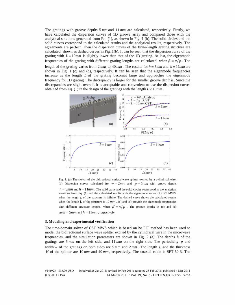
The gratings with groove depths 5 mm and 11 mm are calculated, respectively. Firstly, we have calculated the dispersion curves of 1D groove array and compared those with the analytical solutions generated from Eq. (1), as shown in Fig. 1 (b). The solid circles and the solid curves correspond to the calculated results and the analytical results, respectively. The agreements are perfect. Then the dispersion curves of the finite-length grating structure are calculated, shown as dashed curves in Fig. 1(b). It can be seen that the dispersion curve of the grating with 10L mm= is slightly lower than that of the 1D grating. At last, the eigenmode frequencies of the grating with different grating lengths are calculated, when pβ π= . The length of the grating varies from 2 mm to 40 mm . The results for 5h mm= and 11h mm= are shown in Fig. 1 (c) and (d), respectively. It can be seen that the eigenmode frequencies increase as the length L of the grating becomes large and approaches the eigenmode frequency for 1D grating. The discrepancy is larger for the smaller groove depth h . Since the discrepancies are slight overall, it is acceptable and convenient to use the dispersion curves obtained from Eq. (1) in the design of the gratings with the length 10L mm≥ .
Fig. 1. (a) The sketch of the bidirectional surface wave splitter excited by a cylindrical wire; (b) Dispersion curves calculated for 2w mm= and 5p mm= with groove depths
5h mm= and 11h mm= . The solid curve and the solid circles correspond to the analytical solutions from Eq. (1) and the calculated results with the eigenmode solver of CST MWS, when the length L of the structure is infinite. The dashed curve shows the calculated results when the length L of the structure is 10 mm . (c) and (d) provide the eigenmode frequencies with different structure lengths, when pβ π= . The groove depths in (c) and (d)
are 5h mm= and 11h mm= , respectively.
3. Modeling and experimental verification
The time-domain solver of CST MWS which is based on he FIT method has been used to model the bidirectional surface wave splitter excited by the cylindrical wire in the microwave frequencies, and the simulation parameters are shown in Fig. 2 (a). The depths h of the gratings are 5 mm on the left side, and 11 mm on the right side. The periodicity p and width w of the gratings on both sides are 5 mm and 2 mm . The length L and the thickness H of the splitter are 10 mm and 40 mm , respectively. The coaxial cable is SFT-50-3. The
#141923 - $15.00 USD Received 28 Jan 2011; revised 19 Feb 2011; accepted 25 Feb 2011; published 4 Mar 2011(C) 2011 OSA 14 March 2011 / Vol. 19, No. 6 / OPTICS EXPRESS 5263
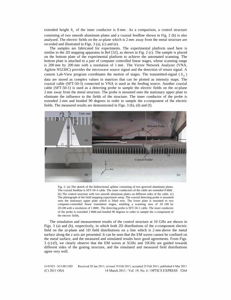
extended height fh of the inner conductor is 8 mm . As a comparison, a control structure consisting of two smooth aluminum plates and a coaxial feedline shown in Fig. 2 (b) is also analyzed. The electric fields on the xz-plane which is 2 mm away from the metal structure are recorded and illustrated in Figs. 3 (a), (c) and (e).
The samples are fabricated for experiments. The experimental platform used here is similar to the 2D mapping apparatus in Ref [32], as shown in Fig. 2 (c). The sample is placed on the bottom plate of the experimental platform to achieve the automated scanning. The bottom plate is attached to a pair of computer controlled linear stages, whose scanning range is 200 mm by 200 mm with a resolution of 1 mm . The Vector Network Analyzer (VNA, Agilent N5230C) provides the microwave source signal and the detection of return signal. A custom Lab-View program coordinates the motion of stages. The transmitted-signal ( 21S ) data are stored as complex values in matrices that can be plotted as intensity maps. The coaxial cable (SFT-50-3) connected to VNA is used as the feeding source. Another coaxial cable (SFT-50-1) is used as a detecting probe to sample the electric fields on the xz-plane 2 mm away from the metal structure. The probe is mounted onto the stationary upper plate to eliminate the influence to the fields of the structure. The inner conductor of the probe is extended 2 mm and bended 90 degrees in order to sample the z-component of the electric fields. The measured results are demonstrated in Figs. 3 (b), (d) and (f).
Fig. 2. (a) The sketch of the bidirectional splitter consisting of two grooved aluminum plates. The coaxial feedline is SFT-50-3 cable. The inner conductors of the cable are extended 8 mm . (b) The control structure with two smooth aluminum plates on different sides of the cable. (c) The photograph of the field mapping experiment setup. The coaxial detecting probe is mounted onto the stationary upper plate which is lifted now. The lower plate is mounted to two computer-controlled linear translation stages, enabling a scanning area of 20 cm by 20 cm with a resolution of 1 mm . The detecting probe is SFT-50-1 cable. The inner conductor of the probe is extended 2 mm and bended 90 degrees in order to sample the z-component of the electric fields.
The simulation and measurement results of the control structure at 10 GHz are shown in Figs. 3 (a) and (b), respectively, in which both 2D distributions of the z-component electric field on the xz-plane and 1D field distributions on a line which is 2 mm above the metal surface along the z axis are presented. It can be seen that the EM waves cannot be confined on the metal surface, and the measured and simulated results have good agreements. From Figs. 3 (c)-(f), we clearly observe that the EM waves at 5GHz and 10GHz are guided towards different sides of the grating structure, and the simulated and measured field distributions agree very well.
#141923 - $15.00 USD Received 28 Jan 2011; revised 19 Feb 2011; accepted 25 Feb 2011; published 4 Mar 2011(C) 2011 OSA 14 March 2011 / Vol. 19, No. 6 / OPTICS EXPRESS 5264
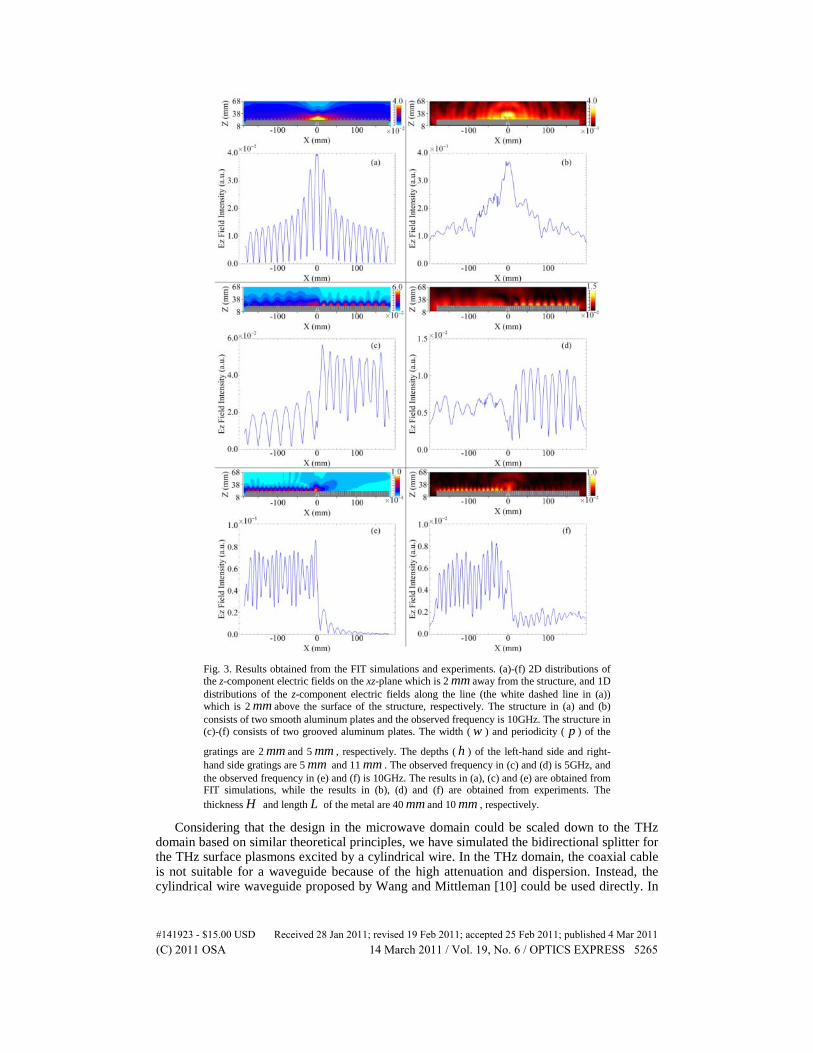
Fig. 3. Results obtained from the FIT simulations and experiments. (a)-(f) 2D distributions of the z-component electric fields on the xz-plane which is 2 mm away from the structure, and 1D distributions of the z-component electric fields along the line (the white dashed line in (a)) which is 2 mm above the surface of the structure, respectively. The structure in (a) and (b) consists of two smooth aluminum plates and the observed frequency is 10GHz. The structure in (c)-(f) consists of two grooved aluminum plates. The width ( w ) and periodicity ( p ) of the
gratings are 2 mm and 5 mm , respectively. The depths ( h ) of the left-hand side and right-hand side gratings are 5 mm and 11 mm . The observed frequency in (c) and (d) is 5GHz, and the observed frequency in (e) and (f) is 10GHz. The results in (a), (c) and (e) are obtained from FIT simulations, while the results in (b), (d) and (f) are obtained from experiments. The thickness H and length L of the metal are 40 mm and 10 mm , respectively.
Considering that the design in the microwave domain could be scaled down to the THz domain based on similar theoretical principles, we have simulated the bidirectional splitter for the THz surface plasmons excited by a cylindrical wire. In the THz domain, the coaxial cable is not suitable for a waveguide because of the high attenuation and dispersion. Instead, the cylindrical wire waveguide proposed by Wang and Mittleman [10] could be used directly. In
#141923 - $15.00 USD Received 28 Jan 2011; revised 19 Feb 2011; accepted 25 Feb 2011; published 4 Mar 2011(C) 2011 OSA 14 March 2011 / Vol. 19, No. 6 / OPTICS EXPRESS 5265

practice, a radially polarized surface wave on the cylindrical wire can be excited with high coupling efficiency through the use of a radially symmetric photoconductive antenna [26]. In the simulation, we put an outer shielding conductor at the bottom of the cylindrical wire. The outer conductor and the wire construct a short coaxial cable to introduce the radially polarized surface waves. The height, depth, and outer diameter of the outer conductor are 10 µm, 5 µm, and 200 µm, respectively. The diameter d of the cylindrical wire is set to 80 µm. The extended height fh of the wire above the grating surface is 80 µm. The periodicity p and slot width w of the gratings on both sides are 50 µm and 20 µm. The depths h of the gratings on the left and right sides are 50 µm and 110 µm, respectively. The length L and the thickness H of the splitter are 100 µm and 400 µm, and the simulation region is chosen as 3700µm ×300µm ×1480µm. The whole structure is surrounded by perfectly matched layer absorbers. The field distributions on the y=0 plane which passes the center of the cylindrical wire and the 1D distributions of electric field intensity on the line 2 µm above the surface grating are demonstrated in Fig. 4. From Fig. 4(a), we observe that most of the EM waves at 0.5 THz are guided towards the right-hand side gratings. From Fig. 4(b), it can be seen that nearly all EM waves at 1 THz are guided towards the left-hand side gratings. The field distributions of the bidirectional frequency splitter in the THz domain could be measured referring to the experimental setup in Ref [26].
Fig. 4. The FIT simulation results of the bidirectional surface wave splitter in the THz
frequencies: The 2D field distributions on the 0y = plane and the optical intensity (2E )
distribution on the line 2 mµ above the surface of the structure. The observed frequencies are
0.5 THz in (a) and 1.0 THz in (b), respectively. The length L of the metal splitter is 100 mµ ,
and the outer diameter d of the metal wire and the shielding conductor on the bottom are 80 mµ and 200 mµ , respectively.
4. Conclusions
In conclusions, we propose a bidirectional surface wave splitter excited by a cylindrical wire waveguide. The novelty of the proposed structure is the coupling mechanism from the cylindrical wire to the surface gratings. The FIT simulations and experiments are conducted to verify the splitter in the microwave frequency. We have shown that most EM waves at different frequencies are guided towards different directions along the gratings structures placed around the cylindrical wire. The measurement results have good agreements to the
#141923 - $15.00 USD Received 28 Jan 2011; revised 19 Feb 2011; accepted 25 Feb 2011; published 4 Mar 2011(C) 2011 OSA 14 March 2011 / Vol. 19, No. 6 / OPTICS EXPRESS 5266

simulation results. The proposed bidirectional surface wave splitter excited by a cylindrical wire could be extended to the THz frequencies.
Acknowledgments
This work was supported in part by a Major Project of the National Science Foundation of China under Grant Nos. 60990320 and 60990324, in part by the 111 Project under Grant No. 111-2-05, and in part by the National Science Foundation of China under Grant Nos. 60871016, 60901011, and 60921063.
#141923 - $15.00 USD Received 28 Jan 2011; revised 19 Feb 2011; accepted 25 Feb 2011; published 4 Mar 2011(C) 2011 OSA 14 March 2011 / Vol. 19, No. 6 / OPTICS EXPRESS 5267