bicycle facility types and design
TRANSCRIPT

Page | 106
his section serves as an introduction to the set of recommended facilities to be considered to enhance
bicycle safety, connectivity, and accessibility in Mercer County. The types of facilities are both related
to the existing conditions, strengths, and constraints discussed in chapter two, and reflective of established
guidelines and design recommendations.
The designs and recommendations to be considered are derived from a series of design and policy
manuals from both local and national contexts. These manuals aim to share standards, best practices, and
strategies for design and construction of bicycle facilities. The following section outlines the guides
referenced for development of these recommendations. It is important to note that many Mercer County
Roads have limited right-of-way and without massive corridor improvement projects and takings, the
County is mainly limited to existing road cartways & Right of Way. As such, staff will look at cost-effective
benefits to the general public and utilize context-sensitive solutions for the roadway environment.
It is important to note that there is significant room for flexibility in highway and roadway design and the
often used AASHTO Green Book is not a detailed design manual but a guidance document to be used by
users to make better informed decisions. There is a significant range of roadway conditions within Mercer
County so a “one size fits all” approach will not work. Context sensitive solutions must be used to reflect
the location and community. As a result, a range of design reference and guidance documents will be used
to design and implement bicycle facilities throughout the County. The following page refers to the most
current and applicable reference documents for Mercer County staff.
It is important to note that the County does however need to follow the Manual on Uniform Traffic Control
Devices (MUTCD) to stay in standards conformance with FHWA and can only follow recommendations if in
line with the MUTCD. The MUTCD is adopted by reference in accordance with Title 23, United States
Code, Section 109(d) and Title 23, Code of Federal Regulations, Part 655.603, and is approved as the
national standard for designing, applying, and planning traffic control devices. As the MUTCD and other
federal guidance changes, these recommendations may change during the life of this plan.
T
Bicycle Facility Types and Design
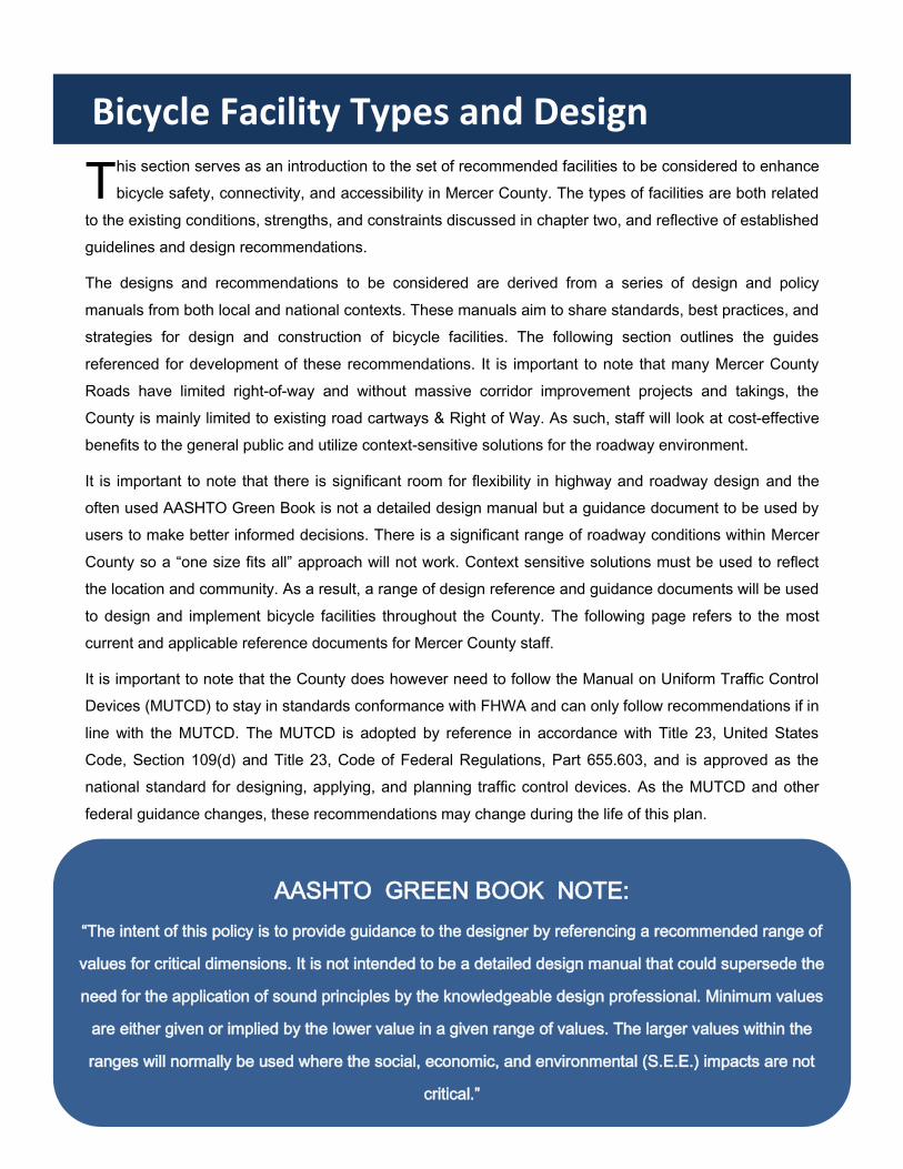
AASHTO GREEN BOOK NOTE:
“The intent of this policy is to provide guidance to the designer by referencing a recommended range of
values for critical dimensions. It is not intended to be a detailed design manual that could supersede the
need for the application of sound principles by the knowledgeable design professional. Minimum values
are either given or implied by the lower value in a given range of values. The larger values within the
ranges will normally be used where the social, economic, and environmental (S.E.E.) impacts are not
critical.”

Page | 107
Reference and Guidance Documents

Page | 108
1. Sharrows and Shared Lane Markings
2. Bikable Paved Shoulders *(temporary or when cartway restricted)
3. Standard Bike Lanes
4. Buffered Bike Lanes (Painted and Rumble)
5. Two-Way Cycle Tracks & Hybrid Bike Lanes
6. Separated/ Protected Bike Lanes
7. Multi-Use Path and Shared-Use Paths
8. Through Lanes
9. Combines Bike Lane/ Turn Lanes
10. Intersection Crossings
Intersection Bike Box
Two-Stage Turn Queue Box
Protected Intersection
Signal Timing and Cycle Length
Leading Bike/ Pedestrian Interval
Signalized Turns
Bike Boxes and Two-Stage Bike Turn Boxes
11. Road Diet and Lane Diets
12. Driveway Design
13. Bikeway through Existing Bridge and Underpass/ Tunnel Considerations
14. Entrance/ Exit Ramp Designs
15. Midblock Crossings
16. Pavement Markings, Wayfinding, and Signage Standards (MUTCD)
Bicycle Facilities To Be Considered

Page | 109
A sharrow, or shared lane marking, is a street
marking indicating that a lane should be used by both
bicyclists and motor vehicles. The image, a bicycle
below two wide directional arrows, identifies proper
bicyclist positioning within the cartway. Sharrows can
also be helpful tools for wayfinding and signaling
directionality.
Benefits
> Does not require additional street space.
> Reduces bicyclists riding against motor vehicle traffic.
> Provide wayfinding and directionality guidance for
bicyclists.
Considerations
> “May Use Full Lane” Signs encourage bicyclists to
use the full lane to discourage unsafe within-lane
passing
>Bike-and-chevron lane sharrow marking were
approved for use within the US per the 2009 MUTCD.
> Frequency of sharrows should be increased when
being used to fill gaps in other facilities, or in areas with
high motor vehicle volume/speed.
> Placing sharrows in the center of a travel lane when
possible will reduce marking wear from motor vehicle
tires.
> The “door zone” should be avoided when determining
lateral sharrow placement.
> In the absence of on-street parking, sharrows should
be placed so as to avoid gutters, seams and other
hazardous obstacles.
> The chevron orientation may be adjusted to serve
wayfinding purposes.
> Color may be used to enhance the visibility of the
sharrow.
Design Recommendations
-Sharrow spacing, high volume street: 50-100’
-Sharrow spacing, low volume street: 250’ or more
-Minimum distance from curb: 4’ (no parking)
-Shared Lane Marking (MUTCD 9C-9)
-MUTCD Sign Options: R4-11 > W11-1 & W16-1
Sharrow
IMAGE : commercial
Source: Town of Frisco, CO
Source: NJDOT Complete Streets Design Guide

Page | 110
Paved shoulders may be used as space for bicyclists
and pedestrians to travel adjacent to a motor vehicle
lane and provide motorists with an area to pull over in
emergencies. In cases of incomplete bicycle
networks, paved shoulders can serve as an unofficial
connection until such connection can be made.
Benefits
> May not require additional street space.
> Reduces bicyclists riding against motor vehicle traffic.
> Provides wayfinding and directionality guidance for
bicyclists.
Considerations
> Physical separation, such as rumble strips in the
buffer area, can be used to alert drivers that they are
encroaching on the bike lane and increase bicyclist
comfort/safety.
> Bicyclist signage is not required, but could be used to
signify a bicycle route.
> The solid shoulder line should be discontinued at
intersections and major driveways. Dotted white lines
may be used to extend the shoulder and signify bicycle
travel space through these areas.
> Provide more than the minimum 4’ shoulder width
when possible to increase bicyclist and pedestrian
comfort.
> Contrasting colors may be used to distinguish the
shoulder from the motor vehicle lanes.
> Paved shoulders should be considered during routine
roadway maintenance, reconstruction, and in new
constructions.
Design Recommendations
-Paved shoulders can be considered as a precursor
to dedicated bicycle facilities and marked routes
-Minimum shoulder width: 4’ (wider shoulders and
rumble strips should be considered on roads with
higher speeds AADTs)
-If rumble strips included, place rumble strips to
overlap with the roadway edge line
>Rumble lines should provide a 12’ gap every 40’-
60’ to allow for bicycle access into and out of the
shoulder
12 inch spacing center to center
6-8 inches long perpendicular to roadway
6 inches wide, measured parallel to roadway
3/8 inch deep
Bikable Paved Shoulder
Above: Children riding bikes in shoulder of Pond Road in Robbinsville, NJ.
Source: Jerry Foster
Source: Alta Planning + Design (CC-BY-SA)

Page | 111
Standard bicycle lanes are delineated by solidly
striped lines and can be marked with a combination
of bicycle symbols, directional arrows, and words.
Lanes are located between a vehicular travel lane
and parking or the curb, directing bicyclists to move
with traffic.
Benefits
> Further separates sidewalks, if present, from motor
vehicle travel lanes.
> Provides a space exclusively for bicyclist travel.
> Establishes a level of predictability for bicycle and
vehicle placement and behavior.
Considerations
> Markings for bike lanes should not be dotted when
passing through a driveway crossing, as driveways are
not considered intersections (MUTCD 2009, AASHTO
Bike Guide 2012).
> When determining the width of bike lanes, one should
take into account the presence of curb faces, guardrails,
on-street parking, and other features.
> Larger bike lanes (~7’) may enable parking or driving
within the lane. In this case, consider adding a buffer
zone to clarify.
> When the bike lane is adjacent to a guard rail or
physical barrier, add two feet to the bike lane width.
> A distance of four inches should be used to separate
a bike lane from a parking lane.
> Obstacles in the bicycle lane such as gutters,
drainage inlets, and utility covers should be designed so
as not to interfere with bicycle tires. These features
should be oriented appropriately and level with the
ground.
Design Recommendations
-Lane width: 4’-6’
-Cartway width: 28’ min.
-Line width: 6”-8”
>Green paint can be an appropriate tool in areas
where motor vehicles need to cross bike lanes, such
as merging. (MUTCD Interim Approval)
Standard Bicycle Lane
Above: Standard bike lane in West Windsor, NJ Source: Jerry Foster
Source: Chicago Department of Transportation

Page | 112

Page | 113
To increase separation between bikers and motor
vehicle traffic, bicycle lanes may be enhanced with a
buffer. Buffers can include visual separation, such as
a painted area marked with longitudinal stripes, or
physical separation such as rumble strips to alert
drivers when they are entering the bike lane. Buffer
treatments improve safety and bicyclist comfort on
roadways with high traffic volumes and speed, as
well as those with trucks or oversized vehicles.
Benefits
> Expands the benefits of a conventional bike lane by
providing greater distance between bicyclists and motor
vehicles compared to conventional bike lanes.
> Allows space for bicyclists to pass each other without
having to enter the vehicle travel lane.
>Distinguishes larger bike lanes from travel or parking
lanes.
> Can create separation between bicyclists and ‘door
zone’.
Considerations
> Physical separation, such as rumble strips in the
buffer area, can be used to alert drivers that they are
encroaching on the bike lane and increase bicyclist
comfort/safety.
> A bike lane should be transitioned to a through bike
lane when a right turn only lane approaches, placed to
the left of the turn lane. If space does not permit, a
shared bike lane/turn lane should be used.
> At intersections without a right turn only lane, buffer
markings should become a conventional dashed line.
Bike boxes may also be helpful in these scenarios.
>A 6”-8” solid white line may be painted to mark the
separation from a motor vehicle travel lane.
Design Recommendations
-Lane width: 4’-6’
-Cartway width: 35’ min
-Buffer width: 12” White Line or other buffer ≥18”
>Optional rumble lines should provide a 12’ gap every 40’-
60’ to allow for bicycle access into and out of their lane.
-A buffered bike lane is allowed as per MUTCD guidelines
for buffered preferential lanes (section 3D-01).
-Buffer width: 3 ft. min. for hatching within buffer
“When crosshatch markings are used in paved areas that
separate traffic flows in the same general direction, they
shall be white and they shall be shaped as chevron
markings, with the point of each chevron facing toward
approaching traffic…” (MUTCD section 3B.24)
Buffered Bicycle Lane
Above: Buffered bike lane on Warren Street in the City of Trenton, NJ.
Source: Jerry Foster
Above: Double White Line Buffered Bike Lanes on Scotch Road, Ewing.

Page | 114
Page | 115
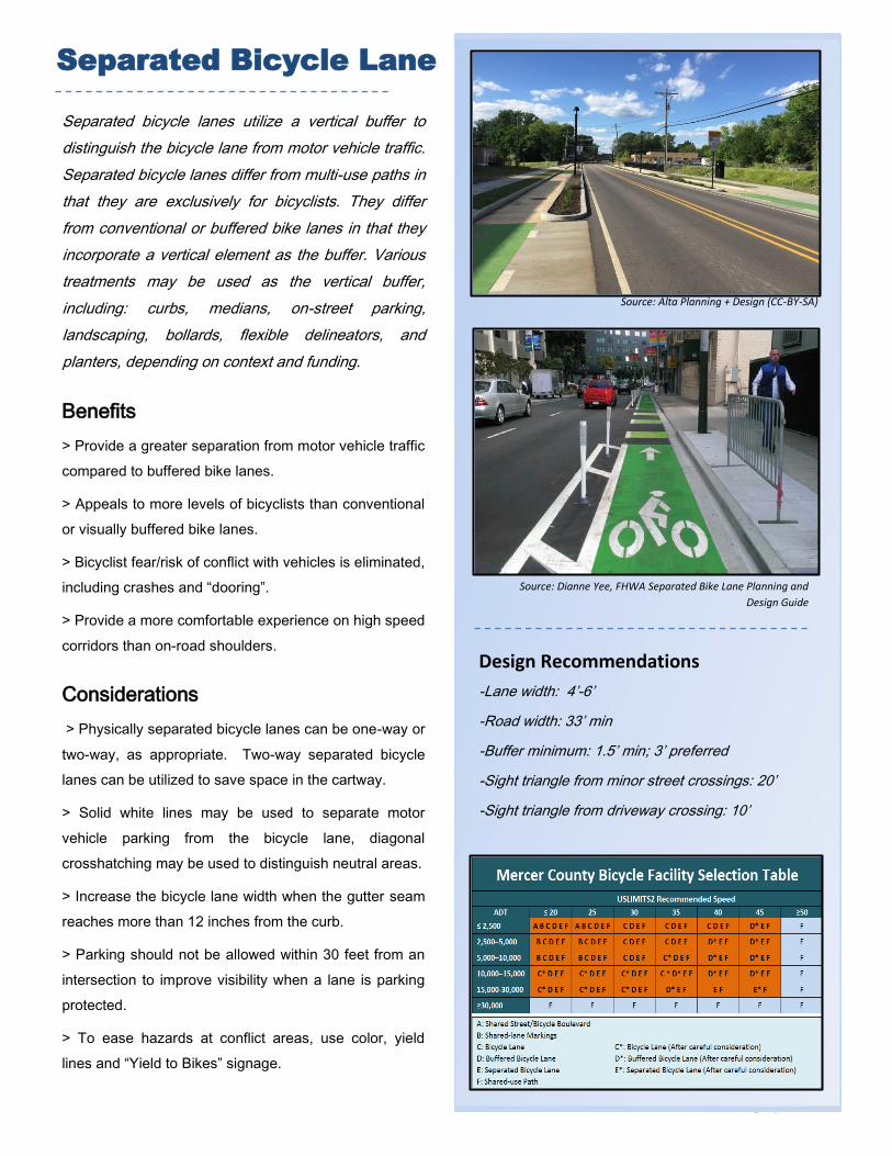
Separated bicycle lanes utilize a vertical buffer to
distinguish the bicycle lane from motor vehicle traffic.
Separated bicycle lanes differ from multi-use paths in
that they are exclusively for bicyclists. They differ
from conventional or buffered bike lanes in that they
incorporate a vertical element as the buffer. Various
treatments may be used as the vertical buffer,
including: curbs, medians, on-street parking,
landscaping, bollards, flexible delineators, and
planters, depending on context and funding.
Benefits
> Provide a greater separation from motor vehicle traffic
compared to buffered bike lanes.
> Appeals to more levels of bicyclists than conventional
or visually buffered bike lanes.
> Bicyclist fear/risk of conflict with vehicles is eliminated,
including crashes and “dooring”.
> Provide a more comfortable experience on high speed
corridors than on-road shoulders.
Considerations
> Physically separated bicycle lanes can be one-way or
two-way, as appropriate. Two-way separated bicycle
lanes can be utilized to save space in the cartway.
> Solid white lines may be used to separate motor
vehicle parking from the bicycle lane, diagonal
crosshatching may be used to distinguish neutral areas.
> Increase the bicycle lane width when the gutter seam
reaches more than 12 inches from the curb.
> Parking should not be allowed within 30 feet from an
intersection to improve visibility when a lane is parking
protected.
> To ease hazards at conflict areas, use color, yield
lines and “Yield to Bikes” signage.
Design Recommendations
-Lane width: 4’-6’
-Road width: 33’ min
-Buffer minimum: 1.5’ min; 3’ preferred
-Sight triangle from minor street crossings: 20’
-Sight triangle from driveway crossing: 10’
Separated Bicycle Lane
Source: Alta Planning + Design (CC-BY-SA)
Source: Dianne Yee, FHWA Separated Bike Lane Planning and
Design Guide

Page | 116
Two-way cycle tracks are a physically separated set
of bike lanes that allow bicycle movement in both
directions on the same side of a street. Two-way
cycle tracks tend to be good for bicyclists of all
experience levels due to their physical separation
from traffic, their ability to avoid the risk of being
“doored” by a parked vehicle, and because they
reduce indirect travel by allowing movement against
the direction of one-way streets.
Benefits
>Provide dedicated and protected space to a cyclist,
which improves their perceived feelings of safety.
> Reduces risk of dooring.
>Attractive to bicyclists with a range of ages and
abilities.
Considerations
>Two way Cycle Tracks may be configured as:
A protected cycle track at street level with a
barrier such as a flexible delineator and/or with
parking.
Raised cycle tracks provide vertical separation
from adjacent vehicular traffic.
>Function better on streets with fewer driveways and
curb cuts and should be placed on the side of street
with more desired destinations.
>Useful on streets with higher traffic volumes.
>Useful on higher stress streets with higher speeds and
higher traffic volumes.
>Intersection controls should be oriented towards
bicyclists going in both directions.
Design Recommendations
-Minimum Track Width 8’, Desired Width: 12’.
-When parking protected, 3’ buffer is need between
parked cars and cycle track.
-Dashed yellow centerline should be used to
separate lanes.
-Approximately 10’-20’ sight triangles are
recommended at driveways and intersections.
Parking should be prohibited near these driveways.
-Color, yield markings, and signage should be used
to identify conflict zones.
-A “ONE WAY” sign (MUTCD R6-1, R6-2) should be
provided if located on a one way street.
-A “DO NOT ENTER” with “EXCEPT BIKES” sign
(MUTCD R5-1) sign should be provided.
Two-Way Cycle Track
Above: Photo simulation of potential two-way cycle track on Lamberton
Street in the City of Trenton. Source: NV5/ D&R Greenway Land Trust
Source: Dianne Yee, FHWA Separated Bike Lane Planning and Design
Guide

Page | 117
A sidepath is a bidirectional shared use path located
immediately adjacent and parallel to a roadway and
provides a travel area separate from motorized traffic
for bicyclists, pedestrians, skaters, wheelchair users,
joggers, and other users. Sidepaths can offer a high-
quality and low-stress experience for users of all
ages and abilities using the network for transportation
or recreation as compared to on-roadway facilities in
heavy traffic environments
Benefits
>Encourages bicycling and walking in areas where
high-volume and high-speed motor vehicle traffic would
otherwise discourage it.
>Appropriate for walkers and bikers, as well as
wheelchairs, roller blades, skateboards, etc.
> Provides a more appropriate facility for users of all
ages and abilities than shoulders or mixed traffic
facilities on roads with moderate or high traffic intensity.
>Very supportive of rural character when combined with
vegetation.
Considerations
>Utilize medians and raised crossings at intersections
to prioritize path travel and increase safety/comfort of
path users.
>Widths and design details of sidepath elements may
vary in response to the desire for increased user
comfort and functionality, the available right-of-way, and
the need to preserve natural resources.
>Landscaping can be used to further increase the
separation between a path and the roadway, and add to
the recreational appeal of the facility.
>When appropriate, sidepaths should transition to on-
road facilities when the path ends.
>Minimum recommended pathway width is 10’. In low-
volume situations and constrained conditions, the
absolute minimum sidepath width is 8’.
Multi-Use Sidepath
-Schuylkill River Multi-Use Trail Source: Eagle Transfer Corporation
Above: Sidepath in Lawrence Township, NJ Source: Jerry Foster
Above: Penn Street Multi-Use Path in Philadelphia Source: DRWC

Page | 118
Design Recommendations
-Multi-Use sidepaths can be incorporated at any speed
or volume of adjacent roadway.
-Intersections need to be carefully designed and other
guides should be referenced for additional information.
-10’ width is recommended in most situations and will
be adequate for moderate to heavy use.
-A “BIKES YIELD TO PEDS” (R9-6) sign may be used
at the entrances of path segments to remind bicyclists
of the requirement to yield.
-A “RIGHT TURN YIELD TO PEDESTRIANS” sign
(MUTCD R10-15) should be provided at road crossings
with right turn intersections.
-Preferred minimum separation width is 6.5’ and
minimum separation distance is 5’
-Where a sidepath terminates, it may be necessary for
path users to transition to a facility on the opposite side
of the road.
-Paths with a high volume of bidirectional traffic should
include a centerline. When striping is required, use a 4
inch broken yellow center line stripe with 4 inch solid
white edge lines. Solid center lines can be provided on
tight or blind corners and on the approaches to roadway
crossings.
Multi-Use Sidepath
Source: Alta Planning + Design (CC-BY-SA)
Recommended Sidepath Dimensions To Be Considered (adjacent to roadway. Source: FHWA Small Town and Rural Design Guide)
Barriers can be used between the sidepath and the roadway where a 5’ separation cannot be provided. In extremely constrained conditions for short distances, on-roadway rumble strips may be used as a form of separation. Source: FHWA Small Town and Rural Design Guide
Above: Sidepath Separation Distance at Road Crossings (left) and transition from a sidepath on one side to shoulders on each side of the road (right). Source: FHWA Small Town and Rural Design Guide

Page | 119
Multi-Use Sidepaths require special attention at
intersections and crossings, especially at mid-block
crossings where motorists may be unaware of them. In
the State of New Jersey, vehicles must yield the right of
way to pedestrians at marked crosswalks and at
intersections where stop signs or flashing red signals
are in place. Pedestrians must yield the right-of-way to
vehicles when crossing outside of a marked crosswalk
or an unmarked crosswalk at an intersection with no
stop sign. In many instances, multi-use paths will need
to cross a County Highway away from a marked
intersection.
Considerations
>Designs should consider the desire for natural
directional flows, and the potential for conflicts with
adjacent traffic. Use should be made of median islands
and horizontal deflection of the roadway travel lanes to
slow motor vehicle traffic and offer improved crossing
conditions for path users.
>A basic marked shared use path crossing consists of a
marked crosswalk, plus signs and other markings to
slow or stop traffic.
>High-visibility crosswalk markings are the preferred
marking type at uncontrolled marked crossings.
Transverse lines are “essentially not visible” when
viewed from a standard approaching vehicle.
>At high-speed and high-volume intersections, it may
be necessary to make full intersection improvements.
>Visual obstructions should be low to provide
unobstructed sight of the crossing from the major street.
Both motorists and path users should have a clear and
unobstructed view of each other at intersections and
driveways.
Multi-Use Sidepath Intersections and Crossings
FHWA Safety Effects of Marked Crosswalks at Uncontrolled Locations 2005
recommends crossing enhancements on high-speed and high-volumes
roadways where crosswalk markings alone are not a viable safety measure.
Source: FHWA
Standard crosswalk striping, shown at top, often has very poor visibility to motorists, particularly on higher speed roadways or where the striping has faded. Ladder or Continental striping is preferable in most situations because it significantly improves the visibility of the crossing to motorists and maintains this visibility better as it ages. Source: NJDOT Complete Streets Design Guide
Source: Press of Atlantic City

Page | 120
FHWA’s report Safety Effects of Marked Crosswalks at Uncontrolled Locations, 2005 recommends crossing
enhancements on high-speed and high-volumes roadways where crosswalk markings alone are not a viable safety
measure. There are several methods to create these safer crossings. For crossings on low-speed and low-volume
roads, a simple marked crossing consisting of a marked crosswalk, signs and other marking to slow traffic, such as
below. Crosswalk markings are necessary to establish a legal crosswalk at areas away from intersections. Crossing
sign assemblies and advance crossing sign assemblies using W11-15 and W16-7P signs should be used to warn
users of the crossing location and high-visibility crosswalk markings should be used.
For higher-speed and higher-volume roads where greater visibility or traffic control is desired, a rectangular rapid flash
beacon (RRFB) or pedestrian hybrid beacon (PHB) may be used. Where drivers fail to stop for pedestrians and
compliance is low, RRFBs should also be incorporated. RRFBs are a yield enhancement device for use at
uncontrolled crossings. They may be configured with solar power where it is the most cost-effective option. See an
updated FHWA Interim Approval (March 2018) for guidance on the application of RRFBs. “State Law: Stop for
Pedestrian” may also be placed to advise drivers of this requirement.
Multi-Use Sidepath “Mid-Block” Crossings

Page | 121
On treacherous and hard to cross multilane streets with high volumes and few gaps for crossing, a Pedestrian Hybrid
Beacon (PHB) may be used to increase yielding rates. A pedestrian hybrid beacon, also known as a high intensity
actuated crosswalk (HAWK), is a pedestrian actuated traffic control device for mid-block pedestrian crossing
locations. They enable pedestrians to cross high-speed and high-volume roadways while traffic is stopped. As the
name implies, it is essentially a hybrid between a RRFB and a full traffic signal. It provides planners and engineers
with an intermediary option for locations that do not meet requirements for a traffic signal warrant, but where traffic
conditions exceed the limitations of an RRFB. PHB’s provide a red signal indication to drivers, and create yielding
rates similar to that of a conventional traffic signal. PHBs are particularly useful on undivided roadways with multiple
lanes in any one direction. PHBs are an FHWA Proven Safety Countermeasure.
For many road segments, crossing islands or pedestrian refuge islands can be considered. These median islands are
beneficial on roadways with high volumes and/or high speeds, and on roadways with three or more travel lanes.
Median islands particularly benefit people who may travel slower, such as children, older adults, and people with
disabilities. They enable pedestrians to make a crossing in two stages—crossing one direction of vehicular travel
lanes, pausing at the island, and then completing the crossing. This reduces the exposure time of pedestrians to
vehicular traffic. Crossing islands should be a minimum of 6 feet wide, with a preferred width of 8 to 10 feet, and a
minimum of 6 feet long. They should also have a “nose” that extends beyond the crossing to protect pedestrians from
turning vehicular traffic. Median islands are an FHWA Proven Safety Countermeasure which the FHWA identified as
an effective, proven, tested and studied tool to promote safety.
Multi-Use Sidepath “Mid-Block” Crossings

Page | 122
Additional Design
Considerations and Facilities

Page | 123
A through bike lane uses dashed lines and/or colored
lane to position bicyclists to the left of right turn lanes
or to the right of left turn lanes and gets bicycles
across dangerous or busy intersections.
Benefits
>Reduces conflict between turning motorists and
cyclists going straight.
>Provides more predictable travel movements for all
users.
>Alerts motorists to yield to merging traveling.
Design Recommendations
-Desired width of a through lane is 4’-6’.
-Dotted white line should be 6’’ wide and 2 ‘long with 6’
gap between dashes.
-Dashed lines should begin a minimum of 50’ before an
intersection, 100’ if on a high volume corridor.
-The through bike lane shall be placed to the left of the
right-turn only lane.
Through Lanes
Source: NACTO, Boulder, CO
Source: NACTO, Portland, OR
Source: NACTO, Urban Street Design Guide

Page | 124
A combined bike sharrow lane / turn lane uses signage and
bike sharrow markings within a turn lane to suggest a route
to delineate space for cyclists and to guide them through the
intersection. Sharrow markers also provide a visual warning
to vehicles to watch for cyclists.
Benefits
>Helps to position and guide cyclists through intersections by
aligning them to the left of right-turning vehicles and
encourages motorists to yield to cyclists.
>Reduces risk of “right hook” collisions by keeping bikes left of
vehicles making right turn. Cheapest alternative for streets with
limited cartway.
Design Recommendations
-Only MUTCD sharrow markings (with no alterations) shall be
used to clarify bicyclist positioning within the combined lane. No
bicycle lane markings or lines shall be used to attempt to create
and establish a bike lane.
-Width of combined lane should be 9 feet minimum, 13 feet
maximum. A full bicycle through lane can be accommodated if
the vehicle right-turn only lane can be made 14 feet or wider.
Combined Right Turn / Bike Sharrow
Source: SF Municipal Transportation Authority
Source: NACTO
Source: NACTO, Urban Street Design Guide (left); SF Municipal Transportation Agency (right)
-Chapter 5.3 of the NJDOT Roadway Design Manual: On land service highways states that where it is not practical to
provide a shoulder adjacent to the outside lane (design exception required), the outside lane width shall be 15 feet to
accommodate bicyclists. Where alternate bike access is provided, the outside lane width should be 1 foot wider than the
adjacent through lane width. The designer should strive to accommodate the bicyclist and pedestrian on all projects.

Page | 125
Intersection crossing markings help to guide
bicyclists through intersections by providing clear and
direct paths using arrows and dashes. These
marking are also helpful in that they make bicyclists’
paths more predictable for drivers, reinforcing that
they have priority over turning vehicles and bringing
attention to their presence.
Benefits
>Reduces conflict between turning motorists and
cyclists going straight and Increases the visibility of
bicyclists.
>Provides more predictable travel movements for all
users.
>Guides bicyclists through the intersection in a straight
and direct path.
> Reinforces that through bicyclists have priority over
turning vehicles or vehicles entering the roadway (from
driveways or cross streets).
>Reduces bicyclist stress by delineating the bicycling
zone.
Intersection Crossings
Above: Types of possible markings Source: NJDOT Complete Streets Guide
Source: NACTO, Chicago, IL
Example of Intersection Markings Source: NACTO, Urban Street Design

Page | 126
Design Recommendations
-Dotted lines shall bind the bicycle crossing space.
-Pavement markings extended into or continued
through an intersection or interchange area shall be the
same color and at least the same width as the line
markings they extend.
-Striping width shall be a minimum of 6 inches adjacent
to motor vehicle travel lanes and shall otherwise match
the width and lateral positioning of leading bike lane
striping, except when using elephant’s feet markings.
-Dotted lines should be 2 foot lines with 2 to 6 foot
spacing. Markings should be white, skid resistant and
retro-reflective.
-Crossing lane width should match width and
positioning of the leading bike lane.
-On crossings of two-way paths and cycle tracks,
markings should indicate that there is two-way traffic
either by marking the path center line through the
intersection, or by marking bicycle silhouettes and / or
chevrons in opposite directions in the two lanes. See
Two-Way Cycle Tracks.
-Chevrons may be used for increased visibility within
conflict areas or across entire intersections. Placement
shall be in the middle of the moving lanes, and close to
crosswalks.
-Shared lane markings (MUTCD Figure 9C-9) may be
used for increased visibility within conflict areas or
across entire intersections. Placement shall be in the
middle of the moving lanes, and close to crosswalks.
Intersection Crossings
Above: Crossing of side street in Trenton, NJ Source: Jerry Foster
Source: NACTO, Urban Street Design Guide; Missoula, MT
Source: NACTO, Urban Street Design Guide; NYC, NY

Page | 127
A bike box is a designated area at the head of a
traffic lane at a signalized intersection that provides
bicyclists with a safe and visible way to get ahead of
queuing traffic during the red signal phase.
Benefits
>Groups bicyclists together to clear an intersection
quickly, minimizing impediment to transit or other traffic.
>Provides more predictable travel movements for all
users.
>Helps prevent ‘right-hook’ conflicts with turning
vehicles at the start of the green indication.
> Reduces signal delay for bicyclists.
>Facilitates bicyclist left turn positioning at intersections
during red signal indication. This only applies to bike
boxes that extend across the entire intersection.
>Facilitates the transition from a right-side bike lane to a
left-side bike lane during red signal indication. This only
applies to bike boxes that extend across the entire
intersection.
Intersection Bike Box
Source: NJDOT Complete Streets Guide
Source: NACTO, Portland, OR
Source: NACTO, Urban Street Design Guide

Page | 128
Design Recommendations
-A box formed by transverse lines shall be used to hold
queuing bicyclists, typically 10-16 feet deep. Deeper
boxes show less encroachment by motor vehicles.
-Stop lines shall be used to indicate the point behind
which motor vehicles are required to stop in compliance
with a traffic control signal.
-Pavement markings shall be used and centered
between the crosswalk line and the stop line to
designate the space as a bike box. The marking may be
a Bike Symbol (MUTCD 9C-3A) or Helmeted Bicyclist
Symbol (MUTCD 9c-3B.)
-At intersections that currently permit right turns on red
signal indications, a “No Turn on Red” sign shall be
installed overhead to prevent vehicles from entering the
Bike Box.
-A “Stop Here on Red” sign should be post-mounted at
the stop line to reinforce observance of the stop line.
-Colored pavement should be used as a background
color within the bike box to encourage compliance by
motorists.
-An ingress lane should be used to define the bicycle
space. Colored pavement may be used. When color is
used, length shall be 25 to 50 feet to guarantee bicycle
access to the box.
-An egress lane should be used to clearly define the
potential area of conflict between motorists and
bicyclists in the intersection when intersection is
operating on a green signal indication.
-A “Yield to Bikes” sign should be post-mounted in
advance of and in conjunction with an egress lane to
reinforce that bicyclists have the right-of-way going
through the intersection.
Source: NACTO, Madison, WI
Source: NACTO, Tucson, AZ
Source: NACTO, Austin, TX

Page | 129
A two-stage bike turn box provides a more
comfortable and safe way for bicyclists to cross multi-
lane streets with high vehicle speeds or volumes.
Similar to a jug-handle for motor vehicles, bicyclists
complete a left turn by dividing it into two
movements. Bicyclists first proceed through the
intersection with traffic to a bike box on the far side of
the intersection, where they position themselves in
front of the traffic queue on the cross street. When
the traffic signal turns green for the cross street, they
cycle across the intersection with traffic, completing
the left turn.
Benefits
>Improves bicyclist ability to safely and comfortably
make left turns.
>Provides a formal queuing space for bicyclists making
a two-stage turn.
>Reduces turning conflicts between bicyclists and motor
vehicles.
>Prevents conflicts arising from bicyclists queuing in a
bike lane or crosswalk.
Two-Stage Turn Queue Boxes
Source: City of Columbus, Ohio
Source: NJDOT Complete Streets Guide
Source: City of Columbus, Ohio

Page | 130
A protected intersection extends the physical barrier
of the protected bike lane into the intersection,
creating a clear and safe, continuous path of travel
for all modes. Protected intersections have four main
design elements: a corner refuge island, a forward
stop bar for cyclists, a setback bicycle and pedestrian
crossing, and bicycle-friendly signal phasing. The
corner refuge island is a physical barrier that protects
people on bikes from cars making turns. After
yielding to pedestrians, cyclists can either turn right
safely or continue into the intersection past the
crosswalk to the forward stop bar, where they can
wait at a red light buffered from vehicles by the
refuge island.
Benefits
>Improves bicyclist ability to safely and comfortably
make left turns.
>Reduces turning conflicts between pedestrians,
bicyclists and motor vehicles.
>Reduces crossing distances for bicyclists and
pedestrians.
Protected Intersection
Source: Chicago Department of Transportation
Source: Alta Planning, Salt Lake City
Source: Alta Planning

Page | 131
A lane diet is a treatment that involves decreasing
the size of lanes, rather than the number, to reduce
vehicle speeds and encourage yielding. The size of
the lane that is removed may be reallocated as a
bicycle facility. According to the AASHTO Green
Book, for rural and urban arterials, lane widths may
vary from 10 to 12 feet. Ten feet is the recommended
minimum width for travel lanes and turn lanes, while
eleven feet is recommended for areas frequented by
trucks and buses.
Benefits
>Narrower lanes typically result in lower speeds due to
their effect on driver psychology, which can help to
reduce the severity of crashes.
>Narrowed lanes help to create space for bicycle
facilities.
>According to FHWA, there are “No significant safety or
capacity differences between 10–foot and 12-foot wide
travel lanes under most urban and suburban
conditions.”
Design Recommendations
-Lanes greater than 11 feet should not be used as they
may cause unintended speeding and assume valuable
right of way at the expense of other modes.
-Parking lane widths of 7–9 feet are generally
recommended. Cities are encouraged to demarcate the
parking lane to indicate to drivers how close they are to
parked cars.
-For multi-lane roadways where transit or freight
vehicles are present and require a wider travel lane, the
wider lane should be the outside lane (curbside or next
to parking).
Lane Diets
Source: NJDOT Complete Streets Design Guide
Source: John Keating, Overland Park, Kansas
Before
After

Page | 132
Generally, road diets involve reallocating roadway
space by removing vehicle travel lanes from a
roadway and using that space for other modes or
uses. One of the most common conversions is
moving from a four-lane road to one with two through
lanes and a center two-way left-turn lane, an
example of which is shown to the right. By reducing
lanes, other features such as bicycle lanes, widened
sidewalks, or landscaped boulevards can be added
to the right-of-way, resulting in fewer vehicle conflicts
and improved safety outcomes.
Benefits
> The space provided by removing a travel lane can be
used to create bicycle lanes on both sides of the
cartway.
> Bike lanes provide greater separation between motor
vehicles and the sidewalk, creating a more comfortable
pedestrian environment.
> Center turn lanes reduce crashes and conflicts with
turning vehicles without reducing throughput. Center
turn lanes have been shown to reduce crashes between
19% and 47%.
Design Recommendations
-Lane reductions on roadways with more than 20,000
AADT should be studied to assure that driveway access
and signals are appropriate for higher volumes.
Roadways with up to 25,000 AADT have successfully
road dieted.
-Travel lane widths can be 10’ to 12’.
-Width of center lane is 10’ to 16’ depending on types of
vehicles using street.
Road Diet
Source: Michael Ronkin, Main Street, Pottstown, PA
Source: NJDOT Complete Streets Guide
After
Before
Before
After

Page | 133
Driveways pose an often unforeseen danger to
pedestrians and cyclists in that many are designed
as intersections which promote high-speed turns and
increase the likelihood that drivers will not stop for
pedestrians or give cyclists the right of way.
Benefits
> Proper driveway design discourages high-speed turns
and forces drivers to make slower turning movements.
This allows drivers to better identify pedestrians and
cyclists.
> Proper design is especially critical to safety for multi-
use paths and facilities which include cyclists.
Design Recommendations
-According to ADAAG, driveways should be designed
with the following guidance:
Cross slope should not exceed 2 percent.
Changes in level or grade should be flush with
a ¼-inch maximum gap in surface rise.
The slope of the driveway apron flare should
not exceed 10 percent.
Sidewalk grade should not exceed 5 percent.
-Max grade differential between driveway apron and
street shall be no more than 8%.
Where volumes are high, alternative B is preferred.
Driveway Design
Source: NJDOT Complete Street Design Guide
Source: NJDOT Complete Streets Guide
Source: NJDOT Complete Street Design Guide
Page | 134
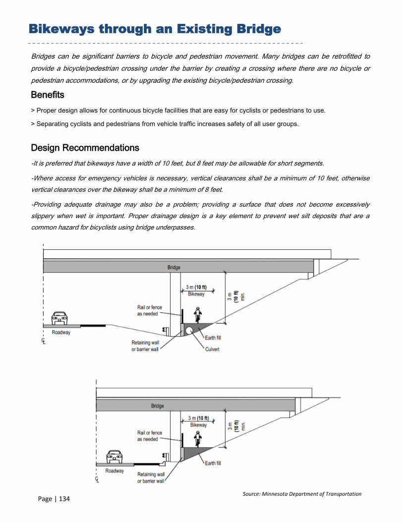
Bridges can be significant barriers to bicycle and pedestrian movement. Many bridges can be retrofitted to
provide a bicycle/pedestrian crossing under the barrier by creating a crossing where there are no bicycle or
pedestrian accommodations, or by upgrading the existing bicycle/pedestrian crossing.
Benefits
> Proper design allows for continuous bicycle facilities that are easy for cyclists or pedestrians to use.
> Separating cyclists and pedestrians from vehicle traffic increases safety of all user groups.
Design Recommendations
-It is preferred that bikeways have a width of 10 feet, but 8 feet may be allowable for short segments.
-Where access for emergency vehicles is necessary, vertical clearances shall be a minimum of 10 feet, otherwise
vertical clearances over the bikeway shall be a minimum of 8 feet.
-Providing adequate drainage may also be a problem; providing a surface that does not become excessively
slippery when wet is important. Proper drainage design is a key element to prevent wet silt deposits that are a
common hazard for bicyclists using bridge underpasses.
Bikeways through an Existing Bridge
Source: NJDOT Complete Street Design Guide
Source: NJDOT Complete Streets Guide
Source: Minnesota Department of Transportation
Page | 135
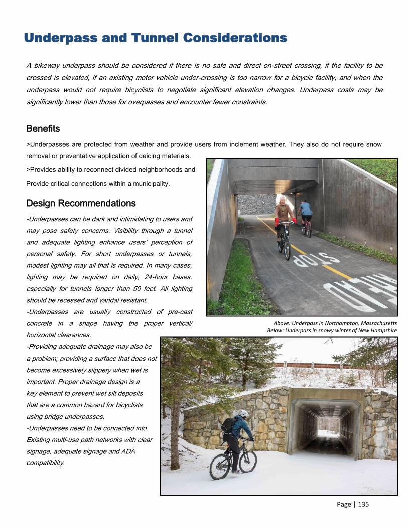
A bikeway underpass should be considered if there is no safe and direct on-street crossing, if the facility to be
crossed is elevated, if an existing motor vehicle under-crossing is too narrow for a bicycle facility, and when the
underpass would not require bicyclists to negotiate significant elevation changes. Underpass costs may be
significantly lower than those for overpasses and encounter fewer constraints.
Benefits
>Underpasses are protected from weather and provide users from inclement weather. They also do not require snow
removal or preventative application of deicing materials.
>Provides ability to reconnect divided neighborhoods and
Provide critical connections within a municipality.
Underpass and Tunnel Considerations
Above: Underpass in Northampton, Massachusetts Below: Underpass in snowy winter of New Hampshire
Design Recommendations
-Underpasses can be dark and intimidating to users and
may pose safety concerns. Visibility through a tunnel
and adequate lighting enhance users’ perception of
personal safety. For short underpasses or tunnels,
modest lighting may all that is required. In many cases,
lighting may be required on daily, 24-hour bases,
especially for tunnels longer than 50 feet. All lighting
should be recessed and vandal resistant.
-Underpasses are usually constructed of pre-cast
concrete in a shape having the proper vertical/
horizontal clearances.
-Providing adequate drainage may also be
a problem; providing a surface that does not
become excessively slippery when wet is
important. Proper drainage design is a
key element to prevent wet silt deposits
that are a common hazard for bicyclists
using bridge underpasses.
-Underpasses need to be connected into
Existing multi-use path networks with clear
signage, adequate signage and ADA
compatibility.

Page | 136
Some County arterials may contain high speed freeway-style channelized right-turn lane designs, which can create
difficulties for bicyclists. The entrance lanes typically have intrinsic visibility problems because of low approach
angles and feature high speed differentials between bicyclists and motor vehicles. Even with signage and striping
improvements, free-flow ramps present significant challenges for pedestrians and bicyclists but getting bicycles
across difficult to cross high-speed channelized turn lanes and entrance ramps is critical to the safety of cyclists.
Benefits
>Signage and striping provides a predictable environment to pedestrians, cyclists and vehicles.
Design Recommendations
-On low-speed entrance ramps (≤ 35 mph) the bike lane should travel straight through the merge area.
- Dashed lines, colored pavement and signs can be used to define bicyclist priority over merging traffic.
-At high-speed entrance ramps/ channelized right-turn lanes (≥ 40 mph), with dedicated receiving lanes, bicyclists
should be encouraged to yield to merging traffic and cross when safe.
- Bike lane should be angled as close to a right angle as possible so as to increase the approach angle with
entering traffic.
-The crossing should be positioned before the drivers’ attention is focused on the upcoming merge.
Entrance Ramps/ Channelized Right-Turn Design
Source: City of El Paso 2016 Bike Plan
Page | 137
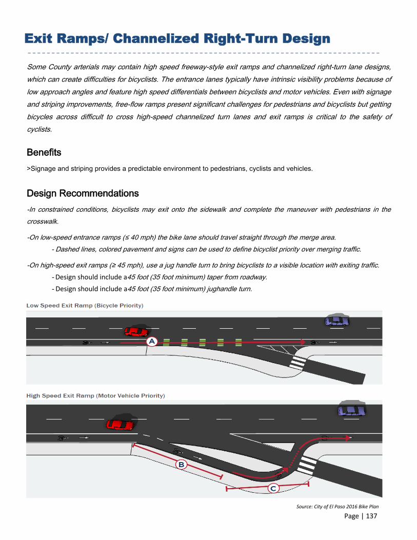
Some County arterials may contain high speed freeway-style exit ramps and channelized right-turn lane designs,
which can create difficulties for bicyclists. The entrance lanes typically have intrinsic visibility problems because of
low approach angles and feature high speed differentials between bicyclists and motor vehicles. Even with signage
and striping improvements, free-flow ramps present significant challenges for pedestrians and bicyclists but getting
bicycles across difficult to cross high-speed channelized turn lanes and exit ramps is critical to the safety of
cyclists.
Benefits
>Signage and striping provides a predictable environment to pedestrians, cyclists and vehicles.
Design Recommendations
-In constrained conditions, bicyclists may exit onto the sidewalk and complete the maneuver with pedestrians in the
crosswalk.
-On low-speed entrance ramps (≤ 40 mph) the bike lane should travel straight through the merge area.
- Dashed lines, colored pavement and signs can be used to define bicyclist priority over merging traffic.
-On high-speed exit ramps (≥ 45 mph), use a jug handle turn to bring bicyclists to a visible location with exiting traffic.
- Design should include a45 foot (35 foot minimum) taper from roadway.
- Design should include a45 foot (35 foot minimum) jughandle turn.
Exit Ramps/ Channelized Right-Turn Design
Source: City of El Paso 2016 Bike Plan

Page | 138
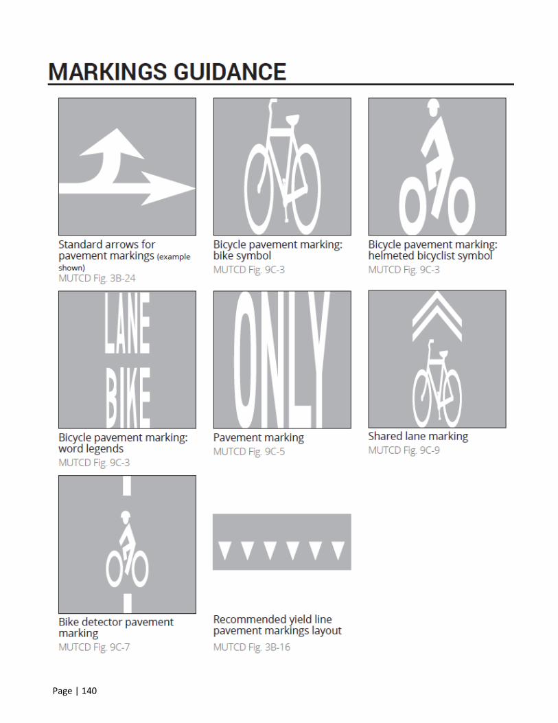
Signs and pavement markings supplement good design, create a predictable environment for motorists/ cyclists
and reinforce appropriate behavior for all roadway users. This section provides a summary of the most commonly
used signs and pavement markings related to separated bike lane installation.
Bicycle Facility Pavement Marking and Signage

Page | 139
Page | 140

Page | 141

Page | 142
Page | 143

Page | 144
This page intentionally left blank.