bicapped tetrahedral, trigonal prismatic, and octahedral ... · 2484 bicapped tetrahedral, trigonal...
TRANSCRIPT

2484
Bicapped Tetrahedral, Trigonal Prismatic, and Octahedral Alternatives in Main and Transition Group Six-Coordination
Roald Hoffmann,*la James M. Howell,lb and Angelo R. RossilC Contribution from the Departments of Chemistry, Cornell University, Ithaca, New York 14853, Brooklyn College, City University of New York. Brooklyn, New York, 1 1 21 0, and The University of Connecticut, Storrs, Connecticut 06268. Received June 30, 1975
Abstract: We examine theoretically the bicapped tetrahedron and trigonal prism as alternatives to the common octahedron for six-coordinate main and transition group compounds. The pronounced preference of six-coordinate sulfur for an octahe- dral geometry is traced by a molecular orbital analysis to a pair of nonbonding levels, whose higher energy in the nonoctahe- dral geometries is due to the molecular orbital equivalent of a ligand-ligand repulsion. For transition element complexes we draw a correlation diagram for the trigonal twist interrelating octahedral and trigonal prismatic extremes. A possible prefer- ence for the trigonal prism in systems with few d electrons is discussed, as well as a strategy for lowering the energy of the trigonal prism by symmetry-conditioned 7r bonding. The bicapped tetrahedron geometry for transition metal complexes can be stabilized by a substitution pattern ML4D2 where D is a good u donor and M is a d6 metal center.
In main and transition group six-coordinate compounds the octahedral geometry predominates. There is, however, a growing class of trigonal prismatic complexes and struc- tures intermediate between the octahedron and trigonal prism in coordination geometry.2a In six-coordinate tin and other group 4 element chemistry a wide range of coordina- tion geometries has been found.2b Some six-coordinate tran- sition metal dihydrides, of the general formula H2ML4, are highly distorted toward a bicapped t e t r a h e d r ~ n . ~ Presently there exists a unique non-hydride, Fe(C0)4(Si(CH3)3)2, which exhibits a similar d i ~ t o r t i o n . ~ W e also have the fasci- nating structural problem of xenon hexaf l~or ide .~ All these compounds, highly interesting in their own right, so far add up to but a small percentage of the myriad of complexes which assume a geometry close to octahedral.
Octahedral or near-octahedral six-coordinate molecules are generally stereochemically rigid. Perhaps this is more often assumed than proven, but we have the most direct demonstration in the isolation, under ambient conditions, of many cis-trans isomeric pairs of ML4XY complexes. In some molecules we also possess an N M R demonstration of the relative rigidity of MLsX species. A case in point is CsHsSFs, where the 19F spectrum shows an AB4 pattern up to 215 O C 6 Further stereochemical proofs or rigidity come from the optical activity of tris-chelate complexes M(L. - - L’)3. Studies of the kinetics of isomerization and racemiza- tion of such complexes have provided careful and indeed el- egant mechanistic contributions to the chemical literature.’ In most cases the obvious twist could be elim- inated, with bond rupture to a five-coordinate intermediate favored instead.I0.’ I More recently there have appeared several studies strongly supporting the operation of a twist mechanism or its permutational equivalent.I2
The term “permutational equivalent” signals a height- ened sensitivity, in recent times, to what the experiments are indeed telling us. A fully analyzed N M R spectrum gives us information on which sites are dynamically equivalent to others a t a given temperature. The full set of N ! permuta- tions of the N ligands of an MLN complex factors into a much smaller number of distinct basic permutational
or the somewhat differently defined rearrangement An optimal N M R experiment, including an
analysis of line shapes, may distinguish between some or all of the basic permutational sets.
There is some neat mathematics in the graphical, topo-
logical, or group theoretical analysis of rearrangement modes or basic permutational sets. However, the solution of the mathematical problem leaves the question of the physi- cal mechanism of a rearrangement still unsolved. A given permutation may be accomplished by a number of physical- ly distinct atomic motions. The permutational formalism is useful in suggesting what geometrical way-points might be examined in detail on the potential surface for the rear- rangement.
The purpose of this paper is not to examine the full sur- face for an ML6 complex. If the M-L distance is kept con- stant, that surface is nine-dimensional, and its complete survey certainly within the reach of modern semiempirical methods. However, we choose to begin with the known great preference for the octahedral geometry and to answer the question why SF6 or Cr(C0)6 prefer to be octahedral. As alternative structures to the octahedron 1, we will con- sider the trigonal prism 2, and the bicapped tetrahedron 3. An understanding of the electronic structure of 1, 2, and 3 will provide us with the strategy for shifting, if possible, the conformational balance from 1.
1 2 3
Previous Discussions of ML6 Geometries An interesting early discussion of why octahedral coordi-
nation is preferred to trigonal prismatic was given by Hult- gren.I8 Within the valence bond framework of constructing a t the metal hybrids which maximize overlap with ligand orbitals, he concluded that a trigonal prism configuration would have greater energy per bond, but the octahedron would have smaller repulsive forces between the surround- ing atoms.
Thus in the above discussion ligand-ligand repulsion was already introduced. In Gillespie’s scheme of the determi- nants of molecular geometryIga the emphasis is on the re- pulsion of bond electron pairs (and lone pairs where neces- sary). For SF6 and do and dIo systems the problem of the best arrangement of six localized electron pairs is isomorph- ic to the ligand-ligand repulsion problem. The explicit form of the interaction potential is left unspecified, but in the
Journal of the American Chemical Society / 98:9 / April 28, 1976

2485
specific case of six points this is immaterial, for the octahe- dron is preferred for all repulsive potentials. Note that the nonoctahedral geometry of XeF6 is correctly predicted by the Gillespie model, by invoking a stereochemically active lone pair.Igb This molecule has been the subject of a num- ber of theoretical studies, the geometrically most detailed of which is by Wang and Lohr.20
For transition metal complexes the question of depar- tures from octahedral geometry has received considerable attention, within the framework of crystal and ligand field theory and the application of first- and second-order Jahn- Teller arguments.21q22
Fay and Piper, in their pioneering study of the racemiza- tion and isomerization of tris-chelate complexes, calculated crystal field stabilization energies for d60h and D3h geome- t r ies9 They reported that surprisingly the stabilization en- ergy was greater for the trigonal prismatic coordination. This in turn implied that the observed preference for octa- hedral coordination was set by the ligand-ligand repulsions, which, as we mentioned above, greatly favor the octahe- dron. More recent ligand-field and angular overlap model studies have given us a good picture of the way that the en- ergy levels vary along a trigonal twist reaction coordin- ate.23-27 The relationship of the bicapped tetrahedron has been investigated in but one of these studies, that of Bur- dett.27
SRs and Six-Coordinate do and dl0 Systems We have found it useful to separate the analysis of six-
coordinate main group compounds, such as SF6, SiF62-, PFs-, and their derivatives, from six-coordinate transition metal complexes. Model calculations of ab initio and ex- tended Huckel (EH) types were carried out on SH6 in octa- hedral and trigonal prismatic geometries. Details are given in the Appendix. An S C F optimization of the S H distance in octahedral SH6 yielded a value of 1.40 A,28 which was consistently used throughout our calculations.
There are two trigonal prism geometries that we consid- ered, one obtained by .a simple rotation of one triangular face of an octahedron by 60°, the other an optimized geom- etry subject to a D 3 h constraint and the constant S H dis- tance mentioned above. If we define the metal to ligand dis- tance as I , the ligand-ligand distance within one triangle as s, and the distance between the triangular planes as h31 (see 4), then in the simply twisted trigonal prism h = -\/;r75 1 =
1.617 A and s = v’2 I = 1.900 A. In the optimum energy prism h = 1.856 A and s = 1.816 A. Unless otherwise stat- ed, a reference to a trigonal prismatic SH6 will refer to this optimum geometry.
The octahedral geometry was preferred to the trigonal prism by 4.2 eV in the S C F calculation with d orbitals ab- sent from the basis set, 4.4 eV in an S C F calculation with 3d orbitals included, 2.9 eV for EH without 3d orbitals, and 1.8 eV for E H with 3d orbitals low-lying and contracted for optimum interaction. The wave functions for both oh and D3h geometries are much the same in the S C F and EH cal- culations.
The problem of d orbital participation in “octet expand- ed” silicon, phosphorus, and sulfur structures is an old
Our pragmatic view is that since it is difficult to de- lineate the extent of participation of 3d orbitals, and unpro- ductive to argue about it, it is best to consider the extremes
of no participation and strong mixing. We intend to try to understand any phenomenon in the absence of d orbital par- ticipation, then to examine how d orbital mixing changes the situation.
In both the EH and SCF calculations SH6 has a substan- tial preference for the octahedral geometry even in the ab- sence of 3d orbitals in the sulfur basis set. Let us first trace that effect. Figure 1 shows a standard interaction diagram for o h and D3h geometries of SH6.
The imprtant point to note is that in the absence of 3d or- bital mixing there is a nonbonding pair of orbitals which, in either oh or D3h symmetry, is entirely localized on the li- gands:This is the eg set in oh, err in D3h. Just counting metal-ligand interaction we would not find any difference between the two geometries-each would have four strong- ly bonding levels and two nonbonding ones. When the cal- culations are actually examined, they show that the eg and err levels are not a t the same energy. For instance in the EH calculation without 3d eg is at -1 1.24 eV, err at -10.47 eV. The barrier to the trigonal twist interconverting the oh and D3h geometries is predominantly due to these e levels.
Why is there such a large difference in energy between the eg and err levels? That energy differential is the result of ligand-ligand interaction and the geometrical constraints of the trigonal prismatic coordination. The octahedral eg levels are entirely determined by symmetry. They are shown in 5 and 6. In 7 and 8 the same orbitals are shown in a different
- 1
111 Ill
view, one that has the vertical axis coincide with a threefold rotation axis of the octahedron. This coordinate system is natural for intercomparing the octahedron and the trigonal prism, for the motion relating them leaves the threefold axis intact. The err levels of the trigonal prism are shown in 9 and 10. It is obvious that the eg and err levels have really the same shape-they both are composed from the out-of-phase combination of symmetry-adapted three levels of each triple of hydrogens. The e” and eg levels are antibonding within each triple of hydrogens and antibonding across to the other triple. The effect is a net one-that is there are bonding contributions, visible especially in 8 and 10, but they are outweighed by the antibonding overlaps. Since the two err or eg components are equivalent, let us concentrate on 7 and 9.
The err component 9 is a t considerably higher energy than the eg level which is its counterpart, 7. The reasons for this are geometrical. Referring back to structure 4 and the
Hoffmann. Howell, Rossi / Geometry in Main and Transition Group Six-Coordination

2486
D3h Oh
e‘ ,$ C d
- d 2 a , + a F + b , + b 2 -
s - aI
H S
3c
S H6 S S Figure 1. Interaction diagram for octahedral (left) and trigonal pris- Figure 2. Interaction diagram for a bicapped tetrahedron geometry of matic (right) SH6. SH6.
associated definitions of I , s, and h, consider first the simple rigid rotation of one triangle of an octahedron relative to the other by 60°. In the tri onal prism that results the inter- plane distance h = * 4/31 is maintained and in fact be- comes the shortest ligand-ligand contact, shorter than the octahedral s = 4 2 1. Since the corresponding ligand orbit- als are required to be out-of-phase (see 7 and 9) , there is more antibonding in the trigonal prism orbital.
One could try to escape this situation by not imposing the constraint that the h be constant during the trigonal twist. But for a constant 1 this can only be achieved by making s less than it is in the octahedro. In particular if we make h = d2 I, then s = 1, to be compared to d2 1 in the octa- hedron. Since the e’I orbital is also net antibonding within a triangle, such a geometry will also be destabilized relative to the octahedron. To summarize: in any D3h geometry the e” orbital will be more antibonding, less stable than the cor- responding eg orbital of an octahedron with the same M-L distance.33
It should be noted that a t this stage the M O rationaliza- tion of the preferred octahedral geometry has come to the orbital equivalent of a ligand-ligand repulsion. This is not unexpected, but it is interesting to note those other cases where a connection between an orbital theory and an elec- trostatic or steric explanation can be made.34 Another inter- esting connection to be made is between the present work and the origins of the barrier to internal rotation in ethane. In a one-electron M O analysis the ethane barrier is traced to the e levels of two interacting methyl groups.35 These combine to an eg and e,, set in the staggered conformation, e” and e’ in the eclipsed form. The greater ligand-ligand in- teraction, net repulsive, in the eclipsed geometry is the de- termining factor in both the ethane barrier and octahedral vs. trigonal prismatic SH6. The slight lengthening of CH bonds that is observed in calculations on eclipsed ethane conformations is matched by an analogous effect in our SH6 calculations. If the bond lengths in the trigonal prism are independently optimized, they come out 0.05 A longer than the octahedral value with a basis set that excludes 3d orbitals, 0.02 A longer if 3d orbitals are included.
We turn briefly to an analysis of an alternate ML6 struc- ture, the bicapped tetrahedron 3. The idealized geometry places the six hydrogens a t the corners of a cube. An inter- action diagram is shown in Figure 2. Once again we find four bonding levels and two nonbonding ones, when 3d or- bitals are omitted. This recurrent pattern should be no sur- prise, for it is related to the united atom limit of this mole- cule or, alternatively, to a particle in a spherical box. Either
way we would expect a low-lying nodeless orbital, followed by three orbitals with one angular node. Only in o h are these three orbitals degenerate. The breaking of the symme- try by departures from o h does not change the essential pattern, which is set by the spherical pseudosymmetry of the problem.
The nonbonding orbitals of the bicapped tetrahedron have the following shape:
I n a bicapped tetrahedron it need not be that all M L dis- tances are equal. For instance it could be that the two cap- ping atoms are further away from the central atom. In the absence of any relevant structural information, if we as- sume that all M L distances are equal, and the same as in the octahedron, the antibonding character of the al and bl orbitals shown above is considerably greater than in the oc- tahedron. In an extended Hiickel calculation the al level is a t -8.84 eV, bl a t -10.54 eV. The bicapped tetrahedron calculated by EH is 6.1 eV above the octahedron without 3d orbitals, 3.4 eV with 3d’s. The destabilization is easily traced to the short contacts of a 1.
We proceed to an analysis of how 3d orbital participation affects the relative energies of the oh and D3h forms. Fig- ure 1 is to be referred to a t this point. The 3d levels trans- form as the irreducible representations eg and t2g in oh. One of these, eg, matches the symmetry of the crucial li- gand orbital. In D3h the 3d orbital set also has a counter- part to the ligand orbital e”. Counting interactions alone, there would seem to be no additional differentiation be- tween the two geometrical extremes. But this is not quite true. In the octahedron there is a perfect match between the 3d eg set, z2 and x2 - y 2 , and the symmetry-adapted ligand set. This is shown in 11 and 12.36 In the trigonal prism the overlap of the e” ligand orbitals with xz and yz , 13 and 14, is somewhat smaller. 13 shows especially well how this over- lap is partially 6 in character. Thus judging by overlap alone one would expect the difference in energy between oh and D3h to increase, since there is more efficient overlap with 3d functions and therefore stabilization of the occu- pied orbitals in the octahedral geometry. This is not reflect-
Journal of the American Chemical Society / 98:9 / April 28, 1976

2487
11
13
x2-y*
XZ
12
z 2
14
Y Z
ed in the extended Hiickel calculations. The reason for the discrepancy is that we cannot consider the overlap alone, but must worry about the energy denominator in the stan- dard perturbaion expression for the interaction energy
IHijl Ei - Ej
AE =
Just because the nonbonding e” levels are significantly higher than the eg the former will interact better with a low- lying set of 3d orbitals. With the particular choice of 3d pa- rameters used in our calculations the energy factor domi- nates. A similar effect takes place in the bicapped tetrahe- dron. The energy lowerings calculated for the trigonal prism and bicapped tetrahedron when 3d orbitals are in- cluded are to be viewed as extrema of 3d interaction, with realistic molecular systems somewhere in between.
In summary the preference for the octahedral geometry of SR6 compounds is traced to nonbonding levels, destabi- lized by ligand-ligand overlap, and more so in the trigonal prism.
Six-Coordinate Transition Metal Complexes Extended Hiickel calculations on the prototype Cr(C0)6
gave the octahedron an energy 1.3 eV lower than that for an idealized trigonal prism. To separate the effects of n and P bonding we also performed a calculation on a model CrH66-. The parameters for both calculations are described in the Appendix. The model hydride favored the octahedron by 2.9 eV.
The level pattern in both models is qualitatively that shown below. We illustrate only the levels which are derived
i A A A v Oh D3 D3h
=\
15
7 - - - 1
! _ I \
d
6L ML6 M Figure 3. Interaction diagram for a trigonal prismatic transition metal complex.
from the metal 3d orbitals, even though the extent of mix- ing with ligand orbitals is often so great that such an identi- fication is difficult to make. In the carbonyl case several carbonyl T* levels moreover come below the eg-e” set indi- cated here.
The octahedral splitting of t2g below eg is most familiar. In the absence of T bonding ligands the set is pure metal 3d. If we imagine the trigonal twist proceeding, the triple degeneracy is split, with one level, the a,’, z2, little affected by the motion. In the absence of A bonding ligands, as in the model chromium hydride, the trigonal twist indeed leaves the t2g component which becomes al’ in D3h totally unaf- fected. This is because the twisting hydrogens are in the nodal surface of the z2 orbital. With carbonyl substituents the a]’ component of moves to slightly lower energy in 0 3 and D3h, but the effect is small. The other t2g compo- nent, e in D3, becoming e’ in D3h. is destabilized relative to the octahedron. It is composed on the metal of xy and x2 - y2, with some admixture of x and y . The easiest way to see the source of the destabilization of e’ is to set up the interac- tion diagram for the trigonal prism, which is done in Figure 3. The important point is that the set of ligand orbitals con- tains an e’ representative. This is the in-phase combination of the symmetry-adapted triangle e functions, analogous to the out-of-phase combination shown in 9 and 10. The over- lap of these e’ orbitals with metal xy and x2 - y2 is not good, but is sufficient to cause some destabilization.
There is nothing novel in our analysis of the level trends shown in 15. The ordering of D3h levels is the same as that obtained previously by other workers.37 The way that the levels vary with the trigonal twist has been analyzed by T ~ m l i n s o n , ~ ~ W e n t ~ o r t h , ~ ~ Huisman et al.,25 and Larsen et a1.,26 and our results agree with these investigators.
Level scheme 15 implies that the preference for the octa- hedron will be maximal for the low spin d6 case. At either extreme of the transition series the trigonal prismatic geom- etry is of approximately equal energy to the octahedron. In fact our extended Hiickel calculation for Cr(C0)6, if used for an arbitrary number of electrons, gives a lower energy for D3h over Oh for do-d4 and dlO. No doubt this is an arti- fact of using metal parameters outside the range of their va- lidity, nevertheless we must face an apparent paradox. While the sL6 system very clearly favored octahedral coor- dination, the extremes of the transition metal series, do and d’O systems, which should give a similar result, do not ap- pear to do so. The reason for this behavior may be found in a comparison of Figure 1 and Figure 3. As long as the d or-
Hoffmann, Howell, Rossi / Geometry in Main and Transition Group Six-Coordination

2488
bitals were high in energy (SHs, Figure l), and the bonding was set by s and p orbitals, both the octahedron and the tri- gonal prism had four bonding levels and two nonbonding, or more correctly said, slightly antibonding levels. The balance in favor of the octahedron was set by those nonbonding lev- els. The situation of Figure 3, where d orbitals are low, and s and p relatively high, is quite different. In the high sym- metry of the octahedron only the eg d orbital component can participate in cr bonding. In the trigonal prism the sym- metry allows all d orbitals to participate in cr bonding. Be- cause of their pseudosymmetry, they do not do so very ef- fectively, but nevertheless there is a better cr bonding situa- tion in the trigonal prism geometry when the metal 3d or- bitals are a t low energy.
It is clear that the geometry of a particular complex is not only governed by the d orbital patterns. The various structural parameters of the coordination sphere-the size of the metal ion, the bite angle of the ligands, their mutual steric interference-all these factors obviously will influ- ence the observed equilibrium geometries. One cannot hope from model calculations to extrapolate directly to sterically encumbered bidentate ligands, but all we can do here is to trace as completely as possible the electronic effects pre- dicted by our one-electron model. The next paragraphs re- view some of the experimental evidence pertinent to our conclusions: (1) low numbers of d electrons, especially do- d2, are the optimum situation for trigonal prismatic coordi- nation; (2) for a given d electron configuration the lower the energy of the metal d orbitals, the stronger the metal- ligand bonding in the trigonal prism; (3) occupation of the e’ levels will add an energy increment favoring the octahe- dron, while electrons in e” restore the balance toward a tri- gonal prism.
The first trigonal prismatic complex proven as such was Re(S2C2Ph2)3.38a It was followed by a number of similar complexes with sulfur or selenium chelating ligands.2a The dithiolate ligand in its classical formulation is a dinegative ion. From this point of view these are d ’ Re(V1) complexes. The actual charge distribution in these complexes is far from that, as was recognized by Eisenberg and Gray in their molecular orbital calculations on a model for the tri- gonal prismatic Any configurational assign- ment depends on identifying highly delocalized orbitals as “belonging” to either ligands or metal, and is bound to be artificial. Nevertheless, to view these complexes as d’ has some heuristic value, for it makes a consistent picture with the implications of level diagram 15. I t might be noted that V(S2C2(CN)2)32-, which might be counted as a d’ com- plex, and M o ( S ~ C ~ ( C N ) ~ ) ~ ~ - and W ( S Z C ~ ( C N ) ~ ) ~ ~ - , both d2, possess solid-state structures intermediate between the trigonal prism and octahedron.38b
The role of the energy of the 3d orbitals has been noted by Bennett, Cowie, Martin, and T a k a t ~ , ~ * ~ who determined the structures of the isoelectronic tris(benzenedithio1ato) complexes Mo(S&,jH4)3, Nb(S2C6H4)3-, and Zr(S2CsH4)32-. The Mo complex is trigonal prismatic, the niobium analogue close to that geometry, while the Zr com- plex is closer to octahedral. The M-S distances increase along the series. Several other factors might be responsible for the trend, and were considered by the authors, but one determinant could be an increase in the d orbital energy as one moves from Mo to Zr.
That it is not unrealistic to imagine that a trigonal pris- matic coordination geometry may have an advantage over an octahedral one for transition metal centers with few d electrons (do-d2) becomes clearer if one leaves the domain of discrete molecules and considers extended solid-state structures. There is a large class of layered structures, disul- fides and diselenides of Nb, Ta, Mo, and W, in which the
metal atoms lie in trigonal prismatic environment^.^'^ Simi- lar coordination is found for metal atoms intercalated in the above structures. In some cases a temperature dependent equilibrium between trigonal prismatic and octahedral coordination is found, with the latter of higher energy.39 The reader is referred to the interesting and comprehensive account of bonding in these structures by Huisman, De Jonge, Haas, and Jellinek.25
A number of tris complexes with geometries intermediate between trigonal prism (twist angle between the two trian- gles of 0’) and octahedron (twist angle 60’) are k n o ~ n . ~ ~ . ~ ’ An interesting case in point is a comparison of two iron(II1) complexes.40 One, tris(0-ethy1xanthato)iron is a low spin complex, with a configuration in the octahedral limit pre- sumably corresponding to t2g5. The other, tris(N,N-di-n- butyldithiocarbamato)iron, is a high spin complex corre- sponding to the limiting configuration t2g3e,2. The high spin complex has a structure with a twist angle of 32’, the low spin complex 41’. Both are intermediate in geometry, but it is consistent with our results that the low spin complex is closer to the octahedral limit. Other examples are discussed by W e n t ~ o r t h ~ ~ and Larsen et a1.26
In the several mechanistic studies which have supported a twist mechanism, a correlation was sought between ease of rearrangement and a ground state distortion from octahe- dral toward trigonal prismatic c~ord ina t ion .~’ Sometimes a case for such a correlation could be made, but there is one clear instance, that of the Co(II1) complexes, where the correlation breaks down. These rearrange easily and yet are close to the octahedron (twist angle in one structure of 55O) in their ground state geometry. Another interesting ques- tion raised by the mechanistic studies is that of the effect of the chelating ligands. Acetylacetonates rearrange much slower (and apparently by a bond rupture mechanism) than t r o p ~ l o n a t e s . ~ ~ I t is not a t all certain that x bonding effects contribute to the two observations quoted above. But it may be useful to analyze the role of x acceptors in favoring one or the other conformation within our bonding scheme.
The 12 orbitals of six cylindrically symmetrical x accep- tor ligands transform as tl, + t2g + t l , + t2, in o h , al’ + a2’ + a]’’ + a2” 4- 2e’ + 2e” in D3h. For hypothetical six- coordinate d7-d10 structures such an acceptor set could pro- duce a stabilization of the trigonal prismatic geometry. This is because the metal eg has no acceptor orbitals to interact with in the octahedron, but metal e” in the trigonal prism finds a match in the acceptor set.
Now let us consider a set of three chelate ligands, as shown in 16 below. Each ligand will have a a-system, and in particular let us assume it has a low-lying acceptor orbital. The a system can be thought of as a ribbon, and the accep- tor orbital can be p type or d type, respectively symmetric, 17, or antisymmetric, 18, with respect to a (pseudo) mirror plane bisecting the ribbon.43 If the individual ribbon accep-
n
16 17 18
tor orbital is locally symmetric, the three ribbon acceptor orbitals will transform as a2 + e in D3, a2’ + e’ in D3h. If the ribbon is antisymmetric, we will have al + e in D3, a]’’ + e” in D3h.44 In a d6 system, if we wish to stabilize the tri- gonal prism, we must lower the energy of the e’ orbital. Only a symmetric ribbon can accomplish this.
In an acetylacetonate ligand, 19, we have a 6 a electron system extending over five atoms. The lowest unfilled x or-
Journal of the American Chemical Society / 98:9 / April 28, 1976
2489
bital is antisymmetric, of type 18, and thus ineffective a t stabilizing the trigonal prism. In a tropolonate ligand, 20,
0
0 19 20
an extended Hiickel calculation yields a pair of acceptor or- bitals, one symmetric, one antisymmetric, with the symmet- ric one slightly lower. We were led to examine the lower lying unfilled a * molecular orbitals of a series of real or po- tential bidentate ligands, 21-32. In these structures X = 0, S, or N H and Y = N.45 For ligand systems 25, 29, and 32 the lowest unfilled orbital is antisymmetric, implying no tendency to stabilize a trigonal prismatic geometry. The other ligands have a symmetric or pseudo-symmetric LUMO, which according to this analysis should help in sta- bilizing a trigonal prism. In 22, 23, and 24 the symmetric
22 23
25 26
27 28 29
9-Donor substituents at C4 would raise the energy of this orbital, acceptors would lower it.
It should be noted that the angular overlap calculations of Larsen, LaMar, Wagner, Parks, and Holm26 probed the significance of a-(anti)bonding. Their analysis, by taking the same sign for each ligand a energy term, essentially as- sumes a symmetric ribbon of type 18. Within that assump- tion the effect of x-bonding on the energy of the e’ level ap- pears to be small-approximately as much stabilization of the e‘ occurs in the D3h as the oh geometry. These results would indicate that a bonding effects are of little impor- tance in the energetics of the twisting process.
The Bicapped Tetrahedron Geometry for Transition Metal Complexes
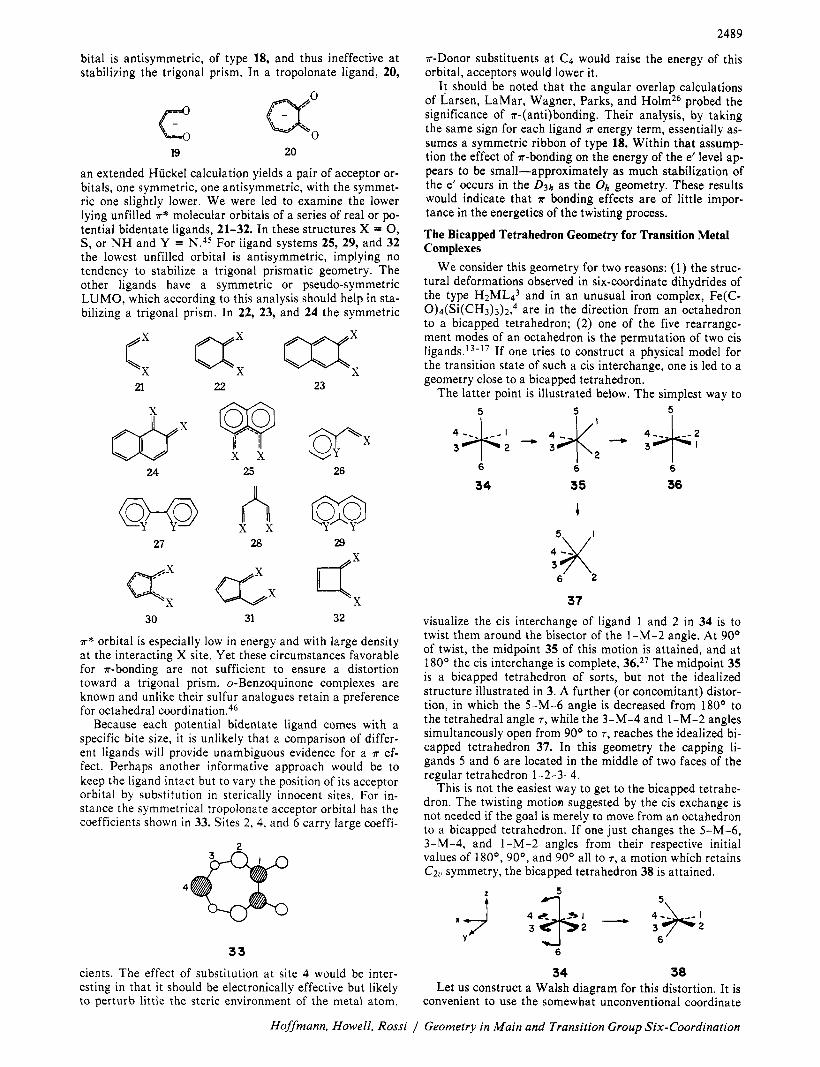
We consider this geometry for two reasons: (1) the struc- tural deformations observed in six-coordinate dihydrides of the type H2MLd3 and in an unusual iron complex, Fe(C- 0)4(Si(CH3)3)2,4 are in the direction from an octahedron to a bicapped tetrahedron; (2) one of the five rearrange- ment modes of an octahedron is the permutation of two cis ligand^.'^-'^ If one tries to construct a physical model for the transition state of such a cis interchange, one is led to a geometry close to a bicapped tetrahedron.
The latter point is illustrated below. The simplest way to 5 5 5
30 31 32
a * orbital is especially low in energy and with large density at the interacting X site. Yet these circumstances favorable for a-bonding are not sufficient to ensure a distortion toward a trigonal prism. o-Benzoquinone complexes are known and unlike their sulfur analogues retain a preference for octahedral c ~ o r d i n a t i o n . ~ ~
Because each potential bidentate ligand comes with a specific bite size, i t is unlikely that a comparison of differ- ent ligands will provide unambiguous evidence for a a ef- fect. Perhaps another informative approach would be to keep the ligand intact but to vary the position of its acceptor orbital by substitution in sterically innocent sites. For in- stance the symmetrical tropolonate acceptor orbital has the coefficients shown in 33. Sites 2, 4, and 6 carry large coeffi-
2
t
6 6 6
34 35 36
33 cients. The effect of substitution at site 4 would be inter- esting in that it should be electronically effective but likely to perturb little the steric environment of the metal atom.
I
6 2
37 visualize the cis interchange of ligand 1 and 2 in 34 is to twist them around the bisector of the 1-M-2 angle. At 90° of twist, the midpoint 35 of this motion is attained, and at 180° the cis interchange is complete, 36.27 The midpoint 35 is a bicapped tetrahedron of sorts, but not the idealized structure illustrated in 3. A further (or concomitant) distor- tion, in which the 5-M-6 angle is decreased from 180° to the tetrahedral angle T , while the 3-M-4 and 1-M-2 angles simultaneously open from 90’ to T, reaches the idealized bi- capped tetrahedron 37. In this geometry the capping li- gands 5 and 6 are located in the middle of two faces of the regular tetrahedron 1-2-3-4.
This is not the easiest way to get to the bicapped tetrahe- dron. The twisting motion suggested by the cis exchange is not needed if the goal is merely to move from an octahedron to a bicapped tetrahedron. If one just changes the 5-M-6, 3-M-4, and 1-M-2 angles from their respective initial values of 180°, 90°, and 90’ all to T , a motion which retains CzU symmetry, the bicapped tetrahedron 38 is attained.
5\
6
34 38 Let us construct a Walsh diagram for this distortion. It is
convenient to use the somewhat unconventional coordinate
Hoffmann, Howell, Rossi / Geometry in Main and Transition Group Six-Coordination

2490
-3 L-----l
“t -9
- I2
0 0 0.2 0 4 0.6 06 I O Bending Coordinate 8
Figure 4. The behavior of the frontier orbitals of CrH& as a function of distortion from the octahedron to the bicapped tetrahedron. Progress of the reaction from 34 to 38 is measured by a bending coordinate, 0. At a given 0 the 5-M-6 angle is given (in degrees) by 180 - (180 - T)e and the 1-M-2 and 3-M-4 angles are both 90 + (T - 90)e. Thus 0 = 0 is the octahedron, and 0 = 1 is the idealized bicapped tetrahedron. T is the tetrahedral angle. The two a ] levels are labeled according to their character in the two extreme geometries.
system to the left of 34, with x and y axes located between the ligands. In this coordinate system the octahedral t2g set contains xz, yz, and x2 - y2 , and the eg orbitals are z2 and xy. It is obvious that the motion illustrated in 34 will great- ly stabilize the z2 orbital by moving the axial ligands 5 and 6 off their sites of maximal u antibonding. xy will similarly be stabilized slightly. In the t2g set yz is unaffected, x 2 - y 2 somewhat destabilized, and xz strongly destabilized by u antibonding with ligands 5 and 6. These qualitative conclu- sions are supported by the computed energy levels for a model CrH66- system in which the ligands bear only u type orbitals (Figure 4). Note that what were the z2 and x 2 - y 2 orbitals in o h mix strongly along the reaction coordinate, since they are both of a1 symmetry in C2”. In the bicapped tetrahedron the mixing is precisely such as to form an “x2” orbital, exactly nonbonding because the idealized geometry places all six ligands in its nodal surfaces. A similar distor- tion was studied for Cr(C0)6, with qualitatively similar re- sults.
The orbital ordering of the bicapped tetrahedron is equally well derived by beginning with a tetrahedron and bringing in the two capping ligands. This is illustrated in 39. Please note for further reference that, if the two incoming
z2-xyy2 =$/ \\ z x z -r- \\
39 yz--\y L’
ligands are normal bases, then 39 implies that the capping will be net destabilizing for a dl0 system. This is because both the ligand orbitals and the metal functions they inter- act with are occupied.47 If the ligand orbitals were empty, the interaction diagram would appear different. Placing the L orbitals above the tetrahedron t2 set would produce a net stabilization of the d10 system through a lowering in energy of the xy and z 2 - y 2 orbitals. Structures such as HNiL4+, HCo(C0)4, and H2Fe(C0)4 can be viewed in this way, as protonated d’O ML4 systems.
It is clear from Figure 4 that a d6 system gives the octa- hedron the biggest advantage. For the model CrH66- the octahedral geometry is preferred to the bicapped tetrahe- dron by 3.5 eV, for Cr(C0)6 by 2.7 eV. Both these energy increments are somewhat greater than those of trigonal prismatic coordination. Can the energy of the bicapped tet- rahedron nevertheless be improved? Two strategies suggest themselves, one based on the differential charge distribution in the bicapped tetrahedron, the other on modifying the fill- ing of the levels in Figure 4.
The charge distribution in the model CrHb6- is shown in 40. A similar pattern is obtained for Cr(C0)6, with the cap-
-0.4 2
D=u-Donor
0 A A = u-Acceptor
40 41
ping ligands 3 and 4 relatively positive and the sterically freer ligands 1 and 2 most negative. This suggests that more electronegative substituents ( Q acceptors) would prefer the latter sites and more electropositive substituents (u donors) would enter the former sites. The substituent pattern im- plied is that of 41. Model calculations support the conclu- sion that such a pattern, or any piece thereof, would lower the energy of a bicapped tetrahedron.
The other approach for stabilizing a bicapped tetrahe- dron focuses on the Walsh diagram of Figure 4. Any elec- tronic configuration which would deplete the population of the xz orbital and increase the population of z2 - y 2 is going to favor distortion toward the bicapped tetrahedron. Such configurations are achieved in the lower excited states of an octahedron, and the bicapped tetrahedron has in fact been considered as a potential transition state for photo- chemical isomerization of six-coordinate complexes by Bur- dett.27
Another way to achieve population of the z2 - y 2 orbital is to make two of the six ligands such good donors that they effectively transfer their lone pair electrons to the metal, thereby changing it from a d6 toward a d l* configuration. The way in which this can happen is best explained by com- paring the left side of Figure 5, an inteiaction diagram for a normal octahedral complex with all six ligands identical with the right side, where two trans ligands are made excep- tionally good u donors.
The two axial ligands L’ form symmetry adapted sym- metric and antisymmetric combinations which interact with metal z 2 (primarily, also with s ) and z . The bonding combi- nations are shown in 42 and 43. In the normal octahedron
42 43
Journal of the American Chemical Society / 98:9 / April 28, 1976

249 1
L
Figure 5. Interaction diagram for a normal octahedral complex (left) and for one in which two trans ligands, L’, are much better u donors than the other four ligands. The mixing coefficient X is to be assumed less than 1.
with all six ligands of identical a-donor ability the bonding combinations are mainly localized on the ligands, and less so on the metal, Le., CL > CM in x = CLL + CMd. This is the situation a t the left of Figure 5. Now suppose the two axial ligands, L’, become very good a donors, rising in energy above the metal d orbitals. The coefficient ratio in the bonding combinations changes, now CM > CL. The two bonding combinations leave the octahedral grouping of six highly bonding low-lying levels and move up. The combina- tion 43 moves up rapidly, since one of its components is anyway a high-lying metal p. The situation depicted a t right in Figure 5 has that bonding combination between the ‘‘t2g” set and x 2 - y 2 . Making L’ a still better donor might even cause a crossing of x 2 - y 2 and 43, with a switchover of the electron pair to the metal. At the same time the bonding combination 42 is becoming increasingly localized on the metal, looking more and more like z2. In the extreme case we have changed a d6 to a d10 complex.
An alternative way to see the change in electron configu- ration as a function of the a-donor strength of the ligands is to think of tlhe specific case of FeL4H2. We normally think of the hydrogen as a hydride, H-, and assign to the iron the formal oxidation state 11, corresponding to d6. But a t the other limit, were we to view the hydrogen as protonic, H+, we would have a dl0 transition metal center. The truth is somewhere in-between those two extremes. In general, in the complex ML~L’z, we can achieve a range of d electron population on the metal by varying the relative a donor strength of the ligands.
It is then possible to make a connection to an earlier dis- cussion of ML,L’ and ML,,L‘* g e ~ m e t r i e s . ~ ~ If L’ is a much better a donor than L, then the equilibrium geome- tries of these molecules will be set by the geometrical pref- erences of the MLn2- and MLn4- fragments, respectively.
In concluding our initial discussion of the distortion to a bicapped tetrahedron, we must emphasize that our preoccu- pation with an electronic explanation for this deformation should not be interpreted as an argument for the unimpor- tance of steric factors. These obviously matter. Our desire to point to the unusual Fe(C0)4(Si(CH3)3)2 structure as an example of an electronically controlled deformation must also be tempered by the knowledge that compounds which are electronically not in an obvious way dissimilar, Fe(C- O ) ~ ( C F Z C H F ~ ) ~ ~ ~ and R ~ ( C 0 ) 4 ( G e C 1 3 ) 2 , ~ ~ possess struc- tures close to octahedral.s’ A secondary reason for pointing to the bicapped tetrahedron is simply to get people used to thinking about still another six-coordinate geometry. Even in the class of tris-chelate structures, which might have
Table 1. Extended Hiickel Parameters
Exponentsa
Orbital Hii (1 (2
Cr 3d -11.67 5.15 1.70
Fe 3d -13.50 5.35 1.80 (0.51392) (0.69290)
(0.536591 (0.66779) Cr 4s -9.75 0.970 Cr 4p -5.89 0.970 Fe 4s -10.56 1.575 Fe 4p -6.19 0.975 c 2s -21.40 1.625
-11.40 1.625 -32.30 2.275 -14.80 2.275
‘0 2 0 2D
-20.00 -11.00
-8.00
2.122 1.827 1.500
H Is -13.60 1.300
Two Slater exponents are listed for the 3d functions. Each is fol- lowed in parentheses by the coefficient in the double (expansion.
seemed ideally predisposed to occupy some point on the continuum connecting octahedral and trigonal prismatic geometries, there are a number of puzzling departures from D3 ~ y m m e t r y . ~ ~ - ~ ~ Perhaps one should examine how far these structures are from a bicapped tetrahedron.
Acknowledgment. We are grateful to W. A. G. Graham for communicating some structural information prior to publication, and to D. M. P. Mingos for playing an inter- esting role in this communication process. We also thank J. K. Burdett, M. Elian, R. C Fay, R. H. Holm, and J. Takats for some discussions on this problem and C. C. Levin for some assistance in the calculations. The SH.5 octahedron vs. trigonal prism problem was posed for several years running on a Cornell graduate course final and was successfully solved by the great majority of students in the course. Our work was generously supported by the National Science Foundation and the Advanced Research Projects Agency through the Materials Science Center a t Cornell Universi- ty. J.M.H. acknowledges a grant of computer time from the Central Computer Facility of C.U.N.Y.
Appendix The a b initio calculations on SH6 without 3d orbitals
were performed with the GAUSSIAN 70 program,” employ- ing an STO-3G basis for both H and S atoms.56 For SH6 calculations with 3d orbitals we used IBMOL-5 with STO- 3G type basis.s7
All other calculations on SH6 and those on CrH&, Cr(C0)6, and Fe(C0)4H2 were carried out by the extended Hiickel method.5s The parameters are summarized in Table I.
For CrHG6- a Cr-H distance of 1.60 8, was assumed. In Cr(C0)6 we took Cr-C, 1.80 A, and c - 0 , 1.13 8,. In Fe(C0)dHz we used Fe-C, 1.83 A, Fe-H, 1.58 A, and C-0 , 1.13 A. The SH distances are discussed in the text. With 3d orbitals in the basis the SH distance optimized a t 1.34 8, in the octahedron, 1.36 8, in the optimum trigonal prism.
References and Notes (1) (a) Cornell University; (b) Brooklyn College: (c) The University of Con-
necticut. (2) (a) Two reviews with leading references are R. Eisenberg. Prog. Inorg.
Chem., 12, 295 (1970); R . A. D. Wentworth, Coord. Chem. Rev., 9, 171 (1972). (b) See for instance E. 0. Schlemper, lnorg. Chem., 6, 2012 (1967): T. Kimura, N. Yasuoka, N. Kasai, and M. Kakudo, Bull. Chem. SOC. Jpn., 45, 1649 (1972); P. H. Bird, A. R. Fraser. and C. F. Lau, Inorg. Chem., 12, 1322 (1973). The structural chemistry of tin is re- viewed by B. v. K. Ho and J. J. Zuckerman, J. Organornet. Chem., 49, 1 (1973).
Hoffmann, Howell, Rossi / Geometry in Main and Transition Group Six-Coordination

2492
(3) See the review by B. A. Frenz and J. lbers in "Transition Metal Hy- drides", E. L. Muettertles. Ed., Marcel Dekker, New York, N.Y., 1971, p 33; L. J. Guggenberger, D. D. Titus, M. T. Flood, R. E. Marsh, A. A. Orio, and H. B. Gray, J. Am. Chem. Soc., 04, 1135 (1972). An electron dif- fraction study of H2Fe(C0)4 may be found in E. A. McNeill, Ph.D. Disser- tation, Cornell University, 1975.
(4) M. J. Bennett, W. A. G. Graham, R. A. Smith, and L. Vancea (University of Alberta), private communication.
(5) L. S. Bartell and R. M. Gavin. Jr.. J. Chem. Phys., 48, 2466 (1966); H. H. Claasen. G. L. Goodman, and H. Kim, ibid., 58, 5042 (1972); U. Nielsen, R. Haensel, and W. H. E. Schwarz, ibid., 61, 3581 (1974).
(6) F. N. Tebbe, P. Meakin, J. P. Jesson, and E. L. Muetterties, J. Am. Chem. Soc., 02, 1068 (1970).
(7) The subject is reviewed by F. Basolo and R. G. Pearson. "Mechanisms of Inorganic Reactions", 2nd ed, Wiley, New York, N.Y., 1967, pp 300-334, and more recently by J. J. Fortman and R. E. Sievers, Coord. Chem. Rev., 6, 331 (19711, and N. Serpone and D. G. Bickley, Prog. Inorg. Chem., 17, 391 (1972).
(8) (a) J. C. Bailar. Jr., J. lnorg. Nucl. Chem., 8, 165 (1958); (b) P. RBy and N. K. Dutt, J. lndian Chem. Soc , 20, 81 (1943); (c) C. S. Springer, Jr., and R. E. Sievers, lnorg. Chem., 6, 852 (1967); J. J. Fortman and R. E. Sievers, ibid., 8, 2022 (1967); (d) J. E. Brady. ibid., 8, 1209 (1969).
(10) (a) J. G. Gordon, II, and R. H. Holm, J. Am. Chem. Soc., 02, 5319 (1970); (b) J. R. Hutchison, J. G. Gordon, 11, and R. H. Holm, lnorg. Chem., 10, 1004 (1971).
(11) (a) N. Serpone and R. C. Fay, lnorg. Chem., 6, 1835 (1967): (b) R. C. Fay, A. Y. Girgis, and U. Klabunde, J. Am. Chem. SOC.. 02, 7056 (1970): (c) A. Y. Girgis and R. C. Fay, ibid., 02, 7061 (1970).
(12) (a) L H. Pignolet, R. A. Lewis, and R. H. Holm, lnorg. Chem., 11, 99 (1972): J. Am. Chem. SOC., 93, 360 (1971); (b) S. S. Eaton and R. H. Holm, ibid., 03, 4313 (1971); (c) S. S. Eaton. J. R. Hutchison, R. H. Holm, and E. L. Muetterties. ibid., 04, 641 1 (1972).
(13) J. P. Jesson and P. Meakin, Acc. Chem. Res., 6, 269 (1973). See also ref 6.
(14) W. G. Klemperer. J. Chem. Phys.. 56, 5478 (1972); lnorg. Chem., 11, 2668 (1972); J. Am. Chem. Soc., 04, 6940,8360 (1972); 05,380, 2105
(15) J. I. Musher, J. Am. Chem. Soc., 94, 5662 (1972): horg. Chem., 11, 2335 (1972): J. i. Musher and W. C. Agosta. J. Am. Chem. SOC., 06, 1320 (1974).
(16) M. Gielen and N. Van Lauten, Bull. SOC. Chim. Belg., 79, 679 (1970): M. Gielen and C. Depasse-Delit, Theor. Chim. Acta, 14, 212 (1969): M. Gielen. G. Mayence, and J. Topart. J. Organomet. Chem., 16, 1 (1969); M. Gielen and J. Topart, ibid., 18, 7 (1969); J. Brocas. Theor. Chim. Acta, 21, 79 (1971).
(17) E. Ruch, W. Hasselbarth, and B. Richter, Theor. Chim. Acta, 10, 288 (1970); W. Hasselbarth and E. Ruch, ibid., 29, 259 (1973).
(18) R. Hultgren. Phys. Rev., 40, 891 (1932). (19) (a) R. J. Gillespie. "Molecular Geometry", Van Nostrand Reinhold, Lon-
don, 1972; (b) R. J. Gillespie in "Noble-Gas Compounds", H. H. Hyman, Ed.. The University of Chicago Press, Chicago, Ill., 1963, p 333.
(20) S. Y. Wang and L. L. Lohr, Jr., J. Chem. Phys., 60, 3901 (1974). See also R. M. Gavin, Jr., J. Chem. Educ., 46, 413 (1969).
(21) (a) See for instance I. B. Bersuker. Zh. Strukt. Khim., 2, 350, 734 (1961); (b) J. H. Van Vleck, J. Chem. Phys., 7, 72 (1939); M. D. Sturge, Solid State Phys., 20, 91 (1969); (c) L. E. Orgel, Discuss. Faraday Soc., 26, 138 (1958); J. Chem. SOC., 4186 (1958): 3815 (1959).
(9) R. C. Fay and T. S. Piper, lnorg. Clhem., 3, 346 (1964).
(1973).
(22) R. G. Pearson, J. Am. Chem. SOC., 91, 4947 (1969). (23) A. A. G. Tomlinson, J. Chem. Soc. A, 1409 (1971). (24) (a) W. 0. Gillum, R. A. D. Wentworth. and R. F. Childers. lnorg. Chem.,
0, 1825 (1970); (b) R. A. D. Wentworth, Coord. Chem. Rev., 0, 171
(25) R. Huisman, R. De Jonge. C. Haas, and F. Jellinek, J. Sol. State Chem., (1972).
3. 56 (19711 % - - I _. -.
(26) E. Larsen, G. N. LaMar, 8. F. Wagner, J. E. Parks, and R. H. Holm, inorg. Chem.. 11. 2652 11972).
(27) J. K. Burdett, lnoig. Chem., 15, 212 (1976). For an observation of such an exchange process see W. Majunke, D. Leibfritz, T. Mack, and H. tom Dieck, Chem. Ber., 108, 3025 (1975).
(28) In a calculation closer to the Hartree-Fock limit than ours, G. M. Schwenzer and H. F. Schaeffer, Ill, J. Am. Chem. Soc.. 07, 1393 (1975), an optimum SH distance of 1.461 was computed. Other ab ini- tio (ref 29) and semiempirical (ref 30) calculations on SFB or SHe are available.
(29) (a) G. L. Bendazzoli, P. Palmieri, B. Cadioli, and U. Pincelli, Mol. Phys., 10, 865 (1970); (b) U. Gelius, B. Roos, and P. Siegbahn, Chem. Phys. Len., 4, 471 (1970): (c) P Gianturco. C. Guidotli. U. Lamanna, and R. Moccia, Chem. Phys. Lett., 10, 269 (1971).
(30) (a) V. B. Koutecky and J. I. Musher, Theor. Chim. Acta. 33, 227 (1974); (b) D. P. Santry and G. A. Segal, J. Chem. Phys., 47, 158 (1967); (c) K. A. R. Mitchell, J. Chem. SOC. A, 2676 (1968); (d) R. D. Brown and J. B.
Peel, Aust. J. Chem., 21, 2605 (1968); (e) I. H. Hillier, J. Chem. SOC. A, 878 (1969).
(31) The notation is chosen to match that of E. I . Stiefel and G. F. Brown, lnorg. Chem., 11, 434 (1972).
(32) For a reasoned discussion see M. E. Dyatkina and N. M. Klimenko, Zh. Strukt. Khim., 14, 173 (1973), or C. A. Coulson. Nature (London), 271, 1106 (1969).
(33) See the related discussion in ref 24b. (34) See also L. S. Bartell, horg. Chem., 5, 1635 (1966); J. Chem. Educ.,
45, 754 (1968); R. M. Gavin, Jr., ibid., 46, 413 (1969). (35) J. P. Lowe, J. Am. Chem. Soc., 02, 3799 (1970); R. Hoffmann, Pure
Appl. Chem.. 24, 567 (1970). This one-electron argument has been criticized by I. R. Epstein and W. N. Lipscomb, J. Am. Chem. Soc., 02, 6094 (1970).
(36) Note the coordinate system is a hybrid one, with I along the threefold axis in the trigonal prism, but along a bond in the octahedron. This is just a matter of convenience. If we kept the z axis along the threefold axis in the octahedron, the e, orbitals would be the same, but would be given by a linear combination of the basis orbitals for that axis system.
(37) (a) E. I. Stiefel, R Eisenberg, R. C. Rosenberg, and H. B. Gray, J. Am. Chem. Soc., 88, 2956 (1966); (b) G. N. Schrauzer and V. P. Mayweg, ibid., 68, 3234 (1966); (c) F. Hulliger, Struct. Bonding (Berlin), 4, 83 (1968); (d) K. Anzenhofer, J. M. van den Berg, P. Cossee. and J. N. Heile. J. Phys. Chem. Solids, 31, 1057 (1970).
(38) (a) R. Eisenberg and J. A. ibers, J. Am. Chem. Soc., 67, 3776 (1965); lnorg. Chem., 5, 411 (1966); (b) E. I. Stiefel, 2. Dori, and H. B. Gray, J. Am. Chem. Soc.. 60, 3353 (1967); G. F. Brown and E. I. Stiefei, lnorg. Chem.. 12, 2140 (1973); (c) M. J. Bennett, M. Cowie, J. L. Martin, and J. Takats, J. Am. Chem. SOC., 75, 7504 (1973).
(39) R. Huisman and F. Jellinek, J. Less-Common Met., 17, 11 (1969). (40) B. F. Hoskins and B. P. Kelly, Chem. Commun., 1517 (1968): 46 (1970). (41) See, however, E. I. Stiefel, lnorg. Chem., 11, 434 (1972). (42) This generalization may have exceptions. Various Ti(dik)3+ are stereo-
chemically nonrigid down to temperatures at least as low as -105 OC: A. F. Lindmark, Ph.D. Thesis, Cornell University, Ithaca, 1975: R. C. Fay and A. F. Lindmark. J. Am. Chem. SOC., 97, 5928 (1975).
(43) See M. J. Goldstein and R. Hoffmann, J. Am. Chem. SOC., 93, 6193 (1971).
(44) Our analysis deals with the intermediate for a trigonal or Bailar twist (ref 8a, c), with the three ribbons spanning the rectangular edges of a trigo- nal prism. An analysis along these lines can also be carried out for the intermediate appropriate for a rhombic or Ray-Dutt twist (ref 8b, c) in which two of the ribbons are situated along triangular edges. The stere- oisomerizatlon of some AI(III) /3 diketonates may proceed by the latter mechanism: M. Pickering, 8. Jurado, and C. S. Springer, Jr., State Uni- versity of New York at Stony Brook, private communication.
(45) The Huckel molecular orbitals of many of these systems may be found in one of the standard compendia: C. A. Coulson and A. Streitwieser. Jr.. "Dictionary of *-Electron Calculations", W. H. Freeman, San Fran- cisco, Calif., 1965; E. Heilbronner and P. A. Straub, "Huckel Molecular Orbitals", Springer Verlag, Berlin, 1966. We checked the effect of het- eroatom substitution by extended Huckel calculations with X = NH, Y = N.
(46) C. G. Pierpont. H. H. Downs, and T. G. Rukavina. J. Am. Chem. SOC., 06, 5573 (1974): C. G. Pierpont and H. H. Downs, ibid., 07, 2123 (1975).
(47) For a discussion of this overlap dependent conjugative destabilization see K. Muller, Heiv. Chim. Acta, 53, 1112 (1970); L. Salem, J. Am. Chem. Soc.. 00, 543 (1968), Proc. R. SOC. London, Ser. A, 264, 379 (1961).
(48) M. Elian and R. Hoffmann, lnorg. Chem., 14, 1058 (1975). (49) M. R. Churchill, lnorg. Chem., 6, 185 (1967). (50) R. Ball and M. J. Bennett. lnorg. Chem, 11, 1606 (1972). (51) However, a recent structure of tetracarbonyl(2-methyI-3-prop-l-ynyl-
maleoy1)iron does show a slight distortion of this type, CS-Fe-C6 angle 166': R, C. Pettersen, J. L. Cihonski. F. R. Young, ill, and R. A. Leven- son, J. Chem. Soc., Chem. Commun., 370 (1975).
(52) F. J. Hollander, R. Pedelty, and D. Coucouvanis. J. Am. Chem. SOC., 06,
(53) J. L. Martin and J. Takats, lnorg. Chem., 14, 1358 (1975). (54) H. Abrahamson. J. R. Heiman, and L. H. Pignolet, lnorg. Chem., 14,
2070 (1975). (55) The GAUSSIAN 70 program (OCPE 236) can be obtained from the Ouan-
tum Chemistry Program Exchange, Chemistry Department, Indiana Uni- versity, Bloomington Ind. 47401.
(56) W. J. Hehre, R. F. Stewart, and J. A. Pople, J. Chem. Phys., 51, 2657 (1969): W. J. Hehre. R. Ditchfieid, R. F. Stewart, and J. A. Pople, ibid., 52, 2769 (1970).
(57) E. Clementi and J. W. Mehl, IBM System/360 IBMOL-Version 5 Pro- gram, IBM Research Laboratory, San Jose, Calif. 951 14.
(58) R. Hoffmann, J. Chem. Phys., 39, 1397 (1963); R. Hoffmann and W. N. Lipscomb. ibid., 36, 2179, 3489 (1962); 37, 2872 (1962).
4032 (1974).
Journal of the American Chemical Society / 98:9 / April 28, 1976