bi-metallic nanoparticles: a size problemmesocentres2014.sciencesconf.org/conference/meso... ·...
TRANSCRIPT
Toulouse – Midi-Pyrénées – France
Magali Benoit, Nicolas Combe, Hao Tang, Nathalie Tarrat, Joseph Morillo CEMES-CNRS and Université Paul Sabatier, Toulouse, France
Bi-metallic nanoparticles: A size problem

The “Crystalline Materials under Stress” group (MC2)
Low dimensionality systems - Growth and deformation mechanisms: thin films, self-
organisation, interfaces, surface elasticity… - Single objects: nanowires, nanoparticles - Structure/properties: magnetism, photoluminescence,
reactivity …
Metallurgy and plasticity - Elementary mechanisms of plasticity - Materials for aeronautics - Plasticity in confined medium
Experiments (TEM…)
Theory Modelling
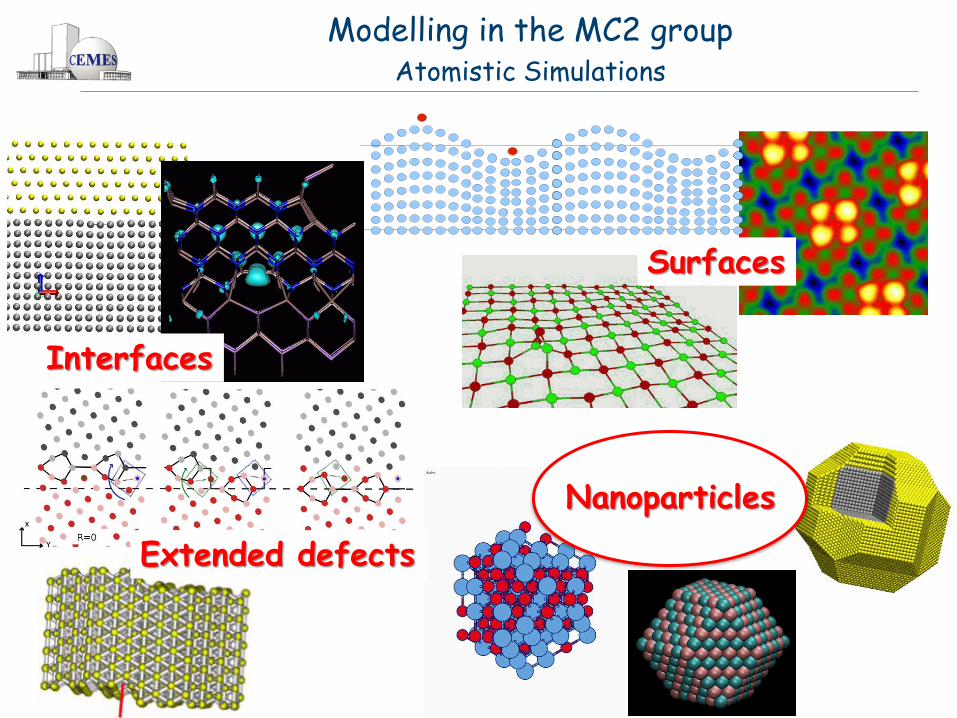
Modelling in the MC2 group Atomistic Simulations
Interfaces
Extended defects
Nanoparticles
Surfaces

Modelling in the MC2 group Atomistic Simulations
Tight-Binding DFT
(DFTB)
Electronic structure Point atoms – T= 0K
DFT
Point atoms Empirical potentials Finite T
Monte Carlo
Molecular Dynamics
(MD)
‘’Quantum’’ atoms Finite T
Path Integrals
(PI)
ab initio MD
PI-MD ab initio PI-MD
Codes: LAMMPS, VASP, CPMD, CP2K, Gaussian, SIESTA, deMon, PINY-MD, ‘’in-house’’ codes…
Computers: Local cluster (~200 CPU), CALMIP Mesocentre, IDRIS and CINES
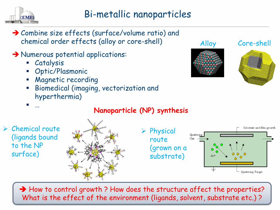
Bi-metallic nanoparticles
Combine size effects (surface/volume ratio) and chemical order effects (alloy or core-shell)
Numerous potential applications: Catalysis Optic/Plasmonic Magnetic recording Biomedical (imaging, vectorization and
hyperthermia) …
Nanoparticle (NP) synthesis
How to control growth ? How does the structure affect the properties? What is the effect of the environment (ligands, solvent, substrate etc.) ?
Chemical route (ligands bound to the NP surface)
Physical route (grown on a substrate)
Alloy Core-shell
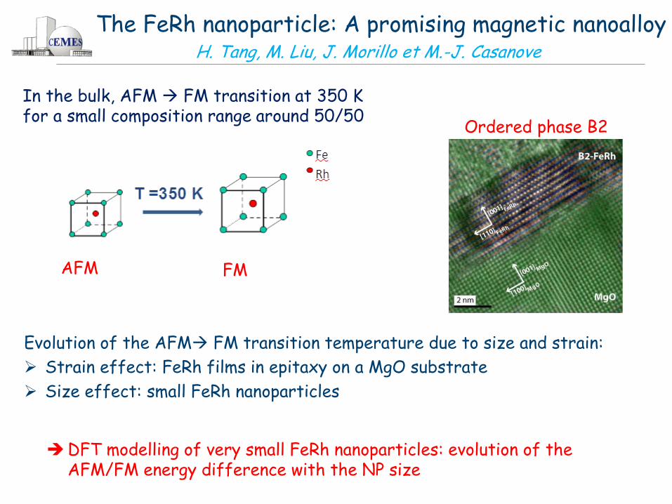
The FeRh nanoparticle: A promising magnetic nanoalloy
Ordered phase B2
Evolution of the AFM FM transition temperature due to size and strain:
Strain effect: FeRh films in epitaxy on a MgO substrate
Size effect: small FeRh nanoparticles
AFM FM
DFT modelling of very small FeRh nanoparticles: evolution of the AFM/FM energy difference with the NP size
H. Tang, M. Liu, J. Morillo et M.-J. Casanove
In the bulk, AFM FM transition at 350 K for a small composition range around 50/50
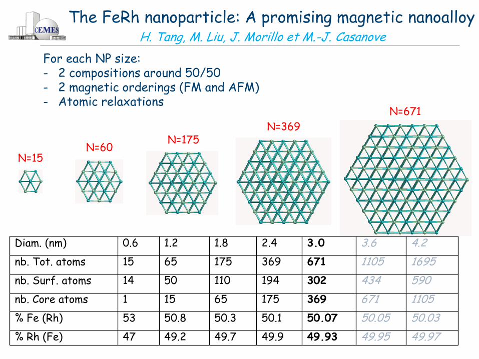
Diam. (nm) 0.6 1.2 1.8 2.4 3.0 3.6 4.2
nb. Tot. atoms 15 65 175 369 671 1105 1695
nb. Surf. atoms 14 50 110 194 302 434 590
nb. Core atoms 1 15 65 175 369 671 1105
% Fe (Rh) 53 50.8 50.3 50.1 50.07 50.05 50.03
% Rh (Fe) 47 49.2 49.7 49.9 49.93 49.95 49.97
The FeRh nanoparticle: A promising magnetic nanoalloy H. Tang, M. Liu, J. Morillo et M.-J. Casanove
For each NP size: - 2 compositions around 50/50 - 2 magnetic orderings (FM and AFM) - Atomic relaxations
N=15 N=60
N=175 N=369
N=671

The FeRh nanoparticle: A promising magnetic nanoalloy H. Tang, M. Liu, J. Morillo et M.-J. Casanove
For small sizes, the FeRh NPs are preferentially FM at 0K (in agreement with very recent experimental measurements)
The FM AFM transition takes place around 4.2 nm How does the AFM FM transition temperature evolve with size ?

The FeRh nanoparticle: A promising magnetic nanoalloy H. Tang, M. Liu, J. Morillo et M.-J. Casanove
HPC ressources (Hyperion, Calmip): For a FeRh NP of 3 nm – VASP code - # atoms = 671 - # electrons = 5703 - # bands = 3928
VASP version
# PW RAM SCF loop Storage
Γ-point 1098203 4.5 Gb/core 1600 sec. 138 Gb
‘’normal’’ 2160921 6 Gb/core 3200 sec. 239 Gb
Need for efficient parallelization (eg, VASP is not really scalable beyond 128 CPU…)
Need for large RAM
Core-shell Fe@Au Nanoparticles M. Benoit, N. Combe, N. Tarrat, J. Morillo and M.-J. Casanove
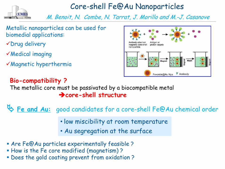
Metallic nanoparticles can be used for biomedial applications:
Drug delivery
Medical imaging
Magnetic hyperthermia
Bio-compatibility ? The metallic core must be passivated by a biocompatible metal
core-shell structure
Bi@Fe3O4
• low miscibility at room temperature
• Au segregation at the surface
Fe and Au: good candidates for a core-shell Fe@Au chemical order Are Fe@Au particles experimentally feasible ? How is the Fe core modified (magnetism) ? Does the gold coating prevent from oxidation ?

Core-shell Fe@Au Nanoparticles M. Benoit, N. Combe, N. Tarrat, J. Morillo and M.-J. Casanove
{001} Fe Facets : (001)Au[100]Au//(001)Fe[110]Fe
{110} Fe Facets :(111)Au[1-10]Au//(110)Fe[001]Fe
Irregular Janus
Large nanoparticles
Regular
Size of the Fe nanocube: 5- 10 nm
HRTEM Image
What is the equilibrium morphology ?
Is there a critical size ?
What happens at the interface ?
Au
Fe

DFT calculations of the Au(001)/Fe(001) interface (periodic slabs):
Number of Au planes
In-plane strain ԑ//
(mismatch between Fe and Au lattice parameters)
vacuum
ԑ//
Fe
Au
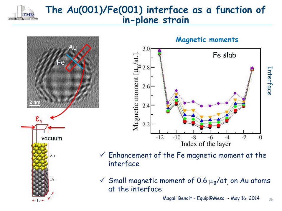
Magnetic moments
Fe slab
Enhancement of the Fe magnetic moment at the interface
Small magnetic moment of 0.6 B/at on the Au atoms at the interface
Interface
ԑ//
Core-shell Fe@Au Nanoparticles M. Benoit, N. Combe, N. Tarrat, J. Morillo and M.-J. Casanove

Work of adhesion Wad as a function of the in-plane strain and of the number of Au planes
In-plane strain Number of Au planes
Wad increases when the Fe substrate in strained
Higher Wad for 2 Au monolayers strong coupling between the interface
Fe orbitals and the surface Au orbitals
Core-shell Fe@Au Nanoparticles M. Benoit, N. Combe, N. Tarrat, J. Morillo and M.-J. Casanove

Core-shell Fe@Au Nanoparticles M. Benoit, N. Combe, N. Tarrat, J. Morillo and M.-J. Casanove
DFT evaluation of the surface and interface energies and stresses Inputs for a simple model:
Evolution of the equilibrium strain state of the core as a function of the Fe/Au volume ratio
Relative weight of the surface (λ) and interface (μ) elastic contributions
DFe= 1 nm DAu= 10 nm
Surface elastic effects are important for smaller 20 nm and are dominant for smaller than 2.3 nm
Interface elastic effects can not be neglected for thin shells
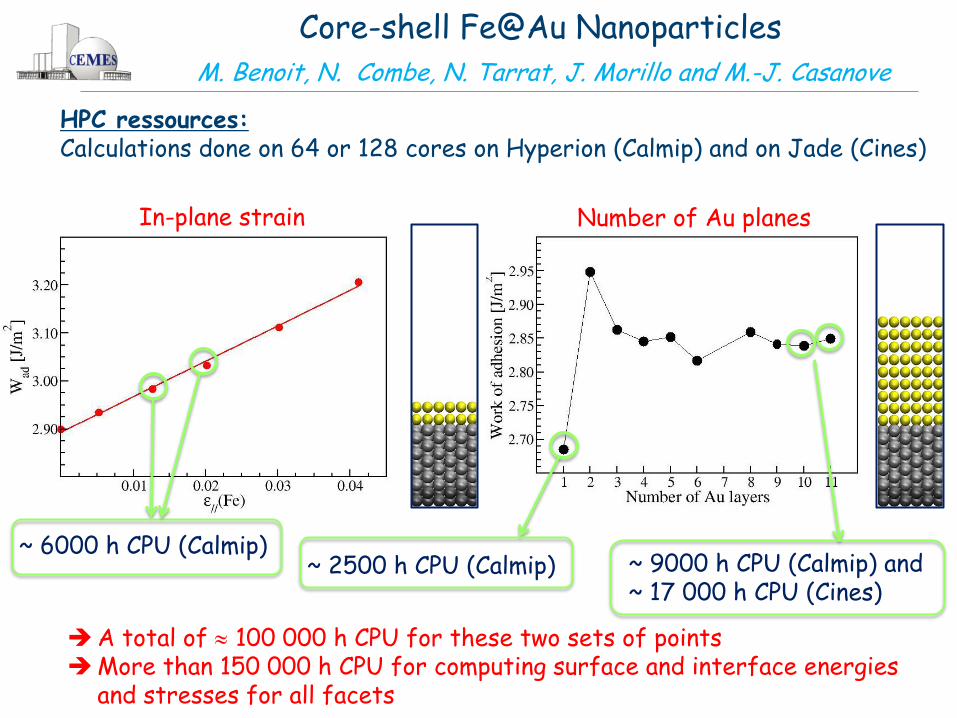
HPC ressources: Calculations done on 64 or 128 cores on Hyperion (Calmip) and on Jade (Cines)
In-plane strain Number of Au planes
Core-shell Fe@Au Nanoparticles M. Benoit, N. Combe, N. Tarrat, J. Morillo and M.-J. Casanove
~ 6000 h CPU (Calmip) ~ 9000 h CPU (Calmip) and ~ 17 000 h CPU (Cines)
~ 2500 h CPU (Calmip)
A total of 100 000 h CPU for these two sets of points More than 150 000 h CPU for computing surface and interface energies
and stresses for all facets

Core-shell Fe@Au Nanoparticles M. Benoit, N. Combe, N. Tarrat, J. Morillo and M.-J. Casanove
DFT modelling of an entire nanoparticle ? Limited to a few hundred atoms…
Critical size for the change of equilibrium
morphology 10 nm ( 100000 atoms !)
Monte Carlo simulations with a semi-empirical potential (with F. Calvo, Grenoble)
DFT modelling of bio-molecules grafted on the NP surface ?
Large size systems with electronic description
Density-Functional Tight-binding (DFTB) of the NP-molecule system (with M. Rapacioli, LCPQ, Toulouse)
Magali Benoit – Equip@Meso - May 16, 2014 17
Conclusion
DFT simulations of metallic nanoparticles: Access to electronic and magnetic properties Chemical interaction with the environment (ligands, solvent etc.)
But limited to small sizes ! Because size effects are important around 5-10 nm, need for large scale calculations: Large scale DFT calculations ? Localized orbitals ? Approximate DFT ? DFTB… (much) larger HPC ressources ?
Meanwhile, alternatives are developed multi-scale approach (electronic atomistic)
Fast and easy access to computing ressources is extremely important Direct contact with scientific computing engineers is a definite plus
Mesocenters are essential for our work !
Magali Benoit – Equip@Meso - May 16, 2014 18
THANKS o Theory, DFT and DFTB calculations:
Nicolas Combe (CEMES, Toulouse) Hao Tang (CEMES, Toulouse) Nathalie Tarrat (CEMES, Toulouse) Joseph Morillo (CEMES, Toulouse) Mathias Rapacioli (LCPQ, Toulouse)
o CALMIP team:
Nicolas Renon Pierrette Barbaresco Boris Dintrans
o Computer ressources:
CALMIP (Regional center, Toulouse) CINES (National center, Montpellier)
IDRIS (National center, Paris)
C E M E S
o COST Nanoalloys o ANR SimNaNa o Labex NEXT ‘’CIM3’’ project

Magali Benoit – Equip@Meso - May 16, 2014 19
The Fe-Au system
Bi@Fe3O4
• low miscibility at room temperature
• Au segregation at the surface
4.0782 Å
2.8665 Å
A good candidate for a core-shell Fe@Au chemical order
Are Fe@Au particles experimentally feasible ?
How is the Fe core modified (magnetism) ?
Does the gold coating prevent from oxydation ?

Magali Benoit – Equip@Meso - May 16, 2014 20
Synthesis conditions
Fe growth : 3D growth with neat facets
requires a growth temperature > 700 C
500 C 700 C
Au growth : avoid nucleation of pure Au
particles high T (optimized 800 C)
Fe : Deposited thickness 2 nm Fe@Au : 2 nm @ 1nm
Bi@Fe3O4
Sequential procedure by dc magnetron sputtering Substrate : 5 nm Al2O3 amorphous film on NaCl substrate
Capping layer : 5 nm Al2O3 amorphous film
Al2O3
NaCl
Magali Benoit – Equip@Meso - May 16, 2014 21
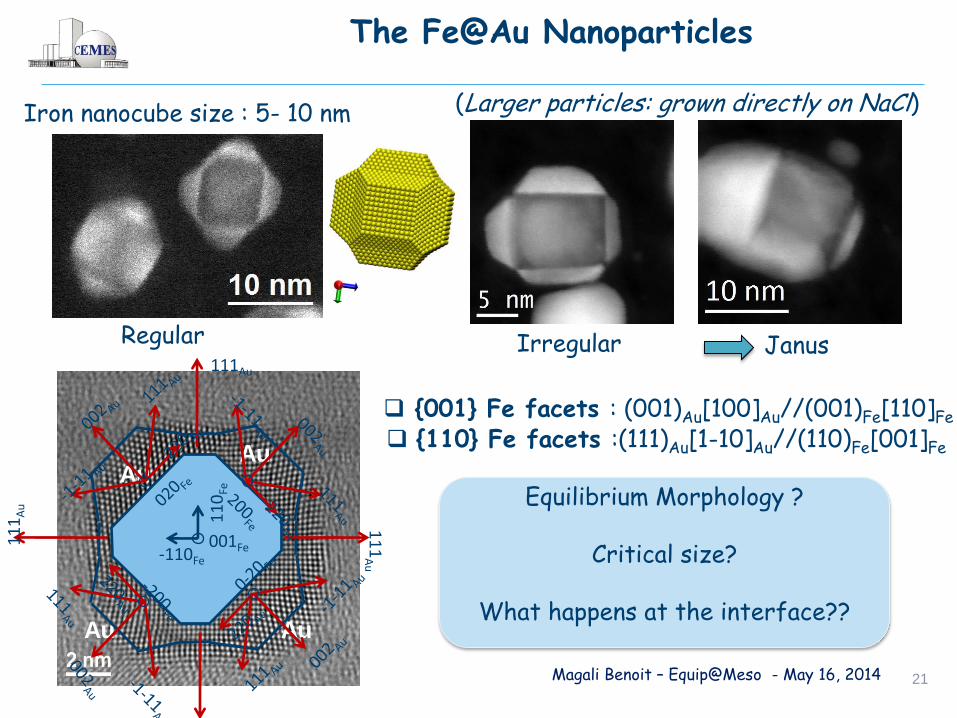
The Fe@Au Nanoparticles
Regular Irregular Janus
(Larger particles: grown directly on NaCl) Iron nanocube size : 5- 10 nm
Equilibrium Morphology ?
Critical size?
What happens at the interface??
Fe
Au Au
Au Au
11
0Fe
-110Fe
111Au
11
1A
u
11
1A
u
001Fe
{001} Fe facets : (001)Au[100]Au//(001)Fe[110]Fe
{110} Fe facets :(111)Au[1-10]Au//(110)Fe[001]Fe

Magali Benoit – Equip@Meso - May 16, 2014 22
Growth under stress
Au grows on (100)Fe facets under compressive biaxial stress
Misfit : Da/a = (aL-aS)/aL = 0.60 %
Substrate
Layer aL
aS
In plane strain e// = - Da/a
Out of plane strain e┴ = -
2 C12
C11
e//
Au pyramides submitted to compressive
biaxial stess e//Au
= - 0.60%
e┴ Au = 1.02%
Au
Au
e┴
e//
Fe
Simulated : e//
Au ~ - 0.5%
e┴ Au
~ 0.77% at the interface
Fe core- slightly expanded
Finite Elements
Magali Benoit – Equip@Meso - May 16, 2014 23
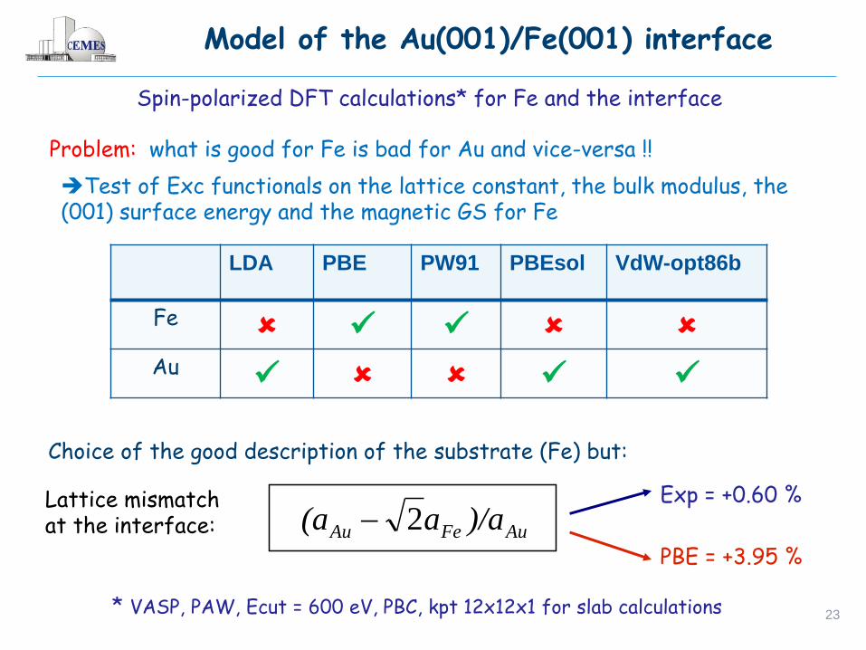
Model of the Au(001)/Fe(001) interface
Spin-polarized DFT calculations* for Fe and the interface
* VASP, PAW, Ecut = 600 eV, PBC, kpt 12x12x1 for slab calculations
Problem: what is good for Fe is bad for Au and vice-versa !!
LDA PBE PW91 PBEsol VdW-opt86b
Fe
Au
Test of Exc functionals on the lattice constant, the bulk modulus, the (001) surface energy and the magnetic GS for Fe
Choice of the good description of the substrate (Fe) but:
Lattice mismatch at the interface:
Exp = +0.60 %
PBE = +3.95 % AuFeAu )/aa(a 2
Magali Benoit – Equip@Meso - May 16, 2014 24
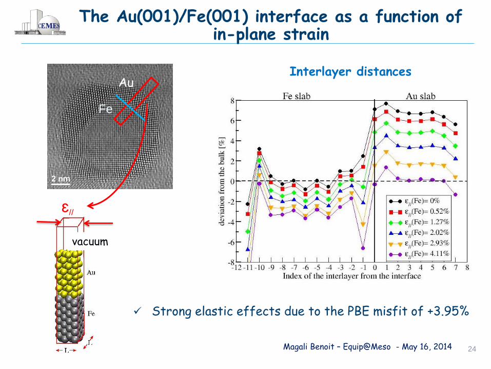
The Au(001)/Fe(001) interface as a function of in-plane strain
Interlayer distances
Strong elastic effects due to the PBE misfit of +3.95%
vacuum
ԑ//
Fe
Au
Magali Benoit – Equip@Meso - May 16, 2014 25
Magnetic moments
Fe slab
Enhancement of the Fe magnetic moment at the interface
Small magnetic moment of 0.6 B/at. on Au atoms at the interface
Inte
rface
The Au(001)/Fe(001) interface as a function of in-plane strain
vacuum
ԑ//
Fe
Au

Magali Benoit – Equip@Meso - May 16, 2014 26
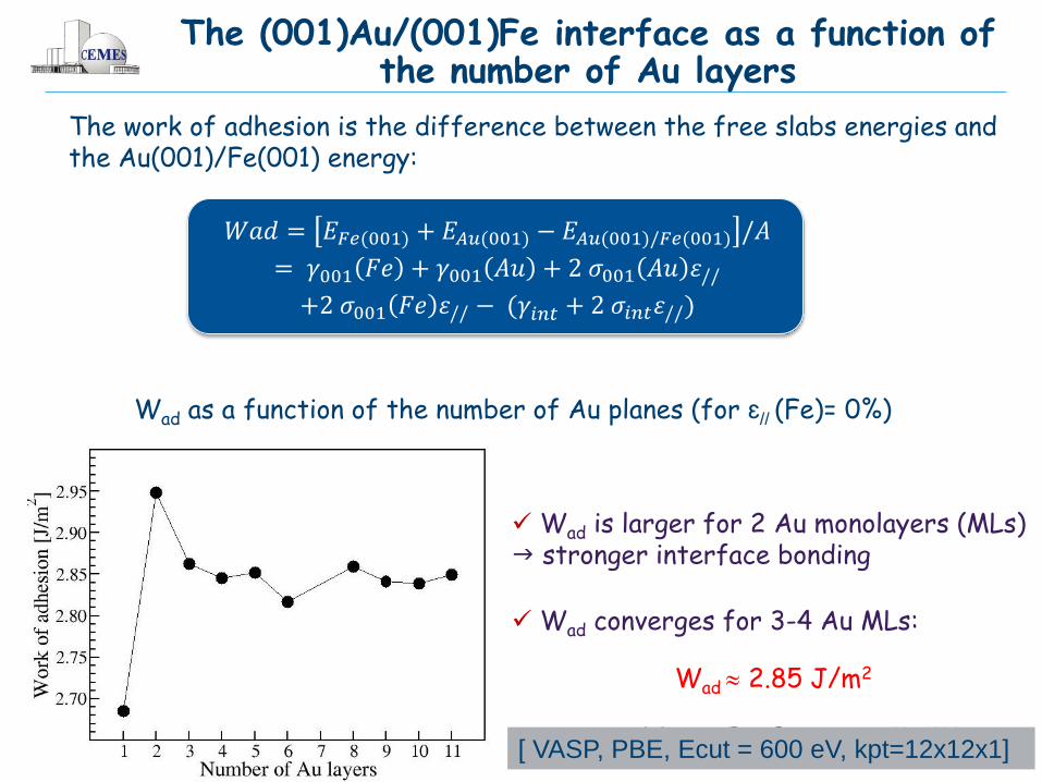
𝑊𝑎𝑑 = 𝐸𝐹𝑒(001) + 𝐸𝐴𝑢(001) − 𝐸𝐴𝑢(001)/𝐹𝑒(001) /𝐴
= 𝛾001 𝐹𝑒 + 𝛾001 𝐴𝑢 + 2 𝜎001 𝐴𝑢 𝜀//
+2 𝜎001 𝐹𝑒 𝜀// − (𝛾𝑖𝑛𝑡 + 2 𝜎𝑖𝑛𝑡𝜀//)
The work of adhesion is the difference between the free slabs energies and the Au(001)/Fe(001) energy:
Interface energy
gint= 0.458 J/m2 sint = - 0.532 J/m2
(Fe as reference)
gint= 0.389 J/m2 sint = -0.401 J/m2
(Au as reference)
Wad as a function of in-plane strain 𝜀// (for 8 Au planes)
The Au(001)/Fe(001) interface as a function of in-plane strain
//001001//intint//001001 222 esgesgesg AuAuFeFeS
Wetting parameter S >0
Magali Benoit – Equip@Meso - May 16, 2014 27
The (001)Au/(001)Fe interface as a function of the number of Au layers
Wad as a function of the number of Au planes (for ԑ// (Fe)= 0%)
Wad is larger for 2 Au monolayers (MLs) stronger interface bonding
Wad converges for 3-4 Au MLs:
Wad 2.85 J/m2
[ VASP, PBE, Ecut = 600 eV, kpt=12x12x1]
The work of adhesion is the difference between the free slabs energies and the Au(001)/Fe(001) energy:
𝑊𝑎𝑑 = 𝐸𝐹𝑒(001) + 𝐸𝐴𝑢(001) − 𝐸𝐴𝑢(001)/𝐹𝑒(001) /𝐴
= 𝛾001 𝐹𝑒 + 𝛾001 𝐴𝑢 + 2 𝜎001 𝐴𝑢 𝜀//
+2 𝜎001 𝐹𝑒 𝜀// − (𝛾𝑖𝑛𝑡 + 2 𝜎𝑖𝑛𝑡𝜀//)
Magali Benoit – Equip@Meso - May 16, 2014 28
The (001)Au/(001)Fe interface as a function of the number of Au layers
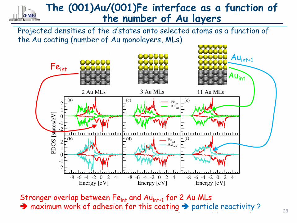
Projected densities of the d states onto selected atoms as a function of the Au coating (number of Au monolayers, MLs)
Feint
Auint+1
Auint
Stronger overlap between Feint and Auint+1 for 2 Au MLs maximum work of adhesion for this coating particle reactivity ?

Magali Benoit – Equip@Meso - May 16, 2014 29
The (001)Au/(001)Fe interface as a function of the number of Au layers
Charge density difference: )()()()( **
/ rrrr FeAuFeAu D
*Au and *
Fe are the charge densities of Au and Fe slabs with atoms fixed at their positions in the Au(001)/Fe(001) interface
D > 0 deficit of electrons due to the interface
D < 0 excess of electrons due to the interface

Conclusion and work in progress
Core@shell nanostructures synthesized through PVD techniques:
cristalline nanoparticles with neat facets
original morphologies – ‘’growth on a nanosubstrate’’
DFT interface energy in agreement with particle morphology
Strong enhancement of the Fe magnetic moment at the interface
Stronger adhesion for 2 Au MLs, whatever the in-plane strain
Implication for the nanoparticle reactivity ?
Perspectives:
Simulating the whole nanoparticle (EAM pot., DFTB ?)
Look at the Au(2 ML)/Fe reactivity
DFT: M. Benoit et al., Phys. Rev. B 86, 075460 (2012)
Exp: M.-J. Casanove et al., in preparation

Magali Benoit – Equip@Meso - May 16, 2014 31
Bi@Fe3O4
CEMES, Toulouse, France

Magali Benoit – Equip@Meso - May 16, 2014 32
Synthesis conditions
Bi@Fe3O4
Sequential procedure by dc magnetron sputtering
Substrate : 5 nm Al2O3 amorphous film on NaCl substrate
Capping layer : 5 nm Al2O3 amorphous film
1st step : Al2O3 substrate preparation (RT)
2nd step : Fe deposition
3rd step : Au deposition
4th step : Al2O3 capping layer (RT)
Al2O3
NaCl
RF and DC Magnetron Sputtering