bhaskar dutta - semantic scholar...molding/die casting •tool reconfiguration for engineering...
TRANSCRIPT
The AMMTIAC Quarterly, Volume 6, Number 2 5 http://ammtiac.alionscience.com
Direct metal deposition (DMD) is an advanced additive manufac-turing technology that enables repair and rebuild of worn/damagedcomponents, as well as manufacture of new components. The tech-nology is an extension of rapid prototyping, however, in contrast tomost rapid prototyping processes, DMD produces fully dense,functional metal parts. Parts are made directly from the computer-aided design (CAD) drawing by depositing metal powder pixel-by-pixel utilizing laser melting and a patented closed-loop controlsystem to maintain dimension and quality).[1] The same process isextended for remanufacturing of damaged components, such as gas turbine blades and stator vanes (see Figure 1).[2, 3] Besidesremanufacturing, DMD can build wear-resistant coatings and
other features on complex, high-value components. With its closed-loop feedback system and six-axis deposition capability, DMD cancoat and rebuild parts with a very complex geometry.[4] This arti-cle presents an overview of the DMD process and a few case studiesinvolving remanufacturing of used parts, as well as manufacturingof new parts. It also discusses benefit of such technology insertionin DoD.
PROCESS OVERVIEWDirect metal deposition is a proprietary laser aided manufacturing(LAM) process that originated at the University of Michigan and isbeing further developed and commercialized. Although LAM hasplayed a key role for repair of aerospace components for more thana decade, DMD provides a major advancement of the technology.
The preliminary work ondirect metal deposition ofaluminum has been demon-strated to provide metalproperties equivalent tothose of wrought material,thus making it potentiallyuseful for the direct fabrica-tion of parts.[1] Since then,
the technology has been advanced significantly and has been appliedto a wide range of alloys and components.An industrial laser beam under computer numerical control
(CNC) is focused onto a workpiece, producing a melt pool. A smallamount of powdered metal is injected into the melt pool, buildingup the part in a thin layer. The beam follows a toolpath generatedbased on the CAD data, tracing out the part layer by layer. DMD machines are equipped with a three or five-axis head with
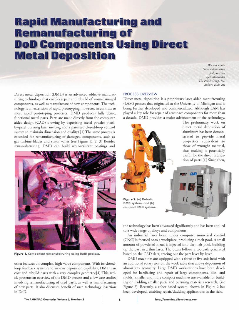
an additional rotary axis on the work table that allows deposition ofalmost any geometry. Large DMD workstations have been devel-oped for hardfacing and repair of large components, dies, andmolds. Smaller and more compact machines are available for build-ing or cladding smaller parts and pursuing materials research, (seeFigure 2). Recently, a robot-based system, shown in Figure 2 hasbeen developed, enabling repair/cladding applications in the field.
Bhaskar Dutta Shiva Palaniswami
Joohyun ChoiJyoti Mazumder
The POM Group, Inc.Auburn Hills, MI
Figure 1. Component remanufacturing using DMD process.
Figure 2. (a) RoboticDMD system, and (b)compact DMD system.

The AMMTIAC Quarterly, Volume 6, Number 2 6 http://ammtiac.alionscience.com
Some of the main features of the system include:• Co-axial nozzle design gives full five-axis deposition capabilityversus side powder-feed systems, which can only deposit linearlyin motion along with local shielding by inert gases
• “Moving optics” capability allows processing of large, heavy parts• Patented closed-loop optical feedback system monitors and con-trols the melt pool in real time, resulting in a near net shapepart[6]
• Proprietary tool path software translates CAD data into the noz-zle motion for six-axis deposition
• Multiple powder delivery system allows deposition of differentmaterials simultaneously or consecutively at specified locations,enabling production of on-the-fly alloys/composites
• Deposits are fully dense and create a true metallurgical bond withthe substrate/part. DMD has been used successfully on a broadrange of materials, including, tool steels, stainless steels, highspeed steels, and alloys of nickel, cobalt, titanium, aluminum, andcopper.
• Multi-functional software for normal production jobs and forresearch and development activities
• Inert chamber atmosphere for deposition of reactive materials,such as titanium, tantalum, molybdenum, etc.
Feedback SystemThe DMD closed loop feedback system is the key tool for produc-ing a near net-shape product. The system consists of high-speed
sensors with optics looking at the melt pool (see Figure 3). Thesensors collect the melt pool image, which is then directly fed intoa dedicated controller. The controller extracts the melt pooldimensional data from this signal.A software algorithm processes the data, and controls the laser
power in order to maintain a consistent melt pool. Tight control ofthe laser power means tight control of the layer thickness, and thisresults in the near net shape of the final product. The feedback sys-tem also allows control of heat input by controlling melt pooldimensions. This in turn leads to minimal heat-affected zone and abetter microstructure with superior properties.
Deposition SoftwareSix-axis deposition software (DMDCAM) for additive manufactur-ing builds a CAM tool path directly from CAD data. It includes anintegrated direct metal deposition database with process recipes as apart of the software. Contour, surface, and volume deposition pathsare provided in three dimensions, and multi-layer deposition pathscan be prepared in a single operation.Simulation and collision-detection modules are included for a
“Ready to Use” deposition path. They detect any possible collisionof the processing head and the part while creating the depositiontool path. The modules enable the user to search for alternate toolpath strategies.
Vision SystemThe vision system has been developed for deposition on small partswith fine features, such as turbine blades. When a part is placed onthe machine table, cameras take an image of the area of depositionand the image coordinates are translated to machine coordinates.This eliminates manual part pick-up, which is practically impossi-ble for very small components with fine features. Intermittent imag-ing can even allow inspection and adjustment of tool paths forrequired part geometry.The vision software also has in-built tool pathing capability
that allows direct-deposition path creation from the acquiredimage for simpler geometries. This is particularly useful forremanufacturing applications in which CAD data of a damaged orworn out part is no longer available. Figure 4 shows an example ofa turbine blade image taken by the vision system. This was fol-lowed by an automatic edge detection and subsequent tool pathgeneration with or without offsetting the edge, as required by theuser. Vision system software is capable of having different process-ing parameters at different points, as shown in Figure 4. This is
Figure 3. Schematic showing closed loop feedback system.
Figure 4. Left: Demonstration of DMD vision system capability, Right: As deposited turbine blade squealer tip in DMD system.
Final Focus Optics
To Powder Feeder
Laser Beam
Nozzle Shielding Gas
Workholding Fixture
Feedback Sensor 1
Substrate or Die Preform
Solid Free FormShape by DirectDeposition
Feedback Sensor 2
Blade Picture
Modify blade profile andset point process parameter
(Development mode)
Automatic NC filegeneration with
point wise process data

The AMMTIAC Quarterly, Volume 6, Number 2 7 http://ammtiac.alionscience.com
critical for components with vast geometry variations, such as tur-bine blades in which the trailing edge can be very thin comparedto the rest of the component.
DMD MATERIALSAs-deposited material is fully dense, and its mechanical and phys-ical properties can be as good as or better than those of compara-ble cast or wrought materials. Table 1 shows tensile and hardnessdata of some typical materials, such as IN625, Stellite 31, and Ti-6Al-4V. The table compares DMD materials with wrought orcast materials. Note that the DMD materials can be fully stress-relieved, heat-treated, and aged to alter the microstructures forspecific applications and to improve ductility or toughness.DMD has been successfully applied in a wide range of materialsincluding, various, steels, Ni-alloys, Co-alloys, Ti-alloys, Al-alloys, Cu-alloys, refractory metals, such as Ta, and cermets (i.e.,metal-ceramic composites).
APPLICATIONSDMD is suitable for a broad range of applications covering indus-tries from defense to aerospace, from automotive to oil and gas,from injection molding to medical, from tool and die tomining/construction. Examples of applications, include:• Repair and restoration of expensive components, such as, gasturbine components
• Building of near net shape parts/features for new part fabrica-tion, such as aerospace components, medical components, etc.
• Wear or corrosion resistant coatings on parts/dies/tools etc. forlonger life
• Conformal cooling for higher productivity in plastic injectionmolding/die casting
• Tool reconfiguration for engineering changes to productiontooling
REMANUFACTURING One of the areas best suited for DMD is remanufacturing of wornout and/or damaged components. DMD can rebuild worn out orcorroded surfaces by adding the same or similar metal to the dam-aged part. The concentrated heat of the laser source limits the sizeof the heat affected zone (HAZ) and minimizes microstructuraldamage of the parent part. This ensures that the integrity of therepaired part is good.Damaged turbine components including, blades/vanes, bear-
ings, seals, bearing housing are great candidates for DMD repair.The DMD vision system plays a significant role in remanufactur-ing of the worn out turbine vanes. Easy and precision part pickuphelps in reliable and rapid remanufacturing of these high valuecomponents. Closed-loop feed back system controls the heatinput into the part, and results in a quality product that requiresminimal post grinding. Figure 5 shows the cross-sectionmicrostructures of the DMD area of a repaired turbine blade.Excellent process control leads to a fully dense microstructure, asobserved in the vertical cross-section along with a small heataffected zone.DMD can also be used to repair cracked components. Figure 6
shows a case study of a large casting from a stamping press thatdeveloped cracks upon extended service due to constant fatigueloading of the component. The cracked area was machined to
Figure 6. Large component remanufacturing using DMD. Right bottom shows a cracked area machined back. This was filled backusing DMD deposited steel.
Figure 5. Macro (a) and microstructures (b-d) of DMD deposited Ti-6Al4V, and (b) the clad, (c) the interface and (d) the base material.
Table 1. DMD vs. conventionally fabricated nickel, cobalt, and titanium alloys.Material Condition Tensile Yield Elongation, Hardness,
Strength, Strength, % HRCMPa MPa
IN 625 DMD As deposited 795 598 14 13
IN 625 Wrought 927°C Annealed 897 483 40 16
Stellite 31 DMD As deposited 1182 903 6 40
Stellite 31 Cast As cast 662 386 10 33
Ti-6Al-4V DMD As deposited 1163 1071 8 38
Ti-6Al4V (V) Wrought Annealed 950 880 14 36
(a)
(c)
(d)
1 mm
20 μm
20 μm
200 μmHAZ 300 μm
(b)

remove the crack completely, rebuiltusing DMD process, and re-machinedto final specification. The componenthas been back in service and performingsuccessfully. A significant cost savingwas obtained due to high value and longlead time of the new castings. Thisdemonstrates the ability of DMD torepair and remanufacture large compo-nents without sacrificing theirintegrity.Figure 7 shows microstructure
and mechanical properties ofDMD deposited 4340 steel forsuch a component. A metallurgi-cal bond with no defects and ashort heat affected zone (HAZ)are observed in the microstruc-ture (see Figure 7a). As a result offast cooling during DMD, thecladding exhibits a martensitic structure.Figure 7(b) shows tensile properties ofthe as deposited material and comparesit with the substrate 4340 steel. Resultsshow that the DMD material is substan-tially stronger than the wrought 4340steel. To estimate the strength of a DMDrepaired component, a sample was pre-pared in which half of the material was4340 wrought steel and half of the sam-ple was built using DMD. This sampleexhibits similar strength as wrought4340 steel. Fracture surface investigationalso shows that failure occurred throughwrought 4340 steel. These data conclu-sively prove that the DMD repairedmaterial has excellent strength and canbe successfully used for remanufacturingapplications.
FREE FORM FABRICATIONVery intricate and complex features andparts that contain such features are pos-sible with DMD. An example of this isshown in Figure 8, in which a mirrorhousing (see Figure 8a) was built fromscratch under a NASA sponsored proj-ect. The closed-loop feedback controlsystem allowed uniform build-up withno intermediate machining step.The part was conventionally built
from a solid piece of metal by electro-discharge machining (EDM), which is aslow process that generates a significantamount of waste. Figure 8(b) comparesthe efficiency of the DMD and EDMprocesses in terms of material, energy,and time. Clearly, DMD requires onlyabout a third as much material as EDM,
and this results in a huge savings, espe-cially for expensive aerospace materials,such as nickel-base super alloys. In termsof process time and energy, DMD con-sumes only 4% and 80%, respectively ascompared to a conventional process. Besides its ability to build complex
geometries, DMD can build a singlepart with multiple materials to provide
functional properties at differ-ent segments/surfaces of a part.Multiple hopper capability ofDMD systems makes this feasi-ble, and easy while maintainingproductivity.
BENEFITS TO DODMaintaining battle readiness forthe armored vehicles, fighterjets, naval vessels, while manag-ing inventory costs has been a
constant challenge for the DoD. Longlead-times and high costs of procuring,inventorying and transporting replace-ment parts has resulted in a reduction ofequipment readiness rates, while DoDoperation and support costs haveincreased. Insertion of additive manufac-turing technologies, such as DMD canbenefit the DoD. DMD can eitherremanufacture damaged parts, or replacethem by creating new parts from CADdata. Field deployable DMD systems thatcan be carried with mobile Army units orAircraft carriers and used for spare partmanufacturing have been built.Ground vehicles, such as tanks and
automobiles, have numerous parts thatundergo extensive wear and tear due tothe aggressive operational environment.The components are expensive, and spareparts are sometimes in limited supply ornot available. In order to maintain theforce readiness, it is essential to have theparts replaced as needed. In case of theNavy, the severe sea water corrosion is themain cause for damage and failure ofsubmarine or other vessel components.DMD has been applied successfully tosalvage some of these damaged parts, andit has been demonstrated that a properinsertion of such a technology can effectsignificant savings for the Navy. For theAir Force stringent safety requirementsdemand that remanufactured parts are asgood as new, or better. DMD has thecapability of meeting these challengesdue to its superior process control ascompared to other open loop processes.
The AMMTIAC Quarterly, Volume 6, Number 2 8 http://ammtiac.alionscience.com
Figure 8. (a) A mirror housing built by DMDprocess. (b) Comparison of DMD and EDMprocess efficiency for building the housing.
100%
90%
80%
70%
60%
50%
40%
30%
20%
10%
0%
EDM
DMD
Process Process Process Volume Time Energy
(a)
(b)
Figure 7. (a) Microstructure of laser deposited4340 steel, and (b) tensile properties of DMD4340 steel, wrought 4340 steel for comparison,and a sample with half wrought 4340 and halfDMD 4340 steel.
100 μm

The AMMTIAC Quarterly, Volume 6, Number 2 9 http://ammtiac.alionscience.com
To comment on this article, email: [email protected]
Dr. Bhaskar Dutta, Chief Operations Officer of POM Group, has a M.E. and a Ph.D in Metallurgical Engineering. He has more than 20 yearsof experience in academia and industry. Dr. Dutta has more than 40 technical publications.
Shiva Palaniswami is the Vice President Business Development at POM Group. He has a M.S. in Mechanical Engineering and a Masters inBusiness Administration, with 20 years of experience in the manufacturing industry.
Dr. Joohyun Choi is the Director Engineering at POM. He has a M.S. and a Ph.D in Mechanical Engineering. Dr. Choi has more than 25 yearsexperience in additive manufacturing and laser processing, both in academia and industry.
Dr. Jyoti Mazumder is the Chief Executive Officer of POM Group and Robert H. Lurie Professor of Mechanical Engineering in the University ofMichigan. He is one of the founders of the POM Group and inventor of Closed Loop Direct Metal Deposition technology. Dr. Mazumder has aD.I.C. and a Ph.D. in Metallurgy. He has more than 325 technical papers, co-authored 2 books, edited 9 books and awarded 16 patents, all inthe field of laser materials processing.
DMD-based part restoration practice will also offer the DoD anopportunity to demonstrate its commitment for more environmen-tally friendly processes. DoD depots currently use a chrome platingprocess to refurbish damaged components. This process produceshexavalent chromium as a by-product, which is a well-known car-cinogen. The DoD is undergoing an effort to minimize this process.An additive manufacturing technology, such as DMD, can offer analternative to the use of hexavalent chromium. Moreover, the addi-tive nature of DMD technology leads to material and energy savingscompared to a subtractive machining process.DMD technology can be used to improve wear, corrosion,
fatigue resistance, and other mechanical properties of expensiveDoD components. Based on the damage pattern of high cost DoDcomponents, selective deposition can be applied on new parts toobtain significant life enhancement in these critical parts. This canlead to improved vehicles and armor components.
REFERENCES[1] Koch, J. L., and J. Mazumder, “Rapid Prototyping by Laser Cladding,”ICALEO (ed. by P. Denney, I. Miyamoto and B. L. Mordike), Vol. 77,1993, pp. 556-565.[2] Gao J., J. Folkes, O. Yilmaz, and N. Gindy, “Investigation of a 3DNoncontact Measurement Based Blade Repair Integration System,” AircraftEngineering & Aerospace Technology, Vol. 77, No 1, pp 34-41.[3] Dutta B., H. Natu, and J. Mazumder, “Near Net Shape Repair andRemanufacturing of High Value Components Using DMD,” TMS AnnualConference, February 2009.[4] Dutta B., “Surface Modification by Direct Metal Deposition Process:Technical Challenges, Opportunities and Performance Benefits,” Proc. MatSci.Tech., October 2008.[5] Koch J. and J. Mazumder, US Patent #6,122,564.
AMMTIAC Success Story
Diversifying The Energy Supply: The DoD Energy HandbookThe Department of Defense (DoD) faces the challenge of reducing its totalenergy footprint by minimizing its dependence on traditional fuels, enactinggreater operating efficiencies, and turning more to renewable energysources; all while decreasing operating costs and lessening environmentalimpact. A great deal of information on renewable and alternative energytechnologies already exists, but is scattered through a number of disparatesources. What is required is a one-stop reference that provides both the
guidance and technical information necessary to assess and formulate power andenergy strategies for all DoD installations. To provide warfighters with ready access to critical powerand energy data in a cost-effective manner, the Defense Technical Information Center (DTIC) com-missioned AMMTIAC to develop an expansive handbook on alternative and renewable energystrategies for the DoD. The Department of Defense Energy Handbook: Alternative and RenewableEnergy Options for DoD Facilities and Bases is now available.
The handbook is a foundational guide to energy technologies and alternative powersources for DoD installations. It constitutes a first-of-its-kind asset for facility energy managers andtheir staffs, providing them with a one-stop, all-in-one resource to assess and evaluate options fortheir energy strategies. While only recently published, the handbook is already having a positiveimpact on Defense infrastructure. By accessing the common resources of the handbook rather thanindependently developing their own data, the Services will make great strides toward meeting theDoD’s energy goals and yield significant savings for the taxpayer.
To obtain a copy, contact AMMTIAC ([email protected]) or complete a survey and download the PDF from the AMMTIAC website: http://ammtiac.alionscience.com/energyhandbook. The hardcopy version can also be ordered from the AMMTIAC website:
http://ammtiac.alionscience.com/ammt/products.do?action=detail&code=AMMT-38