bermad electrically controlled on-off deluge valve · bermad believes that the safety of personnel...
TRANSCRIPT

[email protected] ● www.bermad.com The information contained in this document is subject to change without notice. BERMAD shall not be liable for any errors contained herein.
All Rights Reserved. © Copyright by BERMAD Control Valves.
IOM
Model: FP 400E-3D Sizes: 2"-12"
PI4PE09-400E-3D
Bermad Electrically Controlled On-Off Deluge Valve
Model: 400E-3D
INSTALLATION OPERATION
MAINTENANCE
Application Engineering
BERMAD
[email protected] ● www.bermad.com The information contained in this document is subject to change without notice. BERMAD shall not be liable for any errors contained herein.
All Rights Reserved. © Copyright by BERMAD Control Valves.
IOM
Model: FP 400E-3D Sizes: 2"-12"
PI4PE09-400E-3D
1. Safety First BERMAD believes that the safety of personnel working with and around our equipment is the most important consideration. Please read all safety information below and from any other relevant source before attempting to perform any maintenance function. Comply with all approved and established precautions for working with your type of equipment and/or environment. Authorized personnel should perform all maintenance tasks. Prior to performing a procedure, read it through to the end and understand it. If anything is not clear, ask the appropriate authority. When performing a procedure, follow the steps in succession without omission.
2. Description
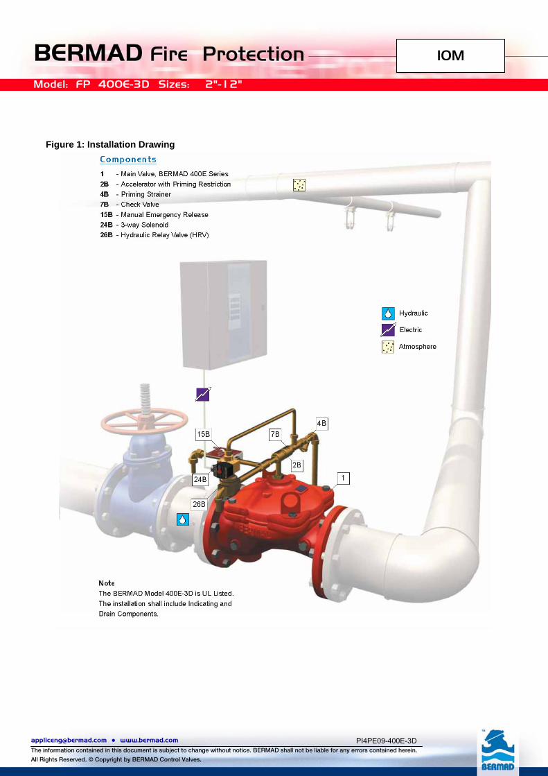
BERMAD 400E-3D Deluge Valve operates by an electric 3-Way Solenoid Valve (24b fig.1), which actuates a Hydraulic Relay Pilot Valve (26b fig.1) and requires a listed System Control Panel with a compatible electric detection System. The specific-trim for 400E-3D Deluge Valve includes a Hydraulic Relay Pilot Valve (HRV). The HRV is normally held closed by the actuating pressure maintained in the Hydraulic Supply System, and a Manual Emergency Release (15b fig.1).
In fire conditions, the fire activates the Detection System. The system’s control panel reacts and opens the Solenoid valve (24b fig.1), releasing pressure from the HRV and causing it to open. The open HRV releases the pressure from the upper chamber, allowing the Deluge Valve (1 fig.1) to open. Water enters the system piping and flows from any open sprinklers an/or spray nozzles. Deluge Systems are commonly used where it is desirable to simultaneously spray water from all open sprinklers and/or nozzles while the system is operating.
3. UL Listed
BERMAD 400E-3D Deluge Valve is UL Listed when installed with specific components & accessories. Refer to the current UL Directory. Consult the manufacturer for any component approval recently to appear in the UL fire protection equipment directory.
4. Installation
Subject to all other instructions, drawings and technical specifications which describe Bermad 400E-3D Deluge Valve, install in their proper positions the components comprising the Deluge Trim Package, according to the drawing relevant to the specific type, hereby enclosed. Install also the additional accessories, which appear in the drawing and which must be installed as shown in the drawing, although they are not packed together with the Bermad Deluge Valve itself. Any deviation in trim size or arrangement may adversely affect the proper operation of the Deluge Valve. Refer also to NFPA 13 or the applicable installation standards, codes and relevant authorities.
[email protected] ● www.bermad.com The information contained in this document is subject to change without notice. BERMAD shall not be liable for any errors contained herein.
All Rights Reserved. © Copyright by BERMAD Control Valves.
IOM
Model: FP 400E-3D Sizes: 2"-12"
PI4PE09-400E-3D
4.1. Allow enough room around the valve assembly for any adjustments and future maintenance/disassembly work.
4.2. Before the valve is installed, flush the pipeline to remove any dirt, scale, debris, etc. Failure to do this might render the valve inoperable.
4.3. Listed indicating valves should be installed upstream and downstream of the BERMAD 400E-3D Deluge Valve in such a way to allow for future maintenance.
4.4. Install the valve in the pipeline with the valve flow arrow on the body casting in the proper direction. Use the lifting eye provided on the main valve cover for lifting and lowering the valve.
4.5. BERMAD 400E-3D Deluge Valve is intended for horizontal or vertical installation. Ensure that the valve is positioned so that the actuator can be easily removed for future maintenance.
4.6. Install also the additional accessories, which appear in the drawing and which must be installed as shown in the schematic drawing.
4.7. Connect the electric wiring of the Solenoid Valve (24b fig.1) to the Electric Control System and the Control Panel according to the supplied Electrical Wiring Diagram.
4.8. When using a Pressure control switch, connect the Pressure Control Switch to the Electric Control System and the Control Panel according to the supplied Electrical Wiring Diagram
4.9. After installation, carefully inspect/correct any damaged accessories, piping, tubing, or fittings. 4.10. Any deviation in trim size or arrangement, which is not performed by a representative of BERMAD, may
adversely affect the proper operation of the Deluge Valve. Refer also to NFPA 13 or the applicable installation standards, codes or relevant authorities.
4.11. The Deluge Valve and trim must be installed only in areas where they will not be subjected to freezing temperatures.
4.12. All initiating devices (detectors) and indicating appliances, as well as the system control panel, must be compatible for use with the particular Deluge System.
[email protected] ● www.bermad.com The information contained in this document is subject to change without notice. BERMAD shall not be liable for any errors contained herein.
All Rights Reserved. © Copyright by BERMAD Control Valves.
IOM
Model: FP 400E-3D Sizes: 2"-12"
PI4PE09-400E-3D
Figure 1: Installation Drawing
[email protected] ● www.bermad.com The information contained in this document is subject to change without notice. BERMAD shall not be liable for any errors contained herein.
All Rights Reserved. © Copyright by BERMAD Control Valves.
IOM
Model: FP 400E-3D Sizes: 2"-12"
PI4PE09-400E-3D
5. Equivalent Length Deluge Valve Equivalent Length Value (Steel Pipe), for use in hydraulically calculated systems
Valve Size Equivalent Length Value Meter (Ft)
2” 9.1 (30) of 2” pipe
2½” 12.1 (40) of 2½” pipe
3” 13.7 (45) of 3” pipe
4” 14 (46) of 4” pipe
6” 27.4 (90) of 6” pipe
8” 45.7 (150) of 8” pipe
6. Optional Equipment
If required, order a pressure switch to either activate an electric alarm, or shut down desired equipment.
7. Placing in Service/Resetting the System
7.1. Place the Control/Panel Detector Circuit in service. 7.2. Energize the Solenoid Valve (24b fig.1) by resetting the Electric Control Panel. 7.3. Ensure that the Emergency Release Valve (15b fig.1) is closed. 7.4. Ensure that the Drain Valve is in a closed position. 7.5. Open the Priming-Line Cock Valve (3 fig.2) and admit the pressure supply to the HRV. No water should flow
from Solenoid Valve (6 fig.2) or from the HRV Venting Tube. Allow pressurized water to fill the top chamber of the Deluge Valve.
7.6. Open the main supply valve slowly. The main valve will gradually close and seal. No water should flow to the system.
7.7. The system is now in service.
8. Removing the System from Service
WARNING: When taking deluge system out of service, a fire patrol should be established in the system area. If automatic fire-alarm signaling equipment is utilized, the proper authority should be notified that the system is being removed from service. The insuring body and owner representative should also be notified when the system is being taken out of service.
Removing Instructions 8.1 Shut off the Main Isolating Supply Valve. 8.2 Priming Line Cock Valve (3 fig.2) to the Deluge Valve should be closed. 8.3 Open the Drain Valve to drain all the water from the system. 8.4 Release the water pressure from the top chamber of the Deluge Valve by pulling the Emergency
Release (7 fig.2), or by tripping the electrical circuit (de-energize the Solenoid Valve (6 fig.2). 8.5 If auxiliary power is used, disconnect all power supply and batteries. 8.6 Place "Fire Protection System Out of Service" signs in the area protected by the system.
[email protected] ● www.bermad.com The information contained in this document is subject to change without notice. BERMAD shall not be liable for any errors contained herein.
All Rights Reserved. © Copyright by BERMAD Control Valves.
IOM
Model: FP 400E-3D Sizes: 2"-12"
PI4PE09-400E-3D
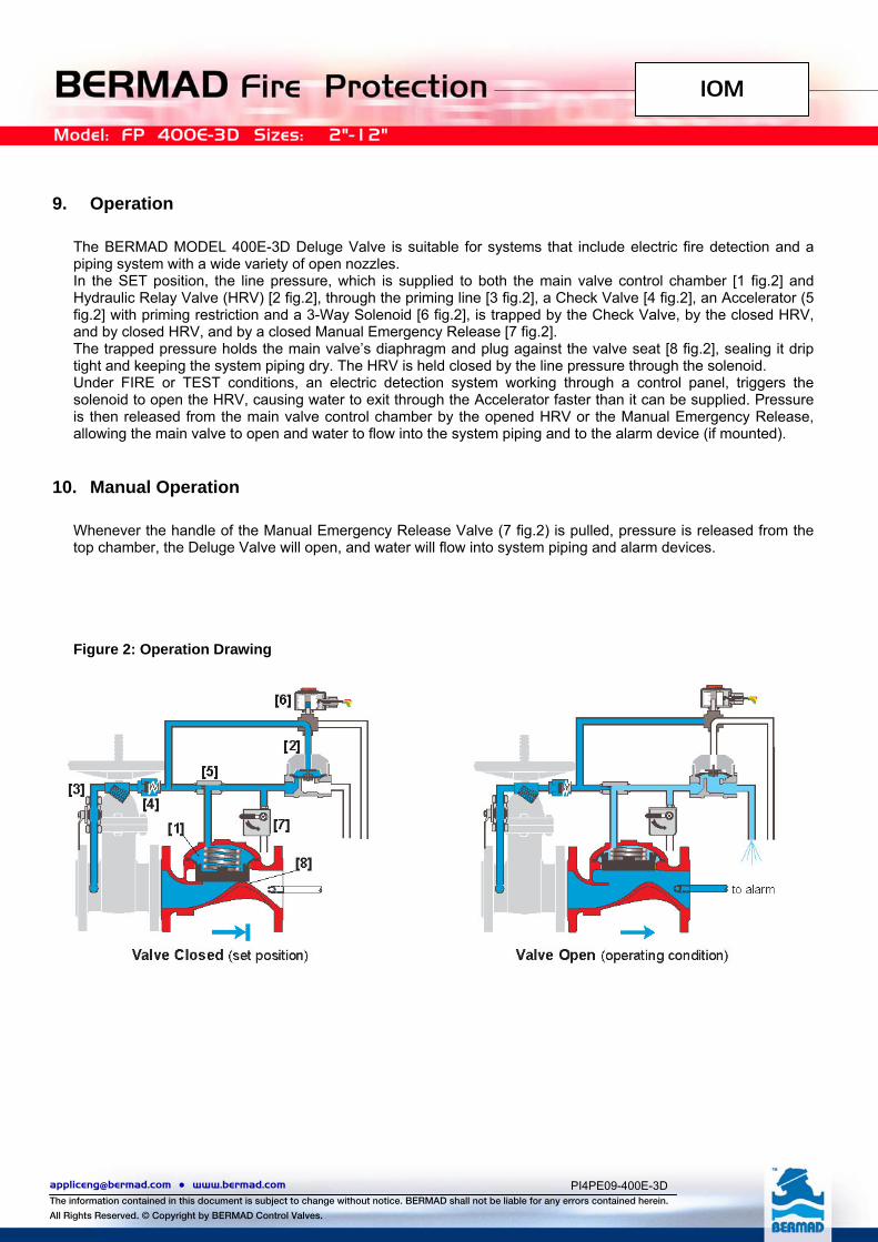
9. Operation
The BERMAD MODEL 400E-3D Deluge Valve is suitable for systems that include electric fire detection and a piping system with a wide variety of open nozzles. In the SET position, the line pressure, which is supplied to both the main valve control chamber [1 fig.2] and Hydraulic Relay Valve (HRV) [2 fig.2], through the priming line [3 fig.2], a Check Valve [4 fig.2], an Accelerator (5 fig.2] with priming restriction and a 3-Way Solenoid [6 fig.2], is trapped by the Check Valve, by the closed HRV, and by closed HRV, and by a closed Manual Emergency Release [7 fig.2]. The trapped pressure holds the main valve’s diaphragm and plug against the valve seat [8 fig.2], sealing it drip tight and keeping the system piping dry. The HRV is held closed by the line pressure through the solenoid. Under FIRE or TEST conditions, an electric detection system working through a control panel, triggers the solenoid to open the HRV, causing water to exit through the Accelerator faster than it can be supplied. Pressure is then released from the main valve control chamber by the opened HRV or the Manual Emergency Release, allowing the main valve to open and water to flow into the system piping and to the alarm device (if mounted).
10. Manual Operation
Whenever the handle of the Manual Emergency Release Valve (7 fig.2) is pulled, pressure is released from the top chamber, the Deluge Valve will open, and water will flow into system piping and alarm devices. Figure 2: Operation Drawing
[email protected] ● www.bermad.com The information contained in this document is subject to change without notice. BERMAD shall not be liable for any errors contained herein.
All Rights Reserved. © Copyright by BERMAD Control Valves.
IOM
Model: FP 400E-3D Sizes: 2"-12"
PI4PE09-400E-3D
11. Maintenance and Inspection Test
Warning: Do not turn off the water supply to make repairs without placing a roving fire patrol in the area covered by the system. The patrol should continue until the system is back in service. 11.1 Prior to turning off any valves or activating any alarms, notify local security guards and the central alarm
station, if used, so that a false alarm will not be signaled. 11.2 In any of the following inspections or testing procedures, if an abnormal condition exists, see Abnormal
Conditions (§17) for possible cause and corrective action. 11.3 See NFPA Pamphlet No.25.
12. Normal Conditions
12.1 All main Isolating Valves are OPEN. 12.2 All Cock Valves are in the OPEN position. 12.3 The Upstream Pressure Gauge should reflect the upstream supply pressure to the Deluge Valve. 12.4 The Downstream Pressure Gauge should reflect the downstream pressure on the system side of from
the Deluge Valve. 12.5 The Control Panel and Detectors are in service. The electric Solenoid Valve (6 fig.2) is energized and the
coil is slightly warm.
13. Weekly Inspection
13.1 The system should be checked for normal condition. 13.2 Observe the Upstream Pressure Gauge: it should indicate that the normal supply of water pressure to the
Deluge Valve is maintained. 13.3 Observe that there is no leaking from the Deluge Valve to the nozzles.
14. Monthly Inspection and Test
14.1 Complete Weekly Inspection (§14). 14.2 Test the Deluge Valve’s operation by de-energizing the supply current to the Solenoid Valve (6 fig.2). 14.3 The Deluge Valve, Trim, Auxiliary Devices and Manual Release must be activated at full flow.
Note: The system will be flooded! Take all necessary precautions to drain water and prevent damage in the area protected by the Deluge system.
15. Annual Inspection and Test
15.1 Complete Weekly and Monthly inspections (§14 & 15). 15.2 Place the system out of service (See instructions in §8). 15.3 Trip the Release-Line System, clean all strainers (4b fig.1), and Priming-Line Restriction (5 fig.2). 15.4 The interior of the Deluge Valve should be inspected and cleaned. 15.5 The interior of the HRV, including its Diaphragm and Seal, should be inspected and cleaned 15.6 Place the system back in service. (See instructions "Placing the System in Service" see §7). 15.7 The Deluge Valve, Trim, Auxiliary Devices and Manual Release must be activated at full flow. 15.8 Note: The system will be flooded! Take all necessary precautions to drain water and prevent damage
the area protected by the Deluge system.
[email protected] ● www.bermad.com The information contained in this document is subject to change without notice. BERMAD shall not be liable for any errors contained herein.
All Rights Reserved. © Copyright by BERMAD Control Valves.
IOM
Model: FP 400E-3D Sizes: 2"-12"
PI4PE09-400E-3D
15.9 Trip test the Deluge System with an Electric Release Control Panel. The release may be tripped by the method suggested by the Release Control Panel manufacturer. Reset the system.
15.10 The Manual Emergency Valve Release Handle (7 fig.2) is to be pulled and tested. The Deluge Valve should open and discharge water.
15.11 Observe pressure on the upstream Pressure Gauge while full flow is on. Inspect all nozzles in the system. Take all additional measures as required by NFPA 25 "Standard for the Inspection, Testing and Maintenance of Water-Based Fire Protection Systems."
16. Abnormal Conditions
16.1 Alarm Pressure Switch Fails to Sound A. Clean the Alarm-Line. B. Test the electrical circuit to the Pressure Switch (PS) (if utilized). C. Observe if the Pressure Switch Cock Valve is open.
16.2 False Trip Check for any of the following possible causes:
A. Electrical malfunctioning of the Control System or Electric Panel. B. HRV is out of order. C. Solenoid Valve (6 fig.2) is out of order.
16.3 Leakage Through Deluge Valve Check for any of the following possible causes:
A. Partially plugged Priming Restriction (2b fig.1). B. Plugged Priming Strainer (4b fig.1). C. Leaking Release System. D. Damaged Deluge Valve seat or a foreign object is caught inside the seat. E. HRV out of order. F. Solenoid Valve (24b fig.1) out of order.
16.4 Deluge Valve Will Not Reset Check for any of the following possible causes:
A. Closed Priming Cock Valve (3 fig.2). B. Damaged Deluge Valve seat a foreign object is caught inside the seat. C. Foreign object lodged between seal disc and valve seat. D. HRV out of order. E. Solenoid Valve (6 fig.2) out of order.
16.5 Electric Release System Will Not Reset A. Faulty Detector Circuit B. Faulty circuit to the Solenoid Valve (6 fig.2) or Release Control Panel. C. Observe if the Pressure Switch Cock Valve is open.
16.6 Difficulty in Performance Where difficulty in performance is experienced, the manufacturer or his authorized representative should be contacted if any field adjustment is to be made.