bermad irrigation · 1099 855 450 450 740 320 370 820 467 740 358 386 1099 870 iso pn 10 ; 16 iso...
TRANSCRIPT

BERMAD IrrigationTechnical Specifications
Available Sizes & PatternsDN 40 - DN 500 - Y PatternDN 40 - DN 450 - AngleDN 600 - DN 800 - Globe
Connection StandardFlanged: ISO 7005-2 (ISO 10, 16 & 25)Threaded: BSP (Rp ISO 7/1) or NPT (DN 40 - DN 80)
Water TemperatureUp to 80ºC
Working pressureISO PN 16: 16 barISO PN 25: 25 bar
Standard Materials❑ Main valve body and cover
Ductile Iron to EN 1563❑ Main valve internals
Stainless Steel, Bronze & Epoxy coated Steel❑ Control Trim
Brass, Bronze accessoriesStainless Steel 316 fittings & tubingor forged Brass fittings & Copper tubing
❑ ElastomersNBR
❑ CoatingBlue fusion bonded Epoxy
Optional Materials❑ Main valve body and cover
Carbon Steel to EN 10083-1Stainless Steel 316 to EN 10088-1Nickel Aluminum Bronze to BS-EN 1400 AB-2Other materials on request
❑ Control TrimStainless Steel 316, Nickel Aluminum Bronze,Hastalloy C-276 accessoriesMonel fittings & tubing
❑ ElastomersEPDMFPM
Available Sizes & PatternsDN 40 - DN 500 - Y PatternDN 40 - DN 450 - Angle
Connection StandardFlanged: ISO 7005-1(ISO 10, 16, 25 & 40)
Water TemperatureUp to 80ºC
Working pressureISO PN 16: 16 barISO PN 25: 25 barISO PN 40: 40 bar
Standard Materials❑ Main valve body
Carbon Steel to EN 10083-1❑ Valve cover (piston cylinder)
Stainless Steel or Bronze❑ Main valve internals
Stainless Steel and Bronze❑ Control Trim
Brass, Bronze accessoriesStainless Steel 316 fittings & tubingor forged Brass fittings & copper tubing
❑ ElastomersNBR
❑ CoatingBlue fusion bonded Epoxy
Optional Materials❑ Main valve body and Cover
Ductile Iron to EN 1563Stainless Steel 316 to EN 10088-1Nickel Aluminum Bronze to BS-EN 1400 AB-2Other materials on request
❑ Control TrimStainless Steel 316, Nickel Aluminum Bronze,Hastalloy C-276 accessoriesMonel fittings & tubing
❑ ElastomersEPDMFPM
SI 700 Metric SI 800 Metric
The information herein is subject to change without notice. BERMAD shall not be held liable forany errors. All rights reserved. © Copyright by BERMAD. PC7XE01-04 05
i n f o @ b e r m a d . c o m • w w w . b e r m a d . c o m
WW-700 & 800 Series

BERMAD IrrigationDimensions & Weights
Angle Pattern
W
H
h
LR
4012415578852279.5124165788522711
50124155838522710124165858522711.5
6514917895109251121491859510925113.5
8015220010010228121.515920710510928723
1001902221151273423520025012713535041
1502253201431524417123432015916545481
200265390172203545118277390191216558138
250320480204219633205336480223236649233
300396550248273777350415550261294796390
350400550264279781370419550293299801425
40045074029936910828004677403253861099855
45045074032037010828204677403583861099870
ISO
PN 10
; 16
ISO
PN 20
; 25
mmLWRhH
Weight (Kg)LWRhH
Weight (Kg)
Angle Pattern
H
LR
h
W
501211224083
2255.5
65140122481022427
801591635511529415
BSP
; NPT
mmLWRhH
Weight (Kg)
Threaded
Flanged
Y Pattern
H
h
L
W
40205155782399.12051557823910
502101658324410.62101658324412.2
6522217895257132221859525715
802502001003052226420710531425
1003202231153663733525012737843
1504153201434927543332015950885
200500390172584125524390191602146
250605480204724217637480223742245
300725550242840370762550261859410
350733550268866381767570295893434
400990740300110884610247403251133900
4501000740319112794510307403571165967
5001100740358116796211367503891197986
ISO
PN 10
; 16
ISO
PN 20
; 25
mmLWhH
Weight (Kg)LWhH
Weight (Kg)
SI 700 Metric
Length according to EN 558-1
W
L
H
h
Globe Pattern 60014501250470
1965325015001250470
19653500
70016501250490198537001650125049019853700
75017501250520201539001750125052020153900
80018501250553204841001850125055320484100
ISO
PN 10
; 16
ISO
PN 20
; 25
mmLWhH
Weight (Kg)LWhH
Weight (Kg)
Y Pattern
L
W
H
BSP
; NPT
h
40155122
402015.5
50155122
402025.5
65212122
482098
80250163
5626417
mmLW
hH
Weight (Kg)
Y Pattern - Length according to EN 558-1DNLWhH
Weight (Kg)LWhH
Weight (Kg)
5023016582.52449.723016582.52449.7
803102001003052131020010030521
1003502351183693135023511836931
1504803201505007048032015050070
200600390180592115600390180592115
250730480213733198730480213733198
300850550243841337850550243841337
The information herein is subject to change without notice. BERMAD shall not be held liable forany errors. All rights reserved. © Copyright by BERMAD. PC7XE01-06 05
i n f o @ b e r m a d . c o m • w w w . b e r m a d . c o m
WW-700 Series

BERMAD IrrigationDimensions & Weights
Flanged
Y Pattern
H
h
L
W
5023016582.52449.723016582.52449.7
803102001003052131020010030521
1003502351183693135023511836931
1504803201505007048032015050070
200600390180592115600390180592115
250730480213733198730480213733198
300850550243841337850550243841337
PN
10;
16
PN
25
DNL*WhH
Weight (Kg)L*WhH
Weight (Kg)
Angle Pattern
W
H
h
LR
4012415578852279.5124165788522711
50124155838522710124165858522711.5
6514917895109251121491859510925113.5
8015220010010228121.515920710510928723
1001902221151273423520025012713535041
1502253201431524417123432015916545481
200265390172203545118277390191216558138
250320480204219633205336480223236649233
300396550248273777350415550261294796390
350400550264279781370419550293299801425
40045074029936910828004677403253861099855
45045074032037010828204677403583861099870
PN
10
; 16
PN
25
DNLWRhH
Weight (Kg)LWRhH
Weight (Kg)
Angle Pattern
H
LR
h
W
5012112240832255.5
65140122481022427
801591635511529415
BS
P ;
NP
T
DNLWRhH
Weight (Kg)
Y Pattern
L
W
H
Threaded
BS
P ;
NP
T
DNLW
hH
Weight (Kg)
h
40155122
402015.5
50155122
402025.5
65212122
482098
80250163
5626417
* Length according to EN 558-1.
W
L
H
h
G Pattern 60014501250470
1965325015001250470
19653500
70016501250490198537001650125049019853700
75017501250520201539001750125052020153900
80018501250553204841001850125055320484100
PN
10
; 16
PN
25
DNL*WhH
Weight (Kg)LWhH
Weight (Kg)
40205155782399.12051557823910
6522219095257132221909525715
350733550268866381767570295893434
400990740300110884610247403251133900
4501000740319112794510307403571165967
5001100740358116796211367503891197986
DNLWhH
Weight (Kg)LWhH
Weight (Kg)
502101658324410.62101658324412.2
802502001003052226421010531425
1003202291153663733525412737843
1504153201434927543332015950885
200500390172584125524390191602146
250605480204724217637480223742245
300725550242840370762550261859410
On request (Y Pattern)
* Length according to EN 558-1for DN 50, 80, 100, 150, 200, 250 & 300.
SI 700 Metric European Standard (EN 558-1)
The information herein is subject to change without notice. BERMAD shall not be held liable forany errors. All rights reserved. © Copyright by BERMAD. PC7XE01-08 05
i n f o @ b e r m a d . c o m • w w w . b e r m a d . c o m
WW-700 Series
BERMAD Irrigation
The information herein is subject to change without notice. BERMAD shall not be held liable forany errors. All rights reserved. © Copyright by BERMAD. PC7XE01-07 05
i n f o @ b e r m a d . c o m • w w w . b e r m a d . c o m
Dimensions & Weights
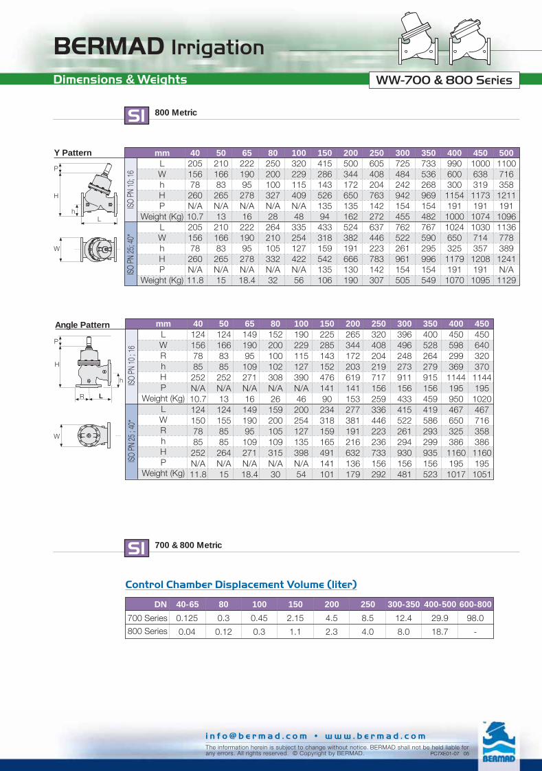
0.125 0.3 0.45 2.15 4.5 8.5 12.4 29.9 98.0
0.04 0.12 0.3 1.1 2.3 4.0 8.0 18.7 -
SI 700 & 800 Metric
Control Chamber Displacement Volume (liter)
DN 40-65 80 100 150 200 250 300-350 400-500 600-800
700 Series
800 Series
Angle Pattern 401241567885
252N/A10.71241507885
252N/A11.8
501241668385252N/A131241558585264N/A15
6514919095109271N/A1614919095109271N/A18.4
80152200100102308N/A26159200105109315N/A30
100190229115127390N/A46200254127135398N/A54
15022528514315247614190234318159165491141101
200265344172203619141153277381191216632136179
250320408204219717156259336446223236733156292
300396496248273911156433415522261294930156481
350400528264279915156459419586293299935156523
400450598299369114419595046765032538611601951017
4504506403203701144195102046771635838611601951051
ISO
PN 10
; 16
ISO
PN 25
; 40*
mmLWRhHP
Weight (Kg)LWRhHP
Weight (Kg)
W
P
H
h
LR
SI 800 Metric
Y Pattern
L
ISO
PN 10
; 16
ISO
PN 25
; 40*
4020515678260N/A10.720515678260N/A11.8
5021016683265N/A1321016683265N/A15
6522219095278N/A1622219095278N/A18.4
80250200100327N/A28264210105332N/A32
100320229115409N/A48335254127422N/A56
15041528614352613594433318159542135106
200500344172650135162524382191666130190
250605408204763142272637446223783142307
300725484242942154455762522261961154505
350733536268969154482767590295996154549
40099060030011541911000102465032511791911070
450100063831911731911074103071435712081911095
50011007163581211191109611367783891241N/A
1129
H
h
P
W
mmLWhHP
Weight (Kg)LWhHP
Weight (Kg)
WW-700 & 800 Series

BERMAD Irrigation
The information herein is subject to change without notice. BERMAD shall not be held liable forany errors. All rights reserved. © Copyright by BERMAD.
i n f o @ b e r m a d . c o m • w w w . b e r m a d . c o m
Flow Charts
SI Metric
Y Pattern, Throttling Plug (U-Type)
Flow Rate - m3/h (Water)
Pre
ssur
e Lo
ss -
bar
0.05
0.1
1.0
10 100 1,000 10,000
0.5
50 500 5,000
500
40 65
50
80 100 150 200 250 300 350 450
400
Y Pattern, Flat Disk
Pre
ssur
e Lo
ss -
bar 500
100 150 200 250 300 350 450 600 700750800400
65
50
8040
Flow Rate - m3/h (Water)
0.1
1.0
10 100 1,000 10,000
0.5
50 500 5,000
0.05
WW-700 & 800 Series

BERMAD Irrigation
The information herein is subject to change without notice. BERMAD shall not be held liable forany errors. All rights reserved. © Copyright by BERMAD. PC7XE01-11 05
i n f o @ b e r m a d . c o m • w w w . b e r m a d . c o m
WW-700 & 800 SeriesFlow Charts
Angle Pattern, Throttling Plug (U-Type)
SI Metric
Pre
ssur
e Lo
ss -
bar
0.05
0.1
1.0
10 100 1,000 10,000
0.5
50 500 5,000
65
50
250 300 350 450
400
40 80 100 150 200
Flow Rate - m3/h (Water)
Angle Pattern, Flat Disk
Pre
ssur
e Lo
ss -
bar
0.05
65
50
80 100 150 200 250 300 350 450
400
40
0.1
1.0
10 100 1,000 10,000
0.5
50 500 5,000Flow Rate - m3/h (Water)

BERMAD IrrigationFlow Properties
mm 600 700 750 800Kv 7,350 7,500 7,500 7,500K 3.8 6.7 8.8 11.4Leq - m 188.0 390.1 550.9 760.7
G-PatternFlat Disk
SI Metric
mm 40 50 65 80 100 150 200 250 300 350 400 450 500Kv 42 50 55 115 200 460 815 1,250 1,850 1,990 3,310 3,430 3,550K 2.3 3.9 9.2 4.9 3.9 3.7 3.8 3.9 3.7 5.9 3.7 5.5 7.8Leq - m 4.3 10.3 33.4 21.6 23.0 37.5 53.9 70.0 85.6 159.9 112.7 204.8 323.8Kv 36 43 47 98 170 391 693 1,063 1,573 1,692 2,814 2,916 3,018K 3.1 5.4 12.8 6.7 5.4 5.2 5.2 5.4 5.1 8.2 5.1 7.6 10.8Leq - m 6.0 14.3 46.2 29.9 31.9 51.9 74.6 96.8 118.4 221.3 155.9 283.5 448.1Kv 46 55 61 127 220 506 897 1,375 2,035 2,189 3,641 3,773 NAK 1.9 3.2 7.6 4.0 3.2 3.1 3.1 3.2 3.1 4.9 3.0 4.5 NALeq - m 3.6 8.5 27.6 17.8 19.0 31.0 44.6 57.8 70.7 132.1 93.1 169.3 NAKv 39 47 51 108 187 430 762 1,169 1,730 1,861 3,095 3,207 NAK 2.6 4.5 10.6 5.6 4.5 4.3 4.3 4.5 4.2 6.8 4.2 6.2 NALeq - m 5.0 11.8 38.2 24.7 26.4 42.9 61.7 80.0 97.9 182.9 128.9 234.3 NA
Y-PatternFlat Disk
Y-PatternU-Plug
Angle PatternFlat Disk
Angle PatternU-Plug
SI Metric
Where:Kv = Valve flow coefficient (flow in m3/h at 1bar Diff. Press.)Cv = Valve flow coefficient (flow in gpm at Diff. Press. 1psi)Q = Flow rate (m3/h ; gpm)∆P = Differential pressure (bar ; psi)Gf = Liquid specific gravity (Water = 1.0)
Valve flow coefficient, Kv or Cv Kv(Cv)=Q Gf
∆P
Cv = 1.155 Kv
Where:K = Flow resistance or Head loss coefficient (dimensionless)∆H = Head loss (m ; feet)V = Nominal size flow velocity (m/sec ; feet/sec.)g = Acceleration of gravity (9.81 m/sec2 ; 32.18 feet/sec2)
K = ∆H2gV2
Flow resistance or Head loss coefficient,
Equivalent Pipe Length, Leq
Where:Leq= Equivalent nominal pipe length (m ; feet)Lk = Equivalent length coefficient for turbulent flow in clean
commercial steel pipe (SCH 40)D = Nominal pipe diameter (m ; feet)
Note:The Leq values given are for general consideration only.Actual Leq may vary somewhat with each of the valve sizes.
Leq = Lk·D
The information herein is subject to change without notice. BERMAD shall not be held liable forany errors. All rights reserved. © Copyright by BERMAD. PC7XE01-15 05
i n f o @ b e r m a d . c o m • w w w . b e r m a d . c o m
WW-700 & 800 Series

BERMAD Irrigation
The information herein is subject to change without notice. BERMAD shall not be held liable forany errors. All rights reserved. © Copyright by BERMAD. PC7XE01-13 05
i n f o @ b e r m a d . c o m • w w w . b e r m a d . c o m
Cavitation
SI Metric
The cavitation phenomenon has a significant affect on controlvalve and system performance.Cavitation may damage the valve and piping by the affectsof erosion and vibration. Cavitation also generates noise andmay limit and ultimately choke the flow.As the pressure differential across the valve increases, thestatic pressure of the flow passing through the throttling areaof the valve (Vena Contracta) drops sharply.When the fluid's static pressure reaches liquid vapor pressure,vapor cavities (bubbles) form and grow until they violentlyimplode by the recovered pressure downstream to the valveseat.The implosion of these cavities generates high-pressuresurges, micro jets and intensive heat, which erode valvecomponents and downstream piping. In its final stage,cavitation flashes and chokes the flow.The above Cavitation Guides for Bermad 700 Series valvesare based on the formula commonly used in the valve industry:
= (P2-Pv) / (P1-P2)
Where:
= Sigma, cavitation index, dimensionlessP1 = Upstream pressure, absoluteP2 = Downstream pressure, absolutePv = Liquid vapor pressure, absolute
(Water, 18ºC = 0.02 bar-a) ; 65ºF = 0.3 psi-a)
Use these guides and your applications upstream anddownstream pressures to determine whether their intersectionlies in or out of the cavitation damage zone.Considerations to avoid cavitation damage:A) Reduce system pressure in stages designing each pressure
stage to be above cavitation conditions.B) Consider using other valve selection criteria
a. Valve body and plug typeb. Valve sizec. Valve material
Notes:1. An alternate cavitation index formula introduced by ISA is:
ISA = (P1-Pv) / (P1-P2) which equals +12. The above charts should be considered only as a general
guide.3. For optimum system and control valve application please
consult Bermad.
Cavitation
Cavitation Guide
Upstream pressure - bar
Do
wns
trea
m p
ress
ure
- b
ar
CavitationDamage Zone
Flat Disk
V-Port Plug
8
7
6
5
4
3
2
1
00 2 4 6 8 10 12 14 16 18 20 22 24
WW-700 & 800 Series

BERMAD Irrigation
Available Sizes & Patterns11/2” - 20” - Y Pattern11/2” - 18” - Angle24” - 32” - Globe
Connection StandardFlanged: ANSI B16.42 (Ductile Iron)Threaded: NPT or BSP (11/2” -3”)
Water TemperatureUp to 180ºF
Working pressureClass #150: 250 psiClass #300: 400 psi
Standard Materials❑ Main valve body and cover
Ductile Iron to ASTM A-536❑ Main valve internals
Stainless Steel, Bronze & Epoxy coated Steel❑ Control Trim
Brass, Bronze accessoriesStainless Steel 316 fittings & tubingor forged Brass fittings & Copper tubing
❑ ElastomersNBR
❑ CoatingBlue fusion bonded Epoxy
Optional Materials❑ Main valve body and cover
Carbon Steel to ASTM A-216-WCBStainless Steel 316 to ASTM A-743 CF8MNickel Aluminum Bronze to ASTM B-148 C 95800Other materials on request
❑ Control TrimStainless Steel 316, Nickel Aluminum Bronze,Hastalloy C-276 accessoriesMonel fittings & tubing
❑ ElastomersEPDMFPM
Available Sizes & Patterns11/2” - 20” - Y Pattern11/2” - 18” - Angle
Connection StandardFlanged: ANSI B16.5 (Cast steel)
Water TemperatureUp to 180ºF
Working pressureClass #150: 250 psiClass #300: 400 psiClass #400: 600 psi
Standard Materials❑ Main valve body
Carbon Steel to ASTM A-216-WCB❑ Valve cover (piston cylinder)
Stainless Steel or Bronze❑ Main valve internals
Stainless Steel and Bronze❑ Control Trim
Brass, Bronze accessoriesStainless Steel 316 fittings & tubingor forged Brass fittings & Copper tubing
❑ ElastomersNBR
❑ CoatingBlue fusion bonded Epoxy
Optional Materials❑ Main valve body and Cover
Ductile Iron to ASTM A-536Stainless Steel 316 to ASTM A-743 CF8MNickel Aluminum Bronze to ASTM B-148 C 95800Other materials on request
❑ Control TrimStainless Steel 316, Nickel Aluminum Bronze,Hastalloy C-276 accessoriesMonel fittings & tubing
❑ ElastomersEPDMFPM
US 700 English US 800 English
Technical Specifications
The information herein is subject to change without notice. BERMAD shall not be held liable forany errors. All rights reserved. © Copyright by BERMAD. PC7XE01-05 05
i n f o @ b e r m a d . c o m • w w w . b e r m a d . c o m
WW-700 & 800 Series

BERMAD IrrigationDimensions & Weights
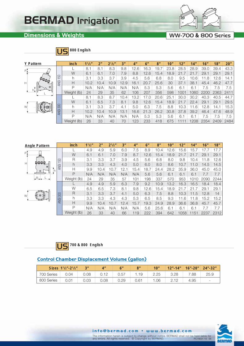
US 700 English
Flanged
Y Pattern 11/2”8.16.13.19.4208.16.13.19.422
2”8.16.13.39.6238.36.53.39.627
21/2”8.37.03.710.1298.77.33.710.133
3”9.87.93.912.049
10.48.14.112.455
4”12.68.84.514.482
13.29.85.014.995
6”16.312.65.619.416517.012.66.320.0187
8”19.715.46.823.027620.615.47.523.7322
10”23.818.98.028.547825.118.98.829.2540
12”28.521.79.533.181630.021.710.333.8904
14”28.921.710.634.184030.222.411.635.2957
16”39.029.111.843.6186540.329.112.844.61984
18”39.429.112.644.4208340.529.114.145.92132
20”43.329.114.145.9212144.729.515.347.12174
ANSI
125 ;
150
ANSI
250 ;
300
inchLWhH
Weight (lb)LWhH
Weight (lb)
H
h
L
W
W
L
H
h
Globe Pattern 24”5749
18.577
71505949
18.577
7700
28”65491978
814065491978
8140
30”7049
20.579.385807049
20.579.38580
32”7349
21.880.690207349
21.880.69020
ANSI
125 ;
150
ANSI
250 ;
300
inchLWhH
Weight (lb)LWhH
Weight (lb)
Threaded
Angle Pattern 11/2”4.96.13.13.38.9214.96.53.13.38.924
2”4.96.13.33.38.9224.96.53.33.38.925
21/2”5.97.03.74.39.9275.97.33.74.39.930
3”6.07.93.94.011.1476.38.14.14.311.351
4”7.58.74.55.013.5777.99.85.05.313.890
6”8.912.65.66.017.41579.212.66.36.517.9179
8”10.415.46.88.021.526010.915.47.58.522.0304
10”12.618.98.08.624.945213.218.98.89.325.6514
12”15.621.79.810.730.677216.321.710.311.631.3860
14”15.721.710.411.030.781616.521.711.511.831.5937
16”17.729.111.814.542.6176418.429.112.815.243.31885
18”17.729.112.614.542.6180818.429.114
15.243.31918
ANSI
125 ;
150
ANSI
250 ;
300
inchLWRhH
Weight (lb)LWRhH
Weight (lb)W
H
h
LR
Angle Pattern 2”4.84.81.63.38.912
21/2”5.54.81.94.09.515
3”6.36.42.24.511.633
BSP
; NPT
inchLWRhH
Weight (lb)
H
LR
h
W
Y Pattern 11/2”6.14.8
1.67.912
2”6.14.8
1.68.012
21/2”8.34.8
8.28.218
3”9.86.4
2.210.437
BSP
; NPT
inchLW
hH
Weight (lb)L
W
H
h
The information herein is subject to change without notice. BERMAD shall not be held liable forany errors. All rights reserved. © Copyright by BERMAD. PC7XE01-09 05
i n f o @ b e r m a d . c o m • w w w . b e r m a d . c o m
WW-700 Series
BERMAD Irrigation
US 800 English
Y Pattern
L
ANSI
150
ANSI
300
11/2”8.16.13.1
10.2N/A248.16.13.1
10.2N/A26
2”8.16.13.310.4N/A298.36.53.310.4N/A33
21/2”8.37.03.710.9N/A358.77.33.710.9N/A40
3”9.87.93.912.9N/A62
10.48.14.113.1N/A70
4”12.68.84.516.1N/A10613.29.85.016.6N/A123
6”16.312.65.620.75.320717.012.66.321.35.3233
8”19.715.46.825.65.335620.615.47.526.25.3418
10”23.818.98.0305.659825.118.98.830.85.6675
12”28.521.79.537.16.1
100130.021.710.337.86.1
1111
14”28.921.710.638.16.1
106030.222.411.639.26.1
1208
16”39.029.111.845.47.5
220040.329.112.846.47.5
2354
18”39.429.112.646.27.5
236340.529.114.147.67.5
2409
20”43.329.114.147.77.5
241144.729.515.348.97.5
2484
inchLWhHP
Weight (lb)LWhHP
Weight (lb)
H
h
P
W
Angle Pattern 11/2”4.96.13.13.39.9N/A244.96.53.13.39.9N/A26
2”4.96.13.33.310.4N/A294.96.53.33.310.4N/A33
21/2”5.97.03.74.310.7N/A355.97.33.74.310.7N/A40
3”6.07.93.94.012.1N/A576.38.14.14.312.4N/A66
4”7.58.74.55.015.4N/A1017.99.85.05.315.7N/A119
6”8.912.65.66.018.75.61989.212.66.36.519.35.6222
8”10.415.46.88.024.45.633710.915.47.58.524.925.6394
10”12.618.98.08.628.26.157013.218.98.89.328.96.1642
12”15.621.79.810.735.96.195316.321.710.311.636.66.1
1058
14”15.721.710.411.036.06.1
101016.521.711.511.836.86.1
1151
16”17.729.111.814.545.07.7
209018.429.112.815.245.77.7
2237
18”17.729.112.614.545.07.7
224418.429.114
15.245.77.7
2312
ANSI
150
ANSI
300
inchLWRhHP
Weight (lb)LWRhHP
Weight (lb)
W
P
H
h
LR
US 700 & 800 English
Control Chamber Displacement Volume (gallon)
Sizes 11/2”-21/2” 3” 4” 6” 8” 10” 12”-14” 16”-20” 24”-32”
0.04 0.08 0.12 0.57 1.19 2.25 3.28 7.88 25.9
0.01 0.03 0.08 0.29 0.61 1.06 2.12 4.95 -
700 Series
800 Series
Dimensions & Weights
The information herein is subject to change without notice. BERMAD shall not be held liable forany errors. All rights reserved. © Copyright by BERMAD. PC7XE01-10 05
i n f o @ b e r m a d . c o m • w w w . b e r m a d . c o m
WW-700 & 800 Series

BERMAD Irrigation
Y Pattern, Throttling Plug (U-Type)
1
10
15
5
Pre
ssur
e Lo
ss -
psi
10 100 1,000 10,000 100,00050 500 5,000 50,000
3” 4” 6” 8” 18”
12”
11/2”
2”
21/2”
14”
16”
20”
10”
Flow Rate - gpm (Water)
US English
Y Pattern, Flat Disk
1
10
15
5
Pre
ssur
e Lo
ss -
psi
10 100 1,000 10,000 100,00050 500 5,000 50,000
10”
24”
3” 4” 6” 8” 18”
12”
11/2”
2”
21/2”
14”
16”
20”
28”30”32”
Flow Rate - gpm (Water)
The information herein is subject to change without notice. BERMAD shall not be held liable forany errors. All rights reserved. © Copyright by BERMAD.
i n f o @ b e r m a d . c o m • w w w . b e r m a d . c o m
Flow Charts WW-700 & 800 Series

BERMAD Irrigation
Angle Pattern, Flat Disk
1
10
15
5
Pre
ssur
e Lo
ss -
psi
10 100 1,000 10,000 100,00050 500 5,000 50,000
12”
3” 4” 6” 8” 18”11/2”
2”
21/2”
14”
16”10”
Flow Rate - gpm (Water)
US English
Angle Pattern, Throttling Plug (U-Type)
1
10
15
5
Pre
ssur
e Lo
ss -
psi
10 100 1,000 10,000 100,00050 500 5,000 50,000
3” 4” 6” 8” 18”
12”
11/2”
2”
21/2”
14”
16”10”
Flow Rate - gpm (Water)
Flow Charts
The information herein is subject to change without notice. BERMAD shall not be held liable forany errors. All rights reserved. © Copyright by BERMAD. PC7XE01-12 05
i n f o @ b e r m a d . c o m • w w w . b e r m a d . c o m
WW-700 & 800 Series

BERMAD Irrigation
The information herein is subject to change without notice. BERMAD shall not be held liable forany errors. All rights reserved. © Copyright by BERMAD. PC7XE01-16 05
i n f o @ b e r m a d . c o m • w w w . b e r m a d . c o m
Flow Properties
US English
inch 1.5" 2" 2.5" 3" 4" 6" 8" 10" 12" 14" 16" 18" 20"Cv 49 58 64 133 230 530 940 1,440 2,140 2,300 3,820 3,960 4,100K 2.3 3.9 9.2 4.9 3.9 3.7 3.8 3.9 3.7 5.9 3.7 5.5 7.8Leq-feet 14.2 33.8 109.5 70.8 75.6 123.0 176.9 229.5 280.8 524.5 369.6 671.9 1,062.3Cv 41 49 54 113 200 450 800 1,230 1,820 1,950 3,250 3,370 3,490K 3.1 5.4 12.8 6.7 5.4 5.2 5.2 5.4 5.1 8.2 5.1 7.6 10.8Leq-feet 19.7 46.8 151.6 97.9 104.6 170.2 244.8 317.6 388.6 725.9 511.6 930.0 1,470.3Cv 53 64 70 146 250 580 1,040 1,590 2,350 2,530 4,210 4,360 NAK 1.9 3.2 7.6 4.0 3.2 3.1 3.1 3.2 3.1 4.9 3.0 4.5 NALeq-feet 11.7 28.0 90.5 58.5 62.5 101.6 146.2 189.7 232.0 433.4 305.5 555.3 NACv 45 54 59 124 220 500 880 1,350 2,000 2,150 3,580 3,710 NAK 2.6 4.5 10.6 5.6 4.5 4.3 4.3 4.5 4.2 6.8 4.2 6.2 NALeq-feet 16.3 38.7 125.3 80.9 86.5 140.7 202.4 262.5 321.2 599.9 422.8 768.6 NA
Y-PatternFlat Disk
Y-PatternU-Plug
Angle PatternFlat Disk
Angle PatternU-Plug
Where:Kv = Valve flow coefficient (flow in m3/h at 1bar Diff. Press.)Cv = Valve flow coefficient (flow in gpm at Diff. Press. 1psi)Q = Flow rate (m3/h ; gpm)∆P = Differential pressure (bar ; psi)Gf = Liquid specific gravity (Water = 1.0)
Valve flow coefficient, Kv or Cv Kv(Cv)=Q Gf
∆P
Cv = 1.155 Kv
Where:K = Flow resistance or Head loss coefficient (dimensionless)∆H = Head loss (m ; feet)V = Nominal size flow velocity (m/sec ; feet/sec.)g = Acceleration of gravity (9.81 m/sec2 ; 32.18 feet/sec2)
K = ∆H2gV2
Flow resistance or Head loss coefficient,
Equivalent Pipe Length, Leq
Where:Leq= Equivalent nominal pipe length (m ; feet)Lk = Equivalent length coefficient for turbulent flow in clean
commercial steel pipe (SCH 40)D = Nominal pipe diameter (m ; feet)
Note:The Leq values given are for general consideration only.Actual Leq may vary somewhat with each of the valve sizes.
Leq = Lk·D
inch 24" 28" 30" 32"Cv 8,490 8,670 8,670 8,670K 3.8 6.7 8.8 11.4Leq-feet 616.6 1,280.0 1,807.3 2,495.6
G-PatternFlat Disk
EnglishUS
WW-700 & 800 Series

BERMAD Irrigation
The information herein is subject to change without notice. BERMAD shall not be held liable forany errors. All rights reserved. © Copyright by BERMAD. PC7XE01-14 05
i n f o @ b e r m a d . c o m • w w w . b e r m a d . c o m
The cavitation phenomenon has a significant affect on controlvalve and system performance.Cavitation may damage the valve and piping by the affectsof erosion and vibration. Cavitation also generates noise andmay limit and ultimately choke the flow.As the pressure differential across the valve increases, thestatic pressure of the flow passing through the throttling areaof the valve (Vena Contracta) drops sharply.When the fluid's static pressure reaches liquid vapor pressure,vapor cavities (bubbles) form and grow until they violentlyimplode by the recovered pressure downstream to the valveseat.The implosion of these cavities generates high-pressuresurges, micro jets and intensive heat, which erode valvecomponents and downstream piping. In its final stage,cavitation flashes and chokes the flow.The above Cavitation Guides for Bermad 700 Series valvesare based on the formula commonly used in the valve industry:
= (P2-Pv) / (P1-P2)
Where:
= Sigma, cavitation index, dimensionlessP1 = Upstream pressure, absoluteP2 = Downstream pressure, absolutePv = Liquid vapor pressure, absolute
(Water, 18ºC = 0.02 bar-a) ; 65ºF = 0.3 psi-a)
Use these guides and your applications upstream anddownstream pressures to determine whether their intersectionlies in or out of the cavitation damage zone.Considerations to avoid cavitation damage:A) Reduce system pressure in stages designing each pressure
stage to be above cavitation conditions.B) Consider using other valve selection criteria
a. Valve body and plug typeb. Valve sizec. Valve material
Notes:1. An alternate cavitation index formula introduced by ISA is:
ISA = (P1-Pv) / (P1-P2) which equals +12. The above charts should be considered only as a general
guide.3. For optimum system and control valve application please
consult Bermad.
Cavitation
USCavitation Guide
Upstream pressure - psi
Do
wn
str
eam
pre
ssu
re -
psi
120
100
80
60
40
30
20
10
0
110
90
70
50
CavitationDamage Zone
Flat Disk
V-Port Plug
0 30 60 90 120 150 180 210 240 270 300 330 360
English
Cavitation WW-700 & 800 Series

BERMAD Irrigation
For spare parts ordering, Please use BERMAD “Spare Parts Ordering Guide”
Lifting eye nut
Cover bolt & disk
Indicator nutShaft nut
Diaphragm washer
Diaphragm
Spacer disk
Shaft
Cover nut & disk
Spring
O-ring
Seal disk
Seal disk nut
Shaft locking screwSeal
Seal disk washer
Seat screw
SeatValve body
Control boss
Drain
Cover plug
O-ring
Cover
Bearing screw
V-Port throttling plug (U-shape) - option
Control boss
Bearing diskO-ring
Bearing
O-rings
Diaphragm washer
Separating partition
Lifting eye bolt
Stud
Seal disk screws
Nut & disk
700 Valve - Exploded View
The information herein is subject to change without notice. BERMAD shall not be held liable forany errors. All rights reserved. © Copyright by BERMAD.
i n f o @ b e r m a d . c o m • w w w . b e r m a d . c o m
WW-700 Series

For spare parts ordering, Please use BERMAD “Spare Parts Ordering Guide”
Lifting eye nut
Cover bolt
Indicator nut
Shaft nut
O-ring
Seal disk
Seal disk nut
Shaft locking screw
Seal
Seal disk washer
Seat screw
SeatValve body
Controlboss
Drain
Cover plug
O-ring
Cover / Cylinder
Bearing screws
V-Port throttling plug (U-shape) - option
Control boss
Bearing
Separating partition
Seal disk screws
Nut & disk
Lifting eye bolt
O-rings
O-ring
DiskPiston seal
Piston
Shaft
BERMAD Irrigation
The information herein is subject to change without notice. BERMAD shall not be held liable forany errors. All rights reserved. © Copyright by BERMAD. PC7XE01-02 05
i n f o @ b e r m a d . c o m • w w w . b e r m a d . c o m
800 Valve - Exploded View WW-800 Series

BERMAD IrrigationPressure Rating
Standard Operation Pressure – Materials Data
End Connections Standards / Pressure Ratings / Materials / Max. Operating Pressure
+ Available, Not required by the standard pressure class– Not available
* External flange diameter might vary then the standard.Can be used in 800 series only.
BermadCode
10 or E116 or E625 or E5
40A5A3A4BDBHJ1J6J2J3B1B6B2
BPPHNPNH
EndConnections
Standard
I S OI S OI S OI S O
A N S IA N S IA N S IBS 10BS 10J I SJ I SJ I SJ I S
A B N TA B N TA B N TThreads
B S P (Rp ISO 7/1)B S P (Rp ISO 7/1)
N P TN P T
PressureClass
PN 10PN 16PN 25
PN 40 *# 150# 300
# 400 *Table DTable H
10 K16 K20 K
30 K *101625
Nickel aluminumbronze to
ASTM B-148 C 95800or BS-EN 1400 AB-2
+16 bar25 bar
–250 psi400 psi
–+
400 psi+
27 bar28 bar
–+
16 bar25 bar
25 bar
400 psi
Ductile iron toASTM A-536or EN 1563
++
25 bar–
250 psi400 psi
–+
400 psi+
27 bar28 bar
–++
25 bar
25 bar
400 psi
Carbon steel toASTM A-216-WCB
or EN 10083-1
++
25 bar40 bar285 psi400 psi600 psi
+400 psi
+27 bar28 bar40 bar
++
25 bar
25 bar
400 psi
Stainless steel 316to ASTM A-743 CF8M
or EN 10088-1
++
25 bar40 bar285 psi400 psi600 psi
+400 psi
+27 bar28 bar40 bar
++
25 bar
25 bar
400 psi
The information herein is subject to change without notice. BERMAD shall not be held liable forany errors. All rights reserved. © Copyright by BERMAD. PC7XE01-03 05
i n f o @ b e r m a d . c o m • w w w . b e r m a d . c o m
WW-700 & 800 Series

BERMAD Irrigation
Flo
w -
m3 /
h
Typical Pressure Reducing Performance ChartActual Hydraulic Laboratory Results
15
14
13
12
11
10
9
8
7
6
5
4
3
2
1
00 100 200 300 400 500 600 700 800 900 1,000 1,100 1,200
700
600
500
400
300
200
100
0
Time - sec
Pre
ssur
e -
bar Upstream Press.
Flow Rate
Downstream Press.
Valve Plugs CharacteristicsKv ; Cv to Valve Opening Chart
Kv ; Cv %
Valv
e Tr
avel
%
0
10
20
30
40
50
60
70
80
90
100
0 10 20 30 40 50 60 70 80 90 100
Flat Disk
V-Port Plug (U
-Shape)
The information herein is subject to change without notice. BERMAD shall not be held liable forany errors. All rights reserved. © Copyright by BERMAD. PC7XE01-17 05
i n f o @ b e r m a d . c o m • w w w . b e r m a d . c o m
WW-700 & 800 Series