beresford t 9 n - south dakota department of transportation · - meet requirements of astm f894 and...
TRANSCRIPT
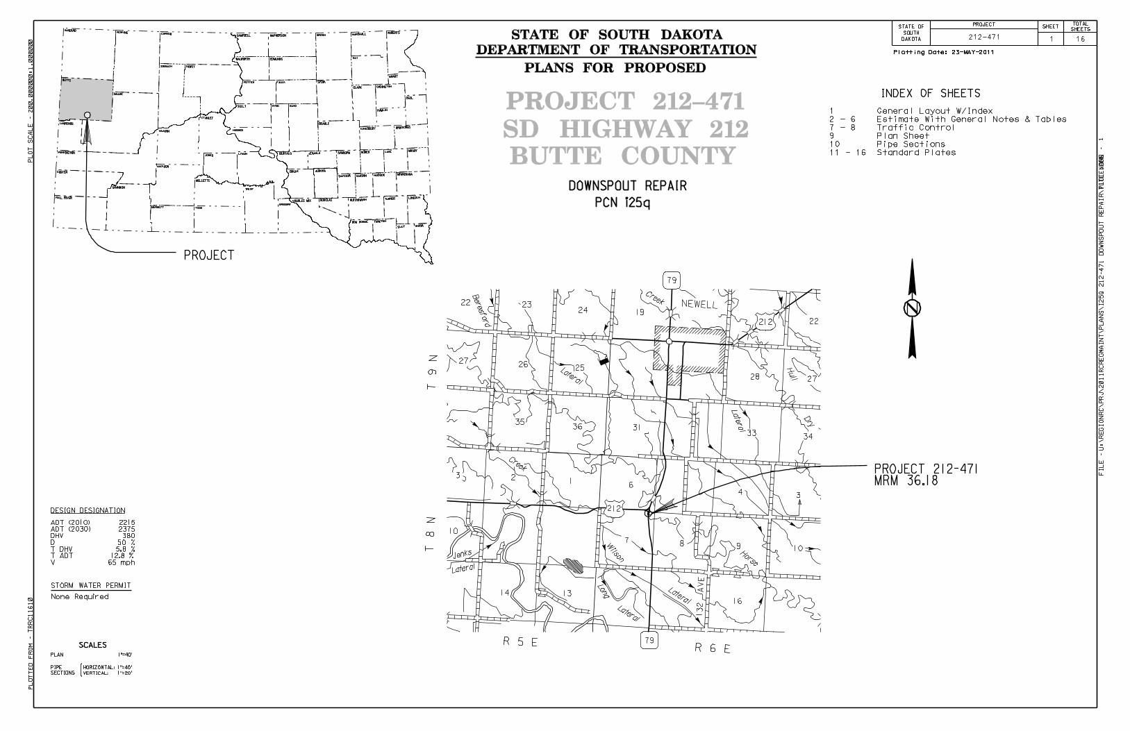
STATE OF SOUTH DAKOTA
DEPARTMENT OF TRANSPORTATION
PLANS FOR PROPOSED
SD HIGHWAY 212
BUTTE COUNTY
PROJECT 212-471
PROJECTSTATE OF
SOUTH
DAKOTA
TOTAL
SHEETS
SHEET
PROJECT
UNION
TURNER
HANSON
BRULE
BEADLE
SULLY
FAULK SPINK
CLARK
GRANT
DAY
WALWORTH
BROWN
PERKINS
LAWRENCE
PENNINGTON
STANLEY
JONES
GREGORY
MELLETTE
TODD
SHANNON
PCN i25q
23-MAY-2011Plotting Date:
1 16212-471
STORM WATER PERMIT
SCALES
SECTIONS {
PLAN
HORIZONTAL:
VERTICAL:
CLAY
BON HOMME YANKTON
CHARLES MIX
DOUGLAS
HUTCHINSON LINCOLN
MINNEHAHAMcCOOKDAVISON
AURORA
BUFFALO
JERAULD
SANBORN
MINER MOODY
BROOKINGS
KINGSBURY
HAND
HUGHES
POTTER
CODINGTON
HAMLIN
DEUL
EDMUNDS
CAMPBELL
McPHERSON
MARSHALL ROBERTS
HARDING CORSON
ZIEBACH
DEWEY
MEADE
BUTTE
LYMAN
TRIPP
CUSTER
FALL RIVER
trrc1
16
10
200.0
0000
1
Plotted F
rom
-
Plot S
cale -
File - U
:\regionR
C\
Plot N
am
e -
LAKE
HYDE
HAAKON
JACKSON
BENNETT
DOWNSPOUT REPAIR
10
1
10
19
22
2728
3133
34
34
6
78 9
16
22 2324
2526
27
3536
23
1314
NEWELL
212
212
132 A
VE
Dry
Horse
Creek
Lateral
Jenks
Lateral
Wilson
Long
Lateral
Bere
sfo
rd
Lateral
Late
ral
Creek
Hull
R 5 ER 6 E
T 8
NT
9 N
79
79
PROJECT 212-471
MRM 36.18
INDEX OF SHEETS
None Required
ADT (2010)
ADT (2030)
DHV
D
T DHV
V
T ADT
2215
2375
380
50 %
5.8 %
12.8 %
65 mph
DESIGN DESIGNATION
1"=40’
1"=20’
PIPE
1"=40’
1 General Layout W/Index
2 - 6 Estimate With General Notes & Tables
7 - 8 Traffic Control
9 Plan Sheet
10 Pipe Sections
11 - 16 Standard Plates
PROJECT STATE OF SOUTH
DAKOTA 212-471
SHEET
2 16
TOTAL SHEETS
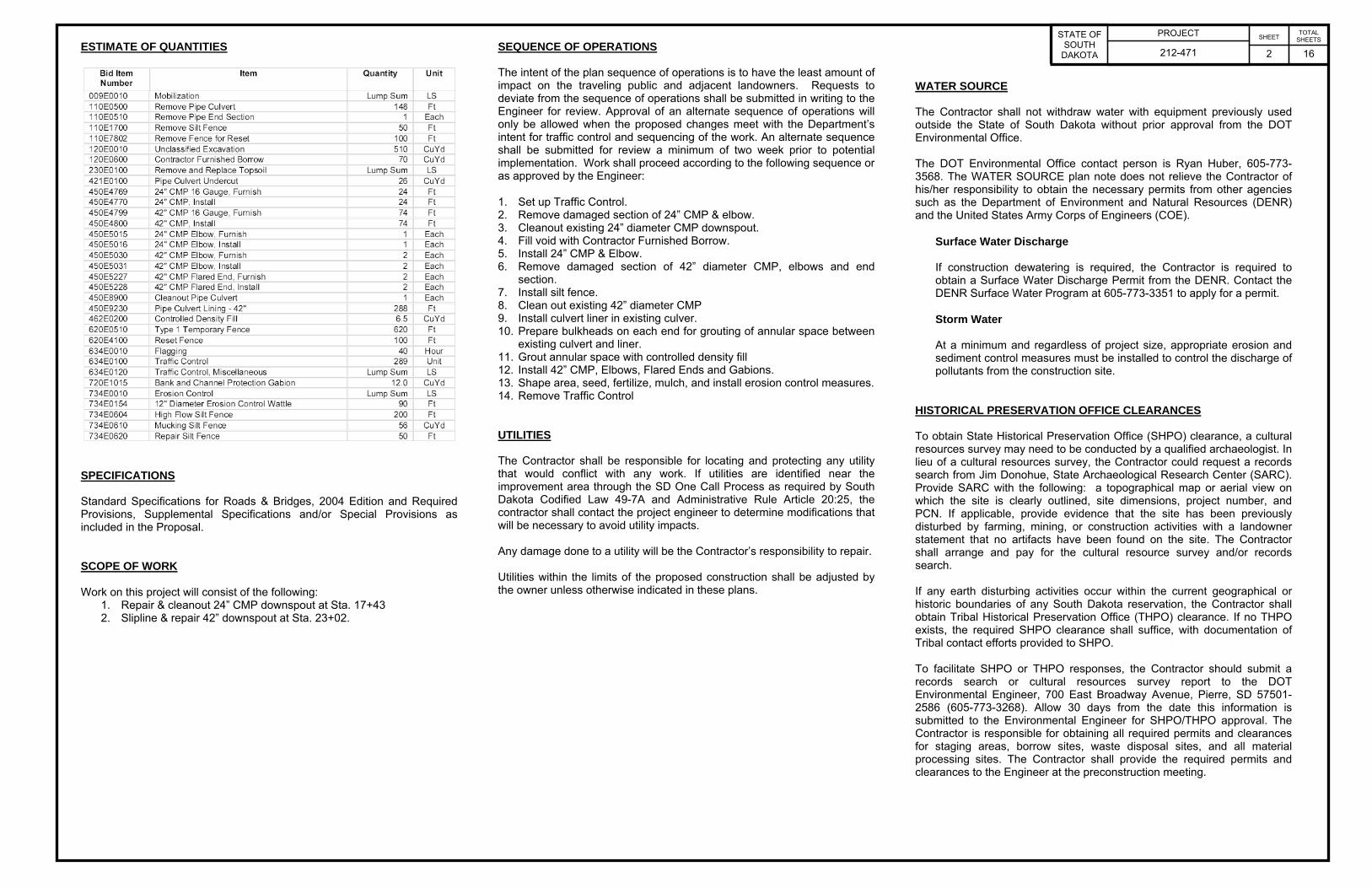
ESTIMATE OF QUANTITIES
SPECIFICATIONS Standard Specifications for Roads & Bridges, 2004 Edition and Required Provisions, Supplemental Specifications and/or Special Provisions as included in the Proposal. SCOPE OF WORK Work on this project will consist of the following:
1. Repair & cleanout 24” CMP downspout at Sta. 17+43 2. Slipline & repair 42” downspout at Sta. 23+02.
SEQUENCE OF OPERATIONS The intent of the plan sequence of operations is to have the least amount of impact on the traveling public and adjacent landowners. Requests to deviate from the sequence of operations shall be submitted in writing to the Engineer for review. Approval of an alternate sequence of operations will only be allowed when the proposed changes meet with the Department’s intent for traffic control and sequencing of the work. An alternate sequence shall be submitted for review a minimum of two week prior to potential implementation. Work shall proceed according to the following sequence or as approved by the Engineer: 1. Set up Traffic Control. 2. Remove damaged section of 24” CMP & elbow. 3. Cleanout existing 24” diameter CMP downspout. 4. Fill void with Contractor Furnished Borrow. 5. Install 24” CMP & Elbow. 6. Remove damaged section of 42” diameter CMP, elbows and end
section. 7. Install silt fence. 8. Clean out existing 42” diameter CMP 9. Install culvert liner in existing culver. 10. Prepare bulkheads on each end for grouting of annular space between
existing culvert and liner. 11. Grout annular space with controlled density fill 12. Install 42” CMP, Elbows, Flared Ends and Gabions. 13. Shape area, seed, fertilize, mulch, and install erosion control measures. 14. Remove Traffic Control UTILITIES The Contractor shall be responsible for locating and protecting any utility that would conflict with any work. If utilities are identified near the improvement area through the SD One Call Process as required by South Dakota Codified Law 49-7A and Administrative Rule Article 20:25, the contractor shall contact the project engineer to determine modifications that will be necessary to avoid utility impacts. Any damage done to a utility will be the Contractor’s responsibility to repair. Utilities within the limits of the proposed construction shall be adjusted by the owner unless otherwise indicated in these plans.
WATER SOURCE The Contractor shall not withdraw water with equipment previously used outside the State of South Dakota without prior approval from the DOT Environmental Office. The DOT Environmental Office contact person is Ryan Huber, 605-773-3568. The WATER SOURCE plan note does not relieve the Contractor of his/her responsibility to obtain the necessary permits from other agencies such as the Department of Environment and Natural Resources (DENR) and the United States Army Corps of Engineers (COE).
Surface Water Discharge If construction dewatering is required, the Contractor is required to obtain a Surface Water Discharge Permit from the DENR. Contact the DENR Surface Water Program at 605-773-3351 to apply for a permit.
Storm Water
At a minimum and regardless of project size, appropriate erosion and sediment control measures must be installed to control the discharge of pollutants from the construction site.
HISTORICAL PRESERVATION OFFICE CLEARANCES To obtain State Historical Preservation Office (SHPO) clearance, a cultural resources survey may need to be conducted by a qualified archaeologist. In lieu of a cultural resources survey, the Contractor could request a records search from Jim Donohue, State Archaeological Research Center (SARC). Provide SARC with the following: a topographical map or aerial view on which the site is clearly outlined, site dimensions, project number, and PCN. If applicable, provide evidence that the site has been previously disturbed by farming, mining, or construction activities with a landowner statement that no artifacts have been found on the site. The Contractor shall arrange and pay for the cultural resource survey and/or records search. If any earth disturbing activities occur within the current geographical or historic boundaries of any South Dakota reservation, the Contractor shall obtain Tribal Historical Preservation Office (THPO) clearance. If no THPO exists, the required SHPO clearance shall suffice, with documentation of Tribal contact efforts provided to SHPO. To facilitate SHPO or THPO responses, the Contractor should submit a records search or cultural resources survey report to the DOT Environmental Engineer, 700 East Broadway Avenue, Pierre, SD 57501-2586 (605-773-3268). Allow 30 days from the date this information is submitted to the Environmental Engineer for SHPO/THPO approval. The Contractor is responsible for obtaining all required permits and clearances for staging areas, borrow sites, waste disposal sites, and all material processing sites. The Contractor shall provide the required permits and clearances to the Engineer at the preconstruction meeting.

PROJECT STATE OF SOUTH
DAKOTA 212-471
SHEET
3 16
TOTAL SHEETS
WASTE DISPOSAL SITE The Contractor will be required to furnish a site(s) for the disposal of construction/demolition debris generated by this project. Construction/demolition debris may not be disposed of within the State ROW. The waste disposal site(s) shall be managed and reclaimed in accordance with the following from the General Permit for Highway, Road, and Railway Construction/Demolition Debris Disposal Under the South Dakota Waste Management Program issued by the Department of Environment and Natural Resources. The waste disposal site(s) shall not be located in a wetland, within 200 feet of surface water, or in an area that adversely affects wildlife, recreation, aesthetic value of an area, or any threatened or endangered species, as approved by the Engineer. If the waste disposal site(s) is located such that it is within view of any ROW, the following additional requirements shall apply: 1. Construction/demolition debris consisting of concrete, asphalt
concrete, or other similar materials shall be buried in a trench completely separate from wood debris. The final cover over the construction/demolition debris shall consist of a minimum of 1 foot of soil capable of supporting vegetation. Waste disposal sites provided outside of the State ROW shall be seeded in accordance with Natural Resources Conservation Service recommendations. The seeding recommendations may be obtained through the appropriate County NRCS Office. The Contractor shall control the access to waste disposal sites not within the State ROW through the use of fences, gates, and placement of a sign or signs at the entrance to the site stating “No Dumping Allowed”.
2. Concrete and asphalt concrete debris may be stockpiled within
view of the ROW for a period of time not to exceed the duration of the project. Prior to project completion, the waste shall be removed from view of the ROW or buried and the waste disposal site reclaimed as noted above.
The above requirements will not apply to waste disposal sites that are covered by an individual solid waste permit as specified in SDCL 34A-6-58, SDCL 34A-6-1.13, and ARSD 74:27:10:06. Failure to comply with the requirements stated above may result in civil penalties in accordance with South Dakota Solid Waste Law, SDCL 34A-6-1.31. All costs associated with furnishing waste disposal site(s), disposing of waste, maintaining control of access (fence, gates, and signs), and reclamation of the waste disposal site(s) shall be incidental to the various contract items.
CORRUGATED METAL PIPE Corrugated metal pipes shall have 2 ⅔-inch X ½-inch corrugations for 42-inch and smaller round pipe and 48-inch and smaller arch pipe unless otherwise stated in the plans. Corrugated metal pipes shall have 3-inch X 1-inch or 5-inch X 1-inch corrugations for 48-inch and larger round pipe and 54-inch and larger arch pipe unless otherwise stated in the plans. PIPE CONNECTIONS When it is not possible to use a normal pipe joint (male-female ends), connections to existing pipe shall be made by placing a 2’ wide by 6" thick M6 concrete collar around the outside of the connection. The concrete collar shall be reinforced with 6x6 W2.9 x W2.9 wire mesh. All costs for constructing the concrete collars including materials and labor shall be incidental to the contract unit price per foot for the corresponding pipe bid item. CLEAN PIPE CULVERT This work shall consist of cleaning out, removing and disposing of the earth and debris within the existing culvert. The existing culvert 17+43 is a 24” diameter CMP x 186’ downspout. Cleaning method shall be approved by the Engineer. The culvert shall be cleaned to the satisfaction of the Engineer. The Contractor shall be responsible for repairing any damage caused by the cleaning process. All earth and debris removed from the culvert shall be disposed of outside the existing right-of-way. The Contractor shall shape the area of the culvert ends to restore flow. All costs associated with cleaning out the existing culvert, the removal of debris and shaping of the outlet area shall be incidental to the contract unit price per each for “Cleanout Pipe Culvert”.
SLIPLINE PIPE The Contractor shall furnish and install slipliner pipe at locations specified in the Table of Slipline Pipe. This work consists of slipping high density polyethylene (HDPE) or PVC pipe liner inside existing inplace pipe and grouting the void between the liner and the existing pipe. Slipliner pipe shall conform to one of the following material types. 1. Closed Profile HDPE: - Meet requirements of ASTM F894 and ASTM D3350 with cell classification 345464C. Minimum pipe stiffness shall be 46 psi in accordance with ASTM D2412. - Pipe joints shall be threaded and approved by the Engineer. 2. Solid Wall HDPE: - Meet requirements of ASTM F714 (SDR 32.5) and ASTM D3350 with cell classification 345464C. - Pipe joints may be grooved press-on joints or heat fused with heat fusion equipment as approved by the Engineer. Heat fused joints shall follow recommendations of the pipe manufacturer and use an experienced operator of the heat fusion equipment. 3. PVC: - Meet requirements of ASTM F949 with minimum pipe stiffness of 46 psi, and ASTM D1784 with minimum cell classification 12454B. - Pipe joints shall be elastomeric sealing gaskets meeting requirements of ASTM F477. 4. Spirally Wound PVC: - Meet requirements of ASTM F949 with minimum pipe stiffness of 46 psi. - Pipe joints shall be per pipe manufacturer’s recommendations and approved by the Engineer. Slipliner pipe shall have a smooth interior surface. Slipliner pipe shall be joined into a continuous length with joints that are adequate for pushing, pulling or winding the liner pipe though the existing pipe. The joints shall be watertight to prevent seepage during pressure grouting. The joints should not create an increase in the outside diameter of the liner pipe to allow a more smooth insertion of the liner. The diameter specified in the bid item is the diameter of the existing pipe to be sliplined. The slipliner pipe size to use within the existing pipe size is provided in the following slipliner pipe dimension table unless otherwise specified. This provides the largest diameter liner pipe that will fit into the existing pipe to maximize flow capacity.

PROJECT STATE OF SOUTH
DAKOTA 212-471
SHEET
4 16
TOTAL SHEETS
SLIPLINE PIPE (Cont.) Slipliner Pipe Dimension Table
Existing
Pipe I.D.
(inch)
Closed Profile HDPE O.D. (inch)
Closed Profile HDPE
I.D. (inch)
Solid Wall
HDPE O.D. (inch)
Solid Wall
HDPE I.D.
(inch)
PVC O.D. (inch)
PVC I.D.
(inch)
Spirally Wound PVC O.D. (inch)
Spirally Wound PVC I.D.
(inch) 24 20.24 18.00 22.00 20.65 22.60 20.70 20.45 20.00 30 27.06 24.00 28.00 26.29 25.60 23.50 27.45 27.00 36 33.82 30.00 32.00 30.03 32.20 29.50 32.79 32.00 42 40.65 36.00 40.00 36.95 38.70 35.50 38.79 38.00 48 45.20 40.00 42.00 39.42 42.79 42.00 54 47.47 42.00 48.00 44.33 48.79 48.00 60 54.00 50.68 54.79 54.00
Prior to sliplining, the Contractor shall clean the existing pipe of all debris, silt, obstructions, etc. in order to ensure that the liner can be inserted, the grout will flow to all voids and the inserted liner will not be resting on or irregularly supported by such material. Cleaning shall be accomplished by the use of jet rodding equipment or other approved methods. Silt fence shall be used to catch any sediment. The slipliner pipe shall be inserted into the existing pipe by pushing, pulling or winding methods that do not damage the slipliner pipe. The slipliner pipe shall be clean and substantially dry before insertion. Pressure grouting shall be done to ensure all the voids are filled between the liner pipe and existing pipe including all breaks or holes in and around the existing pipe. Grouting pressures used shall ensure all voids are filled, but do not collapse the slipliner pipe. The Contractor shall provide a pressure gauge that will measure the grouting pressure and a means to accurately measure the volume of grout injected. Slipliner pipe shall be held down to minimize the change in flowline, especially at the inlet end. This may be accomplished by attaching fasteners or blocks at the top of the pipe, adding weight to the invert, placing multiple grout lifts, or other means to prevent the slipliner from floating during the grouting operation. Grout at the inlet end shall be finished with a 45 degree mitered bevel transition between the existing pipe and the inside of the slipliner pipe with the slipliner pipe face pushed inside the existing pipe face. If grout holes are utilized, cylindrical wooden plugs or other approved plugs shall be inserted to plug holes until the grout has set and then removed and filled with concrete. The Contractor shall submit the manufacturer’s certificate of compliance for the slipliner pipe used and shall submit the Contractor’s proposed procedure for sliplining pipes including the grouting procedure to the Engineer at least two weeks prior to beginning this work. Controlled density fill material shall be used as the flowable grout. The quantity of Controlled density fill is estimated based on using a Closed Profile HDPE and estimating the void volume outside the existing pipe. All costs for furnishing and installing the slipliner pipe, including work area excavation and backfilling, pipe cleaning, and incidentals necessary to satisfactorily complete the work shall be incidental to the contract unit price per foot for the corresponding diameter bid item for “Slipline 42” Pipe”.
SLIPLINE PIPE (Cont.) All costs for furnishing and installing the controlled density fill, including method to prevent slipliner from floating, inlet bevel construction, and incidentals necessary to satisfactorily complete the work shall be incidental to the contract unit price per cubic yard for “Controlled Density Fill”. TABLE OF SLIPLINE PIPE Location
Slipline 42” Pipe
(Ft)
Controlled Density
Fill (CuYd)
23+02 288 6.5
Total: 288 6.5 CONSTRUCTION REQUIREMENTS The liners shall be unloaded from the truck delivering them to the project by using slings and boom-type trucks or the equivalent. Chains or wire rope will not be permitted for handling. A winch truck or other equipment may be required to install the liner. CONTROLLED DENSITY FILL FOR PIPE Controlled density fill shall be a flowable mortar material. Materials shall be in accordance with the Standard Specifications, except as modified below. The mix design shall be the following:
Material Rate per Cubic Yard Portland Cement, Type II 100 Lb Fine Aggregate 2600 Lb Coarse Aggregate None Water 60 Gal Fly Ash, Type C 300 Lb
The fine aggregate shall be natural sand consisting of mineral aggregate particles conforming to the following gradation requirements: Passing 3/8 Inch Sieve 100% Passing No. 200 Sieve 0-10% The mix design shown above is designed to produce a minimum compressive strength of 100 psi. The Engineer may allow adjustments to the proportion of water at the site to provide the necessary consistency of the mix. The quantity of Controlled Density Fill is estimated based on using a Closed Profile HDPE and estimating the void volume outside the existing pipe. All costs for furnishing and installing the Controlled Density Fill, including method to prevent pipe liner from floating, inlet bevel construction, and incidentals necessary to satisfactorily complete the work shall be incidental to the contract unit price per cubic yard for “Controlled Density Fill”.
EXCAVATION FOR PIPE REMOVAL Included in the quantity of “Unclassified Excavation” are 510 cubic yards of excavation for removal of pipes. All work necessary to excavate and backfill the pipes including labor, equipment, and incidentals shall be incidental to the contract unit price per cubic yard for “Unclassified Excavation”. Payment for pipe excavation shall be based only on plans quantity and measurement of these excavation quantities during construction shall not be performed. Station
L/R Quantity (CuYd)
17+43 R 74 23+02 L 111 23+02 R 325
Total: 510 PIPE REMOVAL Removal of CMP Elbows shall be incidental to the contract unit price per foot for “Remove Pipe Culvert”. TABLE OF PIPE CULVERT UNDERCUT The Table of Pipe Culvert Undercut is intended to be used to establish an estimated quantity of Pipe Culvert Undercut for bidding purposes only. The table includes undercut for 36 inch and larger pipe culverts. The depth of undercut is an estimate and the actual depth necessary shall be determined during construction. Pipes shown may or may not require undercutting and pipes not shown may require undercutting. The Engineer will determine which pipe shall be undercut in accordance with Section 421 of the Standard Specifications. Station
Undercut Depth
(Ft)
Quantity (CuYd)
23+02 1 25.7
Total: 25.7 The table contains the rate of pipe culvert undercut per foot of pipe length and should be used as an aid in determining the actual amount of undercut to be performed during construction. The table is derived from the drawing below and conforms to the Standard Specifications. When calculating pipe culvert undercut, the length of pipe ends should be included in the overall pipe length.

PROJECT STATE OF SOUTH
DAKOTA 212-471
SHEET
5 16
TOTAL SHEETS
TABLE OF PIPE CULVERT UNDERCUT(Cont.)
Pipe Diameter
(In)
Round Pipe Undercut Rate
for 1’ Depth (CuYd/Ft)
Arch Pipe Undercut Rate
for 1’ Depth (CuYd/Ft)
24 0.2407 0.2577 30 0.2623 0.2847 36 0.2840 0.3110 42 0.3056 0.3337 48 0.3272 0.3596 54 0.3488 0.3827 60 0.3704 0.4105 66 0.3920 --- 72 0.4136 0.4630 78 0.4352 --- 84 0.4568 0.5123 90 0.4784 ---
CONTRACTOR FURNISHED BORROW The Contractor shall provide a suitable site for Contractor furnished borrow material. The Contractor is responsible for obtaining all required permits and clearances for the borrow site. The borrow material shall be approved by the Engineer. The plans quantity for “Contractor Furnished Borrow” as shown in the Estimate of Quantities will be for filling voids caused by erosion from the existing pipe to the satisfaction of the Engineer at Sta. 17+43. It is the Contractor’s responsibility to inspect and verify the actual field conditions. The Contractor shall be responsible for protecting the utility in the area that is to be filled with Contractor Furnished Borrow. Any damage done to a utility will be the Contractor’s responsibility to repair. Restoration of the Contractor furnished borrow site shall be the responsibility of the Contractor.
TABLE OF BANK AND CHANNEL PROTECTION GABIONS Station
L/R
Quantity (CuYd)
23+02 R 12.0
Total: 12. REMOVE AND REPLACE TOPSOIL Topsoil shall also be salvaged and stockpiled prior to removing the ditch block and placing the embankment at the pipe ends. Limits of this work, depth of salvage, and stockpile location will be directed by the Engineer. Following completion of construction, topsoil shall be spread evenly over the disturbed areas. The estimated amount of topsoil to be removed and replaced is 87 CuYd. All cost associated with removing and replacing the topsoil along areas to be resurfaced shall be incidental to the lump sum price for “Remove and Replace Topsoil”. EROSION CONTROL The contract lump sum price for Erosion Control includes material, equipment, and labor to seed, fertilize and fiber mulching the disturbed areas within the right of way resulting from the work required by this contract. Type F Permanent Seed Mixture shall consist of the following:
Grass Species
Variety
Pure Live Seed (PLS)
(Pounds/Acre) Western Wheatgrass Flintlock, Rodan, Rosana 7 Green Needlegrass Lodorm 4 Sideoats Grama Butte, Killdeer, Pierre, Trailway 3 Blue Grama Bad River, Willis 2 Oats or Spring Wheat: April through May; Winter Wheat: August through November
10
Total: 26 Hand seeding devices approved by the Engineer will be allowed. Following seeding operations, the areas shall be hand raked (incorporated) within the top ¼” to ½” of topsoil when possible to the satisfaction of the Engineer. The areas to be seeded, fertilized, and mulched are estimated at 0.16 acres. Limits of Erosion Control work will be as determined by the Engineer on construction.
FERTILIZING A commercial fertilizer with a minimum guaranteed analysis of 18-46-0, 11-52-0, or an approved alternate fertilizer shall be applied to all areas designated for permanent seeding. The application rate of fertilizer shall be 3 pounds per 1000 SqFt. FIBER MULCHING Fiber mulch shall be applied in a separate operation following permanent seeding. An additional 2% by weight of tackifier shall be added to the fiber mulch product selected from the list below. If the product selected has guar gum tackifier included, then the additional 2% of tackifier shall be guar gum. If the product selected has synthetic tackifier included, then the additional 2% of tackifier shall be synthetic. Fiber mulch shall be applied at the rate of 2000 pounds per acre. The Contractor shall allow the fiber mulch to cure a minimum of 18 hours prior to watering or any storm event to ensure proper cohesion between the soil and fiber particles. All costs for the additional tackifier added to the fiber mulch including labor, equipment, and materials shall be incidental to the lump sum price for “Erosion Control”. The fiber mulch used on this project shall be one from the list below:
Product Manufacturer
Mat-Fiber Plus Mat, Inc. Floodwood, MN Phone: 1-888-477-3028 www.matinc.biz
Conwed Hydro Mulch 2000 Profile Products LLC Buffalo Grove, IL Phone: 1-800-366-1180 www.conwedfibers.com
EcoFibre Plus Tackifier Profile Products LLC Buffalo Grove, IL Phone: 1-800-366-1180 www.profile-eco.com
Terra-Mulch Wood with Tacking Agent 3
Profile Products LLC Buffalo Grove, IL Phone: 1-800-726-6371 www.terra-mulch.com
Excel Fiber Mulch II with Tackifier
American Excelsior Co. Arlington, TX Phone: 1-800-777-7645 www.curlex.com

PROJECT STATE OF SOUTH
DAKOTA 212-471
SHEET
6 16
TOTAL SHEETS
TABLE OF FIBER MULCHING (Quantities Shown for Information Only) Station to
Station
L/R
Quantity (Lb)
82+00 83+60 R 317 82+80 83+20 L 57
Total: 374 EROSION CONTROL WATTLE Erosion control wattles for restraining the flow of runoff and sediment shall be installed at locations noted in the table and at locations determined by the Engineer during construction. Refer to Standard Plate 734.06 for details. The Contractor shall provide certification that the erosion control wattles do not contain noxious weed seeds. The erosion control wattle provided shall be from the list shown below:
Product Manufacturer
Curlex Sediment Log
American Excelsior Company Arlington, TX Phone: 1-800-777-7645 www.amerexcel.com
Aspen Excelsior Logs Western Excelsior Corporation Mancos, CO Phone: 1-800-833-8573 www.westernexcelsior.com
Patriot Wood Fiber Logs
Patriot Environmental Products, Inc. Mesa, AZ Phone: 1-480-345-7293 www.digitaldesigncore.com/patriot/WattleSpecs.pdf
TABLE OF EROSION CONTROL WATTLE Station
L/R
Diameter (Inch)
Location
Quantity (Ft)
17+43 R 12 Slope & Pipe Outlet 30 23+02 R 12 Slope 60
Total: 90
HIGH FLOW SILT FENCE The high flow silt fence fabric provided shall be from the approved product list. The approved product list for high flow silt fence may be viewed at the following internet site: http://apps.sd.gov/Applications/HC54ApprovedProducts/main.asp High flow silt fence shall be placed at the locations noted in the table and at locations that will minimize siltation of adjacent streams, lakes, dams, or drainage areas as determined by the Engineer during construction. Refer to Standard Plate 734.05 for details. TABLE OF HIGH FLOW SILT FENCE Station
L/R
Location
Quantity (Ft)
23+02 L Inlet 100 23+02 R Outlet 100
Total: 200 MUCKING SILT FENCE Mucking silt fence shall consist of removing muck trapped by the silt fence and spreading the material evenly over the adjacent area to conform to the existing grade. REMOVE SILT FENCE Silt fence shall be removed when vegetation is established. Some or all of the silt fence may be left on the project until vegetation is established.

PROJECT STATE OF SOUTH
DAKOTA 212-471
SHEET
7 16
TOTAL SHEETS
GENERAL MAINTENANCE OF TRAFFIC Removing, relocating, covering, salvaging and resetting of permanent traffic control devices, including delineation, shall be the responsibility of the Contractor. Cost for this work shall be incidental to the contract unit prices for the various items unless otherwise specified in the plans. Any delineators and signs damaged or lost shall be replaced by the Contractor at no cost to the State. Storage of vehicles and equipment shall be outside the clear zone and as near as possible to the right-of-way line. Contractor’s employees should mobilize at a location off the right-of-way and arrive at the work sites in a minimum number of vehicles necessary to perform the work. Indiscriminate driving and parking of vehicles within the right-of-way will not be permitted. Any damage to the vegetation, surfacing, embankment, delineators and existing signs resulting from such indiscriminate use shall be repaired and/or restored by the Contractor, at no expense to the State, and to the satisfaction of the Engineer. The bottom of signs on portable or temporary supports shall not be less than seven feet above the pavement in urban areas and one foot above the pavement in rural areas. Portable sign supports may be used as long as the duration is less than 3 days. If the duration is more than 3 days the signs shall be on fixed supports. The Contractor shall provide documentation that all breakaway sign supports comply with FHWA NCHRP 350 or MASH crash-worthy requirements. The Contractor shall provide installation details at the preconstruction meeting for all breakaway sign support assemblies. All vehicles entering and exiting closed lanes of traffic shall display a flashing amber light. Work activities shall only be during daylight hours. Daylight hours are considered to be ½ hour before sunrise until ½ hour after sunset. If the Contractor elects not to work in an area for more than 3 days, for reasons within the control of the Contractor, the Contractor shall remove applicable traffic control devices and replace them when work resumes. There will be no payment for this work. TRAFFIC CONTROL DEVICES INVENTORY
SIGN CODE SIGN SIZE DESCRIPTION NUMBER REQUIRED
UNITS PER SIGN UNITS
G20-2 36'' x 18'' END ROAD WORK 3 17 51W20-1 48'' x 48'' ROAD WORK #### FT. OR AHEAD 3 34 102
W20-7a 48'' x 48'' FLAGGER 2 34 68W21-5 48'' x 48'' SHOULDER WORK 2 34 68
TOTAL UNITS 289

ROAD
WORK
AHEAD
ROAD
WORK
AHEAD
ROAD
WORK
AHEAD
END
ROAD WORK
END
ROAD WORK
END
ROAD WORK
PROJECTSTATE OF
SOUTH
DAKOTA
TOTAL
SHEETS
SHEET
1
4
6
78
9
212
Horse
Wilson
R 5 E
R 6 E
T 8
N
79
FIXED LOCATION SIGNS
W20
-1
W20
-1W
20-1
G20-2A
G20-2A
G20-2A
23-MAY-2011Plotting Date:
trrc1
16
10
200.0
0000
8
Plotted F
rom
-
Plot S
cale -
File - U
:\regionR
C\
Plot N
am
e -
8 16212-471
PROJECT
JUNCTION of US 212 & SD 79
MRM 36.18

20+00
25+00
26+76
2700ft
2700ft
2700ft
2710ft
2710ft2710ft
2720ft
2720ft
PROJECTSTATE OF
SOUTH
DAKOTA
TOTAL
SHEETS
SHEET
23-MAY-2011Plotting Date:
trrc1
16
10
100.0
0000
9
Plotted F
rom
-
Plot S
cale -
File - U
:\regionR
C\
Plot N
am
e -
9 16212-471
23+02
Slipline 42" - 288’ CMP
Install 42" - 74’ CMP (20’, 30’, 6’ & 18’)
And 2 - 20.0^ Elbows
& 2 CMP Flared Ends
17+43 R
Cleanout Pipe 24" Pipe
17+43 - 59.6’ R to 17+43 - 84.0’R
Remove 24" - 24’ CMP
And 1 - Elbow
23+02 149.0’RInstall Bank and Channel
Protection Gabions(12.0 CY)
17+43 - 59.6’ R to 17+43 - 84.0’R
Install 24" - 24’ CMP
And 1 - 20.0^ Elbow
Install High Flow Silt Fence
at the following locations:
23+02 L/R INLET AND OUTLET ENDS OF PIPE (200 FT EACH END)
22+76 R to 23+26 R
Remove & Rest Fence
23+02 - 232.3’ L to 23+02 - 207.2’L
Remove 42" - 20’ CMP
& 1 Flared End
23+02 - 80.7’ R to 23+02 - 166.2’R
Remove 42" - 102’ CMP
17+18 R to 17+68 R
Remove & Rest Fence
at the following locations:
17+43 R 30 FT
23+02 R 60 FT
on slope contour at 30 FT spacing
Install (12") Diameter Erosion Control Wattles
0 320-320
17+43 2680
2690
2700
2710
2720
2730
2740
-
0 320-320
23+02 2680
2690
2700
2710
2720
2730
-
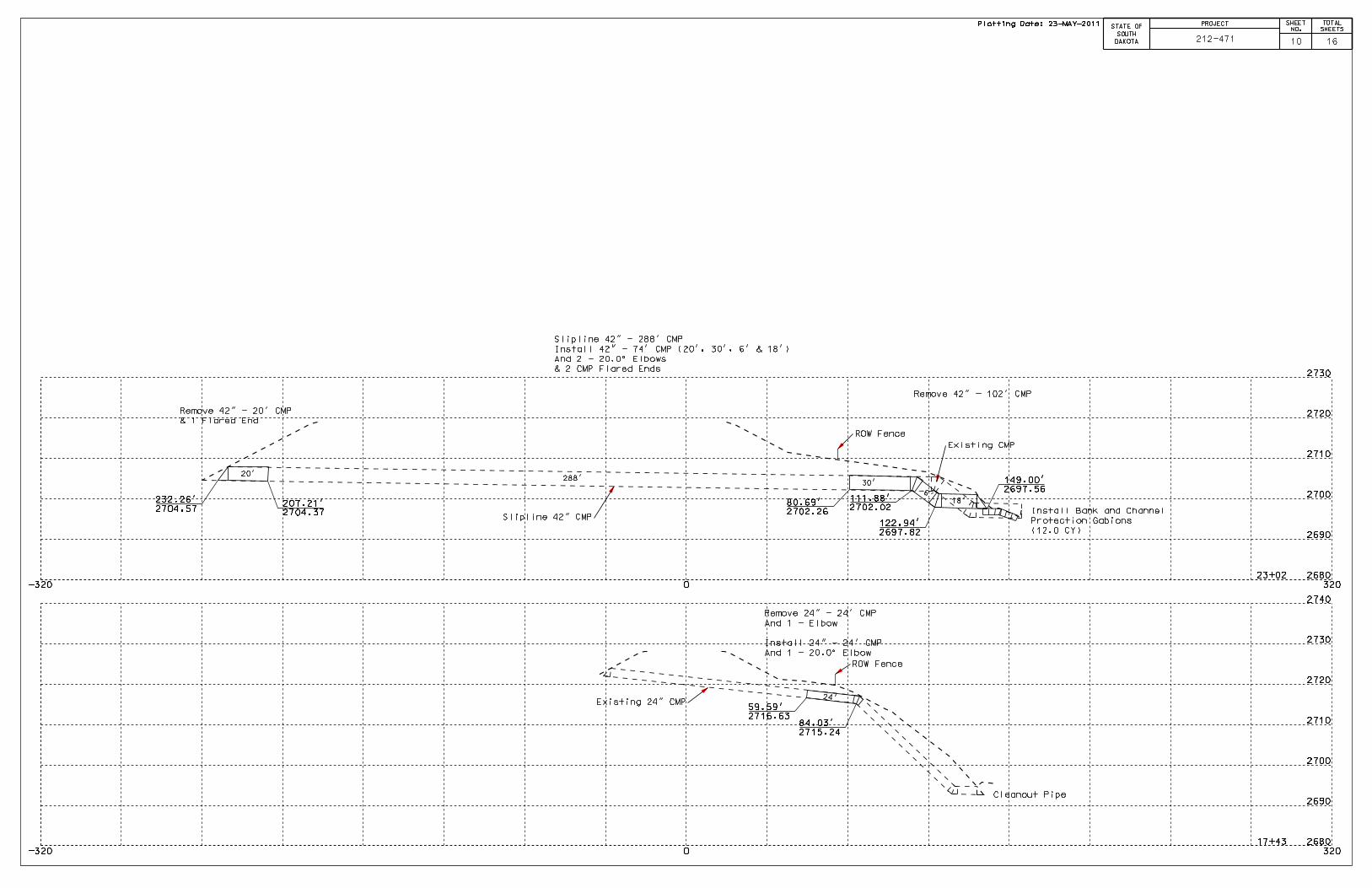
Plotting Date: 23-MAY-2011 PROJECT
STATE OF
SOUTH
DAKOTA
SHEET
NO.
TOTAL
SHEETS
10 16212-471
24’
288’
18’
6’
20’
Cleanout Pipe
ROW Fence
ROW Fence
30’
Remove 24" - 24’ CMP
And 1 - Elbow
Install 24" - 24’ CMP
And 1 - 20.0^ Elbow
122.94’
2697.82
111.88’
2702.0280.69’
2702.26
149.00’
2697.56
Install Bank and Channel
Protection Gabions
(12.0 CY)
207.21’
2704.37
232.26’
2704.57
59.59’
2716.6384.03’
2715.24
Remove 42" - 20’ CMP
& 1 Flared End
Remove 42" - 102’ CMP
Slipline 42" CMP
Existing 24" CMP
Slipline 42" - 288’ CMP
Install 42" - 74’ CMP (20’, 30’, 6’ & 18’)
And 2 - 20.0^ Elbows
& 2 CMP Flared Ends
Existing CMP

Published Date: 2nd Qtr. 2011Published Date: 2nd Qtr. 2011
S
D
D
O
T
C.M.P. FABRICATED LENGTHS FOR ELBOWS
S
D
D
O
T
C.M.P. FLARED ENDS
GENERAL NOTES:
PLATE NUMBER
Sheet 1 of 1
450. 32
June 26, 2001
All dimensions shown are nominal.
L = Linear Feet of C.M.P. required to fabricate fitting.
FABRICATED ELBOW LENGTHS FOR ALL CORRUGATIONS
Diameter Diameter Diameter
Inches Inches Inches InchesFeet Feet Feet Feet Feet
A A AL L LB C
12
15
18
21
24
30
33
36
42
48
54
60
66
72
78
84
90
96
12
15
18
21
24
30
33
36
42
48
54
60
66
72
78
84
90
96
12
15
18
21
24
30
33
36
42
48
54
60
66
72
78
84
90
96
1
1
1
2
2
2
2
2
2
2
2
2
2 2
2
2
2
2
3
3
3
3
3
3
3
3
3
3
3
3
4
4
4
4
4
4
4 4
4
4
4
4
4
4
4
4
4
4
4
4
4
5
5
5
6
6
6
6
6
6
6
6
6
6
6
6
6
6
6
6
6
6
8
8
8
8
8
8
8
8
10
10
10
10
11
12
1212
12
10
10
10
14
15
16
17
18
19
16
20
21
23
26
26
27
27
28
31
33
34
35
36
37
39
40
40
41
41
42
46
46 49
54
54
68
70
82
þÿ�2
þÿ�2
þÿ�2
þÿ�2
þÿ�1
þÿ�1
þÿ�2
þÿ�2
þÿ�3
þÿ�3
þÿ�4
þÿ�4
þÿ�3
þÿ�5
þÿ�5
þÿ�6
þÿ�6
5 to 45 Elbow 50 to 90 Elbow
2 Piece 2 Piece 3 Piece
90 Elbowo o o o o
27 2 4 27 2 4 27 þÿ�2 17 þÿ�1 4
A
AA A A A
L L
A
L
A
C B C
C
C
B
A
A
GENERAL NOTES:
PLAN
ELEVATION
TYPICAL CROSS-SECTION
STANDARD CONNECTIONS
16 6 þÿ�2� 1 Pc.
1 Pc.
1 Pc.
1 Pc.
1 Pc.
1 Pc.
þÿ�2�
þÿ�2�
þÿ�2�
þÿ�2�
16 7 6
Ga. A B H L W
Approx.
SlopeBody
46
6
6
6
8
9
8
9
10
12
16
16
14
12
12
12
12
12
16
18
18
18
18
12
12
12
12
þÿ�2�
þÿ�2�
þÿ�2�
þÿ�2
3 Pc.
3 Pc.
3 Pc.
2 Pc.
2 Pc.
2 Pc.
Alternate Type Connector
Sections may be used with
approval of the Engineer.
Galvanized
Metal
APRON
Reinforced
Edge
W AA
L
B
Dimple
Band
Collar
A
A
Ris
eH
þÿ
Sheet
1" O.D. 14 Ga. Galv. Tubing
Finish Earth Slope as Required
L
Standard Coupling Band
þÿ�A�p�p�r�o�x�.� �
Bolted on
Side Lug
Pipe
Alternate for all sizes
þÿ�T�h�r�e�a
Dia. Rod over
Top of culvert
Reinforced
Edge
A
Dimple Band Collar
bolted to end section
þÿ�w�i�t�h� &
þÿ�1
þÿ
þÿ
Half Punches
(Lugs)
Flow
Line
TUBING ATTACHMENT DETAILS
þÿ &�"� �x� ���"� �G�a�l�.� �B�
spaced 6" C. to C. Overall length
of rivets=0.78"
Flat Strap
Connector
Strap
BoltPipe
16
14
12
12
12
6
14
18
18
18
6
8
10
12
13
16
19
22
27
30
33
36
39
42
45
11
12
12
12
21
26
31
36
41
51
60
69
78
84
87
87
87
87
24
30
36
42
48
60
72
84
90
102
114
120
126
132
138
2:1
þÿ�1�
þÿ�1�
þÿ�1
3 Pc.
3 Pc.
3 Pc.
D
D
SECTION A-A
SECTION A-A (alternate)
SECTION A-A (alternate)
PLATE NUMBER
Sheet 1 of 1
450. 35
6"
(Max.)
þÿ���"� �
(Metal Edge)
NOTE:
Tubing is slipped over
the sheet and rivets or lugs
prior to forming operations
of the apron.
þÿ�R�i�v�e�t�s� �a�n�d� �B�o�l�t�s� �s�h�a�l�l� �b�e� &�"� �D�i�a�,� �M�i�n�.� �f�o�r� �1�0� �G�a�.
16 Ga. sheets. Tighten nuts with torque wrench to 25 lbs. torque.
March 31, 2000
D
(in.)
Dia. DIMENSIONS (in.)
15
18
24
12
21
30
36
42
48
54
60
66
72
78
84
"
For 30" through 84"
For 12" through 24" only
"
"
All 3 pc. bodies shall have 12 Ga. sides and 10 Ga. center panels. Width of center panels shall be
greater than 20% of the pipe periphery. Multiple panel bodies to have lap seams tightly joined
þÿ�b�y� &�"� �D�i�a�.� �g�a�l�v�a�n�i�
For 60" through 84" sizes, reinforced edges shall be supplemented with galvanized stiffener angles.
þÿ�T�h�e� �a�n�g�l�e�s� �w�i�l�l� �b�e� �2�"� �x� �2�"� �x� ��"� �f�o�r� �6�0�"� �t�h�r�o�u�g�h�
þÿ�d�i�a�m�e�t�e�r�s�.� � �T�h�e� �a�n�g�l�e�s� �s�h�a�l�l� �b�e� �a�t�t�a�c�h�e�d�
Plotting Date: 23-MAY-2011
Usernam
e - trrc11610
212-471
STATE OF SHEETTOTAL
SHEETS
PROJECT
SOUTH
DAKOTA 11 16
Published Date: 2nd Qtr. 2011Published Date: 2nd Qtr. 2011
S
D
D
O
T
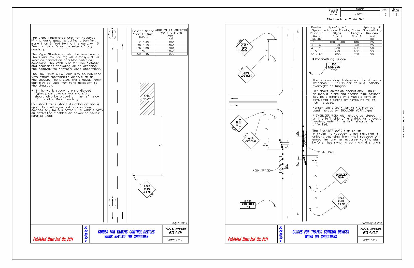
GUIDES FOR TRAFFIC CONTROL DEVICES
WORK BEYOND THE SHOULDER
S
D
D
O
T
GUIDES FOR TRAFFIC CONTROL DEVICES
WORK ON SHOULDERS
PLATE NUMBER
Sheet 1 of 1
634. 01
W20
-1
ROAD
WORK
AHEAD
The signs illustrated are not required
if the work space is behind a barrier,
more than 2 feet behind the curb, or 15
feet or more from the edge of any
roadway.
The ROAD WORK AHEAD sign may be replaced
with other appropriate signs, such as
the SHOULDER WORK sign. The SHOULDER WORK
sign may be used for work adjacent to
the shoulder.
For short term, short duration, or mobile
operations, all signs and channelizing
devices may be eliminated if a vehicle with
an activated flashing or revolving yellow
light is used.
If the work space is on a divided
highway, an advance warning sign
should also be placed on the left side
of the directional roadway.
WORK
SPACE
*
*
*
A
200
350
500
750
100060 - 75
55
45 - 50
35 - 40
0 - 30
Posted Speed
Prior to Work
(M.P.H.)
Spacing of Advance
Warning Signs
(Feet)
(A)
July 1, 2005
The signs illustrated shall be used where
there are distracting situations; such as:
vehicles parked on shoulder, vehicles
accessing the work site via the highway,
and equipment traveling on or crossing
the roadway to perform work operations.
W21
-5
SHOULDER
WORK
END
ROAD WORK
PLATE NUMBER
Sheet 1 of 1
634. 03
W20
-1
ROAD
WORK
AHEAD
AA
W21-5
SHOULDER
WORK
A
W21-5
SHOULDER
WORK
W20-1
ROAD
WORK
AHEAD
A
Posted
Speed
Prior to
Work
(M.P.H.)
Spacing of
Advance Warning
Signs
(Feet)
(A)
Taper
Length
(Feet)
(L)
Spacing of
Channelizing
Devices
(Feet)
(G)
0 - 30
35 - 40
45 - 50
55
60 - 65
350
500
750
1000
180
320
600
660
780
25
25
50
50
50
2G
WORK SPACE
WORK SPACE
END
ROAD WORK
G20-2
1 3L
1 3L
G20-2
2G
For short duration operations (1 hour
or less) all signs and channelizing devices
may be eliminated if a vehicle with an
activated flashing or revolving yellow
light is used.
Channelizing Device
Worker signs (W21-1 or W21-1a) may be
used instead of SHOULDER WORK signs.
A SHOULDER WORK sign should be placed
on the left side of a divided or one-way
roadway only if the left shoulder is
affected.
G
G
The SHOULDER WORK sign on an
intersecting roadway is not required if
drivers emerging from that roadway will
encounter another advance warning sign
before they reach a work activity area.
W21-5
SH
OU
LD
ER
WO
RK
100 - 200
February 14, 2011
The channelizing devices shall be drums or
42" cones if traffic control must remain
overnight or longer.
Plotting Date: 23-MAY-2011
Usernam
e - trrc11610
212-471
STATE OF SHEETTOTAL
SHEETS
PROJECT
SOUTH
DAKOTA 12 16

Published Date: 2nd Qtr. 2011Published Date: 2nd Qtr. 2011
S
D
D
O
T
(Typical Construction Signing)CRASHWORTHY SIGN SUPPORTS
S
D
D
O
T
BREAKAWAY SUPPORT STUB CLEARANCE
PLATE NUMBER
634. 85
Sheet 1 of 1
RURAL DISTRICT WITH
SUPPLEMENTAL PLATE
URBAN DISTRICT
RURAL DISTRICT
Paved Shoulder
Walkway7’ M
inim
um
2’
Minimum
6’ to 12’
7’ M
inim
um
7’ M
inim
um
5’ M
inim
um
4’ M
inim
um
5’ M
inim
um
6’ Minimum
6’ Minimum
1’
RURAL DISTRICT
3 DAY MAXIMUM
February 14, 2011
Level the Sign
PLATE NUMBER
Sheet 1 of 1
4"
4"
Chord Line
Top of Anchor Post or Slip Base
Ground Line
60"
ELEVATION VIEW
634.99
July 1, 2005
Anchor Post or Slip Base
PLAN VIEW
60" R
.120" Diameter
(Perimeter of stub height
clearance checks)
(Examples of stub height clearance checks)
Examples of
60" Chord Line
Clearance Checks
The top of anchor posts and slip bases SHALL NOT extend above a 60" chord line
within a 120" diameter circle around the post with ends 4" above the ground.
The 4" stub height clearance is not necessary for U-channel lap splices where
the support is designed to yield (bend) at the base.
GENERAL NOTES:
At locations where there is curb and gutter adjacent to the breakaway sign
support, the stub height shall be a maximum of 4" above the ground line at the
localized area adjacent to the breakaway support stub.
Plotting Date: 23-MAY-2011
Usernam
e - trrc11610
212-471
STATE OF SHEETTOTAL
SHEETS
PROJECT
SOUTH
DAKOTA 13 16

Published Date: 2nd Qtr. 2011Published Date: 2nd Qtr. 2011
S
D
D
O
T
BANK AND CHANNEL PROTECTION GABIONS
S
D
D
O
T
PLACEMENT UNDER PIPE END SECTIONS
BANK AND CHANNEL PROTECTION GABION
SIZE LENGTH WIDTH HEIGHT
A
B
C
D
E
F
G
H
I
6’-0"
9’-0"
12’-0"
6’-0"
9’-0"
12’-0"
6’-0"
9’-0"
12’-0"
NUMBER OF
CELLS
3’-0"
3’-0"
3’-0"
1’-6"
1’-6"
1’-6"
1’-0"
1’-0"
1’-0"
3’-0"
3’-0"
3’-0"
3’-0"
3’-0"
3’-0"
3’-0"
3’-0"
3’-0"
2
2
2
3
3
4
4
4
3
2.0
3.0
4.0
1.0
1.5
2.0
0.7
1.0
1.3
Above Dimensions subject to mill tolerances.
STANDARD SIZES
GABION DETAILS
3’-0"L
ength B
Length
C 3’-0"L
ength D
Len
gth
E
Len
gth
F
3’-0"L
ength G
Length
H
Len
gth
I
PLATE NUMBER
720.01
Sheet 1 of 1
CAPACITY,
Cu. Yd.
GENERAL NOTES:
All fasteners shall be placed where the mesh weaves around the selvage wire at the vertical and
horizontal joints.
Lacing and internal connecting wire shall be 0.0866 inch diameter steel wire ASTM A641 Class 3
soft temper measured after galvanizing and for PVC coated gabions shall be 0.0866 inch
diameter steel wire measured after galvanizing but before PVC coating.
Interlocking fasteners for PVC coated gabions shall be high tensile 0.120 inch diameter
stainless steel wire conforming to ASTM A313, Type 302, Class 1. The spacing of the interlocking
fasteners during all phases of assembly and construction shall not exceed 6 inches.
The lacing procedure is as follows:
þÿ�1�.� � � � � � � �C�u�t� �a� �l�e�n�g�t�h� �o�f� �l�a�c�i�n�g� �w�i�r�e� �a�p�p�r�o�x�i�m�a�
exceeding 5 feet.
2. Secure the wire terminal at the corner by looping and twisting.
3. Proceed lacing with alternating single and double loops at a spacing not to exceed 6 inches.
4. Securely fasten the other lacing wire terminal.
Wire lacing or interlocking type fasteners shall be used for gabion assembly and final
construction of gabion structures. Interlocking fasteners for galvanized gabions shall
be high tensile 0.120 inch diameter galvanized steel wire measured after galvanizing. The
galvanizing shall conform to ASTM A641-92 Class 3 coating. Fasteners shall also be in accordance
with ASTM A764, Class II, Type III.
Length
A
June 26, 2001
3’-0"
1’-6
"
1’-0
"
66" RCP & CMP
4.5 Cu. Yds.
6.0 Cu. Yds.
15.5 Cu. Yds.
17.0 Cu. Yds.
21.5 Cu. Yds.
26.0 Cu. Yds.GENERAL NOTES:
78" RCP & CMP
27.0 Cu. Yds.
84" RCP & CMP
72" RCP & CMP
60" RCP & CMP
48" & 54" RCP & CMP
30" & 36" RCP & CMP42" RCP & CMP
720.03
PLATE NUMBER
Sheet 1 of 1
12", 18", & 24" RCP & CMP
12", 18", & 24" RCP Arch & CMP Arch 30" & 36" RCP Arch & CMP Arch
10.0 Cu. Yds.
42" RCP Arch & CMP Arch
48" & 54" RCP Arch & CMP Arch
60" RCP Arch & CMP Arch
12.0 Cu. Yds.
72" RCP Arch & CMP Arch
June 26, 2001
Gabions at outlets of C. M. pipe and R. C. pipe shall be placed under the end section a
distance of 2’ from the outlet end of the section. For C. M. pipe end section installations,
the upper fabric of the gabions shall be modified to accommodate the metal end section
in a manner approved by the Engineer.
Quantities shown on this standard plate are based on standard gabion sizes D, E, and F (See
Standard Plate 720.01).
Plotting Date: 23-MAY-2011
Usernam
e - trrc11610
212-471
STATE OF SHEETTOTAL
SHEETS
PROJECT
SOUTH
DAKOTA 14 16

Published Date: 2nd Qtr. 2011Published Date: 2nd Qtr. 2011
S
D
D
O
T
HIGH FLOW SILT FENCE
S
D
D
O
T
HIGH FLOW SILT FENCE
1 EXCAVATE TRENCH
Flow
PLATE NUMBER
Sheet 1 of 2
4"
4"
Flow
Fabric for silt
fence shall be
36" minimum width.
Silt Fence Fabric
734. 05
December 23, 2003
MANUAL HIGH FLOW SILT FENCE INSTALLATION
1’-6
"
5’
4"
4"
6’
2 DRIVE STEEL T FENCE POSTS
3’-6"
The elevation at these locations shall be, at
a minimum, higher than the top of the silt
fence fabric at its lowest elevation.
Post spacing shall be 3’ for these
types of applications of silt fence.
All other components of the silt
fence shall be the same as shown
above.
The silt fence length and width may be
adjusted due to a larger pipe, multiple pipe,
or other circumstances during construction
as determined by the Engineer.
Flow
Wheel
Compact
Soil
Steel T
Fence Posts
3 ATTACH SILT FENCE FABRIC
A
A
SECTION A-A
8" staples shall
be placed at
each post to
secure the silt
fence fabric to
the bottom of
the trench.
Steel T Fence Post
Attach the silt fence fabric with a
total of 4 plastic or wire ties per
post. Three ties shall be used at
the top and 1 tie shall be approximately
at mid-point of the post.
4 BACKFILL TRENCH AND WHEEL COMPACT SOIL
Plastic or
Wire Ties
PLATE NUMBER
Sheet 2 of 2
Operation
Fabric above
ground
Horizontal Chisel point
(3" width)
8" t
o 1
2"
Roll of silt
fence fabric
Slicing blade
þÿ�(���"� �
Sliced In
Fab
ric D
ep
th
734. 05
MACHINE SLICED HIGH FLOW SILT FENCE INSTALLATION
December 23, 2003
6’
DRIVE STEEL T FENCE POSTS
FlowFlow
1’-6
"3’-6"
Silt Fence Fabric
2 WHEEL COMPACT SOIL ABOVE SLICED IN
PORTION OF FABRIC AND THEN DRIVE
STEEL T FENCE POSTS.
WHEEL COMPACT SOIL
BY MACHINE SLICING METHOD.
1 INSTALL SILT FENCE FABRIC
SECTION A-A
Plastic or
Wire Ties
Steel T
Fence Post
Flow
Fabric for silt
fence shall be
36" minimum width.
3 ATTACH SILT FENCE FABRIC
A
A
Attach the silt fence fabric with a
total of 4 plastic or wire ties per
post. Three ties shall be used at
the top and 1 tie shall be approximately
at mid-point of the post.
Silt Fence
Fabric
Wheel
Compacted
Areas
Wheel
Compacted
Areas Flow
Flow
The silt fence length and width may be
adjusted due to a larger pipe, multiple pipe,
or other circumstances during construction
as determined by the Engineer.
The radius of the silt fence shall be the
minimum capable by the slicing machine.
The post spacing shall be 3’ for these
types of applications of silt fence. All the
other components of the silt fence shall
be the same as shown above.
The elevation at these locations shall be, at a minimum, higher than
the top of the silt fence fabric at its lowest elevation.
GENERAL NOTE:
If a trench can not be dug or the silt fence fabric can not be sliced in due to the type
of earthen material (such as rock), then a row of 30 to 40 pound sandbags butted
end to end shall be provided on top of the extra length of silt fence fabric to prevent
underflow.
Plotting Date: 23-MAY-2011
Usernam
e - trrc11610
212-471
STATE OF SHEETTOTAL
SHEETS
PROJECT
SOUTH
DAKOTA 15 16

Published Date: 2nd Qtr. 2011Published Date: 2nd Qtr. 2011
S
D
D
O
T
EROSION CONTROL WATTLE
S
D
D
O
T
EROSION CONTROL WATTLE
PLATE NUMBER
2" t
o 3
"
See Detail B
1:1
2:1
3:1
4:1
10
20
30
40
75
50
2%
3%
4%
5%
150
100
734.06
Excavated Material
from Trench
SlopeSpacing
(Ft)
CUT OR FILL SLOPE
INSTALLATION
Grade
DITCH INSTALLATION
Spacing
(Ft)
CUT OR FILL SLOPE INSTALLATION
Spacing Varies (See Table)
3" t
o 5
" T
rench
Flow
9"
Min
.
6"
6"
Ends of Erosion
Control Wattles
SECTION A-A
DETAIL B DETAIL C
Flow
ELEVATION VIEW
Point B
Point APoint A
DITCH INSTALLATION
PLAN VIEW
Flo
wPoint A
Point B
Point A
A
A
Flow
Point A
Point B
Point A
DITCH INSTALLATION
ISOMETRIC VIEW
Wood Stake
Wood Stake
Wood Stake
(Typ.)
Wood Stake
Sheet 1 of 2
(TYPICAL OF ALL INSTALLATIONS)
December 23, 2004
PLATE NUMBER
GENERAL NOTES:
734.06
Where installing running lengths of wattles, the Contractor shall butt the second
wattle tightly against the first and shall not overlap the ends. See Detail C.
The Contractor shall dig a 3" to 5" trench, install the wattle tightly in the trench so
that daylight can not be seen under the wattle, and then compact the soil excavated
from the trench against the wattle on the uphill side. See Detail B.
At cut or fill slope installations, wattles shall be installed along the contour and
perpendicular to the water flow.
Sheet 2 of 2
The stakes shall be 1"x2" or 2"x2" wood stakes, however, other types of stakes such as
rebar may be used only if approved by the Engineer. The stakes shall be placed
6" from the ends of the wattles and the spacing of the stakes along the wattles
shall be 3’ to 4’.
The Contractor and Engineer shall inspect the erosion control wattles once every
þÿ�w�e�e�k� �a�n�d� �w�i�t�h�i�n� �2�4� �h�o�u�r�s� �a�f�t�e�r� �e�v�e�r�y
Contractor shall remove, dispose, or reshape the accumulated sediment when
necessary as determined by the Engineer.
All costs for removing the erosion control wattle from the project including labor,
equipment, and materials shall be incidental to the contract unit price per foot for
"Remove Erosion Control Wattle".
All costs for furnishing and installing the erosion control wattles including labor,
equipment, and materials shall be incidental to the contract unit price per foot
for the corresponding erosion control wattle bid item.
At ditch installations, point A must be higher than point B to ensure that water
flows over the wattle and not around the ends.
Sediment removal, disposal, or necessary shaping shall be as directed by the Engineer.
All costs for removing accumulated sediment, disposal of sediment, and necessary
shaping shall be incidental to the contract unit price per cubic yard for "Remove
Sediment".
December 23, 2004
Plotting Date: 23-MAY-2011
Usernam
e - trrc11610
212-471
STATE OF SHEETTOTAL
SHEETS
PROJECT
SOUTH
DAKOTA 16 16