benchcrafted tail vise - classic hand tools · pdf filethe benchcrafted tail vise is...
TRANSCRIPT
1
Contents:
Quantity Description
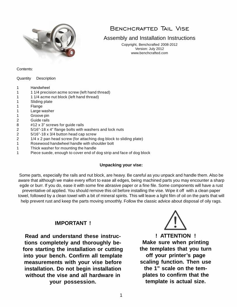
1 Handwheel1 1 1/4 precision acme screw (left hand thread)1 1 1/4 acme nut block (left hand thread)1 Sliding plate1 Flange1 Large washer1 Groove pin2 Guide rails8 #12 x 3” screws for guide rails2 5/16”-18 x 4” flange bolts with washers and lock nuts2 5/16”-18 x 3/4 button head cap screw2 1/4 x 2 pan head screw (for attaching dog block to sliding plate)1 Rosewood handwheel handle with shoulder bolt1 Thick washer for mounting the handle1 Piece suede, enough to cover end of dog strip and face of dog block
Unpacking your vise:
Some parts, especially the rails and nut block, are heavy. Be careful as you unpack and handle them. Also beaware that although we make every effort to ease all edges, being machined parts you may encounter a sharpegde or burr. If you do, ease it with some fine abrasive paper or a fine file. Some components will have a rust
preventative oil applied. You should remove this oil before installing the vise. Wipe it off with a clean papertowel, followed by a clean towel with a bit of mineral spirits. This will leave a light film of oil on the parts that will
help prevent rust and keep the parts moving smoothly. Follow the classic advice about disposal of oily rags.
Benchcrafted Tail ViseAssembly and Installation Instructions
Copyright, Benchcrafted 2008-2012Version: July 2012
www.benchcrafted.com
! ATTENTION !Make sure when printing
the templates that you turnoff your printer’s page
scaling function. Then usethe 1” scale on the tem-
plates to confirm that thetemplate is actual size.
IMPORTANT !
Read and understand these instruc-tions completely and thoroughly be-
fore starting the installation or cuttinginto your bench. Confirm all templatemeasurements with your vise beforeinstallation. Do not begin installationwithout the vise and all hardware in
your possession.

2
Assembling the Sliding Plate and Nut
The Benchcrafted Tail Vise is universal. You can assemble the sliding plate to the nut block for eitherright-handed or left-handed use. If you are unsure of which one to choose, read the FAQ section on TailVises at our website. Unless you have a special situation, you’ll most likely assemble the plate to the nutbased on your dominant hand. If you’re right-handed, assemble the vise in right-hand configuration, etc.
Tools required:
3/16” Allen wrench
The plate attaches to the nut block with two included 5/16”x 3/4 button-head cap screws. Follow thepictures below to assembled your plate and nut according to right-hand or left-hand use. Visit our videogallery page for a video on assembling the vise and sliding plate assembly.
End-cap view (as if you were standing at the Tail Vise end of the bench andlooking down) :
Left-hand Right-hand
Left-hand Right-hand
Opposite end view (as if you were standing at the far opposite end of thebench and looking down towards the Tail Vise end)

3
Assembling the Handwheel and Screw
The Benchcrafted Tail Vise and Glide Leg Vise ship unassembled. You will need to install three partsonto the 18” acme screw’s shaft: the washer, flange, and handwheel. It only takes about a minute.
Tools required:
Small hammerPin punch or large nail set
1. Remove the handwheel, flange, large washer, 18” acme screw, groove pin and logo from the box and remove the VCIpaper.
2. First, place a couple drops of light machine oil on the shaft end of the acme screw near the shoulder for lubrication, thenslide the washer onto the shaft.
3. Next, slide the flange onto the shaft.
IMPORTANT : Face the side with the two countersunk holes away from the screw. The countersinks need to face OUT oncethe vise is mounted in the bench..
4. Slide the handwheel onto the shaft, lining up the cross hole in the handwheel’s hub with the cross hole in the shaft. Peerdown into the hole and position the handwheel until the two holes line up precisely.
5. Get the groove pin, punch and hammer. Examine the groove pin. One end is smoothly round, with virtually no grooves.The grooves get wider as they reach the opposite end of the pin. See fig.1
6. Insert the SMOOTH END WITH NO GROOVES first into the cross hole in the hub and with finger pressure insert the pinuntil you feel it engage the hole in the shaft. If you can’t insert it far enough with finger pressure, use the hammer to lightlytap the pin to get it moving towards the shaft. Try to keep the hub in line with the cross hole in the shaft as you tap the pinin. Keep tapping the pin in until you feel a little resistance as the pin meets the hole in the shaft. Tap some more until youfeel the pin engage the hole in the shaft. Now take the pin punch and place it on the head of the pin and finish driving thepin through the shaft and the opposite side of the hub. Use light taps. The fit is machined precisely, it doesn’t take muchforce. Do not over drive the pin, stop when its centered in the hub’s diameter. The flange should spin freely on the shaft andhave a little bit of play in the fit.
Getting Started
The vise can be readily adapted to thicker or thinner benches. Instructions will assume you are installingthis vise in the construction of a new bench with a 4” thick top. The vise installation is not complex, andonce you understand how it works, adapting it to fit other bench styles or existing benches will be straight-forward. Templates at the end of these instructions show how to adapt the vise for thinner benches. If youare installing in a left-handed position, we provide step photos of left-handed installation within theseinstructions . Unless noted, pics and illustrations are for right-hand installation.
NOTE: The templates are sized for a 4” thick top. It’s important to register the templates from the topsurface of the bench if your bench is not 4” thick. This ensures the handwheel’s rim will remain below thetop plane of the bench.
smooth end
fig. 1

4
The first step in installing the vise is to prepare the top of the bench. If you’re building from scratch you’llhave four components. The top, dog hole strip (made up of two pieces if you’re using square dogs) frontlaminate and end cap. If you’re retrofitting you’ll need to add an end cap at the very least. You may alsowant to add a dog hole strip and front laminate to make the install more precise. Otherwise you’ll have tocreate the cavity and slot instead of building them up from the four components. The vise connects to thebench in three places: the two guide rails are screwed into the underside of the bench, and the screw/handwheel assembly bolts to the end cap. The more precisely you attach these parts, the better the visewill work. Work carefully and attentively and you’ll be rewarded with a sweetly working vise.
Note: For clarity, a narrow bench top is used for the illustrations. This is actually the front section from ourSplit Top Roubo.
Mill all your stock to final dimension, but leave the end cap and front laminate long. You’ll join them at thecorner as you install the vise.
With a 3" wide end cap, the length of the cavity from the inside of the end cap shouldn’t be less than 13-7/8". For maximum vise capacity, the slot portion of the cavity can be up to 17-3/4" long. This will allow themost travel of the sliding plate assembly. Before using these dimensions however, lay out the cavity andslot on your actual bench to double check the dimensions and to see how they work with your individualbench and leg locations. If your end cap is narrower than 3", take this into consideration when planningthe length of your slot.

5
Here you can see the layout lines for the cavity, withthe dog hole strip and long front laminate clamped inplace. Slip a scrap of wood the same width as thedog hole strip in the slot between front laminate anddog hole strip to keep the front laminate rigid duringrouting. Pictured is one pass of the cavity excavationwith the router.
If you like, you can stop the cavity for the nut blockshort of the slot’s end. This keeps more of yourbenchtop intact. Position the screw assembly toaccomodate your end cap (here, 2-7/8”) and threadon the nut fully.
Now mark the position of the nut on the undersideof the top and add about 1/4” past the nut. The nutwill never travel past this location. (current slidingplates now feature a rectangular dog hole)
To begin the cavity excavation lay out the dimen-sions of the cavity that the nut block rides in directlyon the end of the top. You should have already cutthe tenon for the end cap, if you are using a tenon.The cavity dimensions are found in the illustrationabove, and on the templates. We use a router toremove the material. Clamp the dog hole strip andfront laminate in place to provide support for therouter base and fence. See the Benchcrafted FAQfor a video showing some technique for routing thecavity.

6
The excavated cavity. The remainder of the cavitythat was left may interfere with the sliding platedepending on how deeply you mortise the guiderails. You may have to recess this area sllightly toallow the plate to travel freely.
The completed cavity with dog strip and front lami-nate in place.
The cavity with (long) end cap and doghole strip in place.

7
Two views of a left-handed installation.
Below: front laminate removed for clarity. End cap in place.

8
With the cavity excavated you can glue the dog hole strip on. After that, finish your end cap-to-top joinery(but don’t install it permanently yet.) We like to use a tenon reinforced with two bolts and our End CapBarrel Nuts. These are easy and quick to install. You can also use simple hex or square nuts in blindholes that intersect with the bolt holes. Another option is to use 1/2” Spax brand lag screws to attach theend cap. It’s not as strong, but we’ve found it to be plenty robust. A spline helps position the end cap onthe end of the top for drilling, if you don’t want to use an integral tenon. Use the sequence on page 10 todrill the end cap for lag screws. With the end cap joinery complete, you know exactly where the end capwill be in the final assembly. Now place the template on the outside of the end cap (registered from thetop of the bench) and line it up horizontally with the slot where the dog block rides. Mark with an awlthrough the template, then drill the counterbore for the washer (behind the flange) at 1-3/4” dia, 3/16”deep, the clearance hole for the main screw at 1-3/8" to 1-1/2” dia., and the two holes for the flangeattachment at 5/16" dia.

9
With the end cap-to-top joinery complete you can join the front laminate to the end cap. With the end capinstalled (but not permanently) Slide the front laminate to the inside of the end cap and make sure the slot(where the dog block rides) is parallel and consistent in width along its entire length.
Mark the end cap length directly from the front face of the front laminate and cut it to length. In the picturebelow you can see that the dovetails have already been cut on the end of the front laminate for joining tothe end cap. This is why you kept the front laminate long, to leave room for cutting joinery at the tail viseend.

10
This large dovetail is beautiful in the finished bench, but its not a requirement. However, if you’d like to tryit, we wrote a detailed article “How To Make Condor Tails” for Popular Woodworking Magazine issue#191. The issue and accompanying article are available at www.shopwoodworking.com
An easier method is to use massive lag screws to fasten the end cap to the front laminate. First drill thepilot holes in the end cap on a drill press using a bit that matches the root diameter of your lag screw.Fasten the end cap in place on the bench top and then clamp the front laminate firmly and accurately inplace. Now grab a manual drill and use the holes in the end cap to guide your bit straight into the end ofthe front laminate. Remove the end cap and enlarge the holes in the end cap (to the size of the threads)and bore deeper into the front laminate if necessary for the lag screws. Be careful and diligent here,since these holes need to be positioned precisely. Use a sharp bit and back the drill out frequently toclear the chips. Reassemble the end cap and drive the lags into the front laminate to cut the threads.When you glue the front laminate to the dog hole strip, have your socket wrench handy so you can reinstallthe lags immediately during the glue-up.
Make sure you use 1/2” Spax brand lags. They are made in American or Germany, and are the only lagscrews we recommend for this technique, since they are properly heat treated, and have deep, robustand crisp threads. Do not use the hardware-store variety lags that are made in Asia. They are soft, haveblunt, shallow threads and aren’t much better than using a smooth dowel. Our local big box store carriesSpax, but you can get them online from places like McFeely’s and Ultimate Garage.

11
If you’re cutting the dovetail, you can now transfer the tail locations to the end of the end cap. Clamp thefront laminate in place, raising it up with a couple blocks the same thickness as the tails (cut a shallowrabbet in the backs of the tails to help in locating the tails square and tight to the inside of the end cap.)Above you can see the bolts and captive nuts holding the end cap on.
Marking the pin locationsfrom the tails.
The joint going together.
When you’re satisfied with the fit of the end cap and front laminate you can assembly them permanently.

12
With the bench’s top completely assembled, the next step is to excavate the mortises for the two guiderails. The mortises are laid out on the underside of the top. Use the template, again registered from thetop of the bench to determine the depth of the mortises. The inner edges of the rails should end up flushwith the inside face of the front laminate and the inside edge of the cavity. If your bench is exactly 4” thick,you can simply mortise 1/4” deep. If you mortise too deep its not a huge mistake. You can simply cutsome shims for the mortises to locate the rails properly. The distance from the rails to the tapped hole inthe nut block is critical. We’ve designed the vise for a bit of wiggle room here, but best to shoot for spoton. Again, if things are off, its easily corrected with shims. You can use paper, veneer, or even layers ofthe ever-handy blue painter’s tape. Just make sure the rails seat flatly and in the same plane. They needto be coplanar for the sliding plate to ride smoothly.

13
The sliding plate rides in grooves milled into the guide rails. Although the edges of the sliding plate andtheir mating grooves are accurately machined, it’s possible to position the guide rails too close together.This could cause the sliding plate to bind in the grooves. You want a loose fit here. It’s best to positionthe guide rails so the sliding plate has some lateral movement. 1/16”-3/32” of side-to-side play is ad-equate. The templates account for this, but best to double check in real time. Place the rails directly onthe surface and position them so the inside edges are flush with the inside of the front laminate andcavity. Now gently shift the plate back and forth between rails to check for this play. Make sure the railsdon’t move. You can clamp them in position for this test if you wish.
In use, the lateral tracking of the plate is not dependant on the amount of play between the guides. The fitof your dog block (which you fit as the last step), along with the screws’s alignment will determine theultimate travel of the vise, so it’s important to install the guides with this side-to-side play. This also allowsfor some wood movement during changes in your shop environment.
It’s also important that the mortises for the guide rails be parallel to each other to prevent the sliding platefrom binding, parallel to the slot (to match the travel path of the dog block), and square in both planes tothe end cap, so when the screw is engaged, the plate travels smoothly along the screw. There is someroom for error, but it’s best to shoot for perfection. This will guarantee a smooth running vise. The mostimportant plane to consider is whether the guides are vertically parallel (coplanar). The grooves in theguide rails are milled for a smooth fit with the sliding plate, so there isn’t much room for error here. Again,shims can correct almost any error.

14
Once you’re satisfied with the location of the rails, scribe around them with a knife or sharp pencil. Makesure you position the rails along their length so the end screw hole falls within the end cap. This reallyadds a lot of strength to the entire top, further locking the end cap to the top. Also be sure the oppositeend of the rails are not going to interfere with any joinery for attaching the top to the base, or the leg itself.The guide rails are 18” long.
Cutting the mortises is easy work with a router, 3/4” straight bit and edge guide. Square up the ends witha chisel. If you work by hand, chisel and router plane are the tools for the job. Either way, make the floorsof the mortises as dead flat as you can, so when you drive the screws through the rails, they seat com-pletely flat. If one end of your mortise is sloping down, the screws will deform the rail. Try to make the railsfit precisely with no play. This will help keep the rails from shifting when you drill the pilot holes for theattachment screws. Once the mortises are cut, slip the rails and sliding plate assembly in place and testthe sliding plate again for smooth movement and some play. Also make sure the nut block isn’t touchingwood in the cavity. If it is, correct this now. The sliding plate should never come in contact with the top.

15
With the rails and sliding plate in place, thread in the screw assembly, fasten the flange to the end cap(use plain 5/16 nuts, as the nylon lock nuts should be used only for the final assembly) and test the opera-tion of the vise. Everything should run smoothly and freely. Sight down alonside the screw, it should beparallel with the slot. If you’re satisfied with the fit you can drill for the eight #12 screws that hold the railsto the top. Use a properly sized center punch (a bradpoint bit will also work) to locate the holes, directlythrough the rails. You may need to remove the rails to pre-drill deep enough for the 3” screws. Drill anddrive the four corner screws first. Tighten one, then test the function of the vise. Repeat for the remainingthree screws. If the vise binds after tightening a screw, you’ve located the spot where you many need toshim a rail. Drill and drive the remaining screws the same way.
Extra long flange bolts are provided to accommodate a range of end cap thicknesses, so you may wantto cut off the extra thread past the nut. Don’t cut them too short. These two bolts provide the opposingforce for the vise and must be fully engaged in the lock nuts.
A couple drops of light machine oil between the flange and the handwheel’s hub (apply while turning thehandwheel) helps keep the screw turning smoothly.

16
Next, make the dog block. It should fit well in the top’s slot, but not tight. It needs to slide freely. Make theblock a little too tall, then plane it flush to the top.
For square dog holes, the dog block is made just like the dog strip on a bench top. (The dog hole ismilled into the side of the block, then the outer cheek is glued on.)
Install the dog block by marking from below with a center punch (or simply drilling directly through theattachment holes) and predrilling for the two 1/4 x 2 pan head screws from below. The holes in the plateare sized for a tight fit , you may need a screwdriver to drive the screws through the plate. It shouldn’t takemuch.These screws are used to hold the block in place only. Clamping force is transferred directly to theblock and dog by the vertical portion of the massive steel nut block. Make sure you drill accurately. Youdon’t want the screws to be offset, thus forcing the dog block tight against the inside of the slot causingfriction. Ideally, the sides of the dog block fit loosely in the slot for smooth and effortless action. If you findone side rubbing the slot, remove the dog block and plane that side until it rides smoothly.
The face of the dog block and the end of the dog hole strip are lined with suede (included) for a good gripwhen holding work with the jaw of the vise.

17
The handwheel is cast iron and may rust. Check our FAQ for info on treating the handwheels to helpprevent this. If your shop is conditioned this shouldn’t be a problem. The rest of the vise is lightly oiledsteel and should be kept lubricated for smooth action. Like any fine tool, the vise should be periodicallycleaned. It’s important to keep the screw and nut free of built-up dust and grime. The precision acmescrew is smooth and polished, so it should need only occasional attention. Unbolt the flange and back thescrew out of the bench. Clean out the threads with compressed air or a small brush. Also clean the dustand grime from the guide rail slots. Reapply a light lubricant periodically, depending on your shop condi-tions.
Using the vise is simple. When clamping between dogs it’s easy to overdo it. Just spin the handwheel,advancing the dog block up to your workpiece and the let the dog stop against it. It’s usually not neces-sary to tighten the vise past this point, especially with thinner pieces. We recommend lining the faces ofyour dogs with leather, this will dramatically increase the grip of the vise while using less clamping pres-sure. We offer suede scraps on our ordering page for such a purpose. You’ll be impressed with theholding power of the vise. It’s not necessary to crank the handwheel tightly to hold the workpiece. Whenclamping between jaws (as in dovetailing or other vertical sawing operations) spin the vise to theworkpiece, then grasp the rim of the handwheel and give it another half inch or so turn. If you’ve lined yourjaws with suede, this provides enough grip that you can even move your bench with the workpiece--muchmore force than any joint cutting operation would entail.
For more tips and techniques, please visit our blog which contains lots of information on using the vise.
http://benchcrafted.blogspot.com/ Select “Tail Vise” from the “Categories” list at the right of the blog.
If you have any questions about the installation, we’re glad to help. Contact us at [email protected].
Thank you for purchasing the Benchcrafted Tail Vise. We hope you enjoy using the vise as much as wedo.

Frontlaminate1-1/2” x 4”
Benchtop
Benchcrafted Tail ViseTemplate v.21-1/4”
Bottom of 4” benchtopto center of screw
Dog block1-3/4” wide
1-15/16
2-3/4”benchtop to center of screw
2-5/165/16 dia.thru
5/16 dia.thru
STOP! Check templatefor actual size
1” 1”
!

Frontlaminate1-1/2” x 4”
Benchtop
1-1/4”Bottom of 4” benchtopto center of screw
Dog block1-3/4” wide
1-7/8
2-3/4”benchtop to center of screw
2-5/16
1-15/16
5/16 dia.thru
5/16 dia.thru
Benchcrafted Tail ViseTemplate v.2Left-hand installation STOP! Check template
for actual size
1” 1”
!

Frontlaminate1-1/2” x 3”
Benchtop
1-1/4”Bottom of 4” end capto center of screw
Dog block1-3/4” wide
1-15/16
2-3/4”benchtop to center of screw
2-5/16
3/4” shim
3/4” shim
5/16 dia.thru
5/16 dia.thru
Benchcrafted Tail Vise3” Top Template v.2
STOP! Check templatefor actual size
1” 1”
!