behaviour of circular sandwich panel under static … · behaviour of circular sandwich panel under...
TRANSCRIPT

Jurnal Mekanikal December 2005, No. 20, 78 - 95
78
BEHAVIOUR OF CIRCULAR SANDWICH
PANEL UNDER STATIC LOADING
Amran Alias Mohd Ruzaimi Mat Rejab Mohd Radzai Mohamad
Hazizan Md Akil Nor Azlan Ahmad Nor
Composite Centre (PUSKOM)
Faculty of Mechanical Engineering Universiti Teknologi Malaysia E-mail: [email protected]
ABSTRACT
In this paper, the performance and behaviour of the circular sandwich panel under static loading was examined. The circular sandwich panel was centrally loaded by using hemispherical and flat indenters on their respective support units. The panel materials used specifically for this project are mild steel skin and PVC foam namely R55 and polyurethane (PU) foam cores. The aim of this study is to obtain experimental evidence of the failure modes of the circular sandwich panels under concentrated load at the centre of panels, simply supported around the edge corners for the panel. After static tests, the whole curves for each panel were determined. The relation between the observed damage development, the property of degradation during the static test of the panels was investigated. Keywords: Circular sandwich panel, PU foam, PVC foam (R55), failure modes. 1.0 INTRODUCTION A sandwich panel can be characterized as a composite that constitutes of two faces separated by and linked to a core that is less stiff and less dense. The faces and the core are usually connected by adhesive that provides structural continuity across the depth panel. The important role of the faces of a sandwich panel is to bear tensile, compressive, flexural and shear stress resultants that act parallel to the plane of the panel. Faces may also act to distribute localized loads and reactions to the softer and weaker core. The core of a sandwich panel separates the faces and holds them in steady position. It gives the shear load path between the faces and together with skin, it carries loads or reaction that are applied normal to the plane of the panel. An ample range of skin and core materials are available in large number of combinations. It can be a beam, a panel or any other special shape. The skin can be of metal, wood, plastic, FRP composites or any other structural

Jurnal Mekanikal, December 2005
79
material. Likewise, cores may be made of honeycomb, corrugated or foamed cellular materials. Considerably good structural integrity with less weight. It has been very useful in offshore panel structure and in aircraft industry where minimizing weight is important. The development of study on sandwich plates was initiated by the study of monolithic plates. The collapse loads of rigid-plastic plates are determined by limit analysis [1]. The early works on the general theory of limit analysis were developed [1] as a major component of the theoretical approach of perfectly plastic solid in many fields. Later, comprehensive study on the relationship of load and displacement of plates, namely square and circular, with different boundary condition were given in few references [2-4]. The perfect-plastic theory derives its simplicity from two assumptions; that the material is perfectly plastic i.e. no strain hardening and that there is no significant changes is geometry which would affect the equilibrium equation of structure. According to this theory, the plastic collapse of structure takes place at constant load i.e. no deformation takes place until a ‘limit’ is reached which followed by continuous deformation. In general, it requires a plastic deformation mechanism to be formed. When the limit is reached, bending deformation is concentrated at yield hinges. The deformation of the structure becomes possible only when yield hinges have developed number to transform the structure into mechanism. When the ratio of plate thickness to plate radius is relatively small, in order for the plastic deformation to continue, once initiated, presumably some increase in applied load would be required. These effects are due to membrane action. At the initial stages of deformation of the plates, bending action always predominates over membrane action. Consequently, close to collapse or deformation is about to occur, the associated stretching at the middle cannot take place due to the absent of deformation. The main purpose of limit analysis is finding the flow limit under given types of loading. The load intensity at the flow limit is called the load carrying capacity of structure. The load carrying capacity of perfectly plastic circular plates has been discussed by Hopkins and Prager [5]. In the analysis, a limiting condition for the strength of the material has to be assumed in order to obtain a collapse load; the most commonly criteria used are Tresca and Von Mises. The application of these criteria to yielding of plates is discussed by Hopkins [6]. The problems of plate with simply supported or built in at edge and subjected to simple symmetric loading are discussed using the Tresca yield condition [5]. Later, Onat and Haythhornthwaite [7] examined that post yield behaviour of circular plates is conditioned by change of geometry and by strain hardening. The simple plastic theory which involve; negligible geometry changes and no strain hardening are not justified by experiments for many kinds of structures, e.g. plates. They studied those effects on a simply supported circular plate under central point loading which begins to deform into a shallow cone. They analyzed the plastic limit load of shallow conical shells using an upper bound technique and deduced a load-deflection curve for large deflection of an initially flat plate. Their study indicated that the increase in load intensity above the value predicted by the simple plastic theory is proportional to the square of the transverse deflection. The agreement between theory and experiment was quite good only for thicker plate

Jurnal Mekanikal, December 2005
80
(diameter/thickness, d/t < 20). For very thin plates, large deflection in the elastic range was observed. Young [8] also established that large deflection in elastic range was an important behaviour of plates with small thickness to diameter ratio. Calladine [9] proposed a new promising approach to simplify the analysis of large deflection of plates in plastic range. The idea is basically to trace approximately the deflection history of a plate by means of succession of upper bound calculation, made by considering the structure to be three-dimensional body of perfectly plastic material. His theoretical approach has been particularly chosen for the present study as the theoretical approach for comparison of the experimental works. Allen [10] presented a comprehensive discussion on the general sandwich construction. He also discussed sandwich panels subjected to uniformly distributed load over the whole area of the top skin. The analysis of simply supported sandwich panel with centrally point loading is deduced from above as a local distributed over a circle (indenter size) at the centre of the top skin. The literature about wrinkling problem is less than that bending problem. Gough, Elam and De Bruyne [11] were the first to analyze the problem in the strut stability which is applicable to anti-symmetrical wrinkling of sandwich struts. Hoff and Mautner [12] made the same kind of analysis for symmetrical wrinkling of sandwich struts. The effect of initial irregularities on wrinkling behaviour of the faces in relation to the tensile strength of adhesive was first discussed by Wan [13]. Type of failure modes of sandwich panels were discussed by Ashby and Gibson [14]. To remain mathematical simplicity, they focus the study on sandwich beams. Swanson and Kim [15], Mines and Alias [16] , Traintafillou and Gibson [17] and a few other authors as well as Allen [10] and themselves conducted works on failures of sandwich beams.
Figure 1: Support jig for circular sandwich panels Sandwich beams subjected to bending can fail in several ways. The tension and compression faces may fail uniaxially, by either yielding or fracturing, and the compression face may buckle locally, by either wrinkling or dimpling. Wrinkling involves local buckling of the face into the core, causing compression of the core. The core also can fail. The most common mode of core failure is shear [18-20];

Jurnal Mekanikal, December 2005
81
other possible modes are tensile or compressive yield and if the core is made of a brittle material, tensile fracture occurs. Finally, the bond between the face and the core can fail; since resin adhesives are usually brittle, debonding is by brittle fracture [21]. In several of the failure modes described above, the load at which failure occurs depends on several factors that may contribute to the specific type of failure modes. These factors are face thickness, core material, core thickness, size of indenter, shape of indenter, type of loading, type of support, etc. The aim of this study is to obtain experimental evidence of the failure modes of circular sandwich panels under concentrated load at the center of panels, simply supported around the edge corners for the circular panel, (see Figure 1). 2.0 THEORETICAL APPROACH Consider a circular plate perfectly plastic material, radius r and thickness h, simply supported at its edge and carrying a central load P. For simplicity, P is treated as a point load as an idealization of a load spreaded over a region, with sufficient large area of contact for failure not to occur locally. Limit analysis theory indicates a conical mode of plastic collapse. Consider a mode of deformation of the plate in which a typical radial cross-section rotates as a rigid body about an instantaneous centre I as shown in Figure 2. The plate is shown to be supported on rollers, so that as the deflection develops the edge of the plates is able to move horizontally. In deflected position, for small plastics deflection there will be a thin horizontal element disc of the plate at point I, at some height Z, which is not strained in bending. In order not to violate the geometrical restraint at the support, the pivot point must lie on a vertical line through the support point.
Figure 2: Symbol of upper-bound calculation in Calladine’s theory
If the cross-section rotates rigidly through an incremental angle (or at an angular velocity α) as shown, rotation of elements in the horizontal plane through I shows that it is not extending or contracting. A point such as F which moves downwards and also radially outwards at a distance yα, where y is the distance of F below the plane defined by I in Figure 2. If y is positive, the element will be subjected to compressive hoop yield stress σo and if negative, it undergoes tensile
x
h
I
a
α
y
F dA
α
Z
I
P

Jurnal Mekanikal, December 2005
82
hoop stress. The hoop of material corresponding to F therefore undergoes a circumferential strain increment,
][x
y αεθ = (1)
where x is the perpendicular distance from the axis of the plate. If dA is a small cross-sectional area associated with point F, the volume of the corresponding hoop is dAxdV π2= , so the plastic work dissipated in the elementary hoop is given by,
dAydVe oo απσσ θ 2= (2)
where σo is the yield stress of the material in tension or compression. Integrating over the radial cross-section and equating to the work done by the load P in its corresponding descent,
dAyPR o ∫= απσα 2 (3)
In the integration, area is regarded as essentially positive, and the modulus sign is introduced because the work done in either tensile or compressive plastic deformation is considered positive.
Figure 3: Diametral plane
Equation (3) gives the lowest upper bound when the value of the integral is least. It is easy to shows that the condition for this (in general, for arbitrary areas) in the simply supported edge, is that the line I-I’ divides the radial cross section into two equal areas. In other words, by considering the stress distribution on a diameter plane, see Figure 3, it is evident that for equilibrium the compressive force above I-I’ must equal the trapezoidal areas. In the present example therefore the optimum position for I is at the centre surface of plate, this gives:
2
2o
A
hRdAy =∫ (4)
so equation (3) gives:
2
2o
oh
P πσ= (5)
Z
w
I’ I
R
ho-Z

Jurnal Mekanikal, December 2005
83
This is precisely the result given by the limit analysis theory, oMP π2= where
oM is the full plastic bending moment per unit length. Thus,
4
2o
ooh
M σ= (6) Calculation of the minimum upper bound is in principle no more difficult when the plate has deformed into a shallow cone. When the centre of the plate has descended a distance d < h, the area diagram is shown in Figure 4(a). Performing the integration ∫ dAy by taking first moment of rectangular and triangle areas about the current axis I-I’, and summing, we find that for d/h < 1.0,
⎥⎥⎦
⎤
⎢⎢⎣
⎡⎟⎠⎞
⎜⎝⎛+=
2
311
hdPP o (7)
Figure 4: Area diagrams for supported circular plate ((a) and (c)); suggested circumferential bending and direct stress resultants (b)
For central deflection larger than the thickness of the plate the appropriate area diagram is shown in Figure 4(c); so for d/h > 1.0 it leads to the result:
h
δ
I I
21
(h-δ)
mθ,nθ
0
a
mθ
nθ
h
δ
I I 2
1(δ-h)
a
(a)
(b)
(c)
h
h

Jurnal Mekanikal, December 2005
84
⎥⎥⎦
⎤
⎢⎢⎣
⎡⎟⎠⎞
⎜⎝⎛+=
dh
hdPP o 3
1 (8)
In sandwich panel analysis, it is a matter to adapt the area method to deal with a sandwich of this sort. For a conical mode of deformation the appropriate diagram for 2/h<δ and 2/h>δ respectively, are shown in Figure 5. The equal area rule still applies but does not determine uniquely the position of I for 2/h<δ , for which we find:
⎥⎥⎦
⎤
⎢⎢⎣
⎡+=
δδ
41 h
hPP o (9)
Figure 5: Area diagrams for simply supported circular sandwich plates. The relevant areas are shown as bold lines.
3.0 MATERIAL PREPARATIONS AND EXPERIMENTAL WORKS 3.1 Materials Materials selection for the sandwich construction is constrained by the application requirement, availability and cost. In this project, steel skin and two different types of cellular foam cores one PU foam and one PVC foam are used. Polyester resin was selected as the adhesive between the skin and the core. The specifications of the materials used in sandwich panel are: a) Skin : Mild steel sheet metal of thickness 0.9 mm.
δ
I I
a
δ
I I
a
(a)
(b)
21 h
21 h

Jurnal Mekanikal, December 2005
85
b) Foams : i) Cellular foam closed cell of rigid PVC foam sheet namely R55, sheet thickness of 25 mm and density of 61 kg/m3.
ii) Polyurethane foam sheet namely PU foam, sheet thickness of 25 mm and density of 30 kg/m3.
c) Resin : Scott Bader, Crystic 491 PA ( pre- accelerated chemical resistant, isophthalic polyester resin).
d) Hardener : Catalyst, methyl ethyl ketone 50% in phlegmatize (1% proportion).
The mechanical properties of the mild steel skin and the foams used for cores are presented in this section. Uniaxial tensile tests were performed to get the load deflection curve using the Instron testing machine model 4507.
Table 1: Results of tensile tests on mild steel skin
Description Yield load (kN)
Max Load (kN)
Yield Stress (MPa)
Young Modulus (MPa)
Specimen 1 1.9 3.3 181.1 209.8 Specimen 2 1.8 3.2 172.2 203.0 Mean 1.9 3.3 176.7 206.4
The tensile specimen dimensions were as specified to the British Standard (BS16) code. The results of the tensile tests are shown in Table 1. A series of compressive tests were made on the R55 and PU foam cores according to standard ASTM D1621. The cores material was cut into cubes (25 mm x 25 mm x 25 mm) and compressive tests were performed on them along x, y, z directions using the Instron testing machine model 4507. The density of each type of the core material was obtained by measuring the mass of each specimen using an electronic balance and measuring the volume of each specimen according to standard ASTM D1622. The results are displayed in Table 2.
Table 2: Mechanical properties of foam cores
Core Material Density (kg/m3) Direction σc(MPa) Ec(MPa) x 0.161 2.87 PU foam 29.09 y 0.153 2.53 z 0.196 3.08 x 0.784 30.80 R55 61.85 y 0.738 27.67 z 0.803 32.53
σc : compressive yield stress; Ec : compressive Youngs’ modulus 3.2 Tests Samples The manufacturing procedure consisted of making the skin first. For the circular plate (300 mm diameter), the circular panels were further cut into an ‘almost’

Jurnal Mekanikal, December 2005
86
circular shape using the press machine. They were then machined to the correct size using a lathe. One face of the circular steel plates were then roughened manually using rough sandpaper and ‘sandstone’. The rough surface is required to give adequate bonding between the core and the steel skin. The R55 and PU core sheets (25 mm thickness) were measured and cut into the require size (circular 300 mm diameter) using a band saw. The adhesive was prepared by mixing and stirring the hardener with the polyester resin at 1% composition i.e. 1 ml catalyst to 100 ml resin. Both faces of the cores were being coated evenly with the resin using a brush and allowed partially cured for 5 minutes. During that time, the roughened surface of the steel plates was also coated with the resin. The respective surfaces of the cores and the skin were then stick together to each other. Careful attention was given to align the skins and the core to prevent skins and the core of the sandwich panel slipping on each other. The complete circular sandwich panel was held between two clamping plates. Special kind of plastic sheets were placed in between the two clamping plates. The special sheet -were used to prevent the materials from sticking to each other through resin that was extruded from the bonding faces before a sufficient number of weights were put on top of the structure. The weights were to provide enough pressure for foam to stick on the skin properly as well as to extrude the air bubbles and excess resin between the skin and the foam core. The weights should be moderate to avoid the deformation of foam core. A weight of approximately 5 kg was used for panels with 25 mm thick PU foam. 3.3 Experimental Work Static tests were carried out first to determine the energy required to produce certain failure modes. The central loading of the circular sandwich panels using hemispherical and flat indenters was carried out at a crosshead speed of 2 mm/min on their support units. The equipments that were required to do the tests were a computer controlled Instron testing machine model 4507, LVDT (displacement transducer) and X-Y plotter. The parameters measured in this test were the applied load (kN) and the top and bottom skin displacement (mm). Basically, the sandwich specimen was placed on top of the support jig and the indenter would give the required force, which was supplied by the Instron machine, to the centre of the top skin of the specimen. The indenter was originally placed just on the top skin which was selected as the zero-basis of displacement. Forcing the indenter to move downwards at a certain rate (2 mm/min), would cause the centre part of the sandwich specimen to deflect downwards too. A very careful visual observation on the types of failure modes occurred during the test was made. The Instron machine can only captured two signal simultaneously namely top skin displacement (mm) and the force (kN) required. Thus, an LVDT had to be used to measured the third signal i.e. bottom skin displacement. This LVDT was connected to the X-Y plotter to get displacement profile on a graph paper. The signal captured by the Instron testing machine i.e. indenter’s displacement, the force values and the signal captured by the LVDT on the graph paper were then transferred to a computer to get the results be summarized as in Figure 8-11.
Jurnal Mekanikal, December 2005
87
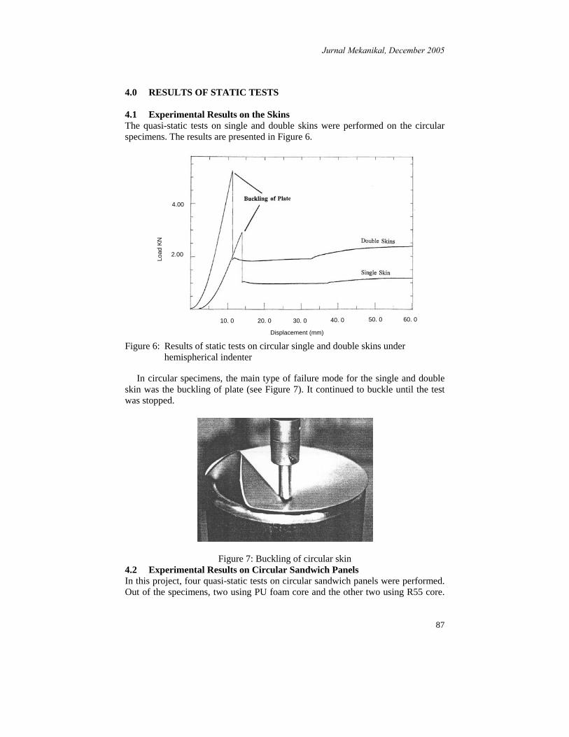
4.0 RESULTS OF STATIC TESTS 4.1 Experimental Results on the Skins The quasi-static tests on single and double skins were performed on the circular specimens. The results are presented in Figure 6.
Figure 6: Results of static tests on circular single and double skins under
hemispherical indenter
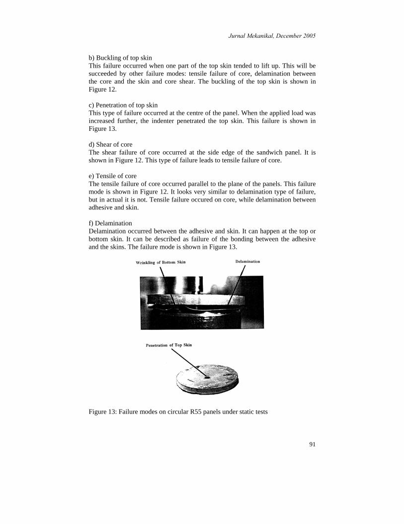
In circular specimens, the main type of failure mode for the single and double skin was the buckling of plate (see Figure 7). It continued to buckle until the test was stopped.
Figure 7: Buckling of circular skin 4.2 Experimental Results on Circular Sandwich Panels In this project, four quasi-static tests on circular sandwich panels were performed. Out of the specimens, two using PU foam core and the other two using R55 core.
4.00
2.00
10. 0 20. 0 30. 0 40. 0 50. 0 60. 0
Displacement (mm)
Load
KN

Jurnal Mekanikal, December 2005
88
Then, one of the specimens that using PU foam was loaded with flat indenter and the other one with hemispherical indenter and so thus the R55 specimen. All of the tests were carried out under cross head speed of 2 mm/min. The diameters of the flat and the hemispherical are 25 mm. The results on circular panels are presented in Figure 8-11. The respective load-deflection curves are shown with emphasis on illustrating the observed failure modes.
Figure 8: Results of static test on circular PU panel under hemispherical indenter
00
2
4
6
8
10
10 20 30 40 50 60 70
FOR
CE
(kN
)
DISPLACEMENT (mm)
Bottom Skin Displacement
Wrinkling of Bottom Skin
Shear of Core
Tensile of Core
Buckling of Top Skin
Top Skin Displacement
Figure 9: Result of static test on circular PU panel under flat indenter
Wrinkling of Bottom Skin
0 10 20 30
Shear of Core
Tensile of Core
Buckling of Top Skin
Bottom Skin Displacement
Top Skin Displacement
40 500
2
4
6
8
FOR
CE
(kN
)
DISPLACEMENT (mm)

Jurnal Mekanikal, December 2005
89
Figure 10: Result of static test on circular R55 panel under hemispherical indenter
Figure 11: Result of static test on circular R55 panel under flat indenter
Table 3 shows the data of maximum load, energy to maximum load and energy to top skin displacement of 40 mm for various samples. The energy data were found by calculating the area under the load versus displacement curves up to the specified point.
Top Skin Displacement
Wrinkling of Bottom Skin
Shear of Core
Delamination of bottom skin
Bottom Skin Displacement
0 10 20 30 40 50
2
4
6
8FOR
CE
(kN
)
DISPLACEMENT (mm)
Penetration of Top SkinLocal indentation of top skin
60 700
10
12
14
16
18
20
Penetration of Top Skin
Bottom Skin Displacement
Top Skin Displacement
0
0
2
4
6
8
10
12
14
16
18
FOR
CE
(kN
)
5 10 15 20 25 30 35 40
DISPLACEMENT (mm)

Jurnal Mekanikal, December 2005
90
Table 3: Data on circular sandwich panels under static tests
4.3 Failure Modes on Circular Panels in Quasi-Static Tests The common failure modes observed during the static tests on circular panels are: a) Local indentation This type of failure is the first to occur. The shape of the indentation is similar to the shape of the indenter. It occurred at the centre of the panel at the loading point. This failure mode is shown in Figure 12.
Specimen
Core Material
Nose shape of indenter
Max load (kN)
Disp. at max load
(mm)
Energy to max load (J)
Energy to top skin
disp. of 40 mm (J)
S1-CSP PU Hemispherical 5.84 15.33 38.3 152.7 S2-CSP PU Flat 5.82 12.00 29.9 164.9 S3-CSP R55 Hemispherical 17.20 31.15 286.3 346.3 S4-CSP R55 Flat 13.57 17.66 127.8 -
Figure 12: Failure modes on circular PU panels under static tests
Jurnal Mekanikal, December 2005
91
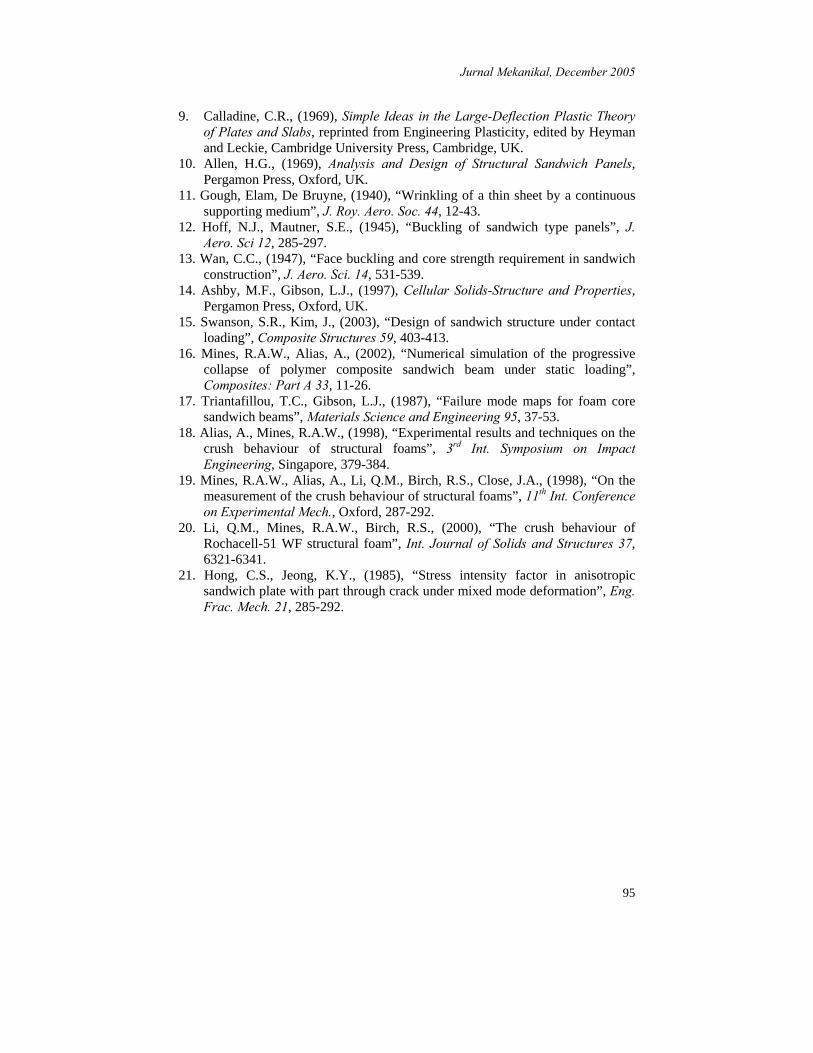
b) Buckling of top skin This failure occurred when one part of the top skin tended to lift up. This will be succeeded by other failure modes: tensile failure of core, delamination between the core and the skin and core shear. The buckling of the top skin is shown in Figure 12. c) Penetration of top skin This type of failure occurred at the centre of the panel. When the applied load was increased further, the indenter penetrated the top skin. This failure is shown in Figure 13. d) Shear of core The shear failure of core occurred at the side edge of the sandwich panel. It is shown in Figure 12. This type of failure leads to tensile failure of core. e) Tensile of core The tensile failure of core occurred parallel to the plane of the panels. This failure mode is shown in Figure 12. It looks very similar to delamination type of failure, but in actual it is not. Tensile failure occured on core, while delamination between adhesive and skin. f) Delamination Delamination occurred between the adhesive and skin. It can happen at the top or bottom skin. It can be described as failure of the bonding between the adhesive and the skins. The failure mode is shown in Figure 13.
Figure 13: Failure modes on circular R55 panels under static tests

Jurnal Mekanikal, December 2005
92
g) Wrinkling of bottom skin Wrinkling of bottom skin is a kind of failure that occurred when the load was applied further after the penetration of top skin and crushing of the core underneath the indenter. The failure mode is shown in Figure 12-13. 5.0 DISCUSSION 5.1 Static Tests on Circular Specimens 5.1.1 Behaviour of Single and Double Skins Plates From the load-deflection curves of the single skin test (see Figure 6), the load increased as the displacement of the indenter increased until reading a maximum point. The maximum load was 2.85 kN at a displacement of 12.5 mm. This was followed by a sudden drop in the load values. At that point, the plate started to buckle upwards. As the middle point of the plates started going downward, the whole plate was also trying to follow. This creates a compressive membrane action in the hoop direction of the plate. As the structure of the plate could not hold any further increase in the load it buckled outwards. This phenomena can be described as an analogy to a rod under compressive end load (Euler’s), the rod would have buckled at a certain ‘buckling load’ as the applied load increased. The behaviours of the plate in the double skin test were also similar to that of the single skin. The maximum load for the double skin test was, of course at a higher value, about 5.3 kN at a displacement of 11.5 mm. The displacement was slightly less than that of the single skin while the load was 85 % higher than that of single skin. The reason for this is that just it was harder or more difficult to deflect a thicker panel which had a higher modulus of rigidity (EI). 5.1.2 Behaviour of Circular Sandwich Panels with PU Foam under
Hemispherical and Flat Indenters The top skin displacement profile for this panel under hemispherical indenter was quite similar to that of monolithic plate (see Figure 8 and 9). As the centre point of the panel started to go downward, the whole structure of the top skin would also try to follow. This created a compressive membrane action in the hoop direction of the top skin, which then lead to the buckling of the top skin. The results of the same test under flat indenter gave quite similar curve profile. The first maximum loads for both tests were about the same at 5.8 kN but the panel under flat indenter reached its maximum load earlier at a top displacement of 12 mm while the panel under hemispherical indenter reached its first maximum point at a top displacement of 15 mm. In discussing the failure mode, as the top skin started to buckle at the first maximum point, other failure modes followed to occur. The buckling of the top skin could also be described as the ‘lifting-up’ of one part of the top skin. The tensile failure of the core was due to the ‘lifting-up’ of the top skin away from the core. The first tensile failure of the core occurred very close to the top skin. This was then followed by shear of core and tensile of core near to the bottom skin. The position of the shear of core (see Figure 12). The shear of core failure occurred at

Jurnal Mekanikal, December 2005
93
load of 4.8 kN and top skin displacement of 28 mm under hemispherical indenter, while under flat indenter happened at load of 5 kN and top skin displacement of 27 mm. As the indenter moved further downward, after the shear of core, applied load started to increase. This was due to the resistance of the whole structure to further deformation. Later, the bottom skins started to wrinkle. This was again due to the compressive membrane action in the hoop direction of the bottom skin. The direction of the wrinkling was downward because the foam gave some resistances in the upward direction. Under the hemispherical indenter it started to wrinkle at load and top skin displacement of 5.2 kN and 33 mm respectively, while under the flat indenter the failure mode started to occur at the load and displacement of 5.8 kN and 34 mm, respectively. 5.1.3 Behaviour of Circular Sandwich Panels with R55 Core under
Hemispherical and Flat Indenters The behaviours of R55 panels was quite different from that of PU panels, the first maximum loads were much higher (see Figure 10 and 11). Under hemispherical indenter, the first failure mode observed was local indentation at the point of contact on the top skin. It started to be visible at load of 12.5 kN and top skin displacement of 20 mm while under flat indenter it was quite hard to point out the starting point of local indentation. After the local indentation, the load increased almost linearly until a maximum point. That was the point where penetration of the top skin occurred. Under hemispherical indenter, it happened at load of 17 kN and top skin displacement of 32 mm while under flat indenter it failed at load of 13.5 kN and top skin displacement of 18 mm. The foams underneath the indenter were crushed more under the hemispherical indenter than that of flat indenter. The thickness of the foams, which were 27 mm originally, were reduced to about 5 mm and 15 mm under hemispherical and flat indenter respectively at the point just before the penetration of the top skin. Under flat indenter, the penetration of the top skin was associated with shear failure of the mild steel top skin. The shear failure value of a monolithic plate of
the thickness of 0.83 mm can be calculated by AP
=τ and gives a value of 207.09
MPa. The theoretical shear τ value is about 200 MPa. Meanwhile, the penetration of the top skin under hemispherical indenter could be associated with yielding. This could be explained by the extensive displacement of the top skin (32 mm) before the failure occurred. The failure modes that followed after the penetration of the top skin of core are delamination and wrinkling of the bottom skin (see Figure 13). Wrinkling of the bottom skin was the final failure mode that occurred. The failure modes of the top skin is shown in Figure 13. The Instron machine stopped automatically due to excessive ‘bang’ noise that accompanied the penetration of the top skin. 5.3 Effect of Foam’s Type on Circular Sandwich Panels Performance The higher density foam (R55) had a higher maximum load than that of the lower density foam (PU). The failure loads were also higher in R55 panels in all types of common failure between the two foams panels. These behaviours were shown in

Jurnal Mekanikal, December 2005
94
the circular sandwich panels under both hemispherical and flat indenters. The explanation was that, R55 panels had a higher modulus of rigidity (EI). The experimental value of compressive Youngs’ modulus, Ec for R55 was 32.5 MPa while for PU, Ec = 3.08 MPa. 5.4 Effect of Type of Indenter Tests under flat indenters had less value of maximum load than that of hemispherical indenters. The displacement at the respective maximum load was also less with the flat indenter. This was shown in all of the cases. This might be due to the effective area of contact during the tests. Flat indenter had a higher effective area of contact than that area and gave a lower effective load to get the same failure modes. 6.0 CONCLUSION The behaviour of the sandwich panels under static loadings depends on the property of the core materials. The R55 permits more localized failure with higher energy while the failures on PU are spread out with less energy required. The common failure modes on circular sandwich panels are local indentation, buckling of top skin, shear and tensile of cores, penetration of top skin, delamination of top or bottom skin and wrinkling of bottom skin. In the static test, panels with R55 core showed a better performance compared with panels with PU core. The use of polyester resin for bonding of the core and the skins was quite satisfactory. The test results can be used to determine behaviours in material models especially through using FEA software.
REFERENCES 1. Alias, A., (1993), Mechanical Behaviour of Sandwich Panels under Static
and Dynamic Loading, M.Sc Thesis, UMIST, UK. 2. Prager, W., (1959), An Introduction to Plasticity, Addison-Wesley Inc, UK. 3. Hodge, P.G., (1959), Plastic Analysis of Structure, McGraw-Hill Book Co.,
USA. 4. Timoshenko, Kreiger, (1970), Theory of Plates and Shells, Pregamon Press,
Oxford, UK. 5. Hopkins, H.G., Prager, W., (1953), “The load carrying capacities of circular
plates”, J. Mech. Phys. Solids 2, 1-18. 6. Hopkins, H.G., (1957), “Some remarks concerning the dependence of the
solution of plastic plate problem upon the yield criterion”, 9th Int. Congress for Appl. Mechanics, Brussels, 448-457.
7. Onat, E.T., Haythornthwaite, R.M., (1956), “The load carrying capacity of circular plates at large deflection”, J. Appl. Mech. 23, 49-55.
8. Young, A.G., (1956), The behavior and Design of Ship-plating Subjected to Combination of Normal and Edge Loads, Ph.D Thesis, University of Cambridge, UK.
Jurnal Mekanikal, December 2005
95
9. Calladine, C.R., (1969), Simple Ideas in the Large-Deflection Plastic Theory of Plates and Slabs, reprinted from Engineering Plasticity, edited by Heyman and Leckie, Cambridge University Press, Cambridge, UK.
10. Allen, H.G., (1969), Analysis and Design of Structural Sandwich Panels, Pergamon Press, Oxford, UK.
11. Gough, Elam, De Bruyne, (1940), “Wrinkling of a thin sheet by a continuous supporting medium”, J. Roy. Aero. Soc. 44, 12-43.
12. Hoff, N.J., Mautner, S.E., (1945), “Buckling of sandwich type panels”, J. Aero. Sci 12, 285-297.
13. Wan, C.C., (1947), “Face buckling and core strength requirement in sandwich construction”, J. Aero. Sci. 14, 531-539.
14. Ashby, M.F., Gibson, L.J., (1997), Cellular Solids-Structure and Properties, Pergamon Press, Oxford, UK.
15. Swanson, S.R., Kim, J., (2003), “Design of sandwich structure under contact loading”, Composite Structures 59, 403-413.
16. Mines, R.A.W., Alias, A., (2002), “Numerical simulation of the progressive collapse of polymer composite sandwich beam under static loading”, Composites: Part A 33, 11-26.
17. Triantafillou, T.C., Gibson, L.J., (1987), “Failure mode maps for foam core sandwich beams”, Materials Science and Engineering 95, 37-53.
18. Alias, A., Mines, R.A.W., (1998), “Experimental results and techniques on the crush behaviour of structural foams”, 3rd Int. Symposium on Impact Engineering, Singapore, 379-384.
19. Mines, R.A.W., Alias, A., Li, Q.M., Birch, R.S., Close, J.A., (1998), “On the measurement of the crush behaviour of structural foams”, 11th Int. Conference on Experimental Mech., Oxford, 287-292.
20. Li, Q.M., Mines, R.A.W., Birch, R.S., (2000), “The crush behaviour of Rochacell-51 WF structural foam”, Int. Journal of Solids and Structures 37, 6321-6341.
21. Hong, C.S., Jeong, K.Y., (1985), “Stress intensity factor in anisotropic sandwich plate with part through crack under mixed mode deformation”, Eng. Frac. Mech. 21, 285-292.