behaviour of a gusset plate connection · pdf filedoes not give a specific method to design...
TRANSCRIPT
Article no. 8
THE CIVIL ENGINEERING JOURNAL 1-2017
-----------------------------------------------------------------------------------------------------------------
DOI 10.14311/CEJ.2017.01.0008 77
BEHAVIOUR OF A GUSSET PLATE CONNECTION UNDER COMPRESSION
Clément Bardot1, Kamila Cábová2, Marta Kurejková2, František Wald2
1. Blaise Pascal University, Clermont-Ferrand II, France
2. Czech Technical University in Prague, Faculty of Civil Engineering, Prague,
Czech Republic
ABSTRACT
The paper presents behaviour of gusset plate connections in compression. The finite element method is employed to examine the buckling resistance of the gusset plate connections. The FE model is validated to results of physical tests and verified by an analytical solution based on existing formulas. Finally, a parametric study is performed. The studied parameters include gusset plate thickness and size, types of connection between the gusset plate and frame members and stiffeners.
KEYWORDS Gusset plate; Connection; Bracing; Buckling resistance; FEM
INTRODUCTION
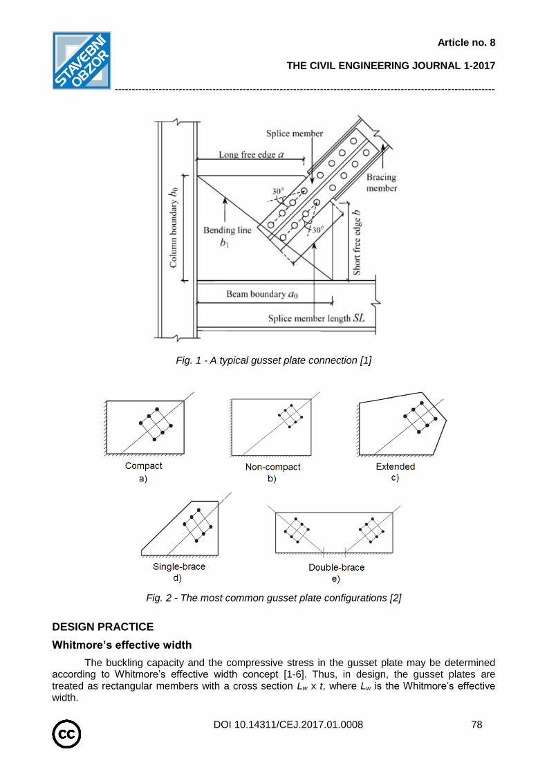
The gusset plate connections are widely used in steel structures to transfer forces from a bracing member to framing elements. A typical gusset plate connection in braced steel frame is shown in Figure 1 [1]. Depending on the particular connection detail the gusset plate can be either bolted or welded to the diagonal bracing member and to the main framing members. If the applied load to the bracing system is such that compression exists in the diagonal member, the compressive strength and stability of the gusset plate connection must be investigated. Due to the complexity of the connections, it is very difficult to evaluate the compressive strength of gusset plates.
Many documents and articles deal with the study of the gusset plates under a tension force. But few papers deal with the compression and buckling of the gusset plate. In this way, literature does not give a specific method to design the gusset plate in order to resist in compression. Actually this is engineer’s judgment, experience and practice which help to design the gusset plates.
There are several kinds of the gusset plates. However, the most usual configurations are represented in Figure 2 [2]. Schemes a, b and c represent corner-brace configurations. Compact and non-compact gusset plates are similar in the shape but for a compact configuration, the bracing member is pulled in closer to the other members of the frame. And this is not the case for the non-compact version. Thereafter, the compact configuration has been chosen for a numerical study of the behaviour of the gusset plate connections in compression.
Article no. 8
THE CIVIL ENGINEERING JOURNAL 1-2017
-----------------------------------------------------------------------------------------------------------------
DOI 10.14311/CEJ.2017.01.0008 78
Fig. 1 - A typical gusset plate connection [1]
Fig. 2 - The most common gusset plate configurations [2]
DESIGN PRACTICE
Whitmore’s effective width
The buckling capacity and the compressive stress in the gusset plate may be determined according to Whitmore’s effective width concept [1-6]. Thus, in design, the gusset plates are treated as rectangular members with a cross section Lw x t, where Lw is the Whitmore’s effective width.
Article no. 8
THE CIVIL ENGINEERING JOURNAL 1-2017
-----------------------------------------------------------------------------------------------------------------
DOI 10.14311/CEJ.2017.01.0008 79
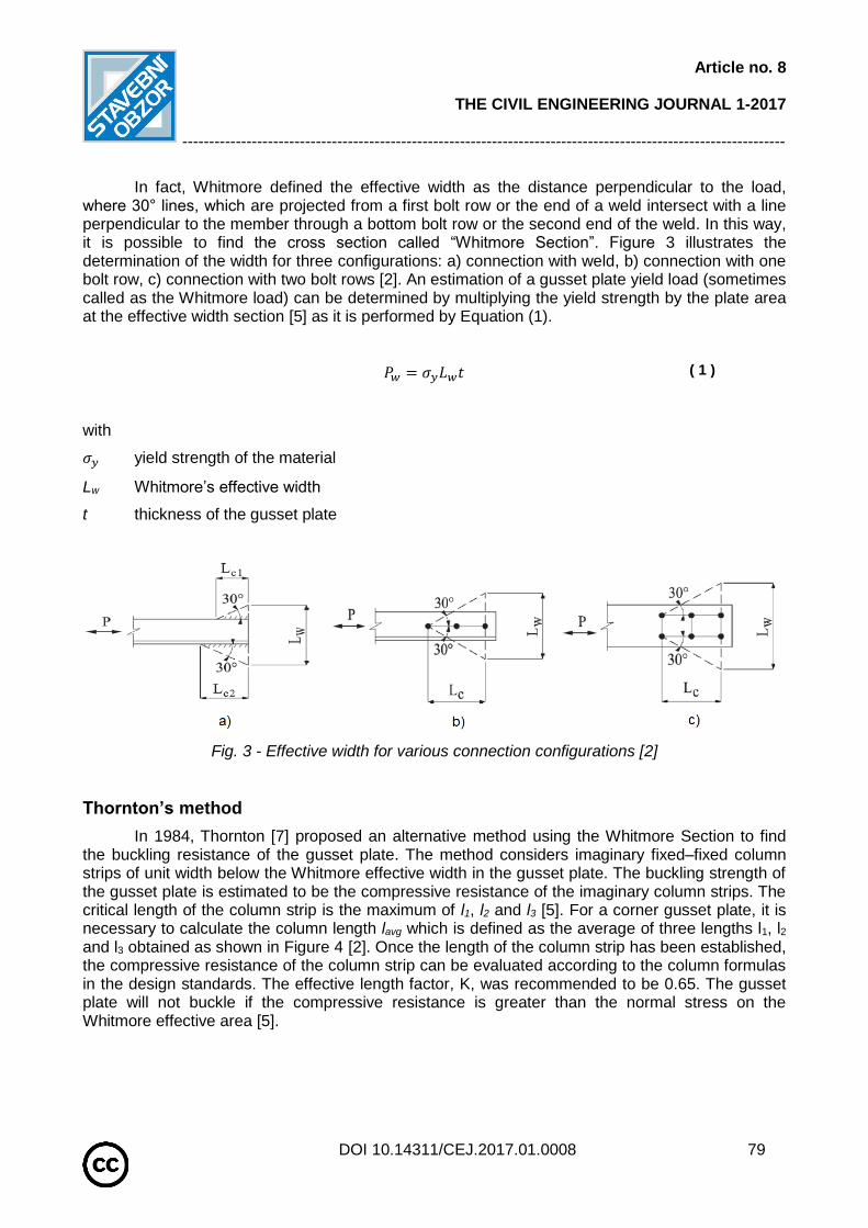
In fact, Whitmore defined the effective width as the distance perpendicular to the load, where 30° lines, which are projected from a first bolt row or the end of a weld intersect with a line perpendicular to the member through a bottom bolt row or the second end of the weld. In this way, it is possible to find the cross section called “Whitmore Section”. Figure 3 illustrates the determination of the width for three configurations: a) connection with weld, b) connection with one bolt row, c) connection with two bolt rows [2]. An estimation of a gusset plate yield load (sometimes called as the Whitmore load) can be determined by multiplying the yield strength by the plate area at the effective width section [5] as it is performed by Equation (1).
𝑃𝑤 = 𝜎𝑦𝐿𝑤𝑡
( 1 ) – Whitmore
load 𝑷𝒘
with
𝜎𝑦 yield strength of the material
Lw Whitmore’s effective width
t thickness of the gusset plate
Fig. 3 - Effective width for various connection configurations [2]
Thornton’s method
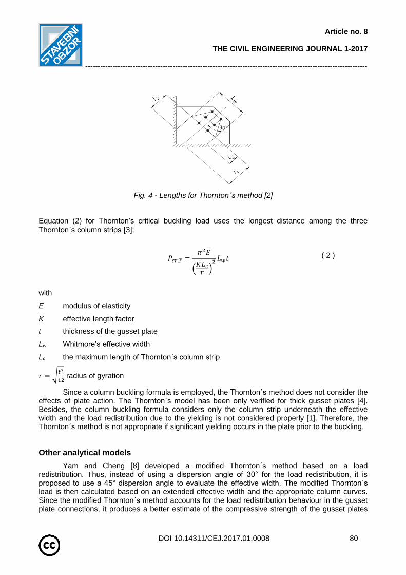
In 1984, Thornton [7] proposed an alternative method using the Whitmore Section to find the buckling resistance of the gusset plate. The method considers imaginary fixed–fixed column strips of unit width below the Whitmore effective width in the gusset plate. The buckling strength of the gusset plate is estimated to be the compressive resistance of the imaginary column strips. The critical length of the column strip is the maximum of l1, l2 and l3 [5]. For a corner gusset plate, it is necessary to calculate the column length lavg which is defined as the average of three lengths l1, l2 and l3 obtained as shown in Figure 4 [2]. Once the length of the column strip has been established, the compressive resistance of the column strip can be evaluated according to the column formulas in the design standards. The effective length factor, K, was recommended to be 0.65. The gusset plate will not buckle if the compressive resistance is greater than the normal stress on the Whitmore effective area [5].
Article no. 8
THE CIVIL ENGINEERING JOURNAL 1-2017
-----------------------------------------------------------------------------------------------------------------
DOI 10.14311/CEJ.2017.01.0008 80
Fig. 4 - Lengths for Thornton´s method [2]
Equation (2) for Thornton’s critical buckling load uses the longest distance among the three
Thornton´s column strips [3]:
𝑃𝑐𝑟,𝑇 =𝜋2𝐸
(𝐾𝐿𝑐𝑟)2 𝐿𝑤𝑡
( 2 ) – Thornton’s critical load
𝑷𝒄𝒓,𝑻
with
E modulus of elasticity
K effective length factor
t thickness of the gusset plate
Lw Whitmore’s effective width
Lc the maximum length of Thornton´s column strip
𝑟 = √𝑡2
12 radius of gyration
Since a column buckling formula is employed, the Thornton´s method does not consider the effects of plate action. The Thornton´s model has been only verified for thick gusset plates [4]. Besides, the column buckling formula considers only the column strip underneath the effective width and the load redistribution due to the yielding is not considered properly [1]. Therefore, the Thornton´s method is not appropriate if significant yielding occurs in the plate prior to the buckling.
Other analytical models
Yam and Cheng [8] developed a modified Thornton´s method based on a load redistribution. Thus, instead of using a dispersion angle of 30° for the load redistribution, it is proposed to use a 45° dispersion angle to evaluate the effective width. The modified Thornton´s load is then calculated based on an extended effective width and the appropriate column curves. Since the modified Thornton´s method accounts for the load redistribution behaviour in the gusset plate connections, it produces a better estimate of the compressive strength of the gusset plates
Article no. 8
THE CIVIL ENGINEERING JOURNAL 1-2017
-----------------------------------------------------------------------------------------------------------------
DOI 10.14311/CEJ.2017.01.0008 81
than the Thornton´s method. However, the column buckling formula is still employed and the effects of the plate action are not considered appropriately [1].
With the purpose to predict the compressive strength of the gusset plates Brown [9] was the researcher who developed an analytical model. The analytical model uses an edge-buckling equation, and is based on the Euler equation for an average buckling stress in a flat strip of plate. The model considers the plate buckling behaviour and leads to a stability design approach based on a rational plate buckling equations [1].
Other experimental and analytical studies of the compressive strength of the gusset plates were mostly done in the early twentieth century [6] and [10–14]. Most of the literature on gusset plates covers connections for steel building frames, but is relevant to steel bridges as well.
In the current design, general recommendations for buckling of steel plates are provided in the European standard EN 1993-1-5 [15]. Unfortunately, with no specific formulas to design the gusset plates loaded in compression. Therefore, a research study, which includes numerical modelling of the gusset plate behaviour in compression by finite element method is presented in this paper. Firstly, a model of the compact gusset plate connection is conducted by the finite element program Dlubal RFEM. Then results of the numerical model are validated on experimental data and compared to analytical results including Whitmore load, Thornton load and modified Thornton load. Finally, a parametric study is introduced.
EXPERIMENTAL STUDY
In this chapter an experimental programme conducted by M.C.H Yam and J.J.R Cheng [5] is introduced. A tested specimen from the experimental programme is chosen and used in the numerical study hereafter.
Description of tested specimen
Start hypothesises of the test programme were following:
Single plate gusset connections of a braced steel frame were considered; Three gusset plate thickness (13,3; 9,8 and 6,5 mm) and one bracing angle (45°) were
examined; Only gusset plate with a rectangular shape with a single size of 500 mm x 400 mm was
investigated; No bending moments into beam or column.
Regardless the start hypothesises, several points had changed during experiments. For example, the bracing angle (45° and 30°), the gusset plate size (500 x 400 mm and 850 x 700 mm) and for some tests, bending moment into beams and columns was introduced.
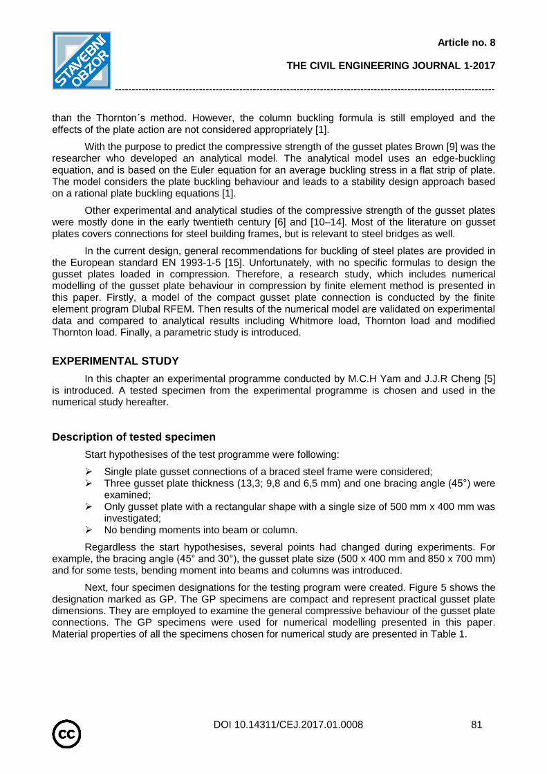
Next, four specimen designations for the testing program were created. Figure 5 shows the designation marked as GP. The GP specimens are compact and represent practical gusset plate dimensions. They are employed to examine the general compressive behaviour of the gusset plate connections. The GP specimens were used for numerical modelling presented in this paper. Material properties of all the specimens chosen for numerical study are presented in Table 1.
Article no. 8
THE CIVIL ENGINEERING JOURNAL 1-2017
-----------------------------------------------------------------------------------------------------------------
DOI 10.14311/CEJ.2017.01.0008 82
Fig. 5 - GP specimen [5]
Tab. 1 - Test results and material properties [5]
Specimen Designation
Description Plate Size
(mm x mm x mm)
Ultimate Load
(kN)
Yield Strength (MPa)
Ultimate Strength (MPa)
Modulus of
Elasticity (MPa)
GP1 13,3 mm
Gusset Plate 500 x 400 x 13,3 1956 295 501 207600
GP2 9,8 mm
Gusset Plate 500 x 400 x 9,8 1356 305 500 210200
GP3 6,5 mm
Gusset Plate 500 x 400 x 6,5 742 275 467 196000
SM 13,0 mm
Splice Member - - 285 510 199960
F
13,0 mm Flange of tee-section Splice
Member
- - 284 503 197800
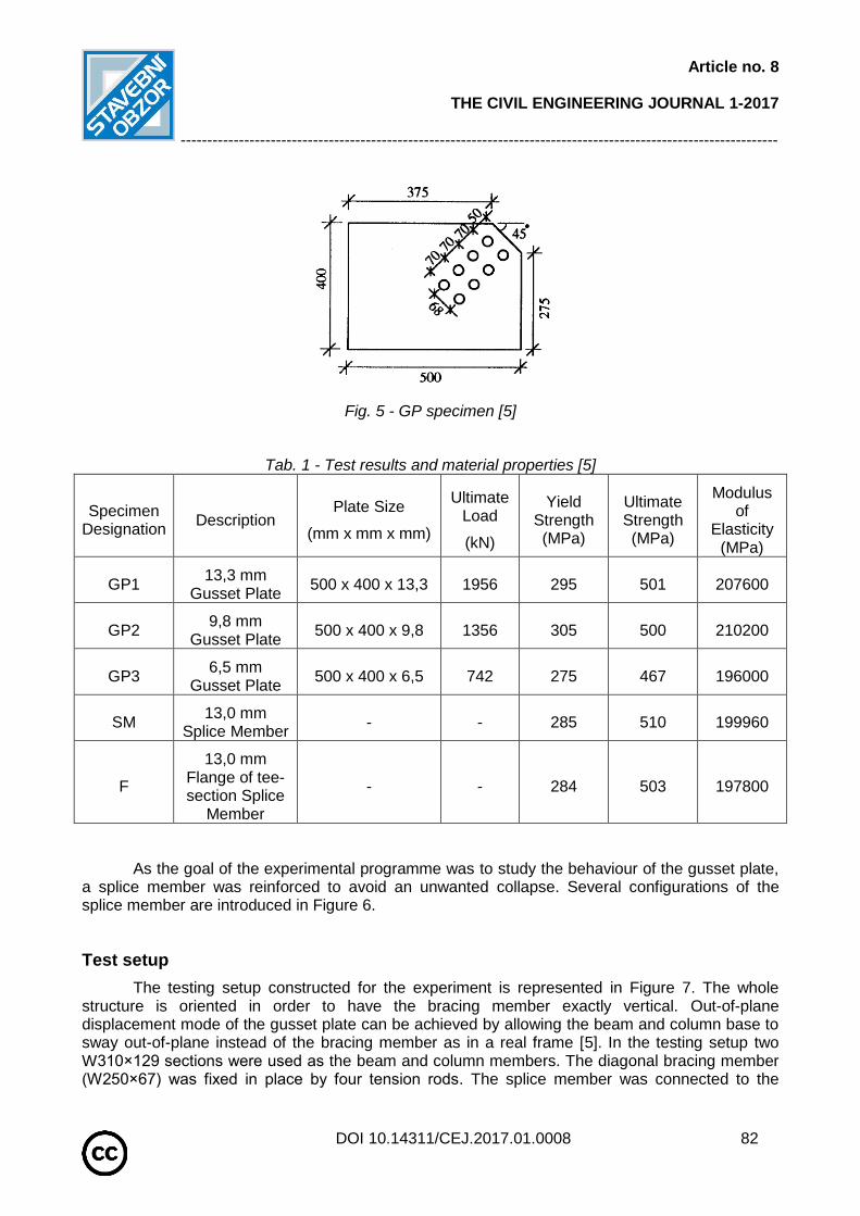
As the goal of the experimental programme was to study the behaviour of the gusset plate, a splice member was reinforced to avoid an unwanted collapse. Several configurations of the splice member are introduced in Figure 6.
Test setup
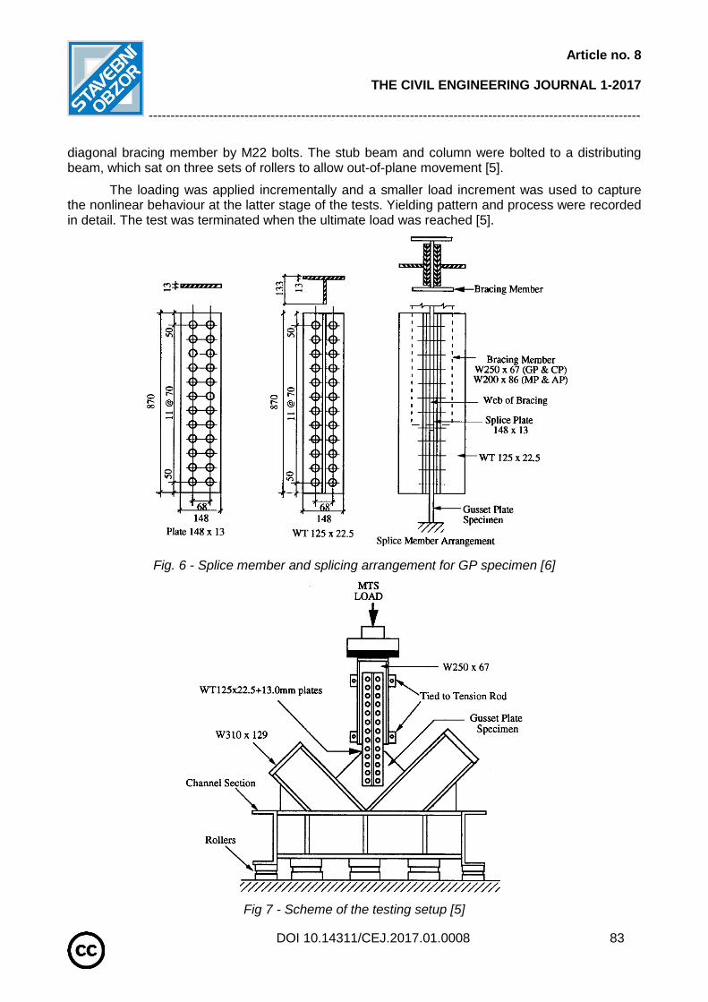
The testing setup constructed for the experiment is represented in Figure 7. The whole structure is oriented in order to have the bracing member exactly vertical. Out-of-plane displacement mode of the gusset plate can be achieved by allowing the beam and column base to sway out-of-plane instead of the bracing member as in a real frame [5]. In the testing setup two W310×129 sections were used as the beam and column members. The diagonal bracing member (W250×67) was fixed in place by four tension rods. The splice member was connected to the
Article no. 8
THE CIVIL ENGINEERING JOURNAL 1-2017
-----------------------------------------------------------------------------------------------------------------
DOI 10.14311/CEJ.2017.01.0008 83
diagonal bracing member by M22 bolts. The stub beam and column were bolted to a distributing beam, which sat on three sets of rollers to allow out-of-plane movement [5].
The loading was applied incrementally and a smaller load increment was used to capture the nonlinear behaviour at the latter stage of the tests. Yielding pattern and process were recorded in detail. The test was terminated when the ultimate load was reached [5].
Fig. 6 - Splice member and splicing arrangement for GP specimen [6]
Fig 7 - Scheme of the testing setup [5]

Article no. 8
THE CIVIL ENGINEERING JOURNAL 1-2017
-----------------------------------------------------------------------------------------------------------------
DOI 10.14311/CEJ.2017.01.0008 84
Experimental results
During all experiments an out-of-plane displacement of the test frame and the gusset plate deformations in various locations were measured. The ultimate load, which is used for the purpose of this study, was recorded and failure modes of specimens were studied. Results of the ultimate load from the experiments are summarized in Table 1.
NUMERICAL MODEL
Compact gusset plate
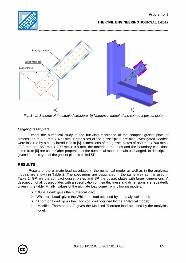
With the purpose to analyse behaviour of the gusset plate connections in compression, a numerical model using finite element software Dlubal RFEM 5.06 [16] is applied. The numerical simulation is focused on the determination of the buckling resistance of the gusset plate. Scheme of the studied structure with the splice member and the selected cross section of the bracing member is shown in Figure 8a. The model respects the geometry, material properties and boundary conditions of the specimens used in the experiments described above.
In the numerical model, 4-node quadrilateral shell elements with nodes at their corners are applied to simulate the gusset plate, the splice and bracing member. Six degrees of freedom are in every node: 3 translations (ux, uy, uz) and 3 rotations (φx, φy, φz). Material and geometric nonlinear analysis with imperfections (GMNIA) is applied. In the model materials properties of all members are created according to data given in [6], which are also introduced in Table 1. A bilinear material diagram with hardening was chosen to define materials and the von Mises yield criterion is applied. Equivalent geometric imperfections are derived from the first buckling mode and the amplitude is set according to Annex C in EN 1993-1-5 [15]. Large deformation analysis is used and the Newton-Raphson method for solving systems of equations is chosen. The number of loading steps is set to 50, the convergence criteria for tolerance to 1.0% and the maximum number of iterations to 50. The analysis stops at a certain limit of displacement.
For all calculation models, the length of finite elements is equal to 0.025 m. Boundary conditions covering different types of supports are involved in the model. The frame structure is entirely restraint at its ends of the cross-section. Thanks to this simplification the concentration on the gusset plate behaviour is allowed. Regarding the bracing member, the only allowed displacement is the axial displacement. For this, a support blocking the out-of-plane displacement uy and the displacement uz is created.
The frame members in the model are made of profiles HEA 300 of steel grade S355. These
are modelled as beam members in RFEM. The gusset plate is welded to these members on two
sides. The weld is simulated as fixed connection of the members in the model and there is no
detailed model of the weld. Stiffeners for the gusset plate free edges were not created. With the
purpose to study the buckling resistance of the gusset plate bracing IPE member was modelled as
a rigid member. A sufficient stiffness of the splice member in the model was achieved by properly
chosen geometry corresponding to the geometry of the test specimen, so there was no need to
model it as a rigid element. Bolts were modelled as a rigid surface area in order to transmit all
forces to the gusset plate. The bracing member is loaded with a point force in the direction of
member axis.
One of the numerical models is presented in Figure 8b.
Article no. 8
THE CIVIL ENGINEERING JOURNAL 1-2017
-----------------------------------------------------------------------------------------------------------------
DOI 10.14311/CEJ.2017.01.0008 85
a) b)
Fig. 8 - a) Scheme of the studied structure; b) Numerical model of the compact gusset plate
Larger gusset plate
Except the numerical study of the buckling resistance of the compact gusset plate of dimensions of 500 mm x 400 mm, larger sizes of the gusset plate are also investigated. Models were inspired by a study introduced in [5]. Dimensions of the gusset plates of 850 mm x 700 mm x 13.3 mm and 850 mm x 700 mm x 9.8 mm, the material properties and the boundary conditions taken from [5] are used. Other properties of the numerical model remain unchanged. In description given later this type of the gusset plate is called SP.
RESULTS
Results of the ultimate load calculated in the numerical model as well as in the analytical models are shown in Table 2. The specimens are designated in the same way as it is used in Table 1. GP are the compact gusset plates and SP the gusset plates with larger dimensions. A description of all gusset plates with a specification of their thickness and dimensions are repeatedly given in the table. Finally, values of the ultimate load come from following models:
“Dlubal Load” gives the numerical load;
“Whitmore Load” gives the Whitmore load obtained by the analytical model;
“Thornton Load” gives the Thornton load obtained by the analytical model;
“Modified Thornton Load” gives the Modified Thornton load obtained by the analytical
model.
Article no. 8
THE CIVIL ENGINEERING JOURNAL 1-2017
-----------------------------------------------------------------------------------------------------------------
DOI 10.14311/CEJ.2017.01.0008 86
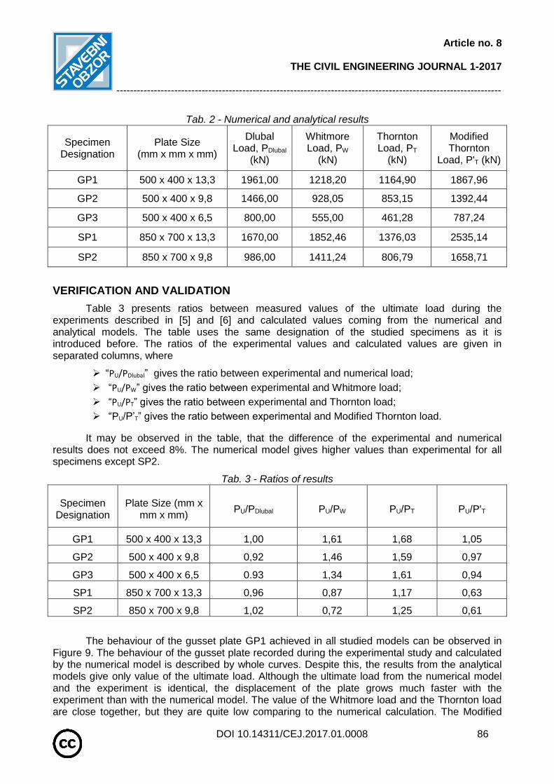
Tab. 2 - Numerical and analytical results
Specimen Designation
Plate Size (mm x mm x mm)
Dlubal Load, PDlubal
(kN)
Whitmore Load, PW
(kN)
Thornton Load, PT
(kN)
Modified Thornton
Load, P'T (kN)
GP1 500 x 400 x 13,3 1961,00 1218,20 1164,90 1867,96
GP2 500 x 400 x 9,8 1466,00 928,05 853,15 1392,44
GP3 500 x 400 x 6,5 800,00 555,00 461,28 787,24
SP1 850 x 700 x 13,3 1670,00 1852,46 1376,03 2535,14
SP2 850 x 700 x 9,8 986,00 1411,24 806,79 1658,71
VERIFICATION AND VALIDATION
Table 3 presents ratios between measured values of the ultimate load during the experiments described in [5] and [6] and calculated values coming from the numerical and analytical models. The table uses the same designation of the studied specimens as it is introduced before. The ratios of the experimental values and calculated values are given in separated columns, where
“PU/PDlubal” gives the ratio between experimental and numerical load;
“PU/PW” gives the ratio between experimental and Whitmore load;
“PU/PT” gives the ratio between experimental and Thornton load;
“PU/P’T” gives the ratio between experimental and Modified Thornton load.
It may be observed in the table, that the difference of the experimental and numerical results does not exceed 8%. The numerical model gives higher values than experimental for all specimens except SP2.
Tab. 3 - Ratios of results
Specimen Designation
Plate Size (mm x mm x mm)
PU/PDlubal PU/PW PU/PT PU/P'T
GP1 500 x 400 x 13,3 1,00 1,61 1,68 1,05
GP2 500 x 400 x 9,8 0,92 1,46 1,59 0,97
GP3 500 x 400 x 6,5 0.93 1,34 1,61 0,94
SP1 850 x 700 x 13,3 0,96 0,87 1,17 0,63
SP2 850 x 700 x 9,8 1,02 0,72 1,25 0,61
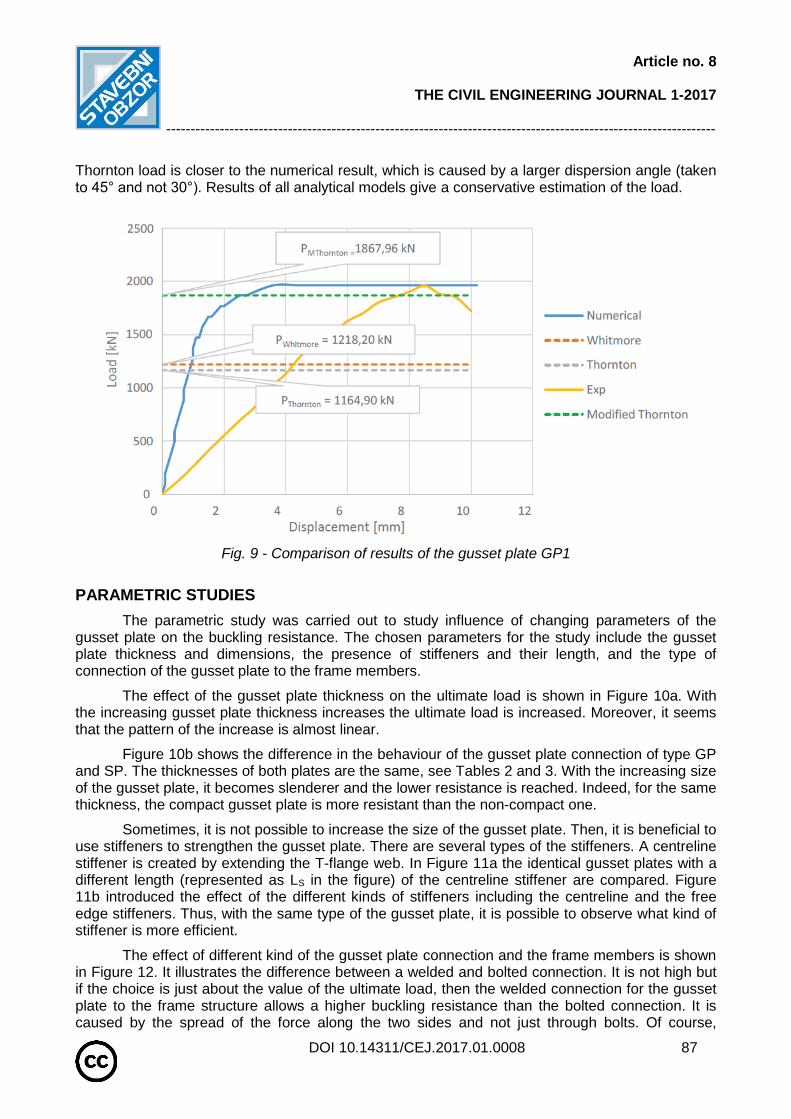
The behaviour of the gusset plate GP1 achieved in all studied models can be observed in Figure 9. The behaviour of the gusset plate recorded during the experimental study and calculated by the numerical model is described by whole curves. Despite this, the results from the analytical models give only value of the ultimate load. Although the ultimate load from the numerical model and the experiment is identical, the displacement of the plate grows much faster with the experiment than with the numerical model. The value of the Whitmore load and the Thornton load are close together, but they are quite low comparing to the numerical calculation. The Modified
Article no. 8
THE CIVIL ENGINEERING JOURNAL 1-2017
-----------------------------------------------------------------------------------------------------------------
DOI 10.14311/CEJ.2017.01.0008 87
Thornton load is closer to the numerical result, which is caused by a larger dispersion angle (taken to 45° and not 30°). Results of all analytical models give a conservative estimation of the load.
Fig. 9 - Comparison of results of the gusset plate GP1
PARAMETRIC STUDIES
The parametric study was carried out to study influence of changing parameters of the gusset plate on the buckling resistance. The chosen parameters for the study include the gusset plate thickness and dimensions, the presence of stiffeners and their length, and the type of connection of the gusset plate to the frame members.
The effect of the gusset plate thickness on the ultimate load is shown in Figure 10a. With the increasing gusset plate thickness increases the ultimate load is increased. Moreover, it seems that the pattern of the increase is almost linear.
Figure 10b shows the difference in the behaviour of the gusset plate connection of type GP and SP. The thicknesses of both plates are the same, see Tables 2 and 3. With the increasing size of the gusset plate, it becomes slenderer and the lower resistance is reached. Indeed, for the same thickness, the compact gusset plate is more resistant than the non-compact one.
Sometimes, it is not possible to increase the size of the gusset plate. Then, it is beneficial to use stiffeners to strengthen the gusset plate. There are several types of the stiffeners. A centreline stiffener is created by extending the T-flange web. In Figure 11a the identical gusset plates with a different length (represented as LS in the figure) of the centreline stiffener are compared. Figure 11b introduced the effect of the different kinds of stiffeners including the centreline and the free edge stiffeners. Thus, with the same type of the gusset plate, it is possible to observe what kind of stiffener is more efficient.
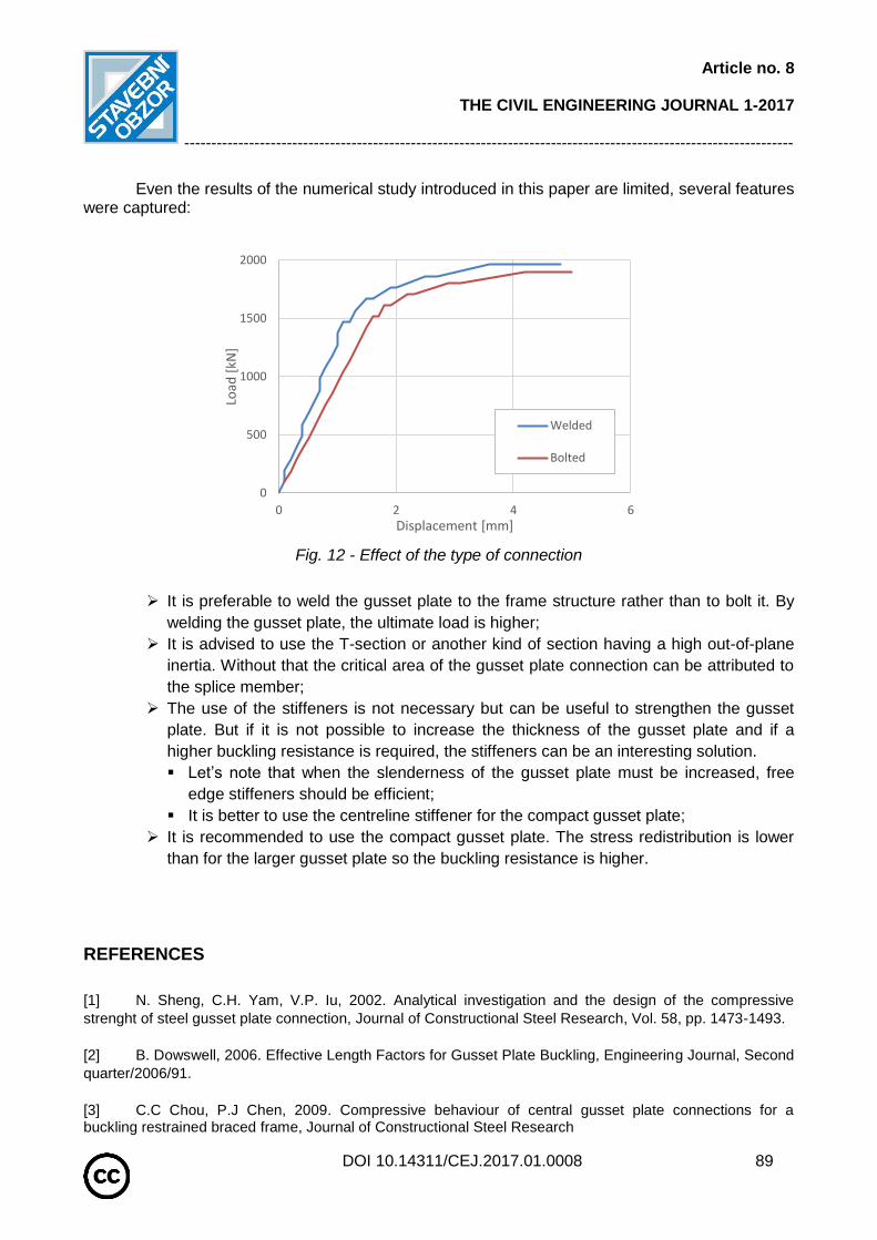
The effect of different kind of the gusset plate connection and the frame members is shown in Figure 12. It illustrates the difference between a welded and bolted connection. It is not high but if the choice is just about the value of the ultimate load, then the welded connection for the gusset plate to the frame structure allows a higher buckling resistance than the bolted connection. It is caused by the spread of the force along the two sides and not just through bolts. Of course,

Article no. 8
THE CIVIL ENGINEERING JOURNAL 1-2017
-----------------------------------------------------------------------------------------------------------------
DOI 10.14311/CEJ.2017.01.0008 88
another element can intervene in the choice between the bolt and the weld and it is the facility to install the gusset place. It is easier with the bolts than with the welds.
a) b)
Fig. 10 - a) Effect of the gusset plate thickness; b) Effect of the gusset plate size
a) b)
Fig. 11 - a) Effect of the centreline stiffener; b) Effect of stiffeners
CONCLUSION
In the paper the behaviour of the gusset plate connections in compression is studied by finite element software RFEM. The model is validated on the experimental results taken from literature. Moreover, the results of the numerical model are compared to the analytical methods given by Whitmore and Thornton. The study proved that the analytical models give a conservative estimation of the ultimate load. Nevertheless, these methods may be used in the initial phase of a design, at least as a safe initial estimation. Then, the design may be improved by the numerical modelling.
0
500
1000
1500
2000
0 2 4 6
Load
[kN
]
Displacement [mm]
GP1
GP2
GP3
0
500
1000
1500
2000
0 3 6 9 12
Load
[kN
]
Displacement [mm]
GP1
SP1
0
500
1000
1500
2000
2500
3000
3500
0 5 10 15
Load
[kN
]
Displacement [mm]
Ls = 0 mm
Ls = 50 mm
Ls = 100 mm
Ls = 150 mm0
500
1000
1500
2000
2500
3000
3500
0 5 10 15
Load
[kN
]
Displacement [mm]
Without stiffeners
Free edge stiffeners
Centerline stiffener150mm
Article no. 8
THE CIVIL ENGINEERING JOURNAL 1-2017
-----------------------------------------------------------------------------------------------------------------
DOI 10.14311/CEJ.2017.01.0008 89
Even the results of the numerical study introduced in this paper are limited, several features were captured:
Fig. 12 - Effect of the type of connection
It is preferable to weld the gusset plate to the frame structure rather than to bolt it. By
welding the gusset plate, the ultimate load is higher;
It is advised to use the T-section or another kind of section having a high out-of-plane
inertia. Without that the critical area of the gusset plate connection can be attributed to
the splice member;
The use of the stiffeners is not necessary but can be useful to strengthen the gusset
plate. But if it is not possible to increase the thickness of the gusset plate and if a
higher buckling resistance is required, the stiffeners can be an interesting solution.
Let’s note that when the slenderness of the gusset plate must be increased, free
edge stiffeners should be efficient;
It is better to use the centreline stiffener for the compact gusset plate;
It is recommended to use the compact gusset plate. The stress redistribution is lower
than for the larger gusset plate so the buckling resistance is higher.
REFERENCES
[1] N. Sheng, C.H. Yam, V.P. Iu, 2002. Analytical investigation and the design of the compressive
strenght of steel gusset plate connection, Journal of Constructional Steel Research, Vol. 58, pp. 1473-1493.
[2] B. Dowswell, 2006. Effective Length Factors for Gusset Plate Buckling, Engineering Journal, Second
quarter/2006/91.
[3] C.C Chou, P.J Chen, 2009. Compressive behaviour of central gusset plate connections for a buckling restrained braced frame, Journal of Constructional Steel Research
0
500
1000
1500
2000
0 2 4 6
Load
[kN
]
Displacement [mm]
Welded
Bolted
Article no. 8
THE CIVIL ENGINEERING JOURNAL 1-2017
-----------------------------------------------------------------------------------------------------------------
DOI 10.14311/CEJ.2017.01.0008 90
[4] D.G Lutz, R.A Laboube, 2005. Behavior of thin gusset plates in compression, Thin Walled Structure
[5] M.C.H Yam, J.J.R Cheng, 2002. Behavior and design of gusset plate connections in compression,
Journal of Constructional Steel Research, Vol. 58, pp. 1143 – 1159.
[6] J.J.R Cheng, M.C.H Yam, 1994. Elastic Buckling Strength of Gusset Plate Connections, Journal of
Structural Engineering, Vol. 120 (2), pp. 538–559.
[7] W.A. Thornton,1984. Bracing connections for heavy construction. Engineering Journal, AISC 1984;
21(3):139–48.
[8] M.C.H. Yam, J.J.R. Cheng, 1994. Analytical investigation of the compressive behaviour and strength
of steel gusset plate connections. Structural Engineering Report No. 207, University of Alberta.
[9] V.L. Brown, 1988. Stability of gusseted connections in steel structures. PhD thesis, Department of CivilEngineering, University of Delaware.
[10] J.L. Gross,1990. Experimental study of gusseted connections. Engineering Journal AISC 1990; 27(3):89–97.
[11] S.S.Walbridge, G.Y. Grondin, J.J.R. Cheng, 1998. An analytical study of the cyclic behaviour of steel gusset plate connections. In: Annual Conference of the Canadian Society for Civil Engineering (CSCE), p. 107–16.
[12] M.Couchaux, A.Rodier, 2014. Eccentric bolted gusset plate of tube: Models for resistance in compression, Eurosteel 2014, Naples. [13] The Steel Construction Institute, 2014. Joints in Steel Construction, Simple Joints to Eurocode 3, Publication P358, ISBN 978-1-85942-201-4. [14] C. Crosti, D. Duthinh, 2013. Instability of steel gusset plates in compression, Structure and Infrastructure Engineering, http://dx.doi.org/10.1080/15732479.2013.786102. [15] EN 1993-1-5, Eurocode 3: Design of steel structures - Part 1-5: Plated Structural Elements, Brussels: CEN, 2006. [16] Dlubal Software, RFEM 5.06, Student Version