behavior of hybrid concrete beams containing two … · the use of high strength concrete leads to...
TRANSCRIPT

International Journal of Science and Research (IJSR) ISSN (Online): 2319-7064
Index Copernicus Value (2015): 78.96 | Impact Factor (2015): 6.391
Volume 6 Issue 8, August 2017
www.ijsr.net Licensed Under Creative Commons Attribution CC BY
Behavior of Hybrid Concrete Beams Containing
Two Types of High Strength Concrete (HSC) and
Conventional Concrete
Suha R. Abass1, Haitham J. Abd
2
1Assistant Lecturer, Department of Civil Engineering, Engineering College, Al-Mustansireah University- Baghdad-Iraq
2Assistant Lecturer, Engineering affairs, Baghdad University- Baghdad-Iraq
Abstract: This paper is a port of a study experimental investigating the behavior of hybrid reinforced concrete beams using two types
of high strength concrete (HSC). Twelve test beams with (100 X 200 X 1100)mm dimension have been divided into four groups, each of
which consisted of three beams specimens sames in size and gross section but different in concrete type and steel bar .All beams were
tested to failure under two point loading to investigate the structural behavior . experimental results show that the use of high strength
concrete improves the beam capacity are increasing (10.41% - 48.80)% with conventional concrete in compression . the use of hybride
concrete increased the beam capacity (14.28% - 42.30%)% with conventional amerd in compression.
Keywords: Shear strength, Hybrid Concrete, High Strength Concrete.
1. Introduction
The use of high strength concrete leads to the design of
smaller sections, there by reducing the dead weight and that
is very useful for longer spans in building(1)
.
High strength concrete can be make by adding super
plasticizers (high range water) redcing admixtures to
mixture. It is sensible to merge high strength concrete and
conventional concrete in hybrid members in order to make
use of the advantages of the two materials in best ways. The
main goal of this research is to investigate the shear behavior
of hybrid concrete beams containing high strength concrete
and normal concrete. the preceding studies show that
increased shear strength by using high strength concrete.
Aamer (2)
Make an experimental investigation an shear
behavior of hybrid rectangular cross section reinforced
concrete beams strengthened with high strength concrete on
the zone of compression in the beams. Mohammed (3)
study
presents experimental and theortical investigation of flexural
behavior (strength and deflection characteristics) of hybride
rectangular beams combining convertional concrete and
reactive powder concrete. Husain(4)
and B.,A., presents
theoretical and experimental investigation of shear behavior
of hybride reinforced concrete T. beams cast monolithically.
but , the web is made with concrete differing from concrete
of tension and compression flanges. Conventional concrete
has limited low impact, ductility and little resistance to
cracking and abrasion resistance, where for we tend to the
hybrid concrete due to advances in concrete technology . it
is simple in relation make combined section which has high
ductility, high compressive strength, high tensile strength
and high ability absorption.
2. Experimental Work
2.1 Experimental Program
Four test slab groups were used in this study, each one of
them consisted of three slab specimens identical in size but
they are different in concrete type and steel bar
reinforcement. All beams in groups having specific
compressive strength 40 MPa .the diamention of the beams
are (100 x 200 x 1100) mm. all beams are reinforced by four
deformed reinforcing bar .see (table 1 ,fig 1). which made
with normal concrete and high strength concrete (100%)
(first and third group), another beams ( second and fourth
group) which made with hybrid concrete (50% normal
concrete & 50% high strength concrete( additional GL51, SP
100 )) . All beams width is (200mm), height is (100mm)
and length is (1100mm)., see Table (1) and Figure (1). Each
one of these slabs was designated in the way of refer to
concrete type and steel bar reinforcement.
Table 1: Tested Slabs Properties and Description
Group Slab
Designation Concrete type
Reinforce-
ment
Group-
A
A1 Normal concrete 100%
4ф 12
ф 6@
100 mm
c/c
A1 High strength concrete
( GL51 ) 100%
A3 High strength concrete
( SP100 ) 100%
Group-
B
B1 HSC ( GL51 ) 50% &
( SP100) 50%
4ф 12
ф 6@
100 mm
c/c
B2 HSC ( GL51 ) 50%
& NC 50%
B3 HSC ( SP100 ) 50%
& NC 50%
Group-
C
C1 Normal concrete 100%
6ф 12
ф 6@
100 mm
c/c
C2 High strength concrete
( GL51 ) 100%
C3 High strength concrete
( SP100 ) 100%
Group-
D
D1 HSC ( GL51 ) 50%
&( SP100) 50%
6ф 12
ф 6@
100 mm
c/c
D2 HSC ( GL51 ) 50%
& NC 50%
D3 % & NC 50%
HSC ( SP100 ) 50
Paper ID: 31071702 DOI: 10.21275/31071702 708

International Journal of Science and Research (IJSR) ISSN (Online): 2319-7064
Index Copernicus Value (2015): 78.96 | Impact Factor (2015): 6.391
Volume 6 Issue 8, August 2017
www.ijsr.net Licensed Under Creative Commons Attribution CC BY
Paper ID: 31071702 DOI: 10.21275/31071702 709

International Journal of Science and Research (IJSR) ISSN (Online): 2319-7064
Index Copernicus Value (2015): 78.96 | Impact Factor (2015): 6.391
Volume 6 Issue 8, August 2017
www.ijsr.net Licensed Under Creative Commons Attribution CC BY
Figure 1: Each beam was designated in a way to refer to concrete type and steel bar reinforcement
2.2 Materials
The following materials are used In manufacturing test
specimens as: (type I) ordinary Portland cement produced at
Northern cement factory (Tasluja-Bazian) in this
investigation the research use , properties of this material
comply with the Iraqi standard specification No.5/1984
requirements; and also the research used AL.ukhaider
natural sand of 4.75 mm maxim size as fine aggregates. The
grading of fine aggregate complies with the Iraqi Standard
specification No.45/1984, Crushed gravel with maximum
size of(10 mm) from AL.nibaee area. The grading of the
coarse aggregate complies with the Iraqi standard
specification No.45/1984 and also the research used high
water reducer super plasticizer (GL51) (SP100) and that
clean tap water was used for curing and mixing. The
concrete mix proportions are presented in Table (2).
The steel reinforcement have (4ф 12 & 4ф 16) and (ф 6) in
diameter at (100 mm) c/c spacing in each way for all groups.
A clear cover of (5mm) was but below the mesh. For all
slabs, the steel reinforcement were designed to ensure the
tested specimens to fail either by punching shear or flexural.
Paper ID: 31071702 DOI: 10.21275/31071702 710

International Journal of Science and Research (IJSR) ISSN (Online): 2319-7064
Index Copernicus Value (2015): 78.96 | Impact Factor (2015): 6.391
Volume 6 Issue 8, August 2017
www.ijsr.net Licensed Under Creative Commons Attribution CC BY
Table 2: Concrete Mixes Mix
proportions
Water
(l/m3)
Cement
(kg/m3)
Sand
(kg/m3)
Gravel
(kg/m3)
Superplasticizers
(l/m3)
Normal conc. 180 450 610 1220 0
HSC 181.16 500 640 1280 5 (Gl)
HSC 181.16 500 640 1280 5( Sp 100)
2.3 Instrumentation and Measurements Test
The research used hydraulic universal testing machine (MFL
system) to test the slabs specimens as well as control
specimens. Central deflection has been measured by means
of (0.01mm) accuracy dial gauge (ELE type) and (30mm)
capacity. The dial gauges were placed underneath at the
center of the bottom face. All tests were made in the
structures laboratory of in Al-Mustansiriya University,
college of Engineering, Baghdad, Iraq.
2.4 Results of Specimens Test
Test results of mechanical properties of hardened concrete
specimens are showing in Table (3). Compressive strength
was carried out on (100x100x100mm) cubes and (150 x
300) mm cylinders.
Table 3: Mechanical Properties of Concrete Mix
Designation
Property (MPa)
Cube Compressive
strength (fcu)*
Cylinder Compressive
strength (fcu)*
A1 40 30
A2 38 32
A3 41 33
B1 38 31
B2 40 33
B3 42 31
C1 39 34
C2 38 30
C3 40 34
D1 42 31
D2 41 34
D3 39 32
* Three samples average of (per mix) by using
(150x150x150mm) cubes.
** Three samples average of (per mix) by using
(150x300mm) cylinder.
2.5 Procedure Test
Figure (2) show the setup of tested specimens. All beams
specimens were tested by using the universal testing
machine (MFL system) with monotonic loading to ultimate
states. The tested beams were simply supported and loaded
with a load of single-point. The beams have been tested at
(28) days age. The centerline, supports, point load and dial
gauge were in their best locations. Because that the beam
specimens were placed on the testing machine and adjusted.
Loading was applied slowly in successive increments;.
observations and measurements were recorded for the mid-
span deflection and crack development and propagation on
the beam surface , At the end of each load increment.
smaller increments were applied until failure When the beam
reached advanced stage of loading, where the deflections
increased very fast and the load indicator stopped recording
anymore without any increase in applied load.
crack pattern were marked by a pencil at each load
increment.
Figure 2: Setup of Tested Specimens
3. Results and Discussion
3.1 General Behavior
The test results of all (12) beams included first crack and
ultimate load and failure mode are listed in Table (4) and
photographs (1-12).
Table 4: Tested beams Cracked load, Ultimate and type of
Failure
Group Slab
Designation
First crack
load (Vcr)
(KN)
Ultimate
Load(Vc)
(KN)
Vcr/Vc Failure
mode
Group-A
A1 25 150 0.166 Shear
A2 66 175 0.377 Shear
A3 66 260 0.253 Shear
Group-B
B1 50 200 0.250 Shear
B2 89 225 0.395 Shear
B3 60 395 0.151 Shear
Group-C
C1 79 215 0.367 Shear
C2 45 240 0.187 Shear
C3 165 420 0.392 Shear
Group-D
D1 65 250 0.392 Shear
D2 100 290 0.344 Shear
D3 185 450 0.411 Shear
3.2 Failure Mode and Crack Pattern
Layout of the diagonal crack patterns which leads to shear
failure can be shown in Figure (3). There are numbers
nearby the cracks which representing the load when the
cracks have reached to the indicating position. Moreover,
Figure(4) illustrating the crack patterns photographs of all
project tested beams after the final failure. Generally, similar
linear behaviour will be exhibited by all the tested beams
from the initial loading up to the load causing failure. Also,
in all the beams, no observation of the vertical flexural
cracks will be noticed in the region of pure bending between
the two points loads for each load stage. In general, the
Paper ID: 31071702 DOI: 10.21275/31071702 711

International Journal of Science and Research (IJSR) ISSN (Online): 2319-7064
Index Copernicus Value (2015): 78.96 | Impact Factor (2015): 6.391
Volume 6 Issue 8, August 2017
www.ijsr.net Licensed Under Creative Commons Attribution CC BY
progression for cracking of each specimen can be
summarized as follows:
Through the early stages of loading, the beams are cracks
free. With further increase in load, there will a formation of
an inclined tensile crack in one of the shear spans between
point load and support which distribute above the
longitudinal reinforcement, while a curved one will be
formed toward the loading point. Later, the diagonal crack
will be developed from the higher point of this crack in the
shear span and will extend towards the point load with the
increasing load. Ultimately, a faster extension of the
diagonal crack will be taken place in the compressive zone
towards the point load and horizontally towards the position
of the tension steel leading to failure. Progressing behaviour
of all beams is managed by micro-cracking, which
particularly associated with the interfacial transition zone.
Thus, using chemical and mineral admixtures,.
Subsequently, good results of tensile strength can be
expected. The last failure behaviour can be considered as a
mode of diagonal tension failure. The shear cracks
development is sudden and immediately followed by a
severe and totally destructive shear failure.
Figure 3: Crack pattern specimens at failure shear and
flexural (A,B,C,D)
3.3 Ultimate Loads
This section of the research is important to find the
difference in ultimate load capacity when using three types
of concrete, beams which made with normal concrete and
high strength concrete (100%) (first and third group),
another beams ( second and fourth group) which made with
hybrid concrete (50% normal concrete & 50% high strength
concrete( additional GL51, SP 100 )).
For group (A&B) there is an increasing in ultimate load
capacity about ( A2 (14.28%) & A3(42.30%) with regard to
A1) (( B2 (11.11%) & B3(49.36%)) with regard to B1 .
This experimental revealed that the ultimate load capacity
increase with the addition of super plasticizers to the mix of
concrete.
For group (C&D) there is an increasing in ultimate load
capacity about (C2 (10.41%) decreasing & C3(48.80%)
increasing with regard to C1), (D2 (13.79%) decreasing &
D3(44.44%) increasing with regard to D1).
Paper ID: 31071702 DOI: 10.21275/31071702 712
International Journal of Science and Research (IJSR) ISSN (Online): 2319-7064
Index Copernicus Value (2015): 78.96 | Impact Factor (2015): 6.391
Volume 6 Issue 8, August 2017
www.ijsr.net Licensed Under Creative Commons Attribution CC BY
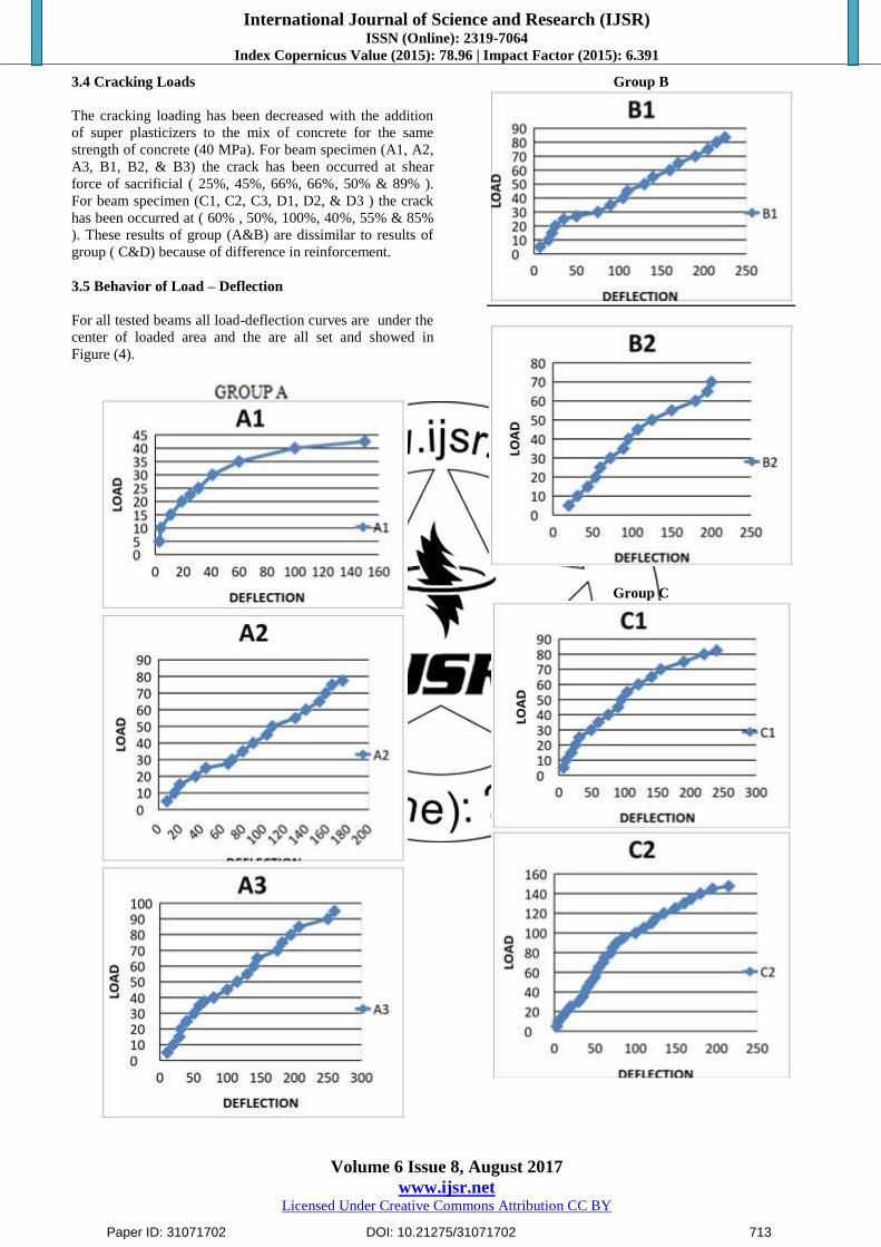
3.4 Cracking Loads
The cracking loading has been decreased with the addition
of super plasticizers to the mix of concrete for the same
strength of concrete (40 MPa). For beam specimen (A1, A2,
A3, B1, B2, & B3) the crack has been occurred at shear
force of sacrificial ( 25%, 45%, 66%, 66%, 50% & 89% ).
For beam specimen (C1, C2, C3, D1, D2, & D3 ) the crack
has been occurred at ( 60% , 50%, 100%, 40%, 55% & 85%
). These results of group (A&B) are dissimilar to results of
group ( C&D) because of difference in reinforcement.
3.5 Behavior of Load – Deflection
For all tested beams all load-deflection curves are under the
center of loaded area and the are all set and showed in
Figure (4).
Group B
Group C
Paper ID: 31071702 DOI: 10.21275/31071702 713

International Journal of Science and Research (IJSR) ISSN (Online): 2319-7064
Index Copernicus Value (2015): 78.96 | Impact Factor (2015): 6.391
Volume 6 Issue 8, August 2017
www.ijsr.net Licensed Under Creative Commons Attribution CC BY
Group D
Figure 4: Load-Deflection Curves Group (A, D, C, D)
3.6 Effect of bar daimeter in Ultimate Capacity
According to the experimental results, the ultimate load
capacity of tested specimens reinforced by 16 mm C1
increased by (30.23%) in comparison with beam A1
reinforced by 12 mm , for the beam specimen C2 increased
by about (27,08%) in comparison with beam A2, C3
increased by about (30.09%) in comparison with beam A3.
But the ultimate load capacity of tested specimens reinforced
by 16 mm D1 increased by (20%) in comparison with beam
B1, for the beam specimen D2 increased by about (22.14%)
in comparison with beam B2, D3 increased by about
(12.22%) in comparison with beam B3 As shown in Fig. (5).
Group A, C
Group B, D
Paper ID: 31071702 DOI: 10.21275/31071702 714

International Journal of Science and Research (IJSR) ISSN (Online): 2319-7064
Index Copernicus Value (2015): 78.96 | Impact Factor (2015): 6.391
Volume 6 Issue 8, August 2017
www.ijsr.net Licensed Under Creative Commons Attribution CC BY
Figure 5: Effect of bar diameter in Ultimate Capacity
GROUP (A.B.C.D)
3.7 Effect of concerte type in Ultimate Capacity
The experimental results of ultimate load capacity of tested
specimens are showed in Fig. (6). For the steel bar
reinforcement (Ø 12 mm) with different concrete type ( CC
& HSC ) ( HSC with GL51 & HSC with Ssp100 ). The
results showed that the ultimate load capacity of tested
specimens A2 , A3 was increased with this retio (14.28% &
42.30%) in comparison with beam A1. B2 , B3 increased by
(11.11% & 49.36%) in comparison with beam B1. In group
C & D with steel bar diameter (Ø 16 mm), the results
showed increased in ultimate load capacity of tested
specimens for the beam specimen C2 increased by about
(10.41%) in comparison with beam C1, D2 increased by
about (13.79%) in comparison with beam D1 , but
increasing in ultimate load capacity of tested specimens for
the beam specimen C3 increased by about (48.80%) in
comparison with slab C1, D3 increased by about (44.44%)
in comparison with beam D1
Group A
Group B
Group C
Paper ID: 31071702 DOI: 10.21275/31071702 715

International Journal of Science and Research (IJSR) ISSN (Online): 2319-7064
Index Copernicus Value (2015): 78.96 | Impact Factor (2015): 6.391
Volume 6 Issue 8, August 2017
www.ijsr.net Licensed Under Creative Commons Attribution CC BY
Group D
Figure 6: Effect of concrete type in ultimate capacity Group
(A, B, C, D)
4. Conclusions
1) For specimens which that made with hybrid high strength
concrete the ultimate capacity of tested specimens
increased with (10.41% - 48.80%) in comparison with
normal concrete.
2) The ultimate capacity of tested specimens increased for
beams which made with HSC by about (14.28% -
42.30%) in comparison with normal concrete.
3) For specimens reinforced with steel bar Ø 12mm , the
results of ultimate load capacity showed increasing for
specimens made with hybrid and high strength concrete
in comparison with normal concrete. But for specimens
reinforced with steel bar Ø 16 mm, the results of ultimate
load capacity showed increasing for specimens made
with hybrid concrete (normal & SP100) but increasing
for specimens made with hybrid concrete (normal &
GL51 ).
4) The failure perimeter increased significantly with
specimens which made with high strength concrete and
hybrid concrete in comparison with normal concrete.
5) The amount of steel reinforced beams does not have a
significant effect on the value of the first cracking load
but it has effectiveness on the value of the ultimate load.
References
[1] Aamer N. A., "Shear Behavior of hybrid Reinforced
Concrete beams ", AL.Qadisiya Journal for Engineering
sciences , vol.(4),no.(1), 2011.
[2] ACI committee 318 ,"Building Code Requirements for
structural concrte (ACI318-M95)",American Concrete
Institute , Detroit, USA,1995.
[3] ACI committee 363 ,"Guide to quality control and testing
of high strength concrete (ACI363,2R-98)",American
Concrete Institute , Detroit, USA,1998.
[4] ASTM, "Standard Specification for chemical admixtures
for concrete ", (ASTM C494-05), American Society for
Testing and Materials, 2005.
[5] ASTM, "Test method for compressive strength of
cylindrical concrete specimens ", (ASTM C39-96),
American Society for Testing and Materials, 1996.
[6] Husain, M., Bayan, S., and Ali, H."Shear behavior of
reinforced concrete T.Beams containing steel fiber
reinforced concrete (SFRC) and high strength concrete
(HSC) " Journal of Engineering and development, vol.10,
no.4,December (2006),ISSN1813-T822.
[7] Mohammed , H.M., C.P., "Flexural behavior of hybrid
beams containing reactive powder concrete and
conventional concrete", doctoral Thesis,AL.Mustansiriya
University , 2013.
[8] Newman, J., and choo,B.S., "Advanced concete
Technology" Ist Edition , Elsevier Ltd., UK,2003.
Paper ID: 31071702 DOI: 10.21275/31071702 716