before using the product,
TRANSCRIPT
BEFORE USING THE PRODUCT, BE SURE TO READ THE FOLLOWING:To maintain safety:
To ensure the safe operation of this product, be sure to read the following before usage.The following instructions are intended for the users, operators and the personnel in charge of theoperation of the product. After carefully reading and sufficiently understanding the warningdisplays and cautions, handle the product appropriately. Be sure to keep this manual close to theproduct or in a convenient place for future reference.
Herein, explanations which require special attention are enclosed with dual lines. Depending onthe potentially hazardous degrees, the terms of DANGER, WARNING, CAUTION, etc. are used.Be sure to understand the contents of the displays before reading the text.
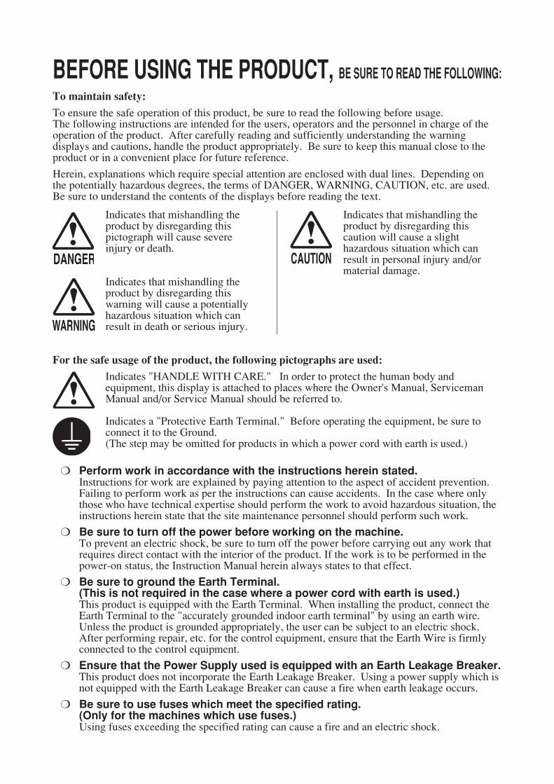
Indicates that mishandling theproduct by disregarding thispictograph will cause severeinjury or death.
Indicates that mishandling theproduct by disregarding thiswarning will cause a potentiallyhazardous situation which canresult in death or serious injury.
Indicates that mishandling theproduct by disregarding thiscaution will cause a slighthazardous situation which canresult in personal injury and/ormaterial damage.
For the safe usage of the product, the following pictographs are used:
Indicates "HANDLE WITH CARE." In order to protect the human body andequipment, this display is attached to places where the Owner's Manual, ServicemanManual and/or Service Manual should be referred to.
Indicates a "Protective Earth Terminal." Before operating the equipment, be sure toconnect it to the Ground.(The step may be omitted for products in which a power cord with earth is used.)
❍ Perform work in accordance with the instructions herein stated.Instructions for work are explained by paying attention to the aspect of accident prevention.Failing to perform work as per the instructions can cause accidents. In the case where onlythose who have technical expertise should perform the work to avoid hazardous situation, theinstructions herein state that the site maintenance personnel should perform such work.
❍ Be sure to turn off the power before working on the machine.To prevent an electric shock, be sure to turn off the power before carrying out any work thatrequires direct contact with the interior of the product. If the work is to be performed in thepower-on status, the Instruction Manual herein always states to that effect.
❍ Be sure to ground the Earth Terminal.(This is not required in the case where a power cord with earth is used.)This product is equipped with the Earth Terminal. When installing the product, connect theEarth Terminal to the "accurately grounded indoor earth terminal" by using an earth wire.Unless the product is grounded appropriately, the user can be subject to an electric shock.After performing repair, etc. for the control equipment, ensure that the Earth Wire is firmlyconnected to the control equipment.
❍ Ensure that the Power Supply used is equipped with an Earth Leakage Breaker.This product does not incorporate the Earth Leakage Breaker. Using a power supply which isnot equipped with the Earth Leakage Breaker can cause a fire when earth leakage occurs.
❍ Be sure to use fuses which meet the specified rating.(Only for the machines which use fuses.)Using fuses exceeding the specified rating can cause a fire and an electric shock.

❍ Specification changes (removal of equipment, conversion and addition) notdesignated by SEGA are not allowed.The parts of the product include warning labels for safety, covers for personal protection, etc.It is very hazardous to operate the product by removing parts and/or modifying the circuits.Should doors, lids and protective parts be damaged or lost, refrain from operating the product,and contact where the product was purchased from or the office herein stated.SEGA shall not be held responsible for any accidents, compensation for damage to a thirdparty, resulting from the specifications not designated by SEGA.
❍ Ensure that the product meets the requirements of appropriate ElectricalSpecifications.Before installing the product, check for Electrical Specifications. SEGA products have anameplate on which Electrical Specifications are described. Ensure that the product iscompatible with the power supply voltage and frequency requirements of the location. Usingany Electrical Specifications different from the designated Specifications can cause a fire andan electric shock.
❍ Install and operate the product in places where appropriate lighting isavailable, allowing warning labels to be clearly read.To ensure safety for the customers, labels and printed instructions describing potentiallyhazardous situations are applied to places where accidents can be caused. Ensure that wherethe product is operated has sufficient lighting allowing the warnings to be read. If any label ispeeled off, apply it again immediately. Please place an order with where the product waspurchased from or the office herein stated.
❍ When handling the monitor, be very careful.(Applies only to the product with a monitor.)Some of the monitor (TV) parts are subject to high tension voltage. Even after turning off thepower, some portions are still subject to high tension voltage sometimes. Monitor repair andreplacement should be performed only by those technical personnel who have knowledge ofelectricity and technical expertise.
❍ Be sure to adjust the monitor/projector properly.(Applies only to the product with a monitor/projector.)Do not operate the product leaving on-screen flickering or blurring as it is. Using the productwith the monitor/projector not properly adjusted may cause dizziness or a headache to anoperator, a player, or the customers.
❍ When transporting or reselling this product, be sure to attach this manual tothe product.In the case where commercially available monitors and printers are used in this product, onlythe contents relating to this product are explained herein. Some commercially availableequipment has functions and reactions not stated in this manual. Read this manual togetherwith the specific Instruction Manual of such equipment.
* Descriptions herein contained may be subject to improvement changes without notice. * The contents described herein are fully prepared with due care. However, should any
question arise or errors be found, please contact SEGA.
INSPECTIONS IMMEDIATELY AFTER TRANSPORTING THE PRODUCT TO THE LOCATIONNormally, at the time of shipment, SEGA products are in a status allowing for usage immediatelyafter transporting to the location. Nevertheless, an irregular situation may occur duringtransportation. Before turning on the power, check the following points to ensure that the producthas been transported in a satisfactory status.❐ Are there any dented portions or defects (cuts, etc.) on the external surfaces of the cabinet?❐ Are Casters and Adjusters damaged?❐ Do the power supply voltage and frequency requirements meet with those of the location?❐ Are all wiring connectors correctly and securely connected? Unless connected in the correct
way, connector connections can not be made accurately. Do not insert connectors forcibly.❐ Do power cords have cuts and dents?❐ Do the fuses used meet specified ratings? Is the Circuit Protector in an energized status?❐ Are all accessories available?❐ Can all Doors and Lids be opened with the Accessory Keys? Can Doors and Lids be firmly
closed?

TAB
LE OF C
ON
TENTS
i
TABLE OF CONTENTS
BEFORE USING THE PRODUCT, BE SURE TO READ THE FOLLOWING:TABLE OF CONTENTS ....................................................................................... iINTRODUCTION ................................................................................................ iii
1 HANDLING PRECAUTIONS ......................................................................... 1 2 PRECAUTIONS REGARDING INSTALLATION LOCATION ........................ 2 2-1 LIMITATIONS OF USAGE ................................................................................................2 3 PRECAUTIONS REGARDING PRODUCT OPERATION ............................. 3 4 PART DESCRIPTIONS .................................................................................. 5 5 ACCESSORIES ............................................................................................. 7 6 ASSSEMBLY AND INSTALLATION .............................................................. 8 6-1 INSTALLATION ................................................................................................................9 6-2 TURNING ON THE POWER (SOFTWARE INSTALLATION) ........................................10 6-3 CHECKING ASSEMBLY (SETUP) .................................................................................10
7 PRECAUTIONS WHEN MOVING THE MACHINE ...................................... 13 8 GAME DESCRIPTION ................................................................................. 14 8-1 GAME OUT LINE ............................................................................................................14 8-2 HOW TO CONTROL .......................................................................................................15 8-3 HOT TO FISH ................................................................................................................17 8-4 BONUS GAME ...............................................................................................................18 8-5 SPECIAL LURE ..............................................................................................................19 8-6 GAME FLOW ..................................................................................................................20
ii
TAB
LE OF C
ON
TENTS
9 SYSTEM MENU ........................................................................................... 22 9-1 SWITCH UNIT AND COIN METER ................................................................................23 9-2 SYSEM MENU ................................................................................................................24 9-3 TEST MODE ...................................................................................................................25 9-4 CONFIGULRATION .......................................................................................................27 9-5 BOOKKEEPING .............................................................................................................29 9-6 BACKUP CLEAR ...........................................................................................................3110 TOURNAMENT ............................................................................................ 33 10-1 TOURNAMENT .............................................................................................................33 10-2 START DAY, END DAY .................................................................................................36 10-3 SELECT MARCHANDISE ............................................................................................37 10-4 ADVERTIZE SCREEN EDITOR ..................................................................................38 10-5 PRITABLE TEXT EDITOR ............................................................................................39 10-6 PLAY LOG ....................................................................................................................39 10-7 ABOUT PRINTER .........................................................................................................40
11 PERIODIC INSPECTION ............................................................................. 45 12 TROUBLESHOOTING ................................................................................. 46 12-1 TROUBLESHOOTING (WHEN NO ERROR MESSAGE IS SHOWN) .........................46 12-2 ERROR CODE ..............................................................................................................46
13 GAME BOARD ............................................................................................ 47
14 CABINET PARTS DESCRIPTION ............................................................... 51 15 PARTS LIST, CONTROLLER ...................................................................... 52 16 WIRE COLOR CODE TABLE ...................................................................... 53 17 WIRING DIAGRAM ...................................................................................... 54
181LINCENSE MARK....................................................................................... 56191PRINTER KIT (OPTION) ............................................................................. 57
INTR
OD
UC
TION
iii
INTRODUCTIONThis manual is intended to provide detailed descriptions together with all the necessary information covering the general operation of electronic assemblies, electro-mechanicals, servicing control, spare parts, etc. for the product, “SEGA BASS FISHING CHALLENGE, CVT KIT”.This manual is intended for the owners, personnel and managers in charge of operation of the product. Operate the product after carefully reading and sufficiently understanding the instructions. In the unlikely event that the product does not function correctly, DO NOT allow anyone other than a technician to touch the internal system. Turn off the power to the machine, making sure to unplug the electrical cord from the outlet, and contact the office listed below or the point of purchase for this product.Use of this product is unlikely to cause physical injuries or damage to property. However, points that require special attention are indicated by bold text, the word “IMPORTANT” and the symbol below.
Sega Amusements U.S.A., Inc.800 Arthur Avenue, Elk Grove Village, IL 60007-5215, U.S.A.
TEL: 1-847-364-9787TOLL FREE: 1-888-877-2669FAX: 1-847-427-1065
Indicates important information that, if ignored, may result in the mishandling of the product and cause faulty operation or damage to the product.
Definition of 'Site Maintenance Personnel or Other Qualified Individuals'
Procedures not described in this manual or marked as 'to be carried out by site maintenance personnel or other qualified professionals' should not be carried out by personnel without the necessary skill or technology. Work carried out by unqualified persons may cause serious accidents, including electrocution.
Parts replacement, maintenance inspections and troubleshooting should be carried out by site maintenance personnel or other qualified professionals. This manual includes directions for potentially dangerous procedures which should only be carried out by professionals with the appropriate specialized knowledge.The site maintenance personnel or other qualified professionals mentioned in this manual are defined as follows:Site maintenance personnel:Individuals with experience in maintaining amusement equipment, vending machines, etc., working under the supervision of the owner/operator of this product to maintain machines within amusement facilities or similar premises by carrying out everyday procedures such as assembly, maintenance inspections, and replacement of units/expendable parts.Activities to be carried out by site maintenance personnel:Amusement equipment/vending machine assembly, maintenance inspection and replacement of units/expendable parts.Other qualified professionals:Persons employed by amusement equipment manufacturers, or involved in design, production, testing or maintenance of amusement equipment. The individual should have either graduated from technical school or hold similar qualifications in electrical/electronics/mechanical engineering.Activities to be carried out by other qualified professionals:Amusement equipment/vending machine assembly, repair/adjustment of electrical/electronic/mechanical parts.
HA
ND
LING
PREC
AU
TION
S
1
1
HANDLING PRECAUTIONS1
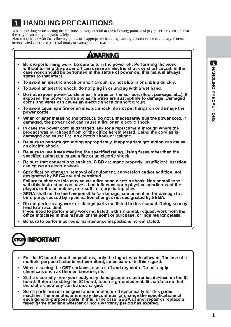
• Beforeperformingwork,besuretoturnthepoweroff.Performingtheworkwithoutturningthepoweroffcancauseanelectricshockorshortcircuit.Inthecaseworkshouldbeperformedinthestatusofpoweron,thismanualalwaysstatestothateffect.
• Toavoidanelectricshockorshortcircuit,donotpluginorunplugquickly.• Toavoidanelectricshock,donotpluginorunplugwithawethand.• Donotexposepowercordsorearthwiresonthesurface,(floor,passage,etc.).If
exposed,thepowercordsandearthwiresaresusceptibletodamage.Damagedcordsandwirescancauseanelectricshockorshortcircuit.
• Toavoidcausingafireoranelectricshock,donotputthingsonordamagethepowercords.
• Whenorafterinstallingtheproduct,donotunnecessarilypullthepowercord.Ifdamaged,thepowercordcancauseafireoranelectricshock.
• Incasethepowercordisdamaged,askforareplacementthroughwheretheproductwaspurchasedfromortheofficehereinstated.Usingthecordasisdamagedcancausefire,anelectricshockorleakage.
• Besuretoperformgroundingappropriately.Inappropriategroundingcancauseanelectricshock.
• Besuretousefusesmeetingthespecifiedrating.Usingfusesotherthanthespecifiedratingcancauseafireoranelectricshock.
• BesurethatconnectionssuchasICBDaremadeproperly.Insufficientinsertioncancauseanelectricshock.
• Specificationchanges,removalofequipment,conversionand/oraddition,notdesignatedbySEGAarenotpermitted.
-Failuretoobservethismaycauseafireoranelectricshock.Non-compliancewiththisinstructioncanhaveabadinfluenceuponphysicalconditionsoftheplayersortheonlookers,orresultininjuryduringplay.
-SEGAshallnotbeheldresponsiblefordamage,compensationfordamagetoathirdparty,causedbyspecificationchangesnotdesignatedbySEGA.
• Donotperformanyworkorchangepartsnotlistedinthismanual.Doingsomayleadtoanaccident.
Ifyouneedtoperformanyworknotlistedinthismanual,requestworkfromtheofficeindicatedinthismanualorthepointofpurchase,orinquiresfordetails.
• Besuretoperformperiodicmaintenanceinspectionshereinstated.
When installing or inspecting the machine, be very careful of the following points and pay attention to ensure that the player can enjoy the game safely.Non-compliance with the following points or inappropriate handling running counter to the cautionary matters herein stated can cause personal injury or damage to the machine.
• FortheICboardcircuitinspections,onlythelogictesterisallowed.Theuseofamultiple-purposetesterisnotpermitted,sobecarefulinthisregard.
• WhencleaningtheCRTsurfaces,useasoftanddrycloth.Donotapplychemicalssuchasthinner,benzene,etc.
• StaticelectricityfromyourbodymaydamagesomeelectronicsdevicesontheICboard.BeforehandlingtheICboard,touchagroundedmetallicsurfacesothatthestaticelectricitycanbedischarged.
• Somepartsarenotdesignedandmanufacturedspecificallyforthisgamemachine.Themanufacturersmaydiscontinue,orchangethespecificationsofsuchgeneral-purposeparts.Ifthisisthecase,SEGAcannotrepairorreplaceafailedgamemachinewhetherornotawarrantyperiodhasexpired.
2PREC
AU
TION
S REG
AR
DIN
G IN
STALLATIO
N LO
CATIO
N
2
PRECAUTIONS REGARDING INSTALLATION LOCATION2
2-1 LIMITATIONS OF USAGE
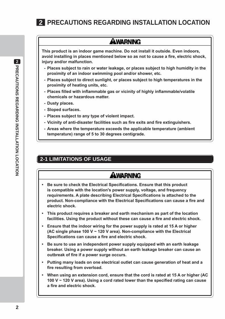
Thisproductisanindoorgamemachine.Donotinstallitoutside.Evenindoors,avoidinstallinginplacesmentionedbelowsoasnottocauseafire,electricshock,injuryand/ormalfunction.-Placessubjecttorainorwaterleakage,orplacessubjecttohighhumidityinthe
proximityofanindoorswimmingpooland/orshower,etc.-Placessubjecttodirectsunlight,orplacessubjecttohightemperaturesinthe
proximityofheatingunits,etc.-Placesfilledwithinflammablegasorvicinityofhighlyinflammable/volatile
chemicalsorhazardousmatter.-Dustyplaces.-Slopedsurfaces.-Placessubjecttoanytypeofviolentimpact.-Vicinityofanti-disasterfacilitiessuchasfireexitsandfireextinguishers.-Areaswherethetemperatureexceedstheapplicabletemperature(ambient
temperature)rangeof5to30degreescentigrade.
• BesuretochecktheElectricalSpecifications.Ensurethatthisproductiscompatiblewiththelocation'spowersupply,voltage,andfrequencyrequirements.AplatedescribingElectricalSpecificationsisattachedtotheproduct.Non-compliancewiththeElectricalSpecificationscancauseafireandelectricshock.
• Thisproductrequiresabreakerandearthmechanismaspartofthelocationfacilities.Usingtheproductwithoutthesecancauseafireandelectricshock.
• Ensurethattheindoorwiringforthepowersupplyisratedat15Aorhigher(ACsinglephase100V~120Varea).Non-compliancewiththeElectricalSpecificationscancauseafireandelectricshock.
• Besuretouseanindependentpowersupplyequippedwithanearthleakagebreaker.Usingapowersupplywithoutanearthleakagebreakercancauseanoutbreakoffireifapowersurgeoccurs.
• Puttingmanyloadsononeelectricaloutletcancausegenerationofheatandafireresultingfromoverload.
• Whenusinganextensioncord,ensurethatthecordisratedat15Aorhigher(AC100V~120Varea).Usingacordratedlowerthanthespecifiedratingcancauseafireandelectricshock.

PREC
AU
TION
S REG
AR
DIN
G PR
OD
UC
T OPER
ATION
3
3
To avoid injury and trouble, be sure to pay attention to the behavior of visitors and players.
BEFOREOPERATION
PRECAUTIONS REGARDING PRODUCT OPERATION3
Inordertoavoidaccidents,checkthefollowingbeforestartingtheoperation:
• Toensuremaximumsafetyfortheplayersandthecustomers,ensurethatwheretheproductisoperatedhassufficientlightingtoallowanywarningstoberead.Operationunderinsufficientlightingcancausebodilycontactwitheachother,hittingaccident,and/ortroublebetweencustomers.
• Besuretoperformappropriateadjustmentofthemonitor(projector).Foroperationofthismachine,donotleavemonitor'sflickeringordeviationasis.Failuretoobservethiscanhaveabadinfluenceupontheplayers'orthecustomers'physicalconditions.
• Itissuggestedtoensureaspaceallowingtheplayerswhofeelsickwhileplayingthegametotakearest.
• Checkifalloftheadjustersareincontactwiththesurface.Iftheyarenot,theCabinetcanmoveandcauseanaccident.
• Duringdailycleaning,besuretocheckthesurfaceofthesteeringwheel,gearshifter,andotherpartsthattheplayertoucheswithhishandsfordamage,cracks,orloosescrews.Ifaplayerusesthemachinewhileitisdamaged,cracked,orhasaloosescrew,theplayermaybecomeinjured.
• Duringdailycleaning,besuretochecktheseatforanyabnormality,wetness,etc.Failuretodothismayresultindeliberatetamperingornegligencebeingleftundetected.
• Toavoidinjury,besuretoprovidesufficientspacebyconsideringthepotentiallycrowdedsituationattheinstallationlocation.Insufficientinstallationspacecancausemakingbodilycontactwitheachother,hittingaccidents,and/ortroublebetweencustomers.
• Donotputanyheavyitemonthisproduct.Placinganyheavyitemontheproductcancauseafallingdownaccidentorpartsdamage.
• Donotclimbontheproduct.Climbingontheproductcancausefallingdownaccidents.Tocheckthetopportionoftheproduct,useastepladder.
• Toavoidelectricshock,checktoseeifdoor&coverpartsaredamagedoromitted.
• Toavoidelectricshock,shortcircuitand/orpartsdamage,donotputthefollowingitemsonorintheperipheryoftheproduct.Flowervases,flowerpots,cups,watertanks,cosmetics,andreceptacles/containers/vesselscontainingchemicalsandwater.
3PREC
AU
TION
S REG
AR
DIN
G PR
OD
UC
T OPER
ATION
4
DURINGOPERATION(PAYINGATTENTIONTOCUSTOMERS)
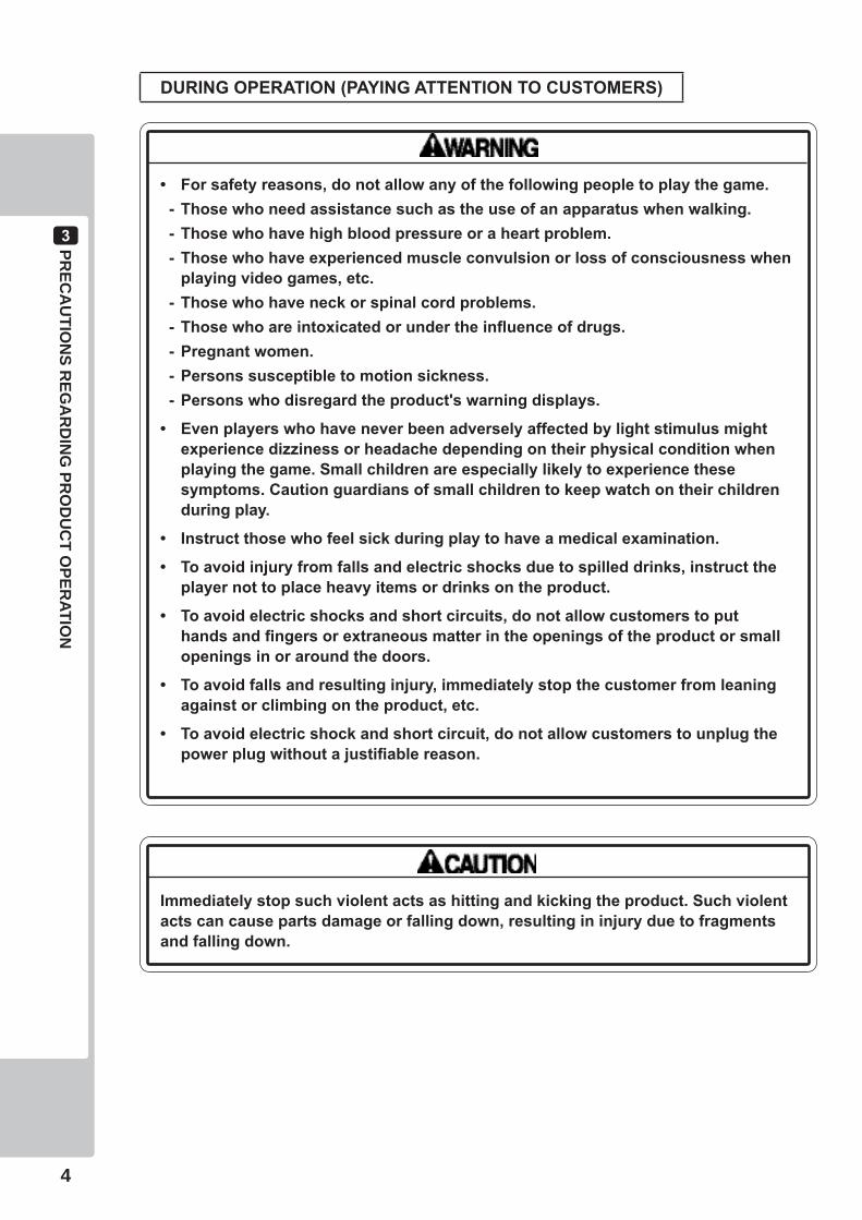
• Forsafetyreasons,donotallowanyofthefollowingpeopletoplaythegame.-Thosewhoneedassistancesuchastheuseofanapparatuswhenwalking.-Thosewhohavehighbloodpressureoraheartproblem.-Thosewhohaveexperiencedmuscleconvulsionorlossofconsciousnesswhen
playingvideogames,etc.-Thosewhohaveneckorspinalcordproblems.-Thosewhoareintoxicatedorundertheinfluenceofdrugs.-Pregnantwomen.-Personssusceptibletomotionsickness.-Personswhodisregardtheproduct'swarningdisplays.
• Evenplayerswhohaveneverbeenadverselyaffectedbylightstimulusmightexperiencedizzinessorheadachedependingontheirphysicalconditionwhenplayingthegame.Smallchildrenareespeciallylikelytoexperiencethesesymptoms.Cautionguardiansofsmallchildrentokeepwatchontheirchildrenduringplay.
• Instructthosewhofeelsickduringplaytohaveamedicalexamination.
• Toavoidinjuryfromfallsandelectricshocksduetospilleddrinks,instructtheplayernottoplaceheavyitemsordrinksontheproduct.
• Toavoidelectricshocksandshortcircuits,donotallowcustomerstoputhandsandfingersorextraneousmatterintheopeningsoftheproductorsmallopeningsinoraroundthedoors.
• Toavoidfallsandresultinginjury,immediatelystopthecustomerfromleaningagainstorclimbingontheproduct,etc.
• Toavoidelectricshockandshortcircuit,donotallowcustomerstounplugthepowerplugwithoutajustifiablereason.
Immediatelystopsuchviolentactsashittingandkickingtheproduct.Suchviolentactscancausepartsdamageorfallingdown,resultingininjuryduetofragmentsandfallingdown.
PAR
TS DESC
RIPTIO
NS
4
5
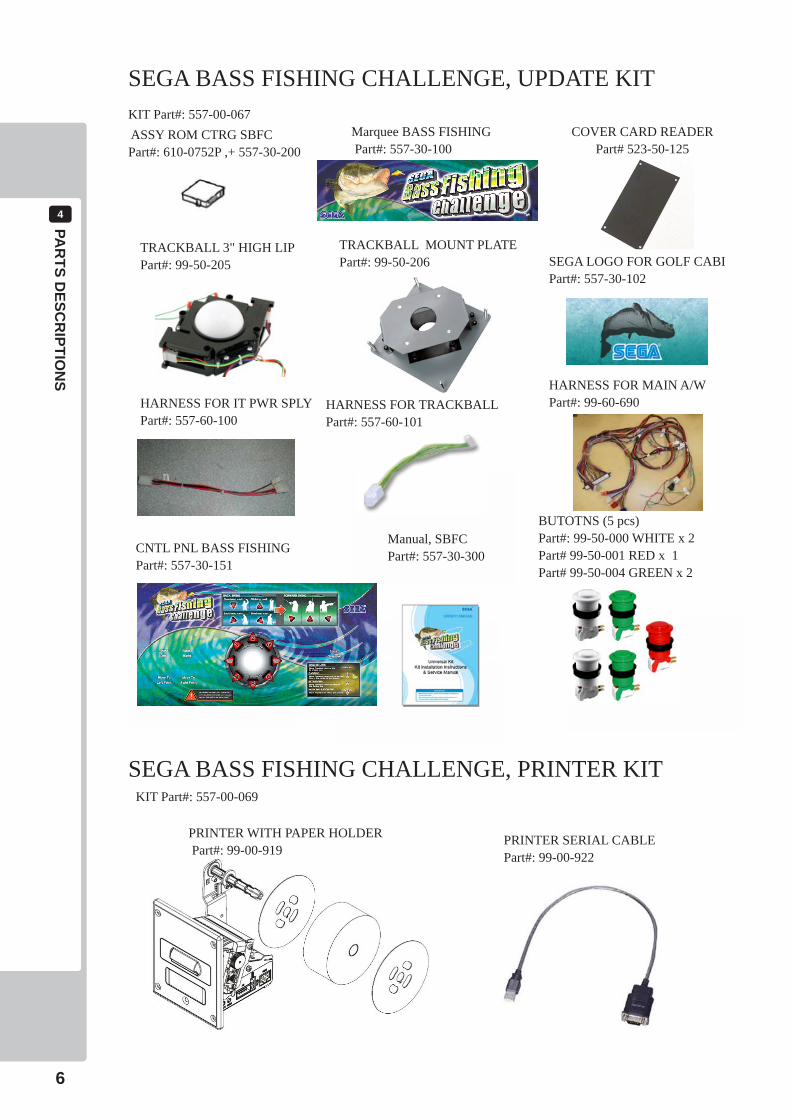
COVER CARD READERPart# 523-50-125
PART DESCRIPTIONS4
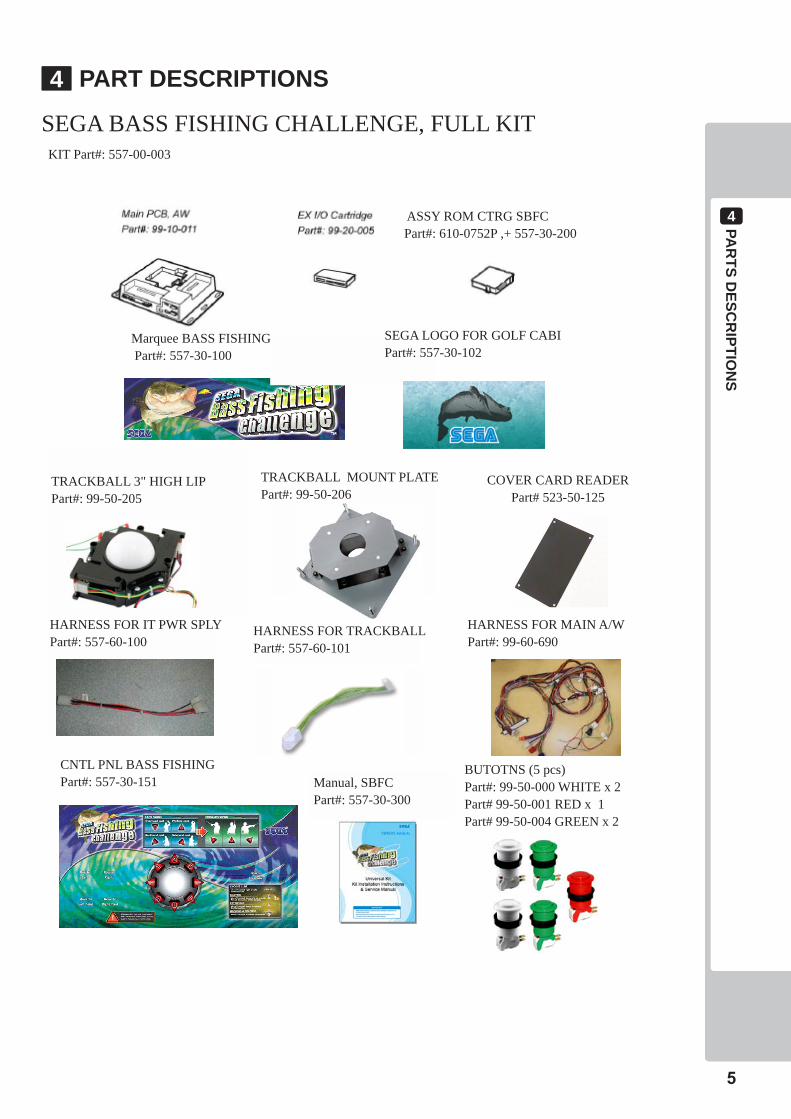
SEGA BASS FISHING CHALLENGE, FULL KITKIT Part#: 557-00-003
Marquee BASS FISHING Part#: 557-30-100
Manual, SBFCPart#: 557-30-300
HARNESS FOR TRACKBALLPart#: 557-60-101
TRACKBALL 3" HIGH LIPPart#: 99-50-205
BUTOTNS (5 pcs)Part#: 99-50-000 WHITE x 2Part# 99-50-001 RED x 1Part# 99-50-004 GREEN x 2
CNTL PNL BASS FISHINGPart#: 557-30-151
TRACKBALL MOUNT PLATEPart#: 99-50-206
SEGA LOGO FOR GOLF CABIPart#: 557-30-102
HARNESS FOR MAIN A/WPart#: 99-60-690
HARNESS FOR IT PWR SPLYPart#: 557-60-100
ASSY ROM CTRG SBFC Part#: 610-0752P ,+ 557-30-200
4
PAR
TS DESC
RIPTIO
NS
6
COVER CARD READERPart# 523-50-125
Marquee BASS FISHING Part#: 557-30-100
Manual, SBFCPart#: 557-30-300
HARNESS FOR TRACKBALLPart#: 557-60-101
TRACKBALL 3" HIGH LIPPart#: 99-50-205
BUTOTNS (5 pcs)Part#: 99-50-000 WHITE x 2Part# 99-50-001 RED x 1Part# 99-50-004 GREEN x 2
CNTL PNL BASS FISHINGPart#: 557-30-151
TRACKBALL MOUNT PLATEPart#: 99-50-206 SEGA LOGO FOR GOLF CABI
Part#: 557-30-102
HARNESS FOR MAIN A/WPart#: 99-60-690HARNESS FOR IT PWR SPLY
Part#: 557-60-100
PRINTER WITH PAPER HOLDER Part#: 99-00-919
PRINTER SERIAL CABLEPart#: 99-00-922
SEGA BASS FISHING CHALLENGE, UPDATE KITKIT Part#: 557-00-067 ASSY ROM CTRG SBFC Part#: 610-0752P ,+ 557-30-200
SEGA BASS FISHING CHALLENGE, PRINTER KITKIT Part#: 557-00-069

AC
CESSO
RIES
5
7
ACCESSORIES5Confirm that the accessories listed in the table below are present when setting up the product. Accessories marked “Spare” in the note column are consumable items but included as spares.
OWNER’S MANUAL 557-30-300 (1)This manual
6ASSEM
BLYA
NDIN
STALLATIO
N
8
ASSEMBLYANDINSTALLATION6
• Performassemblyworkbyfollowingtheprocedurehereinstated.Failuretocomplywiththeinstructionscancauseelectricshock.
• Performassemblingasperthismanual.Sincethisisacomplexmachine,incorrectassemblingcancauseanelectricshock,machinedamageand/orimproperfunctioningasperspecifiedperformance.
• Whenassembling,morethanonepersonisrequired.Dependingontheassemblywork,therearesomecasesinwhichworkingbyonepersonalonecancausepersonalinjuryorpartsdamage.
• Ensurethatconnectorsareproperlyconnected.Improperconnectionscancauseelectricshock.
• Thisworkshouldbecarriedoutbythesitemaintenancepersonnelorotherqualifiedprofessionals.Workperformedbynon-technicalpersonnelcancauseasevereaccidentsuchaselectricshock.Failingtocomplywiththisinstructioncancauseasevereaccidentsuchaselectricshocktotheplayerduringoperation.Ifnoonewithpropertechnologicalexpertiseisavailable,requestservicefromtheofficeindicatedinthisdocumentorthepointofpurchasesoastoensuresafety.
• Providesufficientspacesothatassemblingcanbeperformed.Performingworkinplaceswithnarrowspaceorlowceilingmaycauseanaccidentandassemblyworktobedifficult.
• Toperformworksafelyandavoidseriousaccidentsuchasthecabinetfallingdown,donotperformworkinplaceswherestep-likegradedifferences,aditch,orslopeexist.
• Becarefulnottodamagethewires.Damagedwiresmaycauseelectricshockorshortcircuitorpresentariskoffire.
• Donotleavepowercords,groundwires,ornetworkcablesexposedinareasofheavyfoottraffic.Doingsomaycausethemtobecomedamaged,possiblyresultinginelectricshockand/orshortcircuits.Whenlayingwiringacrossthefloor,alwaysusesafetycoverstoprotectthewires.
• Thepowercordforthisproducthasagroundterminal.Makesuretousethisgroundterminalwhenpluggingitintoanindooroutlet.Failuretoproperlygroundtheproductcouldleadtoelectrocution.Itcanalsoleadtomalfunction.
• Whenopening/closing,attaching/removingdoorsorlids,becarefulthatyourhandorfingerdoesnotgetcaughtinanything.
• Toperformtheoperationsafelyandaccuratelyyoumustuseasafe,steadyfootstoolorstepladder.Workingwithoutthismayleadtoafallandpossibleinjury.
• Wearappropriateworkclothingsothatworkcanbeperformedsafely.Useglovesandsafetyshoestopreventaccidentsorinjuries.
• Wheninstallingawireprotectioncoveroverafloor,useamaterialshapedsothatnoonepassingbywillstumbleoverit.Usingamaterialthatcouldbestumbledovermightleadtoanaccidentalfall.
• Handleplasticpartswithcare.Excessiveweightorpressuremaycausethemtobreakandthebrokenpiecesmaycauseinjury.
ASSEM
BLYA
NDIN
STALLATIO
N
6
9
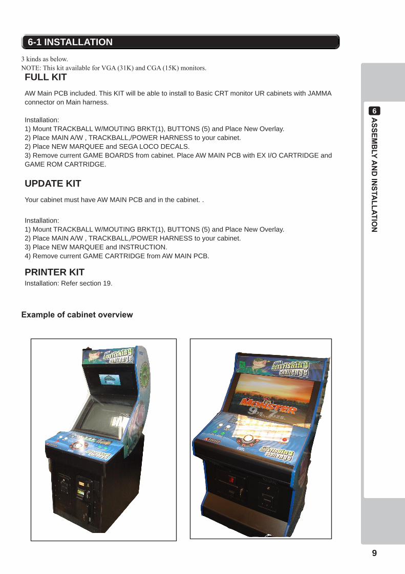
3 kinds as below. NOTE: This kit available for VGA (31K) and CGA (15K) monitors.FULL KITAW Main PCB included. This KIT will be able to install to Basic CRT monitor UR cabinets with JAMMA connector on Main harness.
Installation:1) Mount TRACKBALL W/MOUTING BRKT(1), BUTTONS (5) and Place New Overlay. 2) Place MAIN A/W , TRACKBALL,/POWER HARNESS to your cabinet.2) Place NEW MARQUEE and SEGA LOCO DECALS.3) Remove current GAME BOARDS from cabinet. Place AW MAIN PCB with EX I/O CARTRIDGE and GAME ROM CARTRIDGE.
UPDATE KITYour cabinet must have AW MAIN PCB and in the cabinet. .
Installation:1) Mount TRACKBALL W/MOUTING BRKT(1), BUTTONS (5) and Place New Overlay. 2) Place MAIN A/W , TRACKBALL,/POWER HARNESS to your cabinet.3) Place NEW MARQUEE and INSTRUCTION.4) Remove current GAME CARTRIDGE from AW MAIN PCB.
PRINTER KITInstallation: Refer section 19.
6-1 INSTALLATION
Exampleofcabinetoverview
6ASSEM
BLYA
NDIN
STALLATIO
N
10
1 Turn the main power switch on to power up.
2 The monitor will display an advertize screen.
3 The Marquee panel and push buttons will light up. (Depends of cabinet type)
4 The sound will be output from both left and right speakers on the cabinet.
6-2TURNINGONTHEPOWER
• Thefollowingexplanationassumesthattheproducthasbeenassembledproperlyasexplainedabove.Ifthereisanerrororiftheproductoperatesinamannerotherthanasindicatedbelow,cutoffthepowersupplyimmediately.Failuretodosomayresultinafireorelectricalshock.
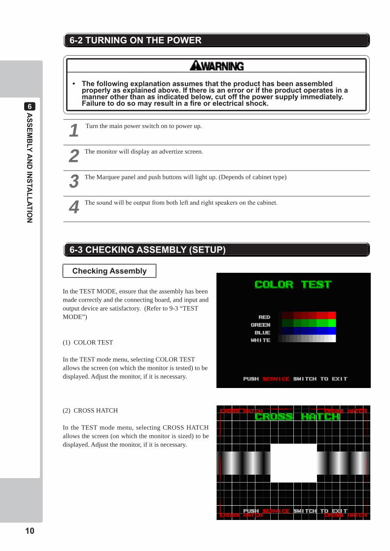
CheckingAssembly
In the TEST MODE, ensure that the assembly has been made correctly and the connecting board, and input and output device are satisfactory. (Refer to 9-3 “TEST MODE”)
(1) COLOR TEST
In the TEST mode menu, selecting COLOR TEST allows the screen (on which the monitor is tested) to be displayed. Adjust the monitor, if it is necessary.
(2) CROSS HATCH
In the TEST mode menu, selecting CROSS HATCH allows the screen (on which the monitor is sized) to be displayed. Adjust the monitor, if it is necessary.
6-3CHECKINGASSEMBLY(SETUP)
ASSEM
BLYA
NDIN
STALLATIO
N
6
11
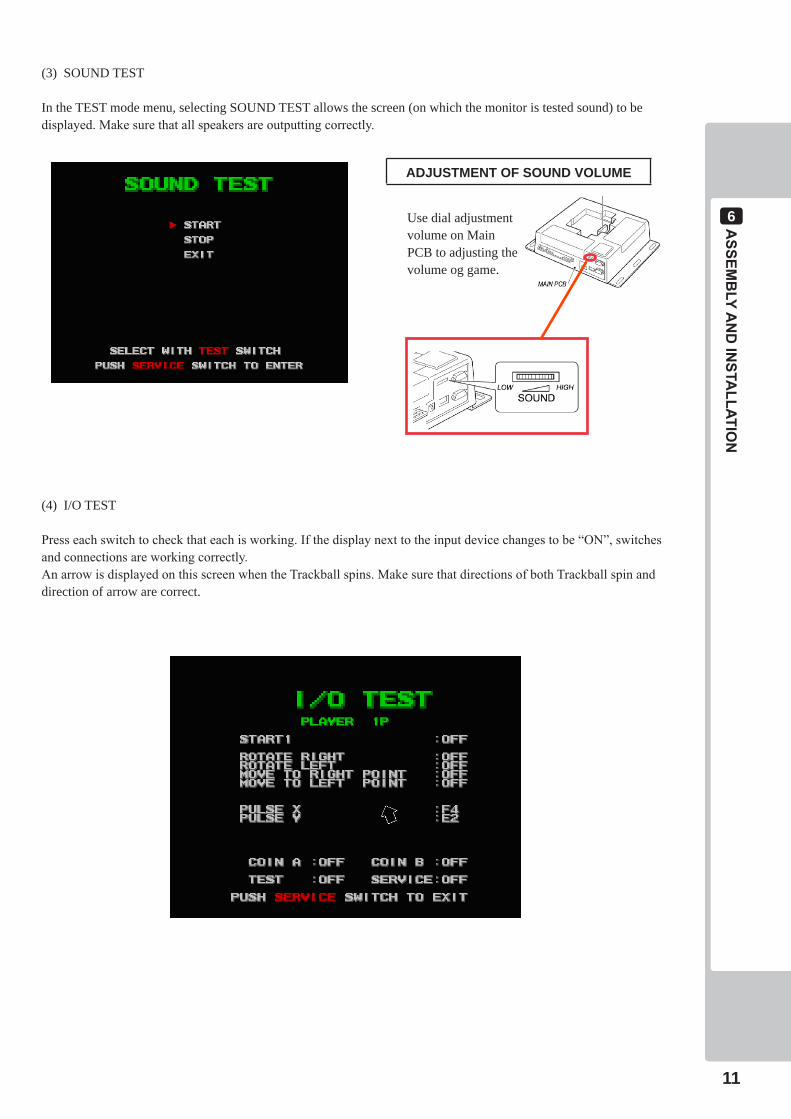
(3) SOUND TEST
In the TEST mode menu, selecting SOUND TEST allows the screen (on which the monitor is tested sound) to be displayed. Make sure that all speakers are outputting correctly.
(4) I/O TEST
Press each switch to check that each is working. If the display next to the input device changes to be “ON”, switches and connections are working correctly.An arrow is displayed on this screen when the Trackball spins. Make sure that directions of both Trackball spin and direction of arrow are correct.
ADJUSTMENT OF SOUND VOLUME
Use dial adjustment volume on Main PCB to adjusting the volume og game.

6ASSEM
BLYA
NDIN
STALLATIO
N
12
(5) CLOCK SETTINGS
Enter in “SYSTEM MENU”, “CONFIGURATION” and “CLOCK SETTING” and enter date correctly.Select CLOCK SETTINGS to display setting date and hour of Main PCB screen.Use the TEST Button to move the cursor and the SERVICE Button to change the set value.
YEAR: Set a year ; from 2002 to 2038.MONTH: Set a month; from 1 to 12.DAY: Set a day; from 1 to 31.HOUR: Set time; from 0 to 23.MINUTE: Set minutes; from 0 to 59.
Move the cursor to “SAVE&EXIT” after setting change is complete. Press SERVICE Button to return to SYSTEM menu after setting is saved.
(6) PRINTER TESTIf connecting a printer, enter in “SYSTEM MENU”, “CONFIGURATION”, “GAME SETTINGS”,” PRINTER SETTINGS” and ” PRINTER TEST”. Test printing.
The following result is printed form a printer.
PREC
AUTIO
NSW
HEN
MOVIN
GTH
EMACHINE
7
13
PRECAUTIONSWHENMOVINGTHEMACHINE87
• Whenmoving themachine, be sure to pull out the plug from the power supply.Moving themachinewiththeplugstillinsertedcancausethepowercordtobedamaged,resultinginafireand/or electric shock.
•Whenmovingthemachineonthefloor,retracttheadjusters,andensurethatthecastersmakecontactwiththefloor.Paycarefulattentionsothatthecastersdonotrunoverpowercordsandearthwires.Damagingthepowercordscancauseanelectricshockand/orshortcircuit.
•Whenmovingthecabinet,donotpushitfromtheside.Pushitfromtheback.Pushingthecabinetfromthesidecanhavethecabinetfalldown,causingpersonalinjury,etc.Incasethefloorhasslantedsurfacesorstep-likedifferences,besuretomovethemachineby2ormorepersons.•Whendetachedalwayskeepthecabinetonalevelsurfaceandmakesureitdoesnotstarttolean to theleftorrightwhilstworkingonit.
Donotpushonanypartsmadeofglassorplastic,asthesepartsmaybreakandresultinbodilyinjury.
Whenmovingthecabinetdonotholdorpushtheonitorpanel.Thiscoulddeformtheirshapeorcausedamagetothem.
Pushingthecabinetfromthesidemaymakeitfallover.Alwayspushitfromtheback.
8GA
ME D
ESCR
IPTION
14
- Join a tournament in 4 lakes. A player joins bass fishing tournaments in 4 days. Tournaments are hold in each lake (California Delta, Lake Champlain, Lake Tohopekaliga, Lake Havasu) in all over the US and a player choose a lake.
- Contest gross bass weight in 4 days. Content gross 5 basses weight per day in a tournament and final ranking is decided by gross bass weight in all 4 days. (“Weigh-in” is hold after finishing each day and tentative ranking is decided. A big weigh-in is hold in special site after finishing 4 days and the victory is decided.).
- Keeping maximum 5 basses per day are possible. A player can keep maximum 5 basses in a livewell. At the fishing of 6th basses, release the lightest bass in the 6 fishes automatically. The bass which body length is less than 12inch is NON-KEEPR and a player can’t count in livewell. It is released automatically.
- Gross weight ranking in each lake. The player will join weigh in ranking that is contest of gross bass weight in selected lake. After finishing the game, the ranking is reflected the ranking list in advertise screen.
- Bass world-record ranking. This ranking is to contest only one bass weight in each lake. If one bass weight is heavy, it is possible to enter in the ranking. After finishing the game, the world-record ranking is reflected the ranking list in advertise screen.
- Fish a largemouth bass and smallmouth bass. A player can fish Largemouth bass and Smallmouth bass in this game. The kinds of basses caught in each lake are as follow; Largemouth Bass: California Delta, Lake Tohopekaliga, Lake Havasu Smallmouth Bass : Lake Champlain
- Number of Players. 1-4 players are playable.
- Game Mode There are 2 modes in this game; “Short Competition” mode is to join a tournament in only one day. “Full Competition” mode is to join a tournament in 4 days. If a player selects “Continue” in Short Competition, a player can join a tournament in all 4 days.
8-1 GAME OUT LINE
GAME DESCRIPTION8The following explanations apply to the product when functioning properly. If the product operates differently from the following contents, a fault may have occurred. Immediately look into and eliminate the cause of the fault to ensure proper operation.
Demo movies and game rankings are displayed on a monitor during power distribution.Audio may also be played from speakers on the video cabinet and gun controller.It is possible to select whether sound is output or not during Advertise mode through System menu.
GA
ME D
ESCR
IPTION
8
15
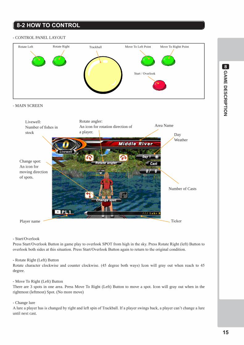
- CONTROL PANEL LAYOUT
8-2HOWTOCONTROL
- MAIN SCREEN
Rotate angler:An icon for rotation direction of a player.
Area NameLivewell:Number of fishes in stock Day
Weather
Number of Casts
Move To Left Point Move To Rightt PointRotate Left Rotate Right
Start / Overlook
Trackball
Player name
Change spot:An icon for moving direction of spots.
Ticker
- Start/OverlookPress Start/Overlook Button in game play to overlook SPOT from high in the sky. Press Rotate Right (left) Button to overlook both sides at this situation. Press Start/Overlook Button again to return to the original condition.
- Rotate Right (Left) ButtonRotate character clockwise and counter clockwise. (45 degree both ways) Icon will gray out when reach to 45 degree.
- Move To Right (Left) ButtonThere are 3 spots in one area. Press Move To Right (Left) Button to move a spot. Icon will gray out when in the rightmost (leftmost) Spot. (No more move)
- Change lureA lure a player has is changed by right and left spin of Trackball. If a player swings back, a player can’t change a lure until next cast.
8GA
ME D
ESCR
IPTION
16
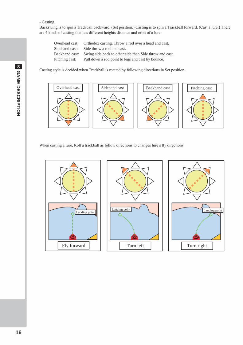
- CastingBackswing is to spin a Trackball backward. (Set position.) Casting is to spin a Trackball forward. (Cast a lure.) There are 4 kinds of casting that has different heights distance and orbit of a lure.
Overhead cast: Orthodox casting. Throw a rod over a head and cast. Sidehand cast: Side throw a rod and cast. Backhand cast: Swing side back to other side then Side throw and cast. Pitching cast: Pull down a rod point to legs and cast by bounce.
Casting style is decided when Trackball is rotated by following directions in Set position.
Overhead cast Sidehand cast Backhand cast Pitching cast
Fly forward
Landing point
Turn left
Landing point
Turn right
Landing point
When casting a lure, Roll a trackball as follow directions to changes lure’s fly directions.
GA
ME D
ESCR
IPTION
8
17
8-3HOWTOFISH
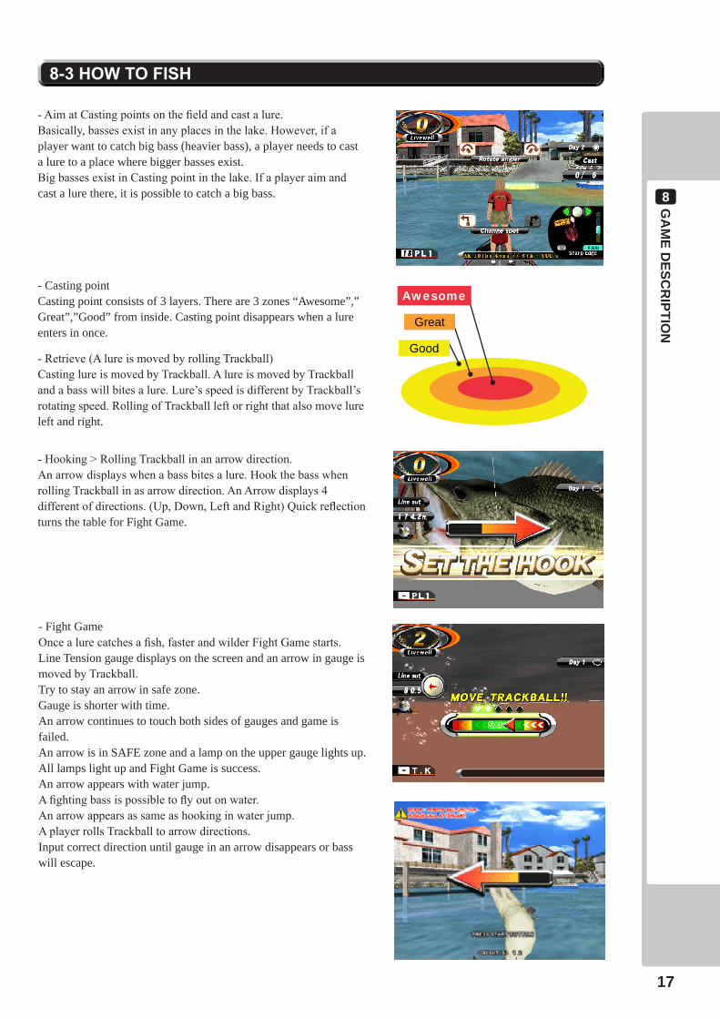
- Aim at Casting points on the field and cast a lure. Basically, basses exist in any places in the lake. However, if a player want to catch big bass (heavier bass), a player needs to cast a lure to a place where bigger basses exist. Big basses exist in Casting point in the lake. If a player aim and cast a lure there, it is possible to catch a big bass.
Awesome
Great
Good
- Casting pointCasting point consists of 3 layers. There are 3 zones “Awesome”,”Great”,”Good” from inside. Casting point disappears when a lure enters in once.
- Retrieve (A lure is moved by rolling Trackball)Casting lure is moved by Trackball. A lure is moved by Trackball and a bass will bites a lure. Lure’s speed is different by Trackball’s rotating speed. Rolling of Trackball left or right that also move lure left and right.
- Hooking > Rolling Trackball in an arrow direction.An arrow displays when a bass bites a lure. Hook the bass when rolling Trackball in as arrow direction. An Arrow displays 4 different of directions. (Up, Down, Left and Right) Quick reflection turns the table for Fight Game.
- Fight GameOnce a lure catches a fish, faster and wilder Fight Game starts.Line Tension gauge displays on the screen and an arrow in gauge is moved by Trackball. Try to stay an arrow in safe zone.Gauge is shorter with time. An arrow continues to touch both sides of gauges and game is failed.An arrow is in SAFE zone and a lamp on the upper gauge lights up.All lamps light up and Fight Game is success.An arrow appears with water jump.A fighting bass is possible to fly out on water.An arrow appears as same as hooking in water jump.A player rolls Trackball to arrow directions.Input correct direction until gauge in an arrow disappears or bass will escape.
8GA
ME D
ESCR
IPTION
18
8-4BONUSGAME
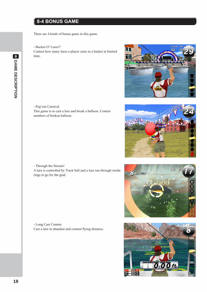
There are 4 kinds of bonus game in this game.
- Bucket O’ Lures!!Contest how many lures a player casts in a basket in limited time.
- Pop’em CarnivalThis game is to cast a lure and break a balloon. Contest numbers of broken balloon.
- Through the Stream!A lure is controlled by Track ball and a lure run through inside rings to go for the goal.
- Long Cast ContestCast a lure in abandon and content flying distance.
GA
ME D
ESCR
IPTION
8
19
8-5SPECIALLURE
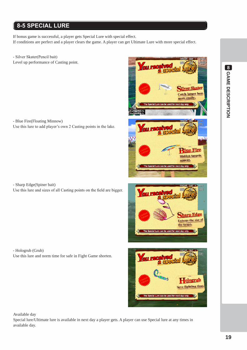
If bonus game is successful, a player gets Special Lure with special effect.If conditions are perfect and a player clears the game. A player can get Ultimate Lure with more special effect.
- Silver Skater(Pencil bait)Level up performance of Casting point.
- Blue Fire(Floating Minnow)Use this lure to add player’s own 2 Casting points in the lake.
- Sharp Edge(Spiner bait)Use this lure and sizes of all Casting points on the field are bigger.
- Hologrub (Grub)Use this lure and norm time for safe in Fight Game shorten.
Available daySpecial lure/Ultimate lure is available in next day a player gets. A player can use Special lure at any times in available day.
8GA
ME D
ESCR
IPTION
20
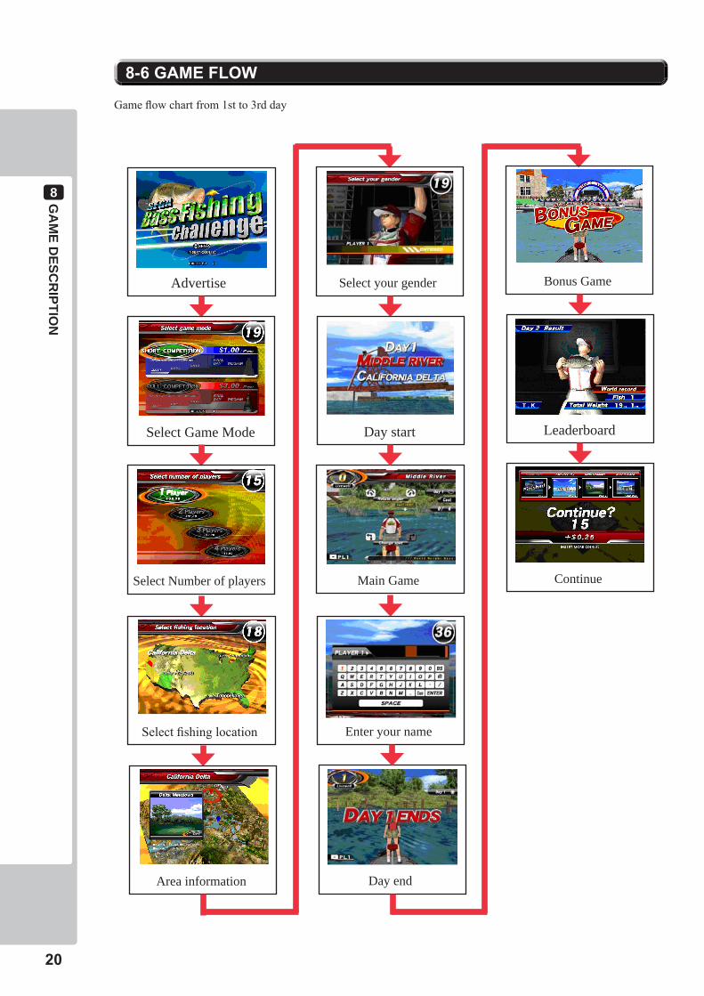
8-6GAMEFLOW
Game flow chart from 1st to 3rd day
Advertise
Select Game Mode
Select Number of players
Select fishing location
Area information
Select your gender
Day start
Main Game
Enter your name
Day end
Bonus Game
Leaderboard
Continue

GA
ME D
ESCR
IPTION
8
21
Game flow chart for 4th day
Weigh-in
Leaderboard
Weigh-in
Tournament recap
Result
Big Bass award
Continue
Game over
9SYSTEMMEN
U
22
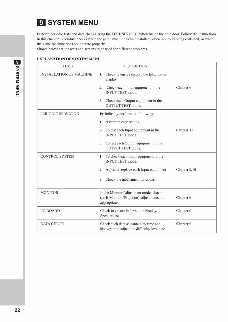
Perform periodic tests and data checks using the TEST/SERVICE button inside the coin door. Follow the instructions in this chapter to conduct checks when the game machine is first installed, when money is being collected, or when the game machine does not operate properly.Shown below are the tests and screens to be used for different problems.
EXPLANATION OF SYSTEM MENU
ITEMS DESCRIPTION
INSTALLATION OF MACHINE 1. Check to ensure display the Information display.
2. Check each Input equipment in the INPUT TEST mode.
Chapter 6
3. Check each Output equipment in the OUTPUT TEST mode.
PERIODIC SERVICING Periodically perform the following:
1. Ascertain each setting.
2. To test each Input equipment in the INPUT TEST mode.
Chapter 12
3. To test each Output equipment in the OUTPUT TEST mode.
CONTROL SYSTEM 1. To check each Input equipment in the INPUT TEST mode.
2.
3.
Adjust or replace each Input equipment
Check the mechanical functions
Chapter 9,16
MONITOR In the Monitor Adjustment mode, check to see if Monitor (Projector) adjustments are appropriate.
Chapter 6
I/O BOARD Check to encure Information display.Speaker test
Chapter 9
DATA CHECK Check such data as game play time and histogram to adjust the difficulty level, etc.
Chapter 9
SYSTEMMENU9
SYSTEMMEN
U
9
23
• WhenyouentertheTestMode,fractionalcoinandbonusadderdataiserased.
• Adjustthesoundtotheoptimumvolume,takingintoconsiderationtheenvironmentalrequirementsoftheinstallationlocation.
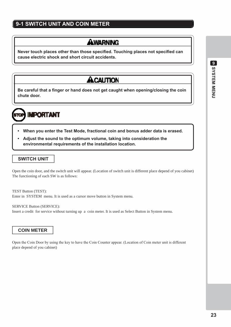
9-1SWITCHUNITANDCOINMETER
Becarefulthatafingerorhanddoesnotgetcaughtwhenopening/closingthecoinchutedoor.
Nevertouchplacesotherthanthosespecified.Touchingplacesnotspecifiedcancauseelectricshockandshortcircuitaccidents.
SWITCHUNIT
Open the coin door, and the switch unit will appear. (Location of switch unit is different place depend of you cabinet)The functioning of each SW is as follows:
TEST Button (TEST): Enter in SYSTEM menu. It is used as a cursor move button in System menu.
SERVICE Button (SERVICE): Insert a credit for service without turning up a coin meter. It is used as Select Button in System menu.
COIN METER
Open the Coin Door by using the key to have the Coin Counter appear. (Location of Coin meter unit is different place depend of you cabinet)
9SYSTEMMEN
U
24
• Whenchangingthegameconfiguration,changeswillnottakeeffectuntiltheGameTestModeproperlyafterconfigurationchanges.BesuretoexittheGameTestModeproperlyafterconfigurationchanges.
• Donotconfigurethegameinwaysnotdescribedinthistext.Itispossiblethatthegamewillnotfunctionproperly.
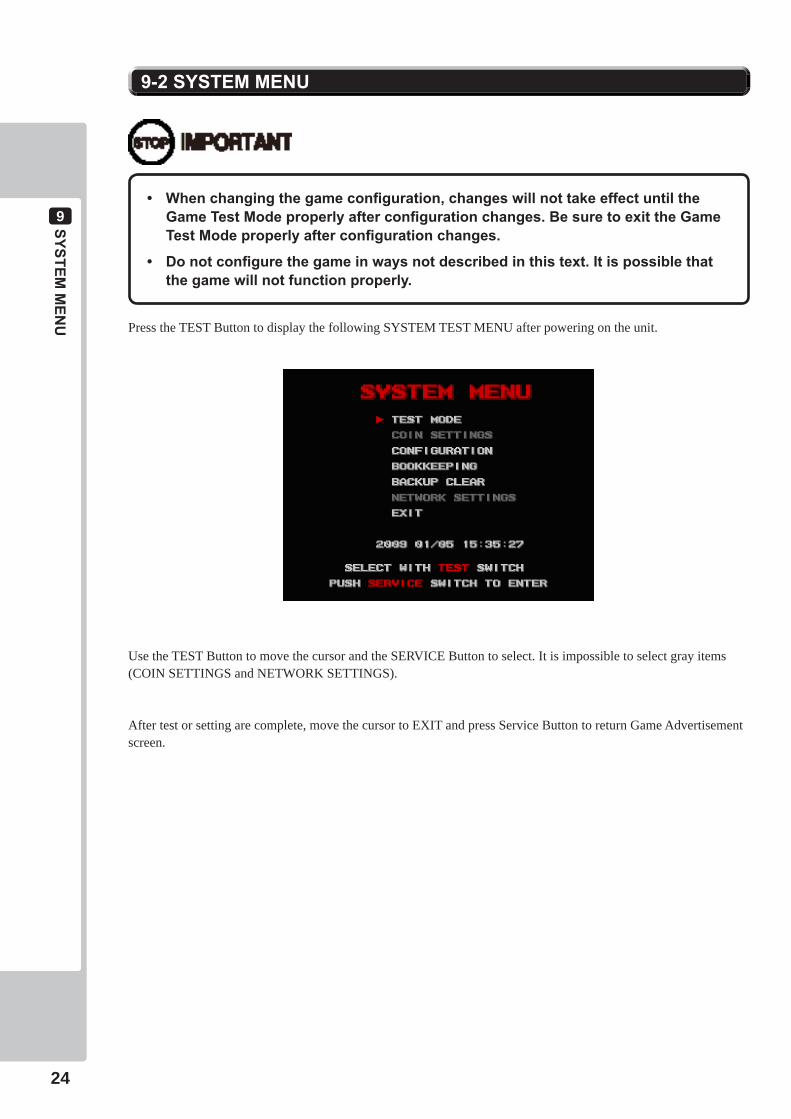
9-2SYSTEMMENU
Press the TEST Button to display the following SYSTEM TEST MENU after powering on the unit.
Use the TEST Button to move the cursor and the SERVICE Button to select. It is impossible to select gray items (COIN SETTINGS and NETWORK SETTINGS).
After test or setting are complete, move the cursor to EXIT and press Service Button to return Game Advertisement screen.

SYSTEMMEN
U
9
25
9-3TESTMODE
9-3-1 TEST MODE MENU
Select GAME TEST MODE in System Menu screen to display Game Test Menu.
1) Press the TEST Button to move the cursor.
2) Move the cursor to the desired test item, and press the Service Button to return each test screen.
3) Move the cursor to EXIT after test is complete and press the TEST Button to return to System Menu.
9-3-2 COLOR TEST
Select COLOR TEST to display monitor color test.
Press the Service Button to return the TEST MODE menu after test is complete.
9-3-3 CROSS HATCH
Select CROSS HATCH to display monitor display size test.
Press the Service Button to return the TEST MODE menu after test is complete.

9SYSTEMMEN
U
26
9-3-4 SOUND TEST
Select SOUND TEST to display the monaural sound test screen, when setting “MONO” in AUDIO MODE of SYSTEM SETTINGS.
1) Select “START” to output sound.
2) Select “STOP” to stop sound.
3) Select “EXIT” to return to TEST MODE screen after test is complete,.
Select SOUND TEST to display stereo sound test screen, when setting “STEREO” in “AUDIO MODE” of SYSTEM SETTINGS of CONFIGURATION..
1) Select “RIGHT” to output sound from right speaker.
2) Select “LEFT” to output sound from left speaker.
3) Select “CENTER” to output sound from both left & right speakers.
4) Select “STOP” to stop sound.
5) Select “EXIT” to go back to TEST MODE screen after test is complete.
9-3-5 MEMORY TEST
Select MEMORY TEST to display Main PCB RAM test.
1) Press the TEST Button to start to R/W RAM test. This test can’t be canceled until it is finished.
2) Press the Service Button to return the TEST MODE menu screen after test is complete.
SYSTEMMEN
U
9
27
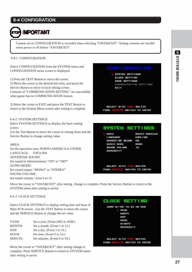
9-4 CONFIGRATION
Content set in CONFIGURATION is recorded when selecting “SAVE&EXIT”. Setting contents are invalid when power is off before “SAVE&EXIT”.
9-4-1 CONFIGURATION
Select CONFIGURATION from the SYSTEM menu and CONFIGURATION menu screen is displayed.
1) Press the TEST Button to move the cursor.2) Move the cursor to the desired test item, and press the Service Button to move to each setting screen. Contents of “COMMUNICATION SETTING” are unavailable when game has no COMMUNICATION feature.
3) Move the cursor to EXIT and press the TEST Button to return to the System Menu screen after setting is complete.
9-4-2 SYSTEM SETTINGSSelect SYSTEM SETTINGS to display the basic setting screen. Use the Test Button to move the cursor to setting items and the Service Button to change setting value.
AREA: Set the operation area; NORTH AMERICA or OTHER.LANGUAGE: ENGLISHADVERTISE SOUND:Set sound in Advertisement; “ON” or “OFF”AUDIO MODE:Set sound output; “MONO” or “STEREO”SOUND VOLUME:Set sound volume.; from 0 to 15
9-4-3 CLOCK SETTINGS
Select CLOCK SETTINGS to display setting date and hour of Main PCB screen. Use the TEST Button to move the cursor and the SERVICE Button to change the set value.
YEAR: Set a year. (From 2002 to 2038.)MONTH: Set a month. (From 1 to 12.)DAY: Set a day. (From 1 to 31.)HOUR: Set time. (From 0 to 23.)MINUTE: Set minutes. (From 0 to 59.)
Move the cursor to “SAVE&EXIT” after setting change is complete. Press SERVICE Button to return to SYSTEM menu after setting is saved.
Move the cursor to “SAVE&EXIT” after setting change is complete. Press the Service Button to return to the SYSTEM menu after setting is saved.
9SYSTEMMEN
U
28
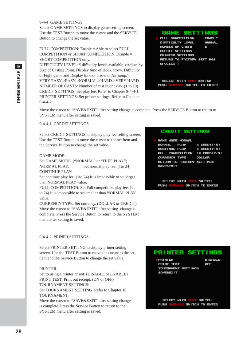
9-4-4 GAME SETTINGSSelect GAME SETTINGS to display game setting screen.Use the TEST Button to move the cursor and the SERVICE Button to change the set value.
FULL COMPETITION: Enable = Able to select FULL COMPETITION or SHORT COMPETITION. Disable = SHORT COMPETITION only.DIFFICULTY LEVEL: 5 difficulty levels available. (Adjust by Size of Casting Point, Display time of Hook arrow, Difficulty of Fight game and Display time of arrow in Air jump.)VERY EASY->EASY->NORMAL->HARD->VERY HARDNUMBER OF CASTS: Number of cast in one day. (1 to 10)CREDIT SETTINGS: Set play fee. Refer to Chapter 9-4-4-1.PRINTER SETTINGS: Set printer settings. Refer to Chapter 9-4-4-2
Move the cursor to “SAVE&EXIT” after setting change is complete. Press the SERVICE Button to return to SYSTEM menu after setting is saved.
9-4-4-1 CREDIT SETTINGS
Select CREDIT SETTINGS to display play fee setting screen. Use the TEST Button to move the cursor to the set item and the Service Button to change the set value.
GAME MODE: Set GAME MODE. (“NORMAL” or “FREE PLAY”)NORMAL PLAY: Set normal play fee. (1to 24)CONTINUE PLAY:Set continue play fee. (1to 24) It is impossible to set larger than NORMAL PLAY value.FULL COMPETITION: Set Full competition play fee. (1 to 24) It is impossible to set smaller than NORMAL PLAY value.CURRENCY TYPE: Set currency. (DOLLAR or CREDIT)Move the cursor to “SAVE&EXIT” after setting change is complete. Press the Service Button to return to the SYSTEM menu after setting is saved.
9-4-4-2 PRINER SETTINGS
Select PRINTER SETTING to display printer setting screen. Use the TEST Button to move the cursor to the set item and the Service Button to change the set value.
PRINTER: Set to using a printer or not. (DISABLE or ENABLE)PRINT TEST: Print out receipt. (ON or OFF)TOURNAMENT SETTINGS:Set TOURNAMENT SETTING. Refer to Chapter 10 TOURNAMENT.Move the cursor to “SAVE&EXIT” after setting change is complete. Press the Service Button to return to the SYSTEM menu after setting is saved.
SYSTEMMEN
U
9
29
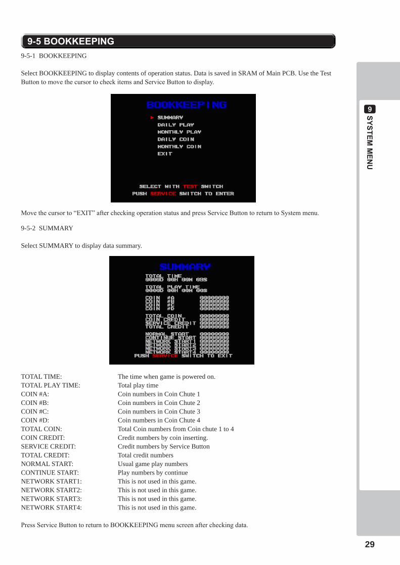
9-5BOOKKEEPING9-5-1 BOOKKEEPING
Select BOOKKEEPING to display contents of operation status. Data is saved in SRAM of Main PCB. Use the Test Button to move the cursor to check items and Service Button to display.
Move the cursor to “EXIT” after checking operation status and press Service Button to return to System menu.
9-5-2 SUMMARY
Select SUMMARY to display data summary.
TOTAL TIME: The time when game is powered on.TOTAL PLAY TIME: Total play timeCOIN #A: Coin numbers in Coin Chute 1COIN #B: Coin numbers in Coin Chute 2COIN #C: Coin numbers in Coin Chute 3COIN #D: Coin numbers in Coin Chute 4TOTAL COIN: Total Coin numbers from Coin chute 1 to 4COIN CREDIT: Credit numbers by coin inserting.SERVICE CREDIT: Credit numbers by Service ButtonTOTAL CREDIT: Total credit numbersNORMAL START: Usual game play numbersCONTINUE START: Play numbers by continueNETWORK START1: This is not used in this game.NETWORK START2: This is not used in this game.NETWORK START3: This is not used in this game.NETWORK START4: This is not used in this game.
Press Service Button to return to BOOKKEEPING menu screen after checking data.

9SYSTEMMEN
U
30
9-5-3 DAILY PLAY
Select DAILY PLAY to display daily play checking screen. Daily play number, continue number, average play time display.
After checking, press Service Button to display next page. Return to BOOKKEEPING menu when last page displayed.
9-5-4 MONTHLY PLAY
Select MONTHLY PLAY to display monthly play checking screen. Monthly play number; continue number and average play time display.
After checking, press the Service Button to display next page. Return to BOOKKEEPING menu screen when last page displayed.
9-5-5 DAILY COIN DATA
Select DAILY COIN DATA to display daily coin insert checking screen. Daily coin insert number of coin chute 1 to 4 and credit number by Service Button display.
After checking, press the Service Button to display next page. Return to BOOKKEEPING menu screen when last page displayed.
9-5-6 MONTHLY COIN DATA
Select MONTHLY COIN DATA to display monthly coin insert checking screen. Monthly coin insert number of coin chute 1to 4 and credit number by Service Button display.
After checking, press Service Button to display next page. Return to BOOKKEEPING menu when last page displayed.
SYSTEMMEN
U
9
31
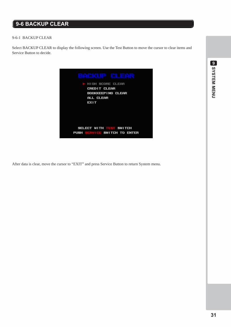
9-6-1 BACKUP CLEAR
Select BACKUP CLEAR to display the following screen. Use the Test Button to move the cursor to clear items and Service Button to decide.
After data is clear, move the cursor to “EXIT” and press Service Button to return System menu.
9-6BACKUPCLEAR
9SYSTEMMEN
U
32
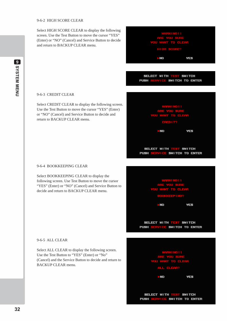
9-6-2 HIGH SCORE CLEAR
Select HIGH SCORE CLEAR to display the following screen. Use the Test Button to move the cursor “YES” (Enter) or “NO” (Cancel) and Service Button to decide and return to BACKUP CLEAR menu.
9-6-3 CREDIT CLEAR
Select CREDIT CLEAR to display the following screen. Use the Test Button to move the cursor “YES” (Enter) or “NO” (Cancel) and Service Button to decide and return to BACKUP CLEAR menu.
9-6-4 BOOKKEEPING CLEAR
Select BOOKKEEPING CLEAR to display the following screen. Use Test Button to move the cursor “YES” (Enter) or “NO” (Cancel) and Service Button to decide and return to BACKUP CLEAR menu.
9-6-5 ALL CLEAR
Select ALL CLEAR to display the following screen. Use the Test Button to “YES” (Enter) or “No” (Cancel) and the Service Button to decide and return to BACKUP CLEAR menu.
10
33
TOU
RN
AM
ENT
TOURNAMENT10
10-1TOURNAMENT
• OpeningtimeofTournamentisbasedonChapter9-4-3,CLOCKSETTING,soinputcorrecttimeinCLOCKSETTINGS.
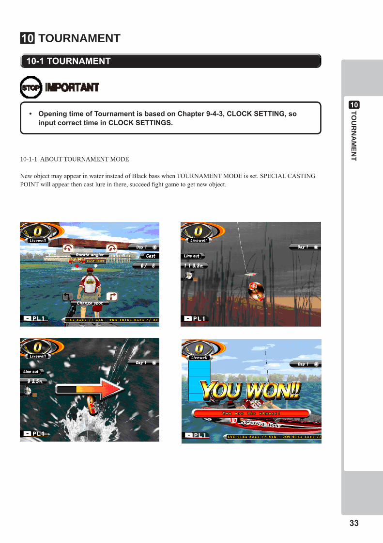
10-1-1 ABOUT TOURNAMENT MODE
New object may appear in water instead of Black bass when TOURNAMENT MODE is set. SPECIAL CASTING POINT will appear then cast lure in there, succeed fight game to get new object.
10
34
TOU
RN
AM
ENT
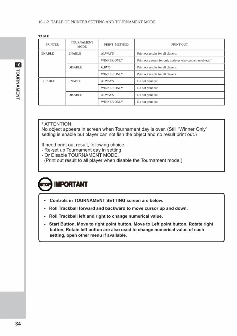
10-1-2 TABLE OF PRINTER SETTING AND TOURNAMENT MODE
TABLE
PRINTER TOURNAMENT MODE PRINT METHOD PRINT OUT
ENABLE ENABLE ALWAYS Print out results for all players.
WINNER ONLY Print out a result for only a player who catches an object.*
DISABLE ALWAYS Print out results for all players.
WINNER ONLY Print out results for all players.
DISABLE ENABLE ALWAYS Do not print out.
WINNER ONLY Do not print out.
DISABLE ALWAYS Do not print out.
WINNER ONLY Do not print out.
• ControlsinTOURNAMENTSETTINGscreenarebelow.
-RollTrackballforwardandbackwardtomovecursorupanddown.
-RollTrackballleftandrighttochangenumericalvalue.
-StartButton,Movetorightpointbutton,MovetoLeftpointbutton,Rotaterightbutton,Rotateleftbuttonarealsousedtochangenumericalvalueofeachsetting,openothermenuifavailable.
* ATTENTION: NoobjectappearsinscreenwhenTournamentdayisover.(Still“WinnerOnly”settingisenablebutplayercannotfishtheobjectandnoresultprintout.)
Ifneedprintoutresult,followingchoice.-Re-setupTournamentdayinsetting.-OrDisableTOURNAMENTMODE.(PrintoutresulttoallplayerwhendisabletheTournamentmode.)
10
35
TOU
RN
AM
ENT
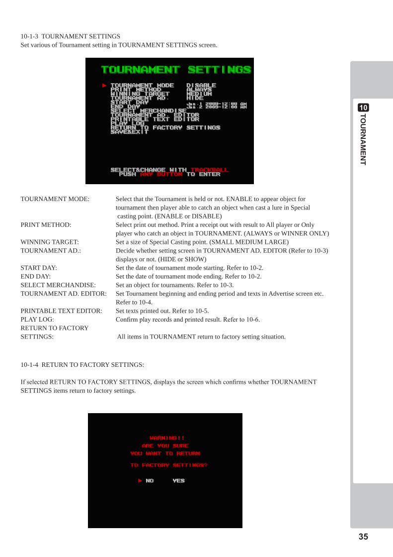
10-1-3 TOURNAMENT SETTINGSSet various of Tournament setting in TOURNAMENT SETTINGS screen.
TOURNAMENT MODE: Select that the Tournament is held or not. ENABLE to appear object for tournament then player able to catch an object when cast a lure in Special casting point. (ENABLE or DISABLE)PRINT METHOD: Select print out method. Print a receipt out with result to All player or Only player who catch an object in TOURNAMENT. (ALWAYS or WINNER ONLY)WINNING TARGET: Set a size of Special Casting point. (SMALL MEDIUM LARGE)TOURNAMENT AD.: Decide whether setting screen in TOURNAMENT AD. EDITOR (Refer to 10-3) displays or not. (HIDE or SHOW)START DAY: Set the date of tournament mode starting. Refer to 10-2.END DAY: Set the date of tournament mode ending. Refer to 10-2.SELECT MERCHANDISE: Set an object for tournaments. Refer to 10-3.TOURNAMENT AD. EDITOR: Set Tournament beginning and ending period and texts in Advertise screen etc. Refer to 10-4.PRINTABLE TEXT EDITOR: Set texts printed out. Refer to 10-5.PLAY LOG: Confirm play records and printed result. Refer to 10-6.RETURN TO FACTORYSETTINGS: All items in TOURNAMENT return to factory setting situation.
10-1-4 RETURN TO FACTORY SETTINGS:
If selected RETURN TO FACTORY SETTINGS, displays the screen which confirms whether TOURNAMENT SETTINGS items return to factory settings.
10
36
TOU
RN
AM
ENT
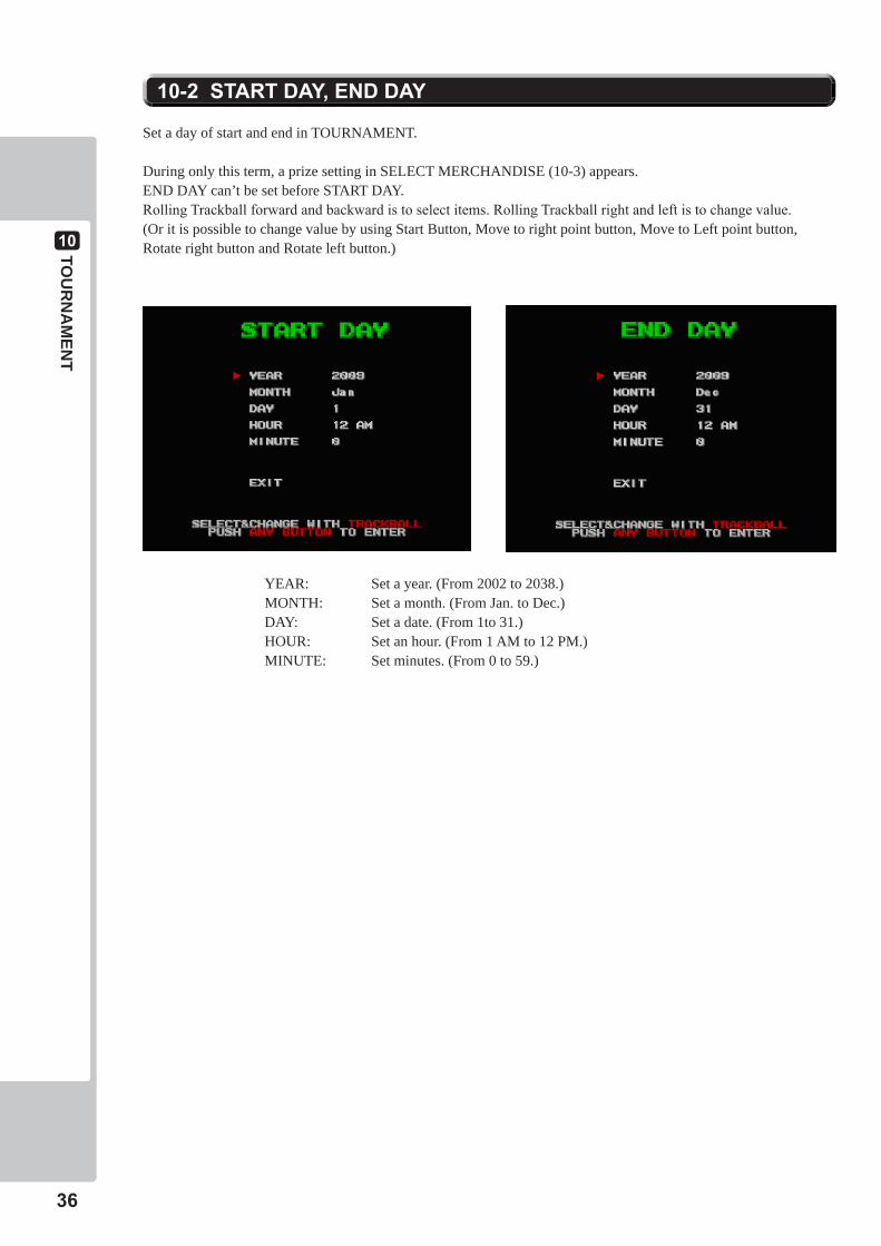
10-2STARTDAY,ENDDAY
Set a day of start and end in TOURNAMENT.
During only this term, a prize setting in SELECT MERCHANDISE (10-3) appears. END DAY can’t be set before START DAY. Rolling Trackball forward and backward is to select items. Rolling Trackball right and left is to change value.(Or it is possible to change value by using Start Button, Move to right point button, Move to Left point button, Rotate right button and Rotate left button.)
YEAR: Set a year. (From 2002 to 2038.)MONTH: Set a month. (From Jan. to Dec.)DAY: Set a date. (From 1to 31.)HOUR: Set an hour. (From 1 AM to 12 PM.)MINUTE: Set minutes. (From 0 to 59.)
10
37
TOU
RN
AM
ENT
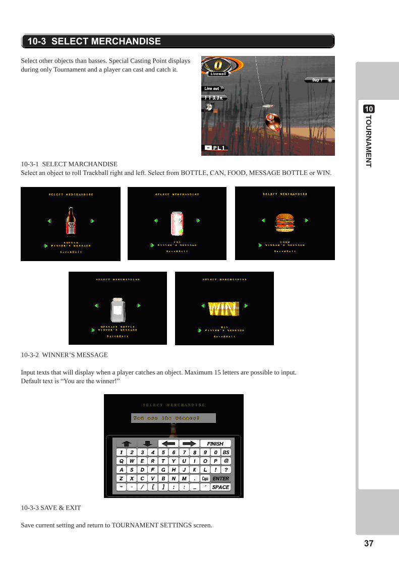
10-3SELECTMERCHANDISE
10-3-1 SELECT MARCHANDISESelect an object to roll Trackball right and left. Select from BOTTLE, CAN, FOOD, MESSAGE BOTTLE or WIN.
Select other objects than basses. Special Casting Point displays during only Tournament and a player can cast and catch it.
10-3-2 WINNER’S MESSAGE
Input texts that will display when a player catches an object. Maximum 15 letters are possible to input.Default text is “You are the winner!”
10-3-3 SAVE & EXIT
Save current setting and return to TOURNAMENT SETTINGS screen.
10
38
TOU
RN
AM
ENT
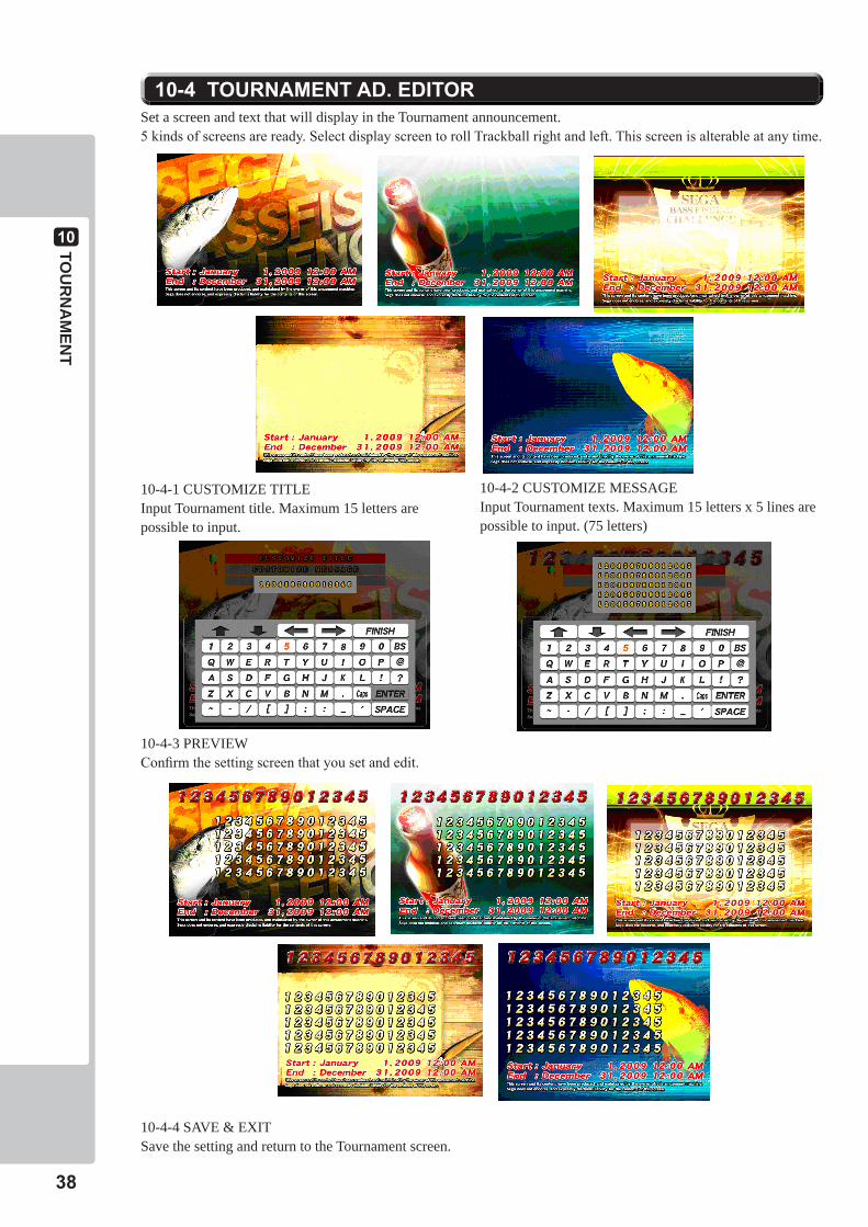
10-4TOURNAMENTAD.EDITOR
10-4-1 CUSTOMIZE TITLEInput Tournament title. Maximum 15 letters are possible to input.
10-4-2 CUSTOMIZE MESSAGEInput Tournament texts. Maximum 15 letters x 5 lines are possible to input. (75 letters)
Set a screen and text that will display in the Tournament announcement. 5 kinds of screens are ready. Select display screen to roll Trackball right and left. This screen is alterable at any time.
10-4-3 PREVIEWConfirm the setting screen that you set and edit.
10-4-4 SAVE & EXITSave the setting and return to the Tournament screen.
10
39
TOU
RN
AM
ENT
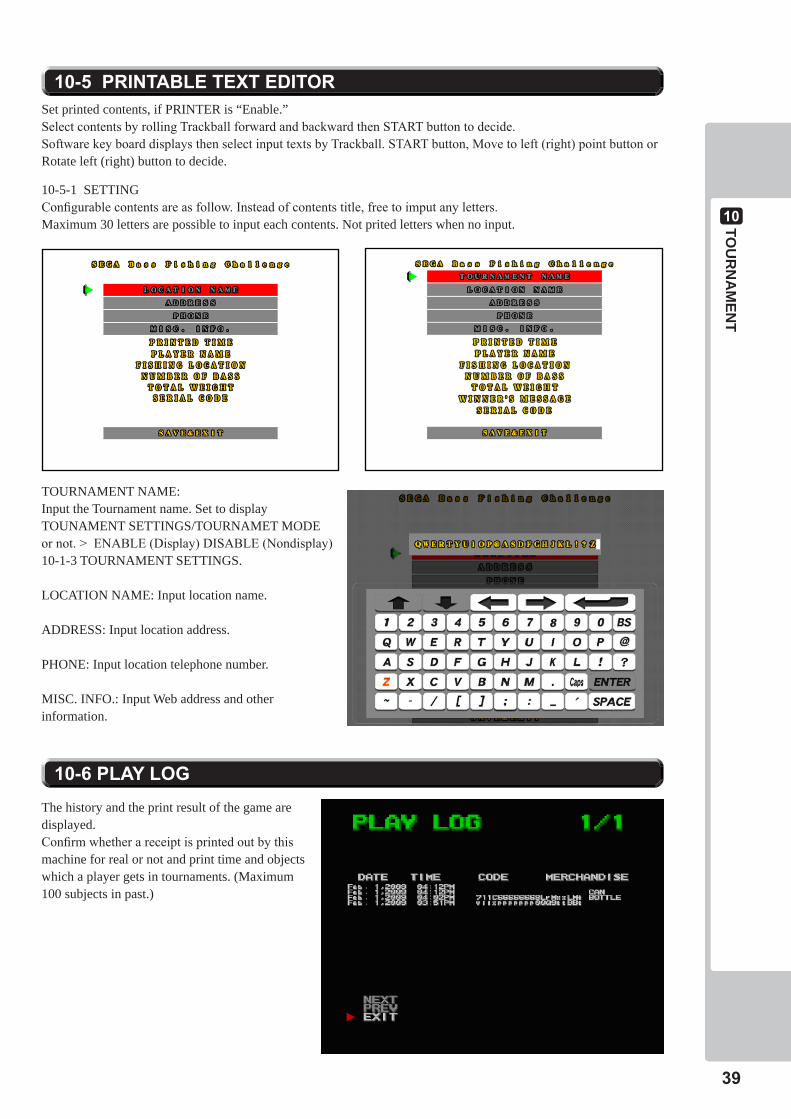
10-5PRINTABLETEXTEDITOR
10-5-1 SETTINGConfigurable contents are as follow. Instead of contents title, free to imput any letters.Maximum 30 letters are possible to input each contents. Not prited letters when no input.
Set printed contents, if PRINTER is “Enable.”Select contents by rolling Trackball forward and backward then START button to decide.Software key board displays then select input texts by Trackball. START button, Move to left (right) point button or Rotate left (right) button to decide.
TOURNAMENT NAME: Input the Tournament name. Set to display TOUNAMENT SETTINGS/TOURNAMET MODE or not. > ENABLE (Display) DISABLE (Nondisplay)10-1-3 TOURNAMENT SETTINGS.
LOCATION NAME: Input location name.
ADDRESS: Input location address.
PHONE: Input location telephone number.
MISC. INFO.: Input Web address and other information.
10-6PLAYLOGThe history and the print result of the game are displayed. Confirm whether a receipt is printed out by this machine for real or not and print time and objects which a player gets in tournaments. (Maximum 100 subjects in past.)

10
40
TOU
RN
AM
ENT
10-7ABOUTPRINTER
10-7-1 PRINT OUT
10-7-2 USUAL PRINT RESULT
Game logo
Text that edit at Printable Text Editor. (Refer Chapter 10-5 PRINTABLE TEXT)
Time of print out.Player’s nameName of Lake
QTY of FishWeight
Attention
Serial code
10
41
TOU
RN
AM
ENT
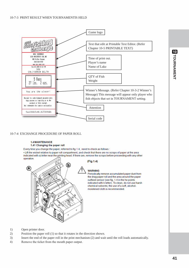
10-7-3 PRINT RESULT WHEN TOURNAMENTIS HELD
Game logo
Text that edit at Printable Text Editor. (Refer Chapter 10-5 PRINTABLE TEXT)
Time of print out.Player’s nameName of Lake
QTY of FishWeight
Attention
Serial code
Winner’s Message. (Refer Chapter 10-3-2 Winner’s Message) This message will appear only player who fish objects that set in TOURNAMENT setting.
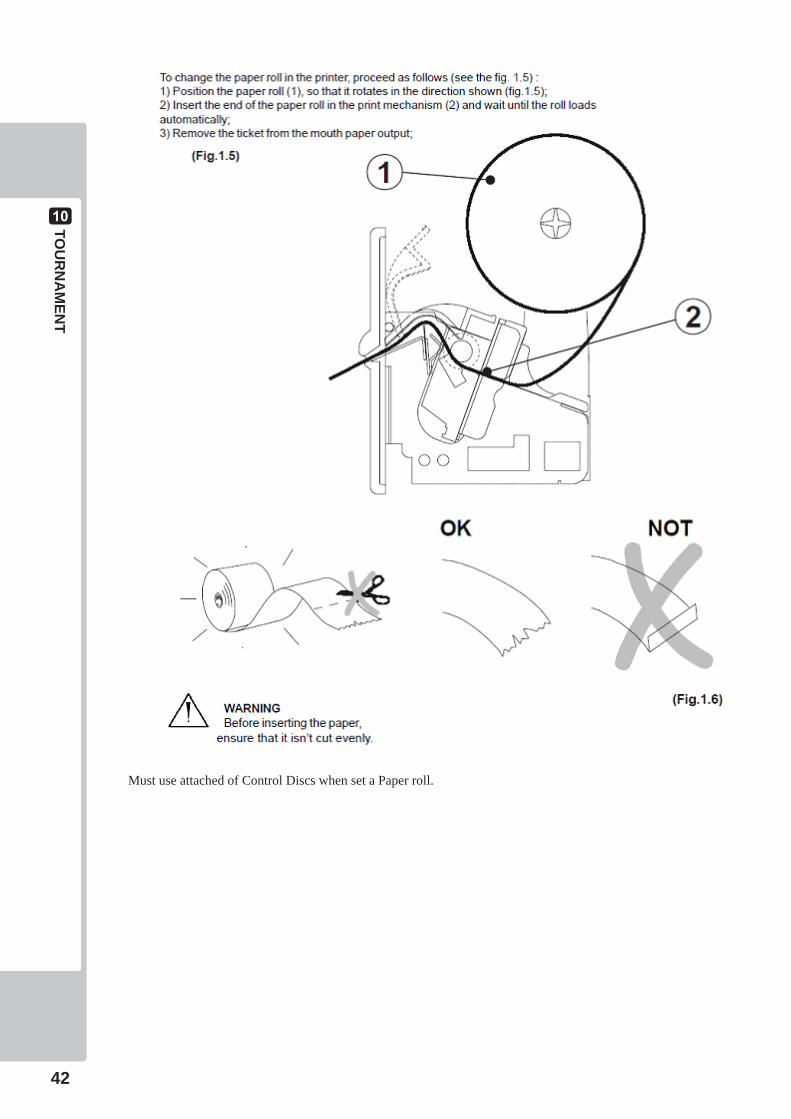
10-7-4 EXCHANGE PROCEDURE OF PAPER ROLL
1) Open printer door.2) Position the paper roll (1) so that it rotates in the direction shown.3) Insert the end of the paper roll in the print mechanism (2) and wait until the roll loads automatically.4) Remove the ticket from the mouth paper output.
10
42
TOU
RN
AM
ENT
Must use attached of Control Discs when set a Paper roll.
10
43
TOU
RN
AM
ENT
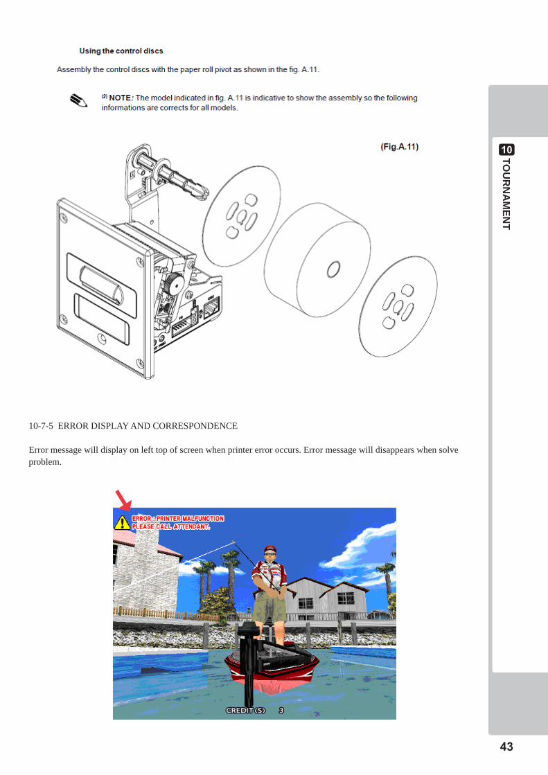
10-7-5 ERROR DISPLAY AND CORRESPONDENCE
Error message will display on left top of screen when printer error occurs. Error message will disappears when solve problem.
10
44
TOU
RN
AM
ENT
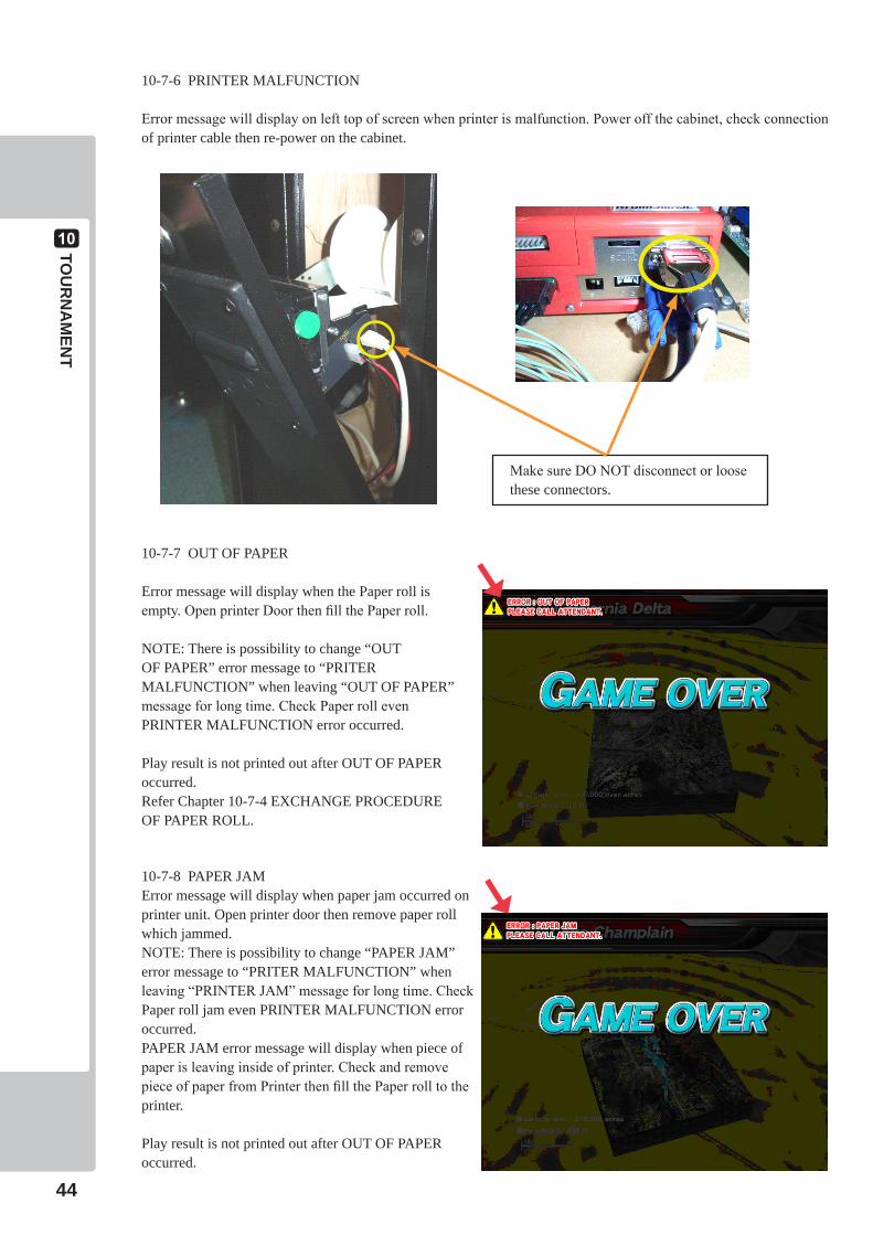
10-7-6 PRINTER MALFUNCTION
Error message will display on left top of screen when printer is malfunction. Power off the cabinet, check connection of printer cable then re-power on the cabinet.
Make sure DO NOT disconnect or loose these connectors.
10-7-7 OUT OF PAPER
Error message will display when the Paper roll is empty. Open printer Door then fill the Paper roll.
NOTE: There is possibility to change “OUT OF PAPER” error message to “PRITER MALFUNCTION” when leaving “OUT OF PAPER” message for long time. Check Paper roll even PRINTER MALFUNCTION error occurred.
Play result is not printed out after OUT OF PAPER occurred.Refer Chapter 10-7-4 EXCHANGE PROCEDURE OF PAPER ROLL.
10-7-8 PAPER JAMError message will display when paper jam occurred on printer unit. Open printer door then remove paper roll which jammed.NOTE: There is possibility to change “PAPER JAM” error message to “PRITER MALFUNCTION” when leaving “PRINTER JAM” message for long time. Check Paper roll jam even PRINTER MALFUNCTION error occurred. PAPER JAM error message will display when piece of paper is leaving inside of printer. Check and remove piece of paper from Printer then fill the Paper roll to the printer.
Play result is not printed out after OUT OF PAPER occurred.

11
45
PERIO
DIC
INSPEC
TION
PERIODIC INSPECTION
• Onceayear,checktoseeifpowercordsaredamaged,theplugissecurelyinserted,dustisaccumulatedbetweenthesocketoutletandthepowerplug,etc.Usingtheproductwithaccumulateddustintheinteriormaycausefireorelectricshock.
• Neveruseawaterjet,etc.tocleantheinsideandoutsideofthecabinet.Ifwetnessoccursforanyreason,donotusetheproductuntilithascompletelydried.
• Onceayear,requesttheofficeshownonthismanualorthedealerfromwhomtheproductwasoriginallypurchasedtoperformtheinternalcleaning.Usingtheproductwithaccumulateddustintheinteriormaycausefireorotheraccidents.
Notethatyouareliableforthecostofcleaningtheinteriorparts.
• Thereisthedangerofaccidentsinvolvingelectricalshortscircuitsorfirecausedby factors such as the deterioration of insulation in electrical and electronicequipmentovertime.Checkthattherearenoabnormalitiessuchasodorsfromburning.
The items listed below require periodic check and maintenance to retain the performance of this machine
and to ensure safe business operation.
When handling the controller, the player will be in direct contact with it. In order to always allow the player
to enjoy the game, be sure to clean it regularly. Also, it is advisable to provide wet tissue, etc. available for
player use.
CleaningtheCabinetSurfaces
When the cabinet surfaces are badly soiled, remove stains with a soft cloth dipped in water or diluted (with water) chemical detergent and squeezed dry. To avoid damaging surface finish, do not use such solvents as thinner, benzine, etc. other than ethyl alcohol, or abrasives, bleaching agent and chemical dustcloth.Some general-purpose household, kitchen and furniture cleaning products may contain strong solvents that degrade plastic components, coatings, and print. Before using any cleaning product, read the product's cautionary notes carefully and test the product first on a small area that is not highly visible.
11
12TROUBLESH
OOTIN
G
46
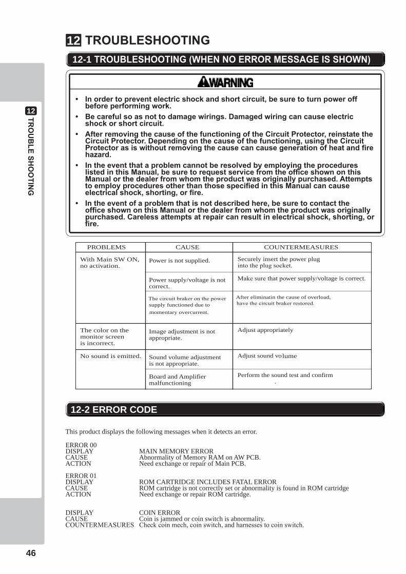
TROUBLESHOOTING1212-1 TROUBLESHOOTING(WHENNOERRORMESSAGEISSHOWN)
• Inordertopreventelectricshockandshortcircuit,besuretoturnpoweroffbeforeperformingwork.
• Becarefulsoasnottodamagewirings.Damagedwiringcancauseelectricshockorshortcircuit.
• AfterremovingthecauseofthefunctioningoftheCircuitProtector,reinstatetheCircuitProtector.Dependingonthecauseofthefunctioning,usingtheCircuitProtectorasiswithoutremovingthecausecancausegenerationofheatandfirehazard.
• IntheeventthataproblemcannotberesolvedbyemployingtheprocedureslistedinthisManual,besuretorequestservicefromtheofficeshownonthisManualorthedealerfromwhomtheproductwasoriginallypurchased.AttemptstoemployproceduresotherthanthosespecifiedinthisManualcancauseelectricalshock,shorting,orfire.
• Intheeventofaproblemthatisnotdescribedhere,besuretocontacttheofficeshownonthisManualorthedealerfromwhomtheproductwasoriginallypurchased.Carelessattemptsatrepaircanresultinelectricalshock,shorting,orfire.
PROBLEMS CAUSE COUNTERMEASURES
Power is not supplied.
Power supply/voltage is not correct.
Image adjustment is not appropriate.
Sound volume adjustment is not appropriate.
Board and Amplifier malfunctioning
With Main SW ON, no activation.
The color on the
is incorrect.
No sound is emitted.
Securely insert the power plug into the plug socket.
Make sure that power supply/voltage is correct.
Adjust appropriately
Adjust sound vo
Perform the sound test and confirm.
monitor screen
lume
The circuit braker on the powersupply functioned due to momentary overcurrent.
After eliminatin the cause of overload, have the circuit braker restored.
12-2 ERROR CODE
This product displays the following messages when it detects an error.
ERROR 00DISPLAY MAIN MEMORY ERRORCAUSE Abnormality of Memory RAM on AW PCB.ACTION Need exchange or repair of Main PCB.
ERROR 01DISPLAY ROM CARTRIDGE INCLUDES FATAL ERRORCAUSE ROM cartridge is not correctly set or abnormality is found in ROM cartridgeACTION Need exchange or repair ROM cartridge.
DISPLAY COIN ERRORCAUSE Coin is jammed or coin switch is abnormality.COUNTERMEASURES Check coin mech, coin switch, and harnesses to coin switch.
GAMEB
D
13
47
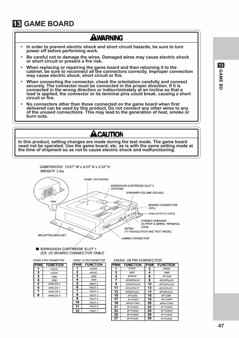
GAMEBOARD13
Inthisproduct,settingchangesaremadeduringthetestmode.Thegameboardneednotbeoperated.Usethegameboard,etc.asiswiththesamesettingmadeatthetimeofshipmentsoasnottocauseelectricshockandmalfunctioning.
• Inordertopreventelectricshockandshortcircuithazards,besuretoturnpoweroffbeforeperformingwork.
• Becarefulnottodamagethewires.Damagedwiresmaycauseelectricshockorshortcircuitorpresentafirerisk.
• Whenreplacingorrepairingthegameboardandthenreturningittothecabinet,besuretoreconnectalltheconnectorscorrectly.Improperconnectionmaycauseelectricshock,shortcircuitorfire.
• Whenconnectingtheconnector,checktheorientationcarefullyandconnectsecurely.Theconnectormustbeconnectedintheproperdirection.Ifitisconnectedinthewrongdirectionorindiscriminatelyataninclinesothataloadisapplied,theconnectororitsterminalpinscouldbreak,causingashortcircuitorfire.
• Noconnectorsotherthanthoseconnectedonthegameboardwhenfirstdeliveredcanbeusedbythisproduct.Donotconnectanyotherwirestoanyoftheunusedconnections.Thismayleadtothegenerationofheat,smokeorburnouts.
13GAMEB
D
48
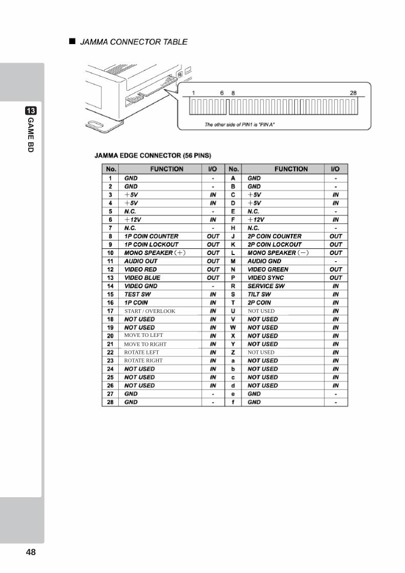
NOT USEDSTART / OVERLOOK
NOT USED
MOVE TO LEFT
ROTATE LEFTMOVE TO RIGHT
ROTATE RIGHT
GAMEB
D
13
49

13GAMEB
D
50
CABINETPA
RTSD
ESCRIPTIO
N
14
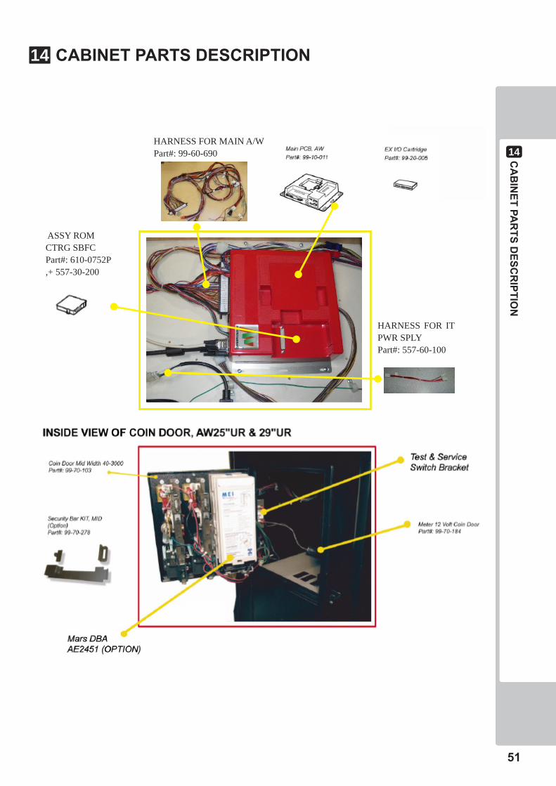
51
ASSY ROM CTRG SBFC Part#: 610-0752P ,+ 557-30-200
HARNESS FOR MAIN A/WPart#: 99-60-690
HARNESS FOR IT PWR SPLYPart#: 557-60-100
CABINETPARTSDESCRIPTION14
15PARTSLIST,C
ONTR
OLLER
52
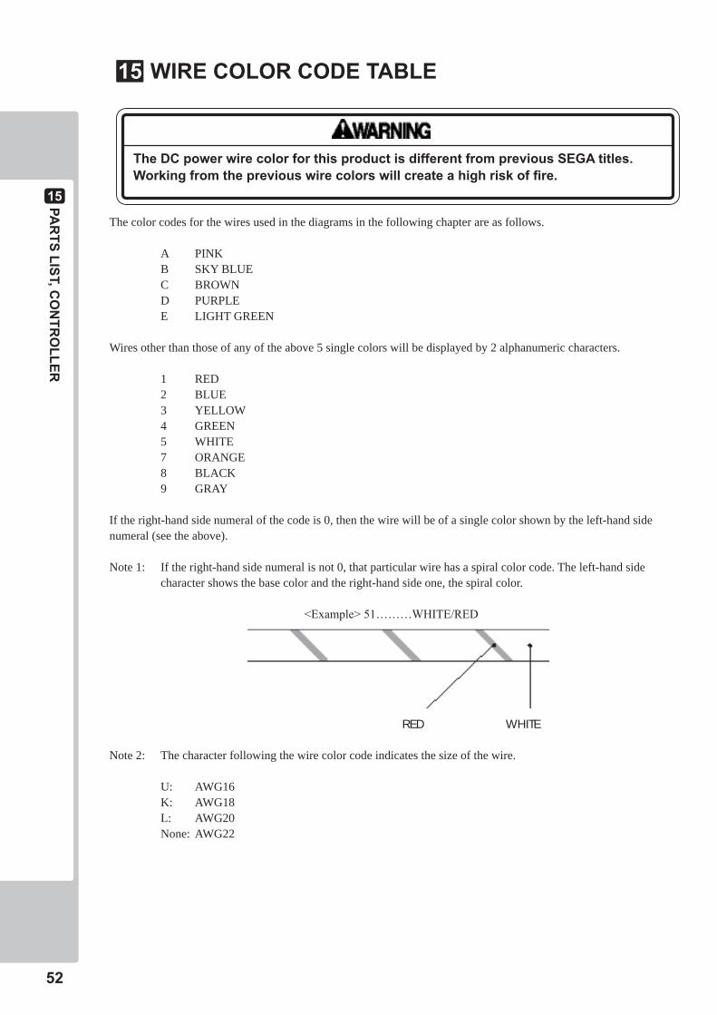
The color codes for the wires used in the diagrams in the following chapter are as follows.
A PINK B SKY BLUE C BROWN D PURPLE E LIGHT GREEN
Wires other than those of any of the above 5 single colors will be displayed by 2 alphanumeric characters.
1 RED 2 BLUE 3 YELLOW 4 GREEN 5 WHITE 7 ORANGE 8 BLACK 9 GRAY
If the right-hand side numeral of the code is 0, then the wire will be of a single color shown by the left-hand side numeral (see the above).
Note 1: If the right-hand side numeral is not 0, that particular wire has a spiral color code. The left-hand side character shows the base color and the right-hand side one, the spiral color.
<Example> 51………WHITE/RED
RED WHITE
Note 2: The character following the wire color code indicates the size of the wire.
U: AWG16 K: AWG18 L: AWG20 None: AWG22
TheDCpowerwirecolorforthisproductisdifferentfrompreviousSEGAtitles.Workingfromthepreviouswirecolorswillcreateahighriskoffire.
15 WIRECOLORCODETABLE15
WIREC
OLO
RCODETA
BLE
16
53
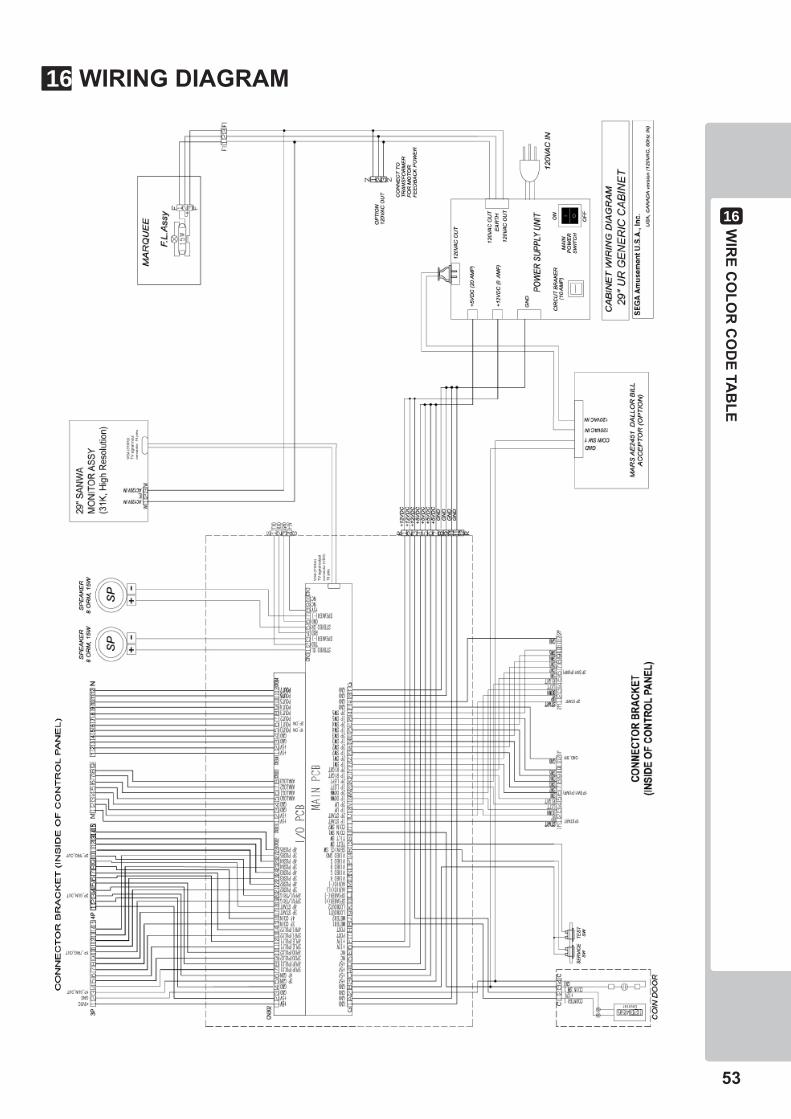
161676WIRINGDIAGRAM
54
The Font to be used in the game.The typefaces included herein are solely developed by DynaComware.
LICENSE MARK1617
55
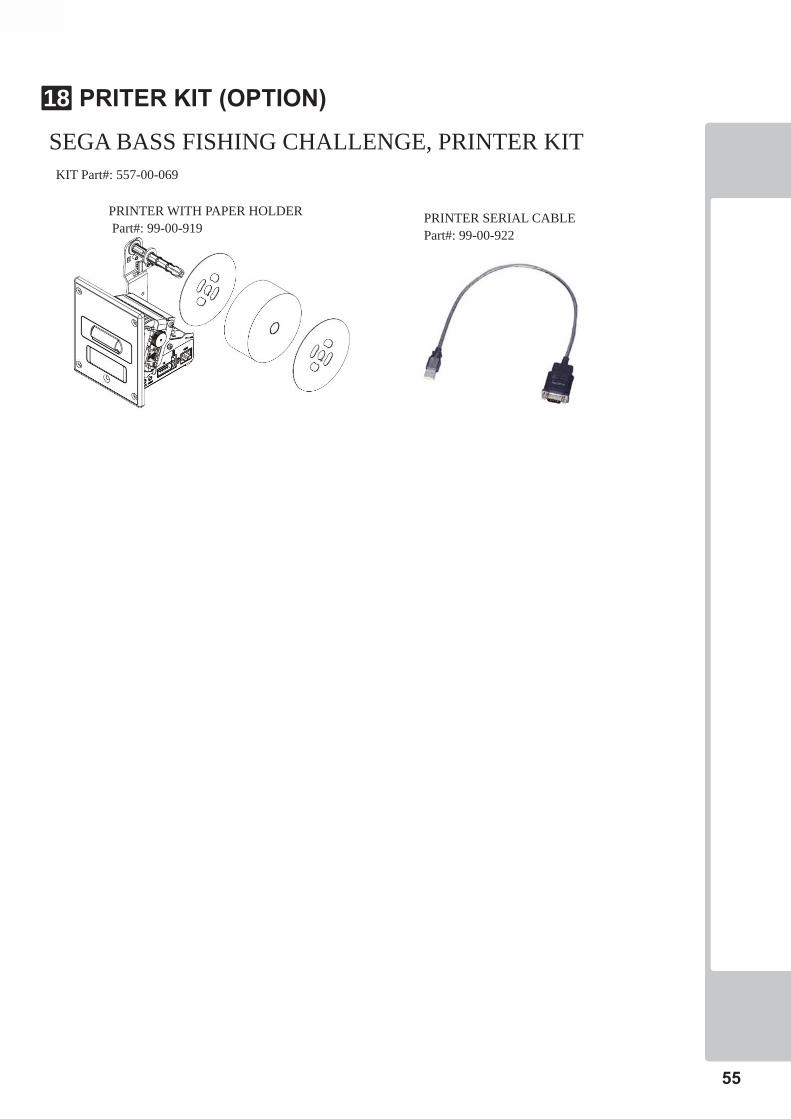
SEGA BASS FISHING CHALLENGE, PRINTER KIT
PRITERKIT(OPTION)1618
PRINTER WITH PAPER HOLDER Part#: 99-00-919
PRINTER SERIAL CABLEPart#: 99-00-922
KIT Part#: 557-00-069

18LICEN
SE MA
RK
56
1) Take 3 screws off to remove DBA door from cabinet.
DBA DOOR
2) Insert paper holder to printer as below angle.
3) Place PRINTER PANEL that will tight together with mounting PRINTER. Make sure do not loose it.
PRINTER PANEL
For Paper Roll order, ask SEGA Amusement USA for details
PRINTERKITINSTALLATION(EXAMPLE)1619
PRINTER
KIT(O
PTION)
19
57
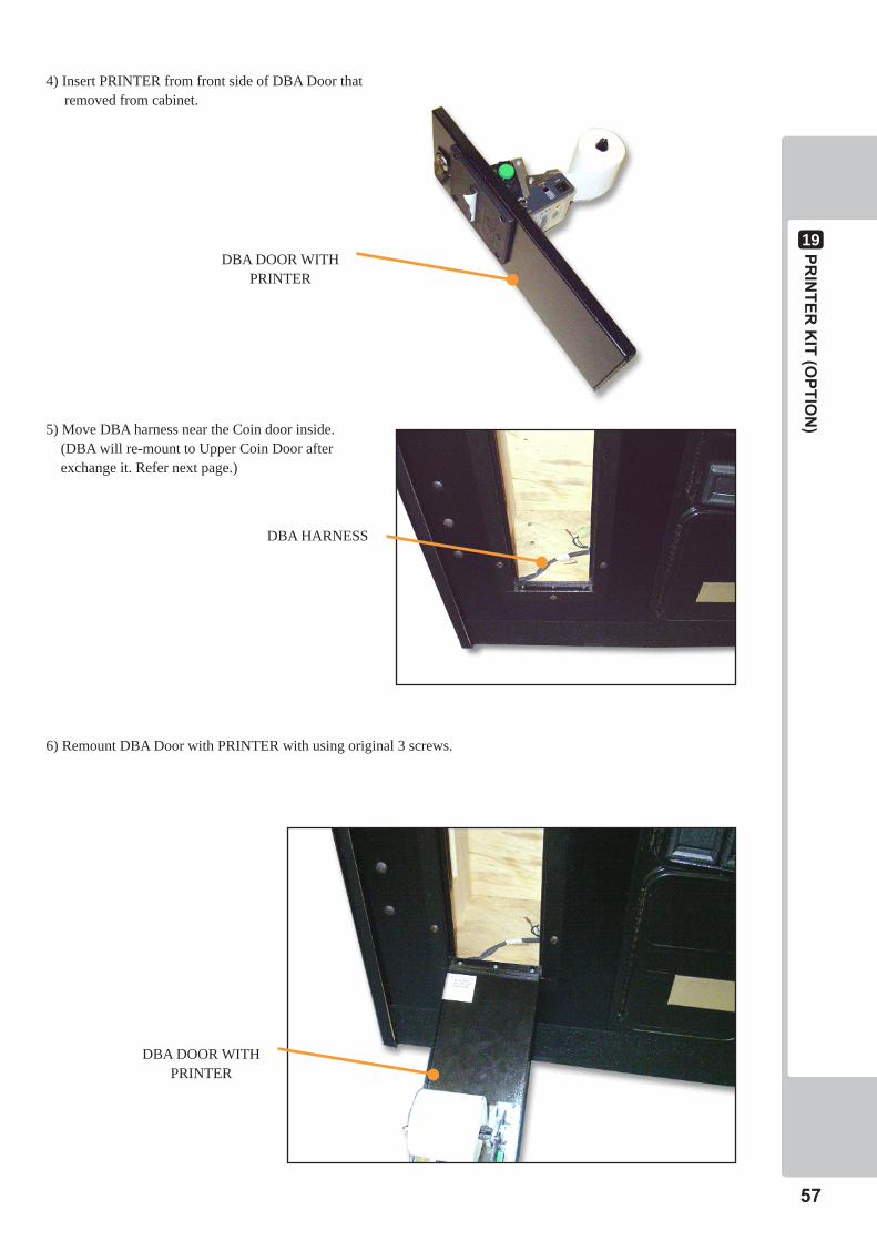
4) Insert PRINTER from front side of DBA Door that removed from cabinet.
5) Move DBA harness near the Coin door inside. (DBA will re-mount to Upper Coin Door after exchange it. Refer next page.)
6) Remount DBA Door with PRINTER with using original 3 screws.
DBA HARNESS
DBA DOOR WITH PRINTER
DBA DOOR WITH PRINTER
19PRINTER
KIT(O
PTION)
58
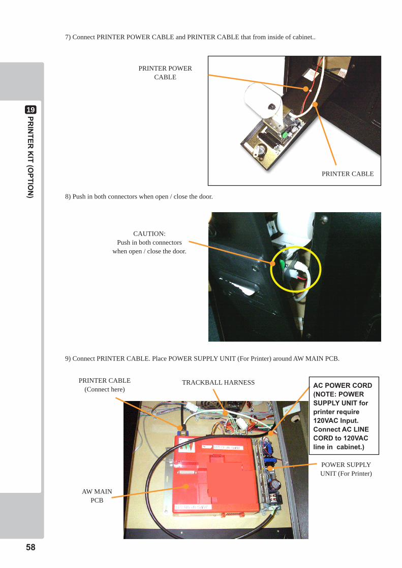
PRINTER POWER CABLE
PRINTER CABLE
7) Connect PRINTER POWER CABLE and PRINTER CABLE that from inside of cabinet..
8) Push in both connectors when open / close the door.
CAUTION:Push in both connectors
when open / close the door.
9) Connect PRINTER CABLE. Place POWER SUPPLY UNIT (For Printer) around AW MAIN PCB.
PRINTER CABLE (Connect here)
POWER SUPPLYUNIT (For Printer)
AW MAIN PCB
TRACKBALL HARNESS ACPOWERCORD(NOTE:POWERSUPPLYUNITforprinterrequire120VACInput.ConnectACLINECORDto120VAClineincabinet.)

PRINTER
KIT(O
PTION)
19
59
10) TRACKBALL HARNESS connect to EX I/O connector. Then connect to connector that come from original trackball.
TRACKBALL HARNESS
Other side of connector on TRACKBALL HARNESS need to connect to connector that from
original Trackball.
11) Exchange Upper Coin Door as below type (DBA ready type) that able to mount DBA unit.
DO NOT USE THIS DEVICEfor SEGA Bass Fishing Challenge.
19PRINTER
KIT(O
PTION)
60
NOTES
PRINTER
KIT(O
PTION)
19
61
NOTES
GAME WARRANTY POLICYYour new SEGA PRODUCT is covered for a period of ninety (90) days from the date of the shipment. This certifies that all Printed Circuit boards, power supplies and monitors are to be free of defects in workmanship or materials under normal operating conditions. This also certifies that all Interactive Control Assemblies are to be free from defects in workmanship and materials under normal operating conditions. No other product in this machine is hereby covered.Sellers sole liability in the event a warranted part described above fails shall be, at its option, to replaceor repair the defective part during the warranty period. For warranty claims, contact your SEGA Distributor.Should the seller determine, by inspection that the problem was caused by accident, misuse, neglect, alteration, improper repair, installation or testing, the warranty offered will be null and void.Under no circumstances is the seller responsible for any loss of profits, loss of use, or other damages.This shall be the exclusive written Warranty of the original purchaser expressed in lieu of all other warranties expressed or implied. Under no circumstances shall it extend beyond the period of time listed above.
PARTS WARRANTY POLICYSega Amusements USA, Inc. warrants all parts to be free from defective materials and workmanship for a period of thirty (30) days from Sega Amusements USA, Inc. invoice date unless otherwise specified in writing by Sega Amusements USA, Inc.
This limited warranty is invalid for any part that upon examination, is deemed to have been subject to misuse, improper repair or installation, neglect or violation of specification or other instructions published by Sega Amusements USA, Inc. There are no additional warranties described above.
The limited warranties described above shall be in lieu of any other warranty, express or implied, including but not limited to any implied warranty of merchantability or fitness for a particular purpose.
WARRANTIES