bedrock geology of the south island aggregates stebbings
TRANSCRIPT

Bedrock Geology of the
South Island Aggregates Stebbings Road Quarry
Kirk Hancock, B.Sc., P.Geo. BC Geological Survey – Energy, Mines and Natural Gas
Province of British Columbia
30 October, 2012


1. Introduction
South Island Aggregates [SIA] operates a bedrock aggregate quarry on Stebbings Road, 5 km south of Shawnigan Lake area, southern Vancouver Island (Fig. 1). The company has applied for a permit to use mined out areas of this quarry to treat and dispose of contaminated soils, allowing for land reclamation as mining progresses. However, concerns regarding the potential impacts on the quality of groundwater and drinking water have been raised. This report considers the bedrock geology and its relationship to groundwater at the quarry.
2. Context and purpose of report
This report summarizes a geological examination of the SIA quarry. Of particular concern is characterizing fractures in bedrock and how they could influence groundwater flows. The author performed two days of field mapping on the property in September, 2012. The investigation was undertaken at the request of the Senior Mines Inspector, Southwest Region, Ministry of Energy, Mines and Natural Gas (MEMNG).
3. Location and topography
The Stebbings Road quarry of South Island Aggregates [SIA] is located near Shawnigan Lake Road and five kilometres south of Shawnigan Lake (Fig. 1). The countryside is moderate to dense forest with numerous logging cuts in various stages of regrowth. The topography is rugged and steep in places. Cover is thin, generally less than two metres, and comprises glacial debris and soil. The SIA quarry consists of a single, open quarry in bedrock.
4. Regional geology
The SIA quarry is underlain by rocks of the Wark Gneiss complex (Fig. 2; Muller, 1980). This complex consists mainly of foliated to massive hornblende-plagioclase gneiss with minor quartz and magnetite. Locally, small lenses of limestone are infolded with the gneiss. Uranium-lead zircon geochronology (Muller, 1977) indicates the gneiss formed about 295 – 384 million years ago (Palaeozoic); potassium-argon dating (Muller 1977) indicates that the rocks were metamorphosed as recently as 163-274 million years ago (Mesozoic). The Wark Gneiss is typically in fault contact with the Colquitz Gneiss, an irregularly foliated biotite-quartz-plagioclase gneiss with mafic Wark-like inclusions. Muller (1980) suggested that both gneisses are the metamorphic equivalents of the Paleozoic Sicker Group, which underlie a large part of Vancouver Island. The Sicker Group is a several kilometer thick sequence of submarine volcanic flows, tuffs, volcanogenic mass flows and fine grained siliciclastic sedimentary rocks.
The Wark Gneiss complex consists of massive to well foliated gabbro to diorite. Grain sizes range from sub-millimetre scale to about 5 mm. In places the rock appears pristine and massive; in others it is strongly deformed with a well developed gneissic texture. The rock typically weathers buff to green-grey, and weathered surfaces usually show rock textures well. On fresh surfaces, the rock ranges from medium to dark green and grain textures are difficult to distinguish in all but the coarsest material. The rock is hard and resistant, forming hills, knobs and other prominences.

Figure 1: Location of the South Island Aggregates Stebbings Road Quarry
Victoria
Mill Bay
SIAQuarry
SIAQuarry
StebbingsRoadStebbingsRoad
Hw
y #
1
ShawniganLakeShawniganLake

Figure 2: Map showing regional geology of the Shawnigan Lake area(modified from Muller, 1980).
Figure 2: Map showing regional geology of the Shawnigan Lake area(modified from Muller, 1980).
Geology:
Dark Purple: Wark Gneiss complexLight Purple: Colquitz GneissLight Blue: LimestoneRed: Saltspring Intrusions
Geology:
Dark Purple: Wark Gneiss complexLight Purple: Colquitz GneissLight Blue: LimestoneRed: Saltspring Intrusions
SIAQuarry
SIAQuarry

Regionally, limestone forms slivers and pods within the Wark Gneiss complex. It occurs either within well developed gneissic textured parts of the complex or between major faults that cross-cut the complex. An example of the latter is at the Butler Brothers limestone quarry, 500 metres south of the SIA quarry, where limestone forms a structural slice between Wark Gneiss complex to the north and Colquitz Gneiss to the south.
Northeast of the quarry, near Mill Bay (Figs. 1, 2), granitic plugs of the Saltspring Island suite cross cut the Colquitz Gneiss; dykes related to such Saltspring bodies are developed regionally. The Saltspring Island intrusions formed approximately 410 million years ago (Devonian) (Muller, 1980; Greenwood & Mihalynuk, 2009).
5. Local Geology
The area of the SIA quarry and property were mapped as part of this study (Fig. 3). Quaternary cover, comprising glacigenic sediments and soil, is generally less than 2 m thick. Three rock types were recognized in the field: 1) medium- to coarse-grained, dark green gabbro; 2) medium- to fine-grained, medium to dark green diorite; and 3) pale green, fine-grained diorite. The first two constitute the predominant bedrock in the quarry. The relative proportion of diorite and gabbro and their relationship to each other is complex. Some textures suggest the body is in part a migmatite, whereas others show a more uniform mass of one rock type or another. As part of the Wark Gneiss complex, this is very typical. Boundaries between the gabbro and dark green diorite are transitional over several centimetres to millimetres. Neither rock type displays a gneissosity. The variability of textures is shown in Photos 1, 2 and 3.
The pale green diorite forms dykes that cross cut the gabbro and dark green diorite. A shallowly-dipping (120°/20°) one metre thick dyke is exposed in the south pit face (Photo 4). Adjacent to the dyke, a relatively wide (5-20 cm) baked contact is developed in the host .At the contact with host diorite / gabbro, a broken zone of biotite/chlorite/hornblende, 5 – 20 centimetres wide is present. The edge of the dyke has numerous thin fingers extending into the host rock, and the amount of apparent alteration increases adjacent to these fingers.
The log for a water well, drilled between the SIA site office and Shawnigan Creek, is reportedly collared in limestone. However, evidence of limestone is lacking anywhere in outcrop, and cuttings from drilling may have been misidentified.
6. Bedrock lithology and petrography
Petrographic and X-Ray diffraction [XRD] work by Applied Petrographic Services, Inc. was done on three representative samples provided by SIA from the active quarry (Jana, 2011). A brief summary of the findings is included here. Three rock samples were selected based on colour: light, medium, and dark green. The petrographic analysis classed them as tonalite, quartz diorite and hornblende diorite respectively. Based on the descriptions in the petrographic report, the writer associates the three rock types by field description to petrographic description as follows: Gabbro is the hornblende diorite; diorite is the quartz diorite; and the fine-grained diorite is the tonalite. While the writer does not know the precise location of where in the quarry the samples came from, the descriptions are consistent with the three rock types seen in the field.

11
4
56
10
9
87
32
13
13a
13b
14
15 16 16b
1217
18
19
1
20
21
22
23
30
29
28
26
27
25
24
31
D
D
D
fill
dum
p a
rea
Quarry
are
a
SIASite
Office
SIASite
Office
0 100
metres
N
Figure 3: Map showing SIA quarry area. Mapped outcrops (red) and dykes (green “D”).Approximate outline of quarry, September 2012 (yellow line).Water well (Blue dot). Base image from Google Earth.
Figure 3: Map showing SIA quarry area. Mapped outcrops (red) and dykes (green “D”).Approximate outline of quarry, September 2012 (yellow line).Water well (Blue dot). Base image from Google Earth.

Photo 1:
Showing the variable texture ofWark Gneiss complex. Notecontrasting coarse and fine grainedmaterial. Knife is 30 cm long.
Station 10
Photo 1:
Showing the variable texture ofWark Gneiss complex. Notecontrasting coarse and fine grainedmaterial. Knife is 30 cm long.
Station 10
Photo 2:
Showing blocky weathering alongfracture planes [upper left corner ofimage] plus compositionalsegregation [right of image].
Station 30
Photo 2:
Showing blocky weathering alongfracture planes [upper left corner ofimage] plus compositionalsegregation [right of image].
Station 30
Photo 3:
Showing a typical weathered outcropof massive gneiss with veinlets,fracture planes and compositionalvariation.
Photo 3:
Showing a typical weathered outcropof massive gneiss with veinlets,fracture planes and compositionalvariation.
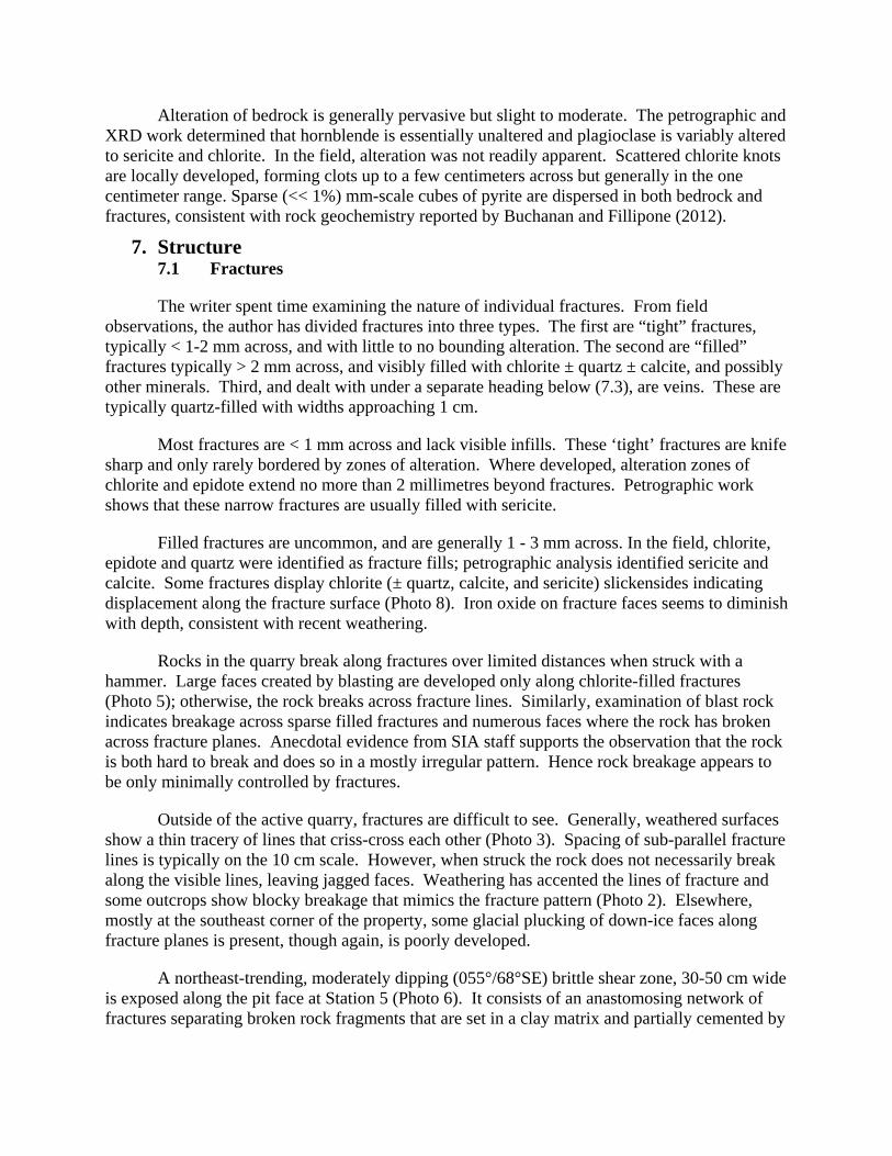
Alteration of bedrock is generally pervasive but slight to moderate. The petrographic and XRD work determined that hornblende is essentially unaltered and plagioclase is variably altered to sericite and chlorite. In the field, alteration was not readily apparent. Scattered chlorite knots are locally developed, forming clots up to a few centimeters across but generally in the one centimeter range. Sparse (<< 1%) mm-scale cubes of pyrite are dispersed in both bedrock and fractures, consistent with rock geochemistry reported by Buchanan and Fillipone (2012).
7. Structure 7.1 Fractures
The writer spent time examining the nature of individual fractures. From field observations, the author has divided fractures into three types. The first are “tight” fractures, typically < 1-2 mm across, and with little to no bounding alteration. The second are “filled” fractures typically > 2 mm across, and visibly filled with chlorite ± quartz ± calcite, and possibly other minerals. Third, and dealt with under a separate heading below (7.3), are veins. These are typically quartz-filled with widths approaching 1 cm.
Most fractures are < 1 mm across and lack visible infills. These ‘tight’ fractures are knife sharp and only rarely bordered by zones of alteration. Where developed, alteration zones of chlorite and epidote extend no more than 2 millimetres beyond fractures. Petrographic work shows that these narrow fractures are usually filled with sericite.
Filled fractures are uncommon, and are generally 1 - 3 mm across. In the field, chlorite, epidote and quartz were identified as fracture fills; petrographic analysis identified sericite and calcite. Some fractures display chlorite (± quartz, calcite, and sericite) slickensides indicating displacement along the fracture surface (Photo 8). Iron oxide on fracture faces seems to diminish with depth, consistent with recent weathering.
Rocks in the quarry break along fractures over limited distances when struck with a hammer. Large faces created by blasting are developed only along chlorite-filled fractures (Photo 5); otherwise, the rock breaks across fracture lines. Similarly, examination of blast rock indicates breakage across sparse filled fractures and numerous faces where the rock has broken across fracture planes. Anecdotal evidence from SIA staff supports the observation that the rock is both hard to break and does so in a mostly irregular pattern. Hence rock breakage appears to be only minimally controlled by fractures.
Outside of the active quarry, fractures are difficult to see. Generally, weathered surfaces show a thin tracery of lines that criss-cross each other (Photo 3). Spacing of sub-parallel fracture lines is typically on the 10 cm scale. However, when struck the rock does not necessarily break along the visible lines, leaving jagged faces. Weathering has accented the lines of fracture and some outcrops show blocky breakage that mimics the fracture pattern (Photo 2). Elsewhere, mostly at the southeast corner of the property, some glacial plucking of down-ice faces along fracture planes is present, though again, is poorly developed.
A northeast-trending, moderately dipping (055°/68°SE) brittle shear zone, 30-50 cm wide is exposed along the pit face at Station 5 (Photo 6). It consists of an anastomosing network of fractures separating broken rock fragments that are set in a clay matrix and partially cemented by

Photo 5:
Showing large blast face andfracturing
Station 5
Photo 5:
Showing large blast face andfracturing
Station 5
Photo 6:
Blast face with brittle shearzone outlined. Hammer forscale, across shear.
Station 5
Photo 6:
Blast face with brittle shearzone outlined. Hammer forscale, across shear.
Station 5
Photo 4:
Showing low angle dyke [outlined] ingabbro host. Face is approximately 8metres high.
Station 6
Photo 4:
Showing low angle dyke [outlined] ingabbro host. Face is approximately 8metres high.
Station 6Dyke

calcite. The material within the shear zone is broken and there is evidence of open spaces, but the open volume was not quantified.
There appears to be one, marginally preferred, fracture orientation of 190°/85°W. Along the south wall of the quarry, rock breaks preferentially along these surfaces. Spacing is on a one to two metre scale (Photo 7). Secondary fracture orientations show some breakage but are moderately to poorly developed. Fracture faces tend to be curvi-planar over several metres.
7.2 Veins
Few veins were seen on the SIA property. One quartz filled vein, 15 – 20 centimetres wide, with an internal, braided texture is present in the south wall of the pit at Station 4. The vein is oriented 120°/72°SW. Other veins are small, about one centimetre wide, filled with quartz with minor chlorite, epidote or calcite and typically only a few metres long (Photo 3). Some follow fractures and others do not. At one location, Station 3, a single discrete, irregular quartz rimmed vug about two centimetres long was observed adjacent to a fracture plane. Vugs or similar open spaces within veins were not seen elsewhere.
7.3 Orientation analysis
To determine trends and relationships, a total of 96 structural measurements were taken from 31 stations (Fig. 3), including orientations of 83 fractures, 7 slickenside surfaces, 5 veins, and 3 dykes (Figs. 4 and 5).
Measurements of tight fractures failed to indicate preferred orientations (Fig 4a). Combining sparse data of filled fractures and fractures with slickensides, suggests a vague pattern (Fig. 4b) with a roughly east-west group and a more north-south group. The general high dispersion of fracture orientations is consistent with a massive, intrusion-like bedrock body that has experienced multiple episodes of deformation over geological time.
Dykes and veins suggest two groups of trends: one west-northwest/east-southeast and the other north/south (Fig. 5). The west-northwest trend may reflect the regional structural trend of the gabbro block that the SIA quarry sits within. However, the number of measurements is inadequate to draw definitive conclusions.
8. Comments on the presence and absence of water in fractures.
During the site investigation no water was observed in any fractures. Although Shawnigan Creek was observed to be flowing with water, fractures in adjacent bedrock were dry (Photo 9). Furthermore, a series of bench tests were performed on rock samples from the quarry (Hoog and Weiher, 2011). Repeated wetting/drying and freeze/thaw tests determined that the rock does not absorb water and does not spall due to freezing.
The onsite water well, Ministry Well ID Plate Number 16588, was drilled east and adjacent to Shawnigan Creek, near the site office. The hole was dry to a depth of 258 feet before a fracture was penetrated and water entered the hole. At the time of the author’s investigation, the well was dry.

Figure 4: Stereonets showing fracture planes.4a) “tight” fractures. 4b) “filled” fractures.
Figure 4: Stereonets showing fracture planes.4a) “tight” fractures. 4b) “filled” fractures.
Figure 5: Stereonet showing dyke and vein planes.Green planes - dykes. Pink planes - veins.
Figure 5: Stereonet showing dyke and vein planes.Green planes - dykes. Pink planes - veins.
NN
N
E-WtrendE-Wtrend
N-StrendN-S
trend
N-StrendN-S
trend
NW-SEtrend
NW-SEtrend
Equal angle stereonet.Stereo plots generated on Stereonet 7 application, R. Allmendinger, Cornell University, USAhttp://www.geo.cornell.edu/geology/faculty/RWA/programs/stereonet-7-for-windows/
4a 4b

Photo 9:
Shawnigan Creek at SIA bridgecrossing. Showing fractures in creekparallel to hammer and flowing water.Hammer for scale, handle is 30" long.
Station 1
Photo 9:
Shawnigan Creek at SIA bridgecrossing. Showing fractures in creekparallel to hammer and flowing water.Hammer for scale, handle is 30" long.
Station 1
Photo 8:
Showing near vertical fracture face withslickensides indicating lateral motion(black arrow). Hammer for scale, handleis 30" long.
Station 3
Photo 8:
Showing near vertical fracture face withslickensides indicating lateral motion(black arrow). Hammer for scale, handleis 30" long.
Station 3
Photo 7:
Showing fracture series in quarry.Oriented at approximately190°/85°W and spaced at 1 - 2metres. Note the curvi-planarfracture surfaces: white line tracesone such surface.
Station 5
Photo 7:
Showing fracture series in quarry.Oriented at approximately190°/85°W and spaced at 1 - 2metres. Note the curvi-planarfracture surfaces: white line tracesone such surface.
Station 5
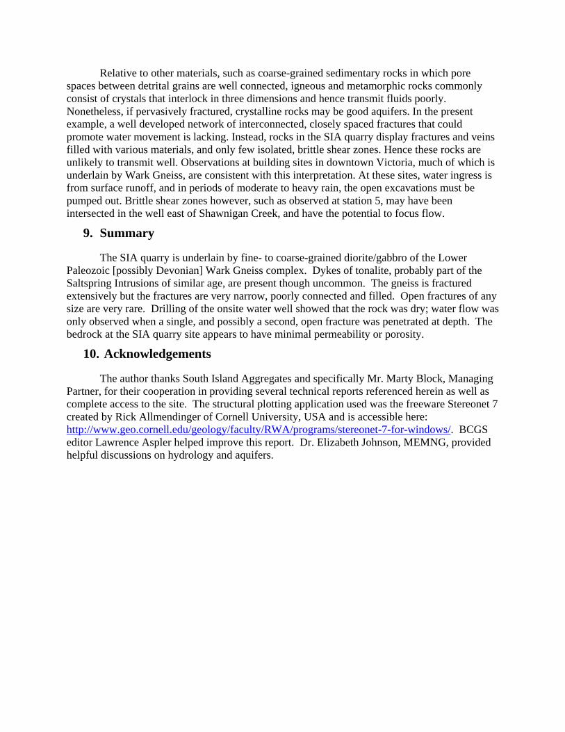
Relative to other materials, such as coarse-grained sedimentary rocks in which pore spaces between detrital grains are well connected, igneous and metamorphic rocks commonly consist of crystals that interlock in three dimensions and hence transmit fluids poorly. Nonetheless, if pervasively fractured, crystalline rocks may be good aquifers. In the present example, a well developed network of interconnected, closely spaced fractures that could promote water movement is lacking. Instead, rocks in the SIA quarry display fractures and veins filled with various materials, and only few isolated, brittle shear zones. Hence these rocks are unlikely to transmit well. Observations at building sites in downtown Victoria, much of which is underlain by Wark Gneiss, are consistent with this interpretation. At these sites, water ingress is from surface runoff, and in periods of moderate to heavy rain, the open excavations must be pumped out. Brittle shear zones however, such as observed at station 5, may have been intersected in the well east of Shawnigan Creek, and have the potential to focus flow.
9. Summary
The SIA quarry is underlain by fine- to coarse-grained diorite/gabbro of the Lower Paleozoic [possibly Devonian] Wark Gneiss complex. Dykes of tonalite, probably part of the Saltspring Intrusions of similar age, are present though uncommon. The gneiss is fractured extensively but the fractures are very narrow, poorly connected and filled. Open fractures of any size are very rare. Drilling of the onsite water well showed that the rock was dry; water flow was only observed when a single, and possibly a second, open fracture was penetrated at depth. The bedrock at the SIA quarry site appears to have minimal permeability or porosity.
10. Acknowledgements
The author thanks South Island Aggregates and specifically Mr. Marty Block, Managing Partner, for their cooperation in providing several technical reports referenced herein as well as complete access to the site. The structural plotting application used was the freeware Stereonet 7 created by Rick Allmendinger of Cornell University, USA and is accessible here: http://www.geo.cornell.edu/geology/faculty/RWA/programs/stereonet-7-for-windows/. BCGS editor Lawrence Aspler helped improve this report. Dr. Elizabeth Johnson, MEMNG, provided helpful discussions on hydrology and aquifers.

11. References Buchanan, R. and Fillipone, J. (2012): Chemical Analysis of Bedrock Sample – Stebbings Pit;
Golder Associates, Report, Project No. 09-1476-5009, 21 pages.
Greenwood, H.J. and Mihalynuk, M.G. (2009): Saltspring Island Geology adjoining quadrants of NTS 092B/11,12,13&14; BC Geological Survey, Open File 2009-11, map and notes.
Hoog, M. And Weiher, A. (2011): Outer Breakwater Rehabilitation Rock Testing; Professional Services Industries, Inc., Report #0702601-1, 2 pages.
Muller, J.E. (1977): Geology of Vancouver Island, Geological Survey of Canada, Open File 463, 2 maps plus marginal notes.
Muller, J.E. (1980): Geology, Victoria; Geological Survey of Canada, Map 1553A.
Lowen, D. (2012): Letter to the Shawnigan Residents Association, 11 pages.
Jana, D. (2011): Optical Microscopy & X-Ray Diffraction Analysis of Three Diorite–Tonalite Samples; Applied Petrographic Services, Report, APS 0611177, 18 pages.