bedienungsanleitung operating instructions notice d
TRANSCRIPT

MCW-D 50Konferenzsystem
Discussion System
Système de conférence digital sans fil
BEDIENUNGSANLEITUNG
OPERATING INSTRUCTIONS
NOTICE D’UTILISATION


MCW-D 50 – Contents 29
eng
lish
NoteThis manual is for electro-technically qualified staff. The knowledge and the precise realisation of these instructions are necessary for a smoothinstallation and security during the operation of the described products.
This manual does not include each possible case of installation, operation or maintenance. For more information please contact your beyerdynamic dealer or beyerdynamic GmbH & Co. KG.
beyerdynamic assumes no liability for errors in this documentation and for damages resulting from using this documentation and the products described in it.
Notes for potential reconsignments1. In order to avoid damages, please dispatch the microphone units in the charging case, if you need to return them. 2. If you want to return individual microphone units, please make sure that no heavy weights can damage the goosenecks through the
packaging.
1. Important Safety Instructions . . . . . . . . . . . . . . . . . . . . . . . . . . . . . . . . . . . . . . . . . . . . . . . . . . . . . . . . . . . . . . . . . . . . . . . . . . Page 30
2. Installation . . . . . . . . . . . . . . . . . . . . . . . . . . . . . . . . . . . . . . . . . . . . . . . . . . . . . . . . . . . . . . . . . . . . . . . . . . . . . . . . . . . . . . . . Page 33
3. MCW-D 50 Control Unit. . . . . . . . . . . . . . . . . . . . . . . . . . . . . . . . . . . . . . . . . . . . . . . . . . . . . . . . . . . . . . . . . . . . . . . . . . . . . . Page 333.1 Controls and Indicators . . . . . . . . . . . . . . . . . . . . . . . . . . . . . . . . . . . . . . . . . . . . . . . . . . . . . . . . . . . . . . . . . . . . . . . . Page 333.2 Setting up . . . . . . . . . . . . . . . . . . . . . . . . . . . . . . . . . . . . . . . . . . . . . . . . . . . . . . . . . . . . . . . . . . . . . . . . . . . . . . . . . . Page 343.2.1 Where to place the Control Unit . . . . . . . . . . . . . . . . . . . . . . . . . . . . . . . . . . . . . . . . . . . . . . . . . . . . . . . . . . . . . . . . . Page 343.2.2 How to connect the Antennae. . . . . . . . . . . . . . . . . . . . . . . . . . . . . . . . . . . . . . . . . . . . . . . . . . . . . . . . . . . . . . . . . . . Page 353.2.3 Audio Connection . . . . . . . . . . . . . . . . . . . . . . . . . . . . . . . . . . . . . . . . . . . . . . . . . . . . . . . . . . . . . . . . . . . . . . . . . . . . Page 353.2.4 Power Supply. . . . . . . . . . . . . . . . . . . . . . . . . . . . . . . . . . . . . . . . . . . . . . . . . . . . . . . . . . . . . . . . . . . . . . . . . . . . . . . . Page 353.2.5 How to switch the Control Unit on/off. . . . . . . . . . . . . . . . . . . . . . . . . . . . . . . . . . . . . . . . . . . . . . . . . . . . . . . . . . . . . Page 363.2.6 Channel Indication. . . . . . . . . . . . . . . . . . . . . . . . . . . . . . . . . . . . . . . . . . . . . . . . . . . . . . . . . . . . . . . . . . . . . . . . . . . . Page 363.2.7 Rack Mounting . . . . . . . . . . . . . . . . . . . . . . . . . . . . . . . . . . . . . . . . . . . . . . . . . . . . . . . . . . . . . . . . . . . . . . . . . . . . . . Page 363.2.8 Volume Control . . . . . . . . . . . . . . . . . . . . . . . . . . . . . . . . . . . . . . . . . . . . . . . . . . . . . . . . . . . . . . . . . . . . . . . . . . . . . . Page 363.2.9 Connection of Media Control System and PC . . . . . . . . . . . . . . . . . . . . . . . . . . . . . . . . . . . . . . . . . . . . . . . . . . . . . . . Page 373.3 Connecting and Positioning of remote Antennae. . . . . . . . . . . . . . . . . . . . . . . . . . . . . . . . . . . . . . . . . . . . . . . . . . . . . Page 373.4 Remote Supply of the Antenna Amplifier via the Control Unit . . . . . . . . . . . . . . . . . . . . . . . . . . . . . . . . . . . . . . . . . . . Page 38
4. Delegate and Chairman Microphone Units . . . . . . . . . . . . . . . . . . . . . . . . . . . . . . . . . . . . . . . . . . . . . . . . . . . . . . . . . . . . . . . . Page 394.1 MCW-D 521 / 523 and MCW-D 531 / 533 Microphone Units . . . . . . . . . . . . . . . . . . . . . . . . . . . . . . . . . . . . . . . . . . . Page 394.1.1 Controls and Indicators . . . . . . . . . . . . . . . . . . . . . . . . . . . . . . . . . . . . . . . . . . . . . . . . . . . . . . . . . . . . . . . . . . . . . . . . Page 394.1.2 Switching on/off . . . . . . . . . . . . . . . . . . . . . . . . . . . . . . . . . . . . . . . . . . . . . . . . . . . . . . . . . . . . . . . . . . . . . . . . . . . . . Page 414.2 Powering / Operating Time . . . . . . . . . . . . . . . . . . . . . . . . . . . . . . . . . . . . . . . . . . . . . . . . . . . . . . . . . . . . . . . . . . . . . Page 424.3 Powering with external CA 2457 Power Supply Unit . . . . . . . . . . . . . . . . . . . . . . . . . . . . . . . . . . . . . . . . . . . . . . . . . . Page 424.4 Operating Modes. . . . . . . . . . . . . . . . . . . . . . . . . . . . . . . . . . . . . . . . . . . . . . . . . . . . . . . . . . . . . . . . . . . . . . . . . . . . . Page 434.4.1 Normal Operating Mode . . . . . . . . . . . . . . . . . . . . . . . . . . . . . . . . . . . . . . . . . . . . . . . . . . . . . . . . . . . . . . . . . . . . . . . Page 434.4.2 FiFo Mode . . . . . . . . . . . . . . . . . . . . . . . . . . . . . . . . . . . . . . . . . . . . . . . . . . . . . . . . . . . . . . . . . . . . . . . . . . . . . . . . . . Page 434.4.3 Push-To-Talk Mode. . . . . . . . . . . . . . . . . . . . . . . . . . . . . . . . . . . . . . . . . . . . . . . . . . . . . . . . . . . . . . . . . . . . . . . . . . . . Page 434.4.4 Voice Activation Mode. . . . . . . . . . . . . . . . . . . . . . . . . . . . . . . . . . . . . . . . . . . . . . . . . . . . . . . . . . . . . . . . . . . . . . . . . Page 434.5 How to record the Meeting . . . . . . . . . . . . . . . . . . . . . . . . . . . . . . . . . . . . . . . . . . . . . . . . . . . . . . . . . . . . . . . . . . . . . Page 444.6 Maintenance of the MCW-D Microphone Units . . . . . . . . . . . . . . . . . . . . . . . . . . . . . . . . . . . . . . . . . . . . . . . . . . . . . . Page 44
5. Programmable Functions of the Microphone Units with the MCW-D 50 Conference Software . . . . . . . . . . . . . . . . . . . . . . . . . Page 445.1 Safety Code. . . . . . . . . . . . . . . . . . . . . . . . . . . . . . . . . . . . . . . . . . . . . . . . . . . . . . . . . . . . . . . . . . . . . . . . . . . . . . . . . Page 445.2 Function Button of the MCW-D 523 Microphone Unit. . . . . . . . . . . . . . . . . . . . . . . . . . . . . . . . . . . . . . . . . . . . . . . . . Page 455.3 Request-to-Talk Mode . . . . . . . . . . . . . . . . . . . . . . . . . . . . . . . . . . . . . . . . . . . . . . . . . . . . . . . . . . . . . . . . . . . . . . . . . Page 46
6. CD 12 Charger in CC 12 Case . . . . . . . . . . . . . . . . . . . . . . . . . . . . . . . . . . . . . . . . . . . . . . . . . . . . . . . . . . . . . . . . . . . . . . . . . Page 466.1 How to use the Charger . . . . . . . . . . . . . . . . . . . . . . . . . . . . . . . . . . . . . . . . . . . . . . . . . . . . . . . . . . . . . . . . . . . . . . . Page 466.2 Charging Process . . . . . . . . . . . . . . . . . . . . . . . . . . . . . . . . . . . . . . . . . . . . . . . . . . . . . . . . . . . . . . . . . . . . . . . . . . . . . Page 47
7. CD 13 Charger in CC 13 Case . . . . . . . . . . . . . . . . . . . . . . . . . . . . . . . . . . . . . . . . . . . . . . . . . . . . . . . . . . . . . . . . . . . . . . . . . Page 477.1 How to use the Charger . . . . . . . . . . . . . . . . . . . . . . . . . . . . . . . . . . . . . . . . . . . . . . . . . . . . . . . . . . . . . . . . . . . . . . . Page 477.2 Charging Process . . . . . . . . . . . . . . . . . . . . . . . . . . . . . . . . . . . . . . . . . . . . . . . . . . . . . . . . . . . . . . . . . . . . . . . . . . . . . Page 47
8. Battery Charging with external CA 2457 Power Supply Unit. . . . . . . . . . . . . . . . . . . . . . . . . . . . . . . . . . . . . . . . . . . . . . . . . . . Page 48
9. Trouble Shooting . . . . . . . . . . . . . . . . . . . . . . . . . . . . . . . . . . . . . . . . . . . . . . . . . . . . . . . . . . . . . . . . . . . . . . . . . . . . . . . . . . . Page 489.1 Simultaneous Operation of the MCW-D Discussion System and other 2.4 GHz Devices . . . . . . . . . . . . . . . . . . . . . . . . Page 499.1.1 Physical Laws . . . . . . . . . . . . . . . . . . . . . . . . . . . . . . . . . . . . . . . . . . . . . . . . . . . . . . . . . . . . . . . . . . . . . . . . . . . . . . . . Page 499.1.2 MCW-D and WLAN or WiFi . . . . . . . . . . . . . . . . . . . . . . . . . . . . . . . . . . . . . . . . . . . . . . . . . . . . . . . . . . . . . . . . . . . . . Page 509.1.3 MCW-D 50 and Bluetooth. . . . . . . . . . . . . . . . . . . . . . . . . . . . . . . . . . . . . . . . . . . . . . . . . . . . . . . . . . . . . . . . . . . . . . Page 509.1.4 Example for MCW-D 50, Media Control System and WLAN . . . . . . . . . . . . . . . . . . . . . . . . . . . . . . . . . . . . . . . . . . . . Page 51
10. Components. . . . . . . . . . . . . . . . . . . . . . . . . . . . . . . . . . . . . . . . . . . . . . . . . . . . . . . . . . . . . . . . . . . . . . . . . . . . . . . . . . . . . . . Page 51
11. Accessories . . . . . . . . . . . . . . . . . . . . . . . . . . . . . . . . . . . . . . . . . . . . . . . . . . . . . . . . . . . . . . . . . . . . . . . . . . . . . . . . . . . . . . . . Page 51
12. Technical Specifications. . . . . . . . . . . . . . . . . . . . . . . . . . . . . . . . . . . . . . . . . . . . . . . . . . . . . . . . . . . . . . . . . . . . . . . . . . . . . . . Page 52
EC-Declaration of Conformity. . . . . . . . . . . . . . . . . . . . . . . . . . . . . . . . . . . . . . . . . . . . . . . . . . . . . . . . . . . . . . . . . . . . . . . . . . Page 82

MCW-D 50 – Important Safety Instructions 30
1. Important Safety Instructions
Control Unit and Charger
General• READ these instructions. • KEEP these instructions.• HEED all warnings and follow all instructions.
Exemption from liability• beyerdynamic GmbH & Co. KG will not be liable if any damage, injury or accident occurs due to negligent, incorrect or inappropriate
operation of the product.
Location• The equipment must be set up so that the mains switch, mains plug and all connection on the rear of the device are easily accessible. • If you transport the equipment to another location take care to ensure that it is adequately secured and can never be damaged by being
dropped or by impacts on the equipment.
Fire hazard• Never place naked flames near the equipment.
Humidity / heat sources• Never expose the equipment to rain or a high level of humidity. For this reason do not install it in the immediate vicinity of swimming
pools, showers, damp basement rooms or other areas with unusually high atmospheric humidity. • Never place objects containing liquid (e.g. vases or drinking glasses) on the equipment. Liquids in the equipment could cause a short circuit.• Do not install near any heat sources such as radiators, heat registers, stoves or other apparatus (including amplifiers) that produce heat.
Ventilation• This equipment needs adequate ventilation. Do not cover ventilation grilles. If the heat it generates cannot be dissipated, the equipment
could be damaged or flammable materials in its immediate vicinity could be ignited. Take care to ensure that the air can circulate freelythrough the ventilation grilles and keep flammable materials away.
• Do not insert objects into the ventilation grilles or other openings. You could damage the equipment and/or injure yourself.
Connection• The equipment must be connected to a mains socket that has an earth contact. • Protect the power cord from being walked on or pinched particularly at plugs, convenience receptacles, and the point where they exit
from the apparatus.• Lay all connection cables so that they do not present a trip hazard. • Check whether the connection figures comply with the existing mains supply. Serious damage could occur due to connecting the system
to the wrong power supply. An incorrect mains voltage could damage the equipment or cause an electric shock.• Do not defeat the safety purpose of the polarised or grounding-type plug. A polarised plug has two blades with one wider than the
other. A grounding type plug has two blades and a third grounding prong. The wide blade or the third prong is provided for your safety.If the provided plug does not fit into your outlet, consult an electrician for replacement of the obsolete outlet.
• Unplug the device during lightning storms or when unused for long periods of time.• If the equipment causes a blown fuse or a short circuit, disconnect it from the mains and have it checked and repaired. • Do not hold the mains cable with wet hands. There must be no water or dust on the contact pins. In both cases you could receive an
electric shock. • The mains cable must be firmly connected. If it is loose there is a fire hazard. • Always pull out the mains cable from the mains and/or from the equipment by the plug – never by the cable. The cable could be damaged
and cause an electric shock or fire. • If the power cable is connected, avoid contact of the unit with other metallic objects. • Do not use the equipment if the mains plug is damaged. • If you connect defective or unsuitable accessories, the equipment could be damaged. Only use connection cables available from or
recommended by beyerdynamic. If you use cables you have made up yourself, all claim to warranty is null and void. • When installing the device into a 19" rack, make sure that the mains switch, mains plug and all connection on the rear of the device are
easily accessible.
Thank you for selecting the MCW-D 50 Digital wireless conference system. Please take some time to read carefully through this manual beforesetting up the equipment.This manual describes the installation and operation of the system without control and configuration via PC.The following components are needed for the operation of a system without PC:• MCW-D 50 control unit• MCW-D 521 / MCW-D 531 delegate microphone unit• MCW-D 523 / MCW-D 533 chairman microphone unit
The MCW-D 50 control unit is available in two versions:MCW-D 50-3 for discussions with a maximum of 3 participants (e.g. 2 delegates and 1 chairman) speaking simultaneously. MCW-D 50-9 for discussions with a maximum of 9 participants (e.g. 7 delegates and 2 chairmen) speaking simultaneously.
For more information about the control and configuration of the MCW-D 50 system via PC please refer to the MCW-D 50 ConferenceSoftware manual.

MCW-D 50 – Important Safety Instructions 31
eng
lish
Maintenance• Only clean the equipment with a slightly damp or dry cloth. Never use solvents as these damage the surface.
Trouble shooting and servicing• Do not open the equipment without authorisation. You could receive an electric shock. Leave all service work to authorised expert personnel. • Refer all servicing to qualified service personnel.
Charger• Use only the CD 12 charger or CA 2457 power supply unit to charge the rechargeable batteries integrated in the microphone units.• Never remove the base foam section from the CD 12 charger. There are no parts that can be serviced in the interior of the charger. • The charger has been designed for charging the rechargeable batteries in the MCW-D microphone stations. Only charge MCW-D
microphone stations and no other battery operated equipment. The batteries could explode and injure you or damage the equipment. • If you use the charger with accessories which have not been developed for it, this could result in a fire, an electric shock or physical injury. • Never try to repair the charger yourself. There is a risk of an electric shock or causing a fire. • Never use the charger as a mains power supply unit for electrical equipment.
Microphone Units
Set up• Conference microphone stations with metal casings are heavy, so always position them on a secure surface. • To align the gooseneck microphone on the microphone station and to avoid twisting it too far and causing premature wear,
always grip the microphone by the bottom flexible section never by the microphone head or by the rigid tube. The gooseneck must be bent no further than an angle of 90° maximum.
Risk of injury• If the microphone stations have a gooseneck microphone take care that you do not injure yourself on this e.g. poke it into your eye. • The charging contacts of the MCW-D microphone stations can cause damage to property, injuries or fire damage if they come into
contact with conductive material such as jewellery, keys or chains. This closes the circuit and can thus cause the material to heat up. To avoid this sort of unwanted circuit, the charging contacts must be handled with caution. This applies particularly if the microphonestations are transported in a bag or some other container together with metal objects.
Charging / rechargeable batteries• When charging the microphone station in the charger, take care to ensure that you do not injure yourself when putting the station in or
taking it out. • Only switch on the charger when you have inserted all microphone stations. Empty charging compartments should never be touched
during the charging process. You could receive an electric shock. • Avoid letting the rechargeable batteries in the microphone station become too deeply discharged. The rechargeable batteries could be
damaged and the life of them could be reduced. • If battery operated equipment is not used for a lengthy period (e.g. 1 year) the self-discharge of the battery could be accelerated. The
temperature for long-term storage should be between +10° C and +30° C. • If the microphone stations are not used for several months, the rechargeable batteries in the microphone stations should be charged up
at least twice a year in order to avoid them running out and deterioration in the performance due to self discharge.
Volume• If the participants of a meeting use a headphone with the MCW-D 50 microphone stations, please make sure that the
volume is not set too high via the MCW-D 50 Conference Software. Otherwise, the hearing of the participants could permanently be damaged.
Safety Symbols
The label shown on the left is attached to back of the unit. The symbols on this label have the following meaning:
This symbol indicates that dangerous voltage constituting a risk of electric shock is present within this unit.
This symbol indicates that there are important operating and maintenance instructions in the literature accompanying this unit.

MCW-D 50 – Important Safety Instructions 32
Special Note about Power Cables for Canada and the USA
CanadaOnly use a power cable according to CSA C22.2 No.21 and CSA C22.2 No. 42.
USAThe earthing conductor in a supply cord, or in an interconnecting cable shall have an equivalent or larger cross-sectional area that the current-carrying conductors in the supply cord or cable. With reference to earthing conductors, the insulation colour may be green orgreen/yellow.Mains Supply flexible cords shall comply with UL 817, be marked VW-1, and have an ampacity not less than the current drawn by theapparatus.
Table of cable types / cable lengths being used in the USA
Apparatus type Cord type Cord length, m b
Portable, table-top, floor standing and NISPT-2a, SPT-2, SV, SVT, SVE, SJ, SJT, SJE 1.5 minimumrack-mounted audio and video apparatus
Household musical instruments NISPT-2a, SPT-2, SV, SVT, SVE 3.0 maximum
SJ, SJT, SJE 7.5 maximum
Coffee table c SV, SVT, SVE, SJ, SJT, SJE 3.0 minimum
Undercabinet and portable apparatus with NISPT-2a, SPT-2 1.5 minimumcord storage compartment
Commercial amplifier-speakers, musical SJ, SJT, SJE 7.5 maximuminstruments and sound systems d
a Appliance wiring material construction that has been determined to be equivalent is acceptable.b The length of a flexible cord on an apparatus intended for a special installation is not prohibited from being less than specified.c A coffee-table type apparatus is a type that is finished on all four sides and intended for use in the centre of the room.d A system comprised of a number of different components found for example in a school system or language teaching system.
Control UnitFCC ID: OSDMCWD50Canada: IC: 3628A-MCWD50
Microphone UnitsFCC ID: OSDMCWD5xxCanada: IC: 3628A-MCWD5xx
NOTICE:This device complies with Part 15 of the FCC Rules [and with RSS-210 of Industry Canada].Operation is subject to the following two conditions:
(1) this device may not cause harmful interference, and (2) this device must accept any interference received, including interference that may cause undesired operation.
NOTICE:Changes or modifications made to this equipment not expressly approved by (manufacturer name) may void the FCC authorization to operate this equipment.
NOTE: This equipment has been tested and found to comply with the limits for a Class B digital device, pursuant to Part 15 of the FCCRules. These limits are designed to provide reasonable protection against harmful interference in a residential installation. This equipmentgenerates, uses and can radiate radio frequency energy and, if not installed and used in accordance with the instructions, may cause harmful interference to radio communications. However, there is no guarantee that interference will not occur in a particular installation. If this equipment does cause harmful interference to radio or television reception, which can be determined by turning the equipment offand on, the user is encouraged to try to correct the interference by one or more of the following measures:
• Reorient or relocate the receiving antenna.• Increase the separation between the equipment and receiver.• Connect the equipment into an outlet on a circuit different from that to which the receiver is connected.• Consult the dealer or an experienced radio/TV technician for help.

MCW-D 50 – Control Unit 33
eng
lish
3. MCW-D 50 Control Unit
The MCW-D 50 control unit is the heart of the system. It controls the delegate and chairman microphone units. With the standard versionof the MCW-D 50 control unit a maximum of 3 speakers (e.g. 2 delegates and 1 chairman) can speak simultaneously.
3.1 Controls and Indicators
Front
1 2 3 4 5
Power LED. LED is illuminated green when the unit is switched on.
Standby button. When this button is pressed for more than 3 seconds all switched-on microphone units are switched off.When this button is pressed shortly all allocated microphones are switched off.
Reset. This button resets the system into the switch-on state (to press the reset button use a paper clip).
LEDs to indicate the status of the receiving channels. LED is illuminated green: the channel is vacant. LED is illuminated red: the channel is occupied.
Volume control for the loudspeakers of the microphone units
1
2
3
4
5
2. Installation
The MCW-D 50 discussion system has been developed for installation on tables or 19"-mounting. When setting up the system please follow the safety instructions mentioned in chapter 1.
Furthermore, please note
• the ambient temperature of the installation site must not exceed 40°C.• there must not be exceeding dust and humidity at the installation site.• that the unit is not exposed to direct sunlight.• the connections must be protected against direct access during operation.• that there must be a strain relief of the cables.• the installation site must be protected against vibrations.

MCW-D 50 – Control Unit 34
3.2 Setting up
3.2.1 Where to place the Control Unit
• If you do not use remote antennae*, place the MCW-D 50 control unit in the room where the meeting takes place. If you use remoteantennae*, place them in the conference room.
• Do not place the MCW-D 50 control unit near digitally controlled equipment.• Do not use the control unit outside.
*Important note for the USA and Japan: At present only the use of the CA 2413 remote antenna is permitted.
RS 232 port for the connection of PC or media control system (9-pin Sub-D). Use a null modem or crossover cable (female - female).
LAN network connection for PC
Control LED for antenna powering 5 V DC (green = normal DC ; flashing red rapidly = short circuit)
Switch -10 dB / +15 dB for unbalanced input (RCA)
Input, RCA, unbalanced, for the connection of external devices such as CD players (L + R)
Output - master output, RCA, unbalanced, for the connection of external devices such as mixing consoles, sound contracting systems or recorders (L + R)
Level control for Output - master output, RCA
Switch -10 dB / +15 dB for balanced input (XLR)
Input, 3-pin XLR female, balanced, for the connection of external sound sources (+6 dBm)
Output - master output, 3-pin XLR male, balanced, for the connection of external devices such as mixing consoles, or sound contracting systems
ON/OFF-switch
Fuse
Mains supply
Connection for receiving antennae
Connection for transmitting antenna
6
7
8
9
10
10
10
11
1112
13
14
14
15
16
17
18
19
20
Rear
6 7 11 12 13 14 15 16 17 18
192019
98

MCW-D 50 – Control Unit 35
eng
lish
3.2.2 How to connect the Antennae
• Connect the receiving antennae to the antenna inputs A and B . • Connect the transmitting antenna to the antenna output . • For stand-alone operation we recommend using the CA 2411 angled rod antenna.
3.2.3 Audio Connection
• Connect the XLR or RCA master output to the input of a mixing console/amplifier.
• Always route cables running to the unit where they will not be pinched or cut by heavy or sharp objects.
3.2.4 Power Supply
• Verify that the voltage rating of the unit matches that of the AC mains outlet you are to use. If you connect the unit to the wrong voltage, you may seriously damage it.
• Always route cables running to the unit where they will not be pinched or cut by heavy or sharp objects.• Connect the MCW-D 50 control unit to the mains . The internal power supply unit of the control unit can adjust auto matically
between 100 V and 240 V at 50 - 60 Hz.
Important:• There must be an unobstructed path between the microphone units and the antennae, i.e. between the MCW-D 50
control unit and the microphone units there must not be any obstacles. The range is around 30 - 50 m. For optimumrange the surface of the table is important, wood or plastic tables are ideal, but metal tables can cause interferences and reducethe range.
• Please make sure that the minimum distance between the antennae and the microphone units is not less than 1 m.
15 11
1920
20
19
19
11 15
1818
18

MCW-D 50 – Control Unit 36
3.2.5 How to switch the Control Unit on/off
• Switch on the MCW-D 50 with the On/Off-switch on the rear. • During the first 30 seconds the MCW-D 50 control unit is started, the Power LED and the Channel LEDs are flashing red and an
operation is not yet possible. If the MCW-D 50 control unit is connected to a network via the LAN connection , the MCW-D 50 control unit will be ready for operation after approx. 20 seconds.
• The Power LED on the front will illuminate green, when the control unit is ready for operation.
• CAUTION: Always turn off the power when making input or output connections.
Rear Front
3.2.6 Channel Indication
• Depending on the configuration of the MCW-D 50 control unit 3 or more channel-LEDs will illuminate green (standard: 3 channels).
3.2.7 Rack Mounting
• When mounting the MCW-D 50 control unit into a 19"-rack housing leave 1 HU for a ventilation panel above and under thecontrol unit.
• Make sure that the mains switch, mains plug and all connection on the rear of the device are easily accessible.
3.2.8 Volume Control
• The volume of the microphone units is controlled with the virtual volume control of the MCW-D 50 Conference Software.
Important:• If the MCW-D 50 control unit is equipped with more than one module, but there are not more than 3 LEDs illuminated, please
check if individual modules have been deactivated with the MCW-D 50 Conference Software.
16
1
1 4
7
4
16 1
4

MCW-D 50 – Control Unit 37
eng
lish
3.2.9 Connection of Media Control System and PC
• If you want to connect a media control system and a PC to the MCW-D 50 control unit, connect the PC to the LAN network connectionand the media control system to the RS 232 connection .
• For the direct connection of the LAN network connection to a PC you must use a null modem or crossover cable (female - female).• The LAN settings are explained in the protocol of the MCW-D 50 Conference Software.• The IP address of the MCW-D 50 control unit is 192.168.1.102 (Port 1024).
3.3 Connecting and Positioning of remote Antennae*
The MCW-D 50 control unit can also be operated with remote antennae. Low attenuation connecting cables are available in different lengths.Please note that all three antennae have to be connected remotely. The transmitting antenna should be mounted in the centre and thereceiving antennae on the left and right hand side. The range can be increased by using a directional antenna (e.g. CA 2413, gain approx. 6 dB).Depending on the cable attenuation you should use antenna amplifiers if the cables are long.
Installation with remote antennae*
Important:• Never access the MCW-D 50 control unit via the media control system and the MCW-D 50 Conference Software simultaneously.
In this case a correct function of the system cannot be guaranteed.
6
6
7
7
(1) MCW-D 50 control unit(2) CA 2421/2422 or
CA 2431/2432 antenna cable(3) CA 2413 planar antenna(4) CA 2462 mounting kit 3/8"(5) ST 600 stand 3/8"
refer to RX A
The CA 2413 planar antenna is connected to the MCW-D 50 control unit and mounted onto a stand with the CA 2462 mounting kit.For more information refer to the “MCW-D Design Guide”.
Important:• There must be an unobstructed path between the microphone units and the antennae, i.e. between the MCW-D 50
control unit and the microphone units there must not be any obstacles. The range is around 30 - 50 m. For optimumrange the surface of the table is important, wood or plastic tables are ideal, but metal tables can cause interferences and reducethe range.
• Please make sure that the minimum distance between the antennae and the microphone units is not less than 1 m.
*Important note for the USA and Japan: At present only the use of the CA 2413 remote antenna is permitted.

MCW-D 50 – Control Unit 38
3.4 Remote Supply of the Antenna Amplifier via the Control Unit**
The antenna amplifiers can be supplied remotely via the MCW-D 50 control unit. On the rear of the MCW-D 50 control unit there is a status LED .This LED will illuminate green, when the remote supply voltage is 5 V at all antenna sockets.The LED is flashing red rapidly, when there is a short-circuit at the antenna socket. In this case check the antenna cables.The remote supply voltage of 5 V supplies the CA 2441 RT and CA 2441 T antenna amplifiers.
• Size of the room: up to 400 m2 (20 x 20)• Number of participants: 30 - 100• Antenna position: The antennae should be placed as high as possible above the table in a position close to the participants.• Alignment: Place the antennae so that they point to the participants (the convex side must point to the front).
We recommend using the CA 2441 antenna amplifier if the cable attenuation exceeds 12 or 15 dB, i.e. if the CA 2420 cable is longer than40 m or if the CA 2430 cable is longer than 60 m.
Cable attenuation of different cables in 2.4 GHz applications
Cable type
Cable length 100 m 50 m 30 m
RG 58 100 dB 50 dB 30 dB not suitable
RG 213 U 49 dB 24 dB 15 dB short cable
Aircell 7, CA 2420 41 dB 20 dB 12 dB normal cable
Ecoflex 10, CA 2430 24 dB 12 dB 7 dB long cable
Aircell 7StandardCA 2420
Ecoflex 10Low AttenuationCA 2430
Max. cable length max. 20 m= 1 x CA 2422or 2 x CA 2421
max. 40 m
Min. bending radius 25 mm 40 mm
ATTENTION:• The CA 2441 RT and CA 2441 T antenna amplifiers may only be powered with 5 V DC.• When you connect a CA 2441 RT to the TX output of the MCW-D 50 you should use a connecting cable with an
attenuation of at least 10 dB.
8
8
Important Note:To comply with FCC RF exposure compliance requirements, the following antenna installation and device-operating configuration must be satisfied. Only authorized and certified beyerdynamic systems integrators may perform the installation of antennae. There are no user serviceable parts or processes. Connect the receiving antennae to the antenna inputs A and B. Connect the transmittingantenna to the appropriate output. To maintain compliance with the FCC’s RF exposure guidelines, this transmitter and its antenna must maintain a separation distance of at least 20 centimetres from all persons.
20
20
**In the USA the use of the CA 2441 RT/T antenna amplifier is prohibited. In Japan the transmitting antenna must not be usedwith an antenna amplifier.
MCW-D 50 – Microphone Units 39
eng
lish
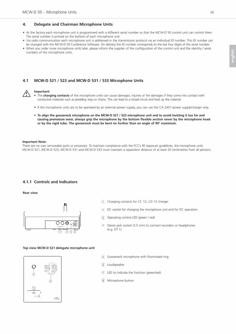
4. Delegate and Chairman Microphone Units
• At the factory each microphone unit is programmed with a different serial number so that the MCW-D 50 control unit can control them.The serial number is printed on the bottom of each microphone unit.
• Via radio communication each microphone unit is addressed in the transmission protocol via an individual ID number. This ID number canbe changed with the MCW-D 50 Conference Software. On delivery the ID number corresponds to the last four digits of the serial number.
• When you order more microphone units later, please inform the supplier of the configuration of the control unit and the identity / serialnumbers of the microphone units.
4.1 MCW-D 521 / 523 and MCW-D 531 / 533 Microphone Units
4.1.1 Controls and Indicators
Important:• The charging contacts of the microphone units can cause damages, injuries or fire damages if they come into contact with
conductive materials such as jewellery, keys or chains. This can lead to a closed circuit and heat up the material.
• If the microphone units are to be operated by an external power supply, you can use the CA 2457 power supply/charger only.
• To align the gooseneck microphone on the MCW-D 521 / 523 microphone unit and to avoid twisting it too far and causing premature wear, always grip the microphone by the bottom flexible section never by the microphone heador by the rigid tube. The gooseneck must be bent no further than an angle of 90° maximum.
Charging contacts for CC 12, CD 12 charger
DC socket for charging the microphone unit and for DC operation
Operating control LED (green / red)
Stereo jack socket (3.5 mm) to connect recorders or headphones (e.g. DT 1)
Rear view
Gooseneck microphone with illuminated ring
Loudspeaker
LED to indicate the function (green/red)
Microphone button
Top view MCW-D 521 delegate microphone unit
1
1
2
3
4
5
6
7
8
2 3 4
5
6
7
8
Important Note:There are no user serviceable parts or processes. To maintain compliance with the FCC’s RF exposure guidelines, the microphone units MCW-D 521, MCW-D 523, MCW-D 531 and MCW-D 533 must maintain a separation distance of at least 20 centimetres from all persons.

MCW-D 50 – Microphone Units 40
Gooseneck microphone with illuminated ring
Loudspeaker
LED to indicate the function (green/red)
Microphone button
Clear button to clear the delegate microphone units
Function button for optional functions (refer also to chapter 5.2)
Top view MCW-D 523 chairman microphone unit
5
6
6
7
8
9
5
7
89 10 10
Bottom view MCW-D 521 / MCW-D 523
Counter-sunk Reset button 11
11
Lateral / rear view MCW-D 531 / MCW-D 533
12
13 14 15 16
Top view MCW-D 531 delegate microphone unit
Top view MCW-D 533 chairman microphone unit
LED strips to indicate the ready-to-speak condition
Charging contacts for CC 13, CD 13 charger
Stereo jack socket (3.5 mm) to connect a recorder or headphone (e.g. DT 1)
DC socket for charging the microphone unit and for DC operation
Operating control LED (green / red)
Microphone grille
Loudspeaker
Microphone button
LED to indicate the function (red)
LED to indicate the function (green)
Clear button to clear the delegate microphone units
Function button for optional functions (refer also to chapter 5.2)
22
2323 18 1820 211922
21
12
13
14
15
16
17
18
19
20
17
17
18 1820 2119

MCW-D 50 – Setting up 41
eng
lish
4.1.2 Switching on / off
Delegate ChairmanSwitching on• The microphone units have no separate on/off switch. They are
switched on / off with the microphone button or .
MCW-D 521 / MCW-D 523• By pressing the button briefly, the microphone unit is switched on.
The LED flashes for a moment and the green LED on the rear isilluminated.
MCW-D 531 / MCW-D 533• By pressing the button briefly, the microphone unit is switched on.
The LED flashes for a moment and the green LED on the rear isilluminated.
Switching off
MCW-D 521 / MCW-D 523• By pressing the button for more than 2 seconds the microphone unit
is switched off and the LED will flash twice orange briefly. MCW-D 531 / MCW-D 533• By pressing the button for more than 2 seconds the microphone unit
is switched off and the LEDs and will flash twice briefly.
• If you press the standby button of the MCW-D 50 control unit formore than 3 seconds, you switch off all switched-on MCW-D micro-phone units within the range of the MCW-D 50 control unit.
• Furthermore, the microphone units are switched off automatically, whenthey do not receive a signal from the MCW-D 50 control unit for morethan 3 minutes.
Important:• If the microphone unit is out of range of the MCW-D 50
control unit, the LEDs or will flash red. After approx. 3 minutes the microphone unit will switch off automatically.
• If the system should fail to operate, i.e. the microphone unit isswitched on, but no sound is heard, press the reset buttonof the control unit. Should the system still fail to operate,check the audio configuration with the MCW-D 50 ConferenceSoftware. If the system still fails to operate then, please contact your beyerdynamic representative.
Important:• With the MCW-D 50 Conference Software you can
disable manual deactivation of the microphone unit.
8
8
7
7
7
3
8
2
2
3
3
7 7
MCW-D 531 delegate microphone unit
MCW-D 533 chairman microphone unit
20
20 16
21
20 21
19
19
20
20
2119
MCW-D 50 control unit

MCW-D 50 – Setting up 42
4.2 Powering / Operating Time
• The microphone units have an integrated rechargeable battery allowing an operating time of 20 hours.
• As soon as the capacity is too low for a satisfactory operation, the operating controlLED or will flash. The remaining time of operation is around 60 minutes.
• The supplied MCW-D 50 Conference Software indicates the decreasing batteryvoltage on a PC or external media control system connected to the MCW-D 50control unit.
Rear view MCW-D 521 / MCW-D 523
4.3 Powering with external CA 2457 Power Supply Unit
• The MCW-D microphone units can be also powered with the CA 2457 externalpower supply unit which can be connected to the DC socket or on therear of the microphone unit.
• As long as the power supply unit is connected, the microphone unit is alsobeing charged. Please refer also to chapter 8. Battery Charging with externalCA 2457 Power Supply Unit.
Rear view MCW-D 521 / MCW-D 523
3
3
2
2
Rear view MCW-D 531 / MCW-D 533
16
16
15
Rear view MCW-D 531 / MCW-D 533
15

MCW-D 50 – Setting up 43
eng
lish
4.4.1 Normal Operating Mode
4.4 Operating Modes
• The different operating modes such as Normal, Push-To-Talk or Voice Activation are adjusted with the MCW-D 50 Conference Software.The standard operating mode is Normal. Please refer also to the appropriate MCW-D 50 Conference Software manual.
• Press the microphone button or to switch on the gooseneckmicrophone.
• MCW-D 521 / 523: Red ring of the gooseneck microphone is illuminated and the LED is illuminated green: The microphone isready for speaking.MCW-D 531 / 533: Red LED strips on both sides are illuminatedand the LED is illuminated green: The microphone is ready forspeaking.
• Using the MCW-D 50-3 control unit 3 participants (e.g. 2 delegates and1 chairman) can speak simultaneously. Using the MCW-D 50-9 up to 9participants (e.g. 8 delegates and 1 chairman) can speak simul taneously.
Important:• If the number of open microphones is exceeded, a
microphone can only be switched on manually whenanother microphone unit has been switched off.
MCW-D 521 delegate unit MCW-D 523 chairman unit
8
7
7
8
8
7
MCW-D 531 delegate unit
MCW-D 533 chairman unit
20 2119
12
21
19
20 2119
4.4.2 FiFo Mode
• If the microphone units operate in the FiFo mode (first in - first out), the microphone unit that was switched on first, will be switched offwhen another microphone unit is switched on and the number of open microphones (NOM) will be exceeded.
4.4.3 Push-To-Talk Mode
• If the microphone units operate in the Push-To-Talk mode (PTT) the microphone button must be pressed as long as someone speaks intothe microphone.
4.4.4 Voice Activation Mode
• If the microphone units operate in the Voice Activation mode, the microphone units are switched on via voice control. That is the micro-phone unit is switched on as soon as someone speaks into the microphone. In this case it is not necessary to press the microphone button.
Important:• The threshold and the hold time can be configured with the MCW-D 50 Conference software for all microphone units.

MCW-D 50 – Setting up 44
4.5 How to record the Meeting
• For recording the meeting you can connect a recorder (e.g. a laptop with thesteno-s Conference and Recording software) to the documentation outputor .
• The volume can be adjusted with a PC using the MCW-D 50 Conference software.
• Instead of a recorder it is also possible to connect a headphone to the documentation output or . We recommend an impedance of 600 Ω.Although a lower impedance does not damage the microphone unit, the head-phone operation, however, can be disturbed.
4.6 Maintenance of the MCW-D Microphone Units
• For cleaning the MCW-D microphone units when they are slightly dirty (finger prints, dust, jam or juice) use a soft, damp cloth, spongeor brush and a liquid cleaning agent.
• Before cleaning the surface it must be moistened thoroughly. Afterwards it must be cleaned with a damp cloth. • Make sure not to allow any water to enter the unit. • For dirt caused by mineral oils and fats, animal and vegetable fats use spirit, isopropyl alcohol or benzine.• For dirt caused by ballpoint pens, typewriter ribbons or carbon paper use isopropyl alcohol or spirit.• Clean the charging contacts of the microphone units with spirit or isopropyl alcohol from time to time.• Clean the supplied pop shield with clear water. Make sure that it is completely dry before you put it on the microphone again.
4
4
4
5. Programmable Functions of the Microphone Units with the MCW-D 50 Conference Software
The functions of the microphone units described in the following are only available, when they have been programmed with theMCW-D 50 Conference software before. Please refer to the MCW-D 50 Conference Software manual.
5.1 Safety Code
By using the MCW-D 50 Conference software an alphanumerical code can be entered for the MCW-D microphone units and the MCW-D 50 control unit within one system. This will increase the safety against unauthorised listening. Microphone units which do nothave this code are not recognised by the control unit and will be deactivated.
Lateral view MCW-D 531 / MCW-D 533
Rear view MCW-D 521 / MCW-D 523
14
14
14

MCW-D 50 – Setting up 45
eng
lish
5.2 Function button of the MCW-D 523 / MCW-D 533 Chairman Microphone Unit
Depending on the configuration the following functions are possible with thefunction button or : mute, clear or priority. The function button can be configured via the control unit with the MCW-D 50 Conference software.1. Normal
All delegate microphone units will be cleared and the microphone of thechairman unit will be switched on. The delegates can switch on their micro-phones again, when the chairman switches off his microphone.
2. MuteAll delegate microphone units which were activated before, will be mutedwhen the chairman is speaking and will be reactivated when the chairmanswitches off his microphone.
3. ClearAll delegate microphone units are cleared and can be switched on afterwards.
4. How to mute Aux-In portsFirst push mutes the port, the next one enables it, third one mutes again etc.If the chairman presses the priority button, the audio signal at the Aux Inputof the MCW-D 50 control unit will be muted. The LED or of the chairman unit will start flashing red (slowly). When the chairman turns on hismicrophone, the LED or will flash green (slowly). If the chairman turnsoff priority the LED or will illuminate green permanently, if the micro-phone is still on.
5. How to mute Aux-In ports & clear all active delegate unitBy pressing the priorty button a second time, AUX-In muting will be released.By pressing the priority button a third time, the Aux-In ports will be mutedand all active delegate units will be cleared again, etc.If the chairman presses the priority button, the audio signal at the Aux Inputof the MCW-D 50 control unit will be muted and all delegate units will becleared. The LED or of the chairman unit will start flashing red (slowly).When the chairman turns on his microphone, the LED or will flashgreen (slowly). If the chairman turns off priority the LED or will illuminate green permanently, if the microphone is still on.
6. How to mute Aux-Out portsFirst push mutes the port, the next one enables it, third one mutes again etc.If the chairman presses priority, the audio signal at the Aux Output of thecontrol unit will be muted. The LED or of the chairman unit will startflashing red (slowly). When the chairman turns on his microphone, the LEDor will flash green (slowly). If the chairman turns off priority the LED or
will illuminate green permanently, if the microphone is still on.7. “COM Message” Function
A command is sent via the RS 232 serial interface from the MCW-D 50 controlunit and a programmed function is carried out via a media control system forinstance (e.g. light control).
8. CustomTwo different commands according to the duration of the push< 1 second = command “Short press string” is transmitted> 1 second = command “Long press string” is transmittedThese commands can be set individually with the MCW-D 50 ConferenceSoftware.
MCW-D 523 Chairman microphone unit
10
10
7
7
7
7
7
7
7
7
7
7
MCW-D 533 Chairman microphone unit
23
23
20
20
20
20
21
21
21
21
21
21
21

MCW-D 50 – Setting up 46
5.3 Request-to-Talk Mode
• This operating mode is only possible in conjunction with a PC using the MCW-D 50 Conference software or media control system (AMX®, Crestron®,Cue etc.).
• The request-to-talk is registered in the system by pressing the microphone button of the microphone unit.
• The allocation is made by the operator at the PC or touch screen of the mediacontrol system.
• The LED is illuminated red to indicate the request-to-talk. • If you press the microphone button again the request-to-talk is cleared. The
LED goes out.
MCW-D 521 delegate microphone unit
7
8
8
7
7
8
6. CD 12 Charger in CC 12 Case
• With the CD 12 charger integrated in the CC 12 transport case, it is possible to charge a maximum of 10 MCW-D 521 / MCW-D 523microphone units. The battery state can be seen from the outside through a window.
• The CC 12 transport case can be extended with another CD 12 charger for 10 microphone units. Because of a possible instability morethan two CD 12 chargers must not be piled up.
• The CD 12 charger has a compartment for storing accessories such as headphones.
6.1 How to use the Charger
• To achieve a 100% battery capacity all microphone units should have 2 complete charging cycles (charging and discharging) at least.Only after several charging and discharging cycles the rechargeable batteries will achieve their full capacity.
• MCW-D 521 / 523 microphone units are fitted with high-performance nickel-metal hybrid (NiMH) batteries. These guarantee operatingtimes of approx. 20 hours. It takes about two hours to recharge the two systems.
• The service life of the batteries largely depends on the manner in which they are looked after and on how well the user recharges them.To extend the service life of the batteries for as long as possible, the following charging cycle is recommended:– Do not keep the microphone units in the charging case when it is switched on.– Only put the microphone units in the charging case before a conference / application and fully charge them until the “fully charged”
status is shown.– In particular, when the microphone units are inserted, the charging case should not be constantly switched on and off. For each
charging cycle, there is an initial 5-minute charge to check the battery status. If the case with the microphone units is switched on every day (for example, because the mains is switched off automatically or by a cleaner), the microphone units will be slowly but constantly overcharged and this will damage the batteries.
– The NiMH batteries used minimise the so-called “memory effect” but their capacity is reduced when they are only partially discharged on a regular basis. For this reason, the microphone units should be fully discharged every three months until they switch off automatically. They can then be fully recharged. This procedure can, if necessary, be repeated a second time.
– If, despite this measure, the microphone unit does not operate for a sufficiently long period of time, the battery has reached the end of its service life and must be replaced. The typical service life of the battery is greatly dependent on whether or not the above points are observed. This is why batteries are not covered by warranties. If the above points are observed, a battery typically has a service life of at least two years or 1000 complete charging cycles, depending on which occurs first.
MCW-D 531 delegate microphone unit
20 2119

MCW-D 50 – Setting up 47
eng
lish
7. CD 13 Charger in CC 13 Case
• With the CD 13 charger integrated in the CC 13 transport case, it is possible to charge a maximum of 12 MCW-D 531 / MCW-D 533microphone units. The battery state can be seen from the outside through a window.
• The CC 13 transport case can be extended with another CD 13 charger for 12 microphone units. Because of a possible instability morethan two CD 13 chargers must not be piled up.
• The CD 13 charger has a compartment for storing accessories such as headphones.• The top foam cover inside the CD 13 charger is used as transportation safety device and must be removed before and during the
charging process.
7.1 How to use the Charger
• To achieve a 100% battery capacity all microphone units should have 2 complete charging cycles (charging and discharging) at least.Only after several charging and discharging cycles the rechargeable batteries will achieve their full capacity.
• MCW-D 531 / 533 microphone units are fitted with high-performance nickel-metal hybrid (NiMH) batteries. These guarantee operatingtimes of approx. 30 hours. It takes about 3.5 hours to recharge.
• The service life of the batteries largely depends on the manner in which they are looked after and on how well the user recharges them.To extend the service life of the batteries for as long as possible, the following charging cycle is recommended:– Do not keep the microphone units in the charging case when it is switched on.– Only put the microphone units in the charging case before a conference / application and fully charge them until the “fully charged”
status is shown.– In particular, when the microphone units are inserted, the charging case should not be constantly switched on and off. For each
charging cycle, there is an initial 5-minute charge to check the battery status. If the case with the microphone units is switched on every day (for example, because the mains is switched off automatically or by a cleaner), the microphone units will be slowly but constantly overcharged and this will damage the batteries.
– The NiMH batteries used minimise the so-called “memory effect” but their capacity is reduced when they are only partially discharged on a regular basis. For this reason, the microphone units should be fully discharged every three months until they switch off automatically. They can then be fully recharged. This procedure can, if necessary, be repeated a second time.
– If, despite this measure, the microphone unit does not operate for a sufficiently long period of time, the battery has reached the end of its service life and must be replaced. The typical service life of the battery is greatly dependent on whether or not the above points are observed. This is why batteries are not covered by warranties. If the above points are observed, a battery typically has a service life of at least two years or 1000 complete charging cycles, depending on which occurs first.
6.2 Charging Process
1. Connect the charger to AC power and switch it on. The switch will illuminate.2. Put the switched-off microphone units into the charging compartments. If microphone units are switched on, they are switched off
automatically. When the microphone units are used again, they must be switched on.3. The charging process is indicated by the gooseneck LED ring and can be seen from the outside through a window.
a) Gooseneck LED ring is flashing red. . . . . . . . . . . . . . . . . . . Battery is chargedb) Gooseneck LED ring illuminates red permanently . . . . . . . . Battery is fullc) Gooseneck LED ring is flashing red rapidly . . . . . . . . . . . . . Error
Note:• If an error has occurred, try to restart the charging process. If the LEDs are still flashing rapidly, please contact your
beyerdynamic dealer.• After some time the capacity of the rechargeable batteries is reduced technically. This will reduce the operating time.• It is normal that the rechargeable batteries are heated up during the charging process.• Clean the charging contacts with spirit or isopropyl alcohol from time to time.
7.2 Charging Process
1. Remove the transportation safety device. Connect the charger to AC power and switch it on. The switch will illuminate.2. Put the switched-off microphone units into the charging compartments. If microphone units are switched on, they are switched off
automatically. When the microphone units are used again, they must be switched on.3. The charging process is indicated by the gooseneck LED ring and can be seen from the outside through a window.
a) Gooseneck LED ring is flashing red. . . . . . . . . . . . . . . . . . . Battery is chargedb) Gooseneck LED ring illuminates red permanently . . . . . . . . Battery is fullc) Gooseneck LED ring is flashing red rapidly . . . . . . . . . . . . . Error
Note:• The aluminium sheet which is used as a cover for the battery compartment at the bottom of the MCW-D 53x microphone unit
can heat up during the charging process. This is the reason why you should only touch the top of the microphone unit when removing it from the charging compartment; otherwise you can burn your hand.
• If an error has occurred, try to restart the charging process. If the LEDs are still flashing rapidly, please contact your beyerdynamic dealer.
• After some time the capacity of the rechargeable batteries is reduced technically. This will reduce the operating time.• It is normal that the rechargeable batteries are heated up during the charging process.• Clean the charging contacts with spirit or isopropyl alcohol from time to time.

MCW-D 50 – Setting up 48
8. Battery Charging with external CA 2457 Power Supply Unit
• The MCW-D microphone units can also be charged with the external CA 2457 power supply unit, which is connected to the DC socket or .
• The charging process is indicated by the operating control LED or .LED indication during charging the battery:a) Operating control LED is flashing red . . . . . . . . . . . . . . . Battery is chargedb) Operating control LED illuminates red permanently . . . . Battery is fullc) Operating control LED is flashing red rapidly. . . . . . . . . . Error
Important:• After some time the capacity of the rechargeable batteries is reduced
technically. This will reduce the operating time.• It is normal that the rechargeable batteries are heated up during the
charging process. • When the battery is completely empty, the charging time is around
5 hours with the MCW-D 521 / 523 and approx. 7 hours with theMCW-D 531 / 533.
• If the microphone unit is switched on during the charging process, theLED or will illuminate green.
2
2
3
3
Rear view MCW-D 521 / 523
9. Trouble Shooting
If problems occur that you do not find listed below, reset the MCW-D system to the standard configuration with the MCW-D 50Conference software. Please refer to the appropriate manual.
Problem
LED or flashes red rapidly
Power LED or flashes
Microphone unit goes off
Allocation is not possible
Microphone unit cannot be switched on
Possible Cause
• Control unit is not switched on • Microphone unit is not within the range
of the control unit• Frequency bands have been
configured incorrectly
• Battery is almost empty• Low battery warning to indicate that the
battery is almost empty
• Check if the battery is still full• PIN Code is activated
• All channels are occupied• Check the number of open microphones
(NOM) with the MCW-D 50 Conferencesoftware
• Microphone unit is not within the rangeof the control unit
• Check the adjusted frequency bands
• Interference caused by WLAN
• System operates in the PC controlled mode (Controller)
• Control unit is not switched on• Check the number of open microphones
(NOM) with the MCW-D 50 Conferencesoftware
• Check the battery • Microphone unit is not within the range
of the control unit
Solution
• Switch on the control unit• Reduce the distance between
control unit and microphone units• Check the adjusted frequency bands
with the MCW-D 50 ConferenceSoftware
• Recharge the battery inside the micro-phone unit
• If the battery is empty, recharge it • Deactivate PIN Code
• Switch off an activated microphone• If possible increase the number of open
microphones (NOM) with the MCW-D 50Conference software
• Reduce the distance between control unit and microphone units
• Use the standard adjustments mentioned in the MCW-D 50Conference manual
• Select another frequency band for theRF module(s) with the MCW-D 50Conference Software
• Set the system into the autonomousoperating mode with the MCW-D 50Conference Software
• Switch on the control unit• If possible increase the number of
open microphones (NOM) with theMCW-D 50 Conference software
• If the battery is empty recharge it • Reduce the distance between
control unit and microphone units
7
3
Rear view MCW-D 531 / 533
15
15
16
3 16
16
16
20

MCW-D 50 – Trouble Shooting 49
eng
lish
Problem
Loudspeaker of the microphone unit doesnot work
Microphone unit cannot be switched off
Documentation output does not work
Feedback
Interferences; noise
Short drop-outs
Possible Cause
• Check the volume adjustment with theMCW-D 50 Conference Software
• “Disable Manual Power Off” function is activated
• Operating mode Push-To-Talk or Voiceactivated is active
• Crash of the microcontroller inside themicrophone unit
• Microphone unit is not switched on• Headphone is not connected
properly• Check the volume adjustment with the
MCW-D 50 Conference Software
• Check the external loudspeakers
• Check the audio level
• Microphone unit is not within the rangeof the control unit
• Check the antenna positioning and theantenna cable
• Check the line of sight between micro-phone unit and antenna
• Interferences caused by devices such asWireless LAN
Solution
• Increase the volume with the MCW-D 50 Conference Software or theVolume control of the MCW-D 50 control unit
• Deactivate “Disable Manual Power Off”function with the MCW-D 50Conference Software
• Deactivate the operating mode Push-To-Talk or Voice activated with theMCW-D 50 Conference Software
• Switch off the microphone units via thecontrol unit by pressing theClear/Standby button more than 3 seconds.
• Switch off the control unit. The micro-phone units will go off after approx. 3 minutes.
• Press the counter-sunk Reset button onthe bottom of the microphone unit.
• Switch on the microphone unit • Connect the headphone properly
• Increase the volume with the MCW-D 50 Conference Software orwith the volume control of the MCW-D 50 control unit
• Correct the volume and position of theloudspeaker
• Reduce the input level of the control unit
• Reduce the distance between control unit and microphone units
• If necessary use an antenna amplifier
• Remove obstacles between microphoneunits and antennae; do not place anyobjects in front of the antennae of thecontrol unit
• Select another frequency band for theRF module(s) with the MCW-D 50Conference Software. Refer also tochapter 9.1.
9.1 Simultaneous Operation of the MCW-D Discussion System and other 2.4 GHz Devices(e.g. WLAN, Bluetooth)
9.1.1 Physical Laws
Due to many physical laws it is not possible to guarantee a simultaneous interference-free operation of different devices using the samefrequency band. Radio devices operating in the same frequency band will always disturb each other (the function can be disturbed as well).
For the use of UHF wireless microphones it is known that 2 devices can never be operated on the same frequency. It is only possible tooperate a certain number of compatible radio devices within a defined frequency band.
This applies also to the 2.4 GHz-ISM band (2400 MHz - 2484 MHz). Due to digital transmission techniques and various transmission standards it is possible, but not recommended, to operate certain devices simultaneously within the same frequency band.

MCW-D 50 – Trouble Shooting 50
9.1.2 MCW-D and WLAN or WiFi
Like WLAN, the MCW-D 50 system uses the same bandwidth of approx. 22 MHz for each RF channel (Low, Mid, High). This results in threecompatible RF channels in the 2.4 GHz-ISM band. These are theoretically:
Compatible channel 1: 2400 MHz - 2428 MHz (theoretical mid frequency: 2414 MHz)Compatible channel 2: 2428 MHz - 2456 MHz (theoretical mid frequency: 2442 MHz)Compatible channel 3: 2456 MHz - 2484 MHz (theoretical mid frequency: 2470 MHz)
The MCW-D 50 system uses RF channels (Low, Mid, High) compatible to each other. For WLAN the user has to configure compatible RF channels.
Frequencies MCW-D 50 / WLAN
MCW-D 50 WLANChannel . . . . . . . . . . . . . . . . . . Centre frequency Channel . . . . . . . . . . . . . . . . . . Centre frequencyLow . . . . . . . . . . . . . . . . . . . . . . 2412 MHz 1 . . . . . . . . . . . . . . . . . . . . . . . . 2412
2 . . . . . . . . . . . . . . . . . . . . . . . . 24173 . . . . . . . . . . . . . . . . . . . . . . . . 24224 . . . . . . . . . . . . . . . . . . . . . . . . 24275 . . . . . . . . . . . . . . . . . . . . . . . . 2432
Mid . . . . . . . . . . . . . . . . . . . . . . 2438 MHz 6 . . . . . . . . . . . . . . . . . . . . . . . . 24377 . . . . . . . . . . . . . . . . . . . . . . . . 24428 . . . . . . . . . . . . . . . . . . . . . . . . 24479 . . . . . . . . . . . . . . . . . . . . . . . . 245210 . . . . . . . . . . . . . . . . . . . . . . . 2457
High . . . . . . . . . . . . . . . . . . . . . 2464 MHz 11 . . . . . . . . . . . . . . . . . . . . . . . 246212 . . . . . . . . . . . . . . . . . . . . . . . 246713 . . . . . . . . . . . . . . . . . . . . . . . 247214 . . . . . . . . . . . . . . . . . . . . . . . 2484
You can easily recognise that the individual WLAN channels overlap considerably due to their bandwidth. All neighbouring channels (e.g. channel 1 & 2 or channel 7 & 8) cannot be used simultaneously, because they would disturb each other. Furthermore, channel 12 and13 are not approved for the use in the USA. In general, these channels are not used either. Within the remaining frequency bands only theWLAN channels 1, 6 and 11 can be used simultaneously.
For this reason the WLAN channels 1, 6 and 11 were selected for the RF channels Low, Mid and High used for the MCW-D 50 discussionsystem. Due to this frequency compatibility the MCW-D 50 system is operated WLAN-friendly.Due to careful frequency planning it is possible to operate one MCW-D 50-3 control unit with more than 4,000 microphone units and amaximum of two WLAN devices nearby simultaneously.
More tips for installation• Keep a minimum distance of approx. 5 m between WLAN devices (e.g. Router, Repeater) and the transmitting and receiving antennae of
the MCW-D 50 control unit. • The distance between laptops with activated WLAN interface does not influence the audio transmission of the microphone units as long
as there is no active data traffic. • We recommend using different RF channels for WLAN or WiFi and MCW-D 50 channels. The distance between the WLAN and
MCW-D 50 channels should be as large as possible.• The channels of the MCW-D 50 discussion system can be selected with the supplied MCW-D 50 Conference Software.
9.1.3 MCW-D 50 and Bluetooth
• Bluetooth devices make use of the whole 2.4 GHz range with changing carrier frequencies (frequency hopping). • Interferences caused by Bluetooth devices (including microwave ovens) in normal operation can be excluded due to different measures
inside the MCW-D 50 system and an advanced transmission protocol.• It cannot be excluded, however, that an exisisting Bluetooth data traffic will be intefered by MCW-D 50.
2400 MHz Low Mid High 2484 MHz
Frequency /MHz
MCW-D 50 – Trouble Shooting 51
eng
lish
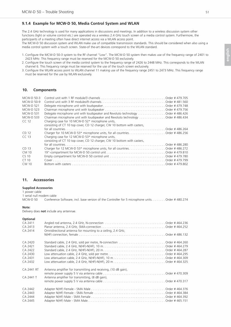
9.1.4 Example for MCW-D 50, Media Control System and WLAN
The 2.4 GHz technology is used for many applications in discussions and meetings. In addition to a wireless discussion system other functions (light or volume control etc.) are operated via a wireless 2.4 GHz touch screen of a media control system. Furthermore, the participants of a meeting often have direct internet access via a WLAN access point.The MCW-D 50 discussion system and WLAN make use of compatible transmission standards. This should be considered when also using amedia control system with a touch screen. State-of the-art devices correspond to the WLAN standard.
1. Configure the MCW-D 50-3 system to the RF channel “Low”. The MCW-D 50 system then makes use of the frequency range of 2401 to2423 MHz. This frequency range must be reserved for the MCW-D 50 exclusively.
2. Configure the touch screen of the media control system to the frequency range of 2426 to 2448 MHz. This corresponds to the WLANchannel 6. This frequency range must be reserved for the use of the touch screen exclusively.
3. Configure the WLAN access point to WLAN channel 11 making use of the frequency range 2451 to 2473 MHz. This frequency rangemust be reserved for the use by WLAN exclusively.
10. Components
MCW-D 50-3 Control unit with 1 RF module/3 channels . . . . . . . . . . . . . . . . . . . . . . . . . . . . . . . . . . . . . Order # 479.705MCW-D 50-9 Control unit with 3 RF modules/9 channels . . . . . . . . . . . . . . . . . . . . . . . . . . . . . . . . . . . . . Order # 481.560MCW-D 521 Delegate microphone unit with loudspeaker . . . . . . . . . . . . . . . . . . . . . . . . . . . . . . . . . . . . Order # 479.748MCW-D 523 Chairman microphone unit with loudspeaker . . . . . . . . . . . . . . . . . . . . . . . . . . . . . . . . . . . Order # 479.756MCW-D 531 Delegate microphone unit with loudspeaker and Revoluto technology . . . . . . . . . . . . . . . . Order # 486.426MCW-D 533 Chairman microphone unit with loudspeaker and Revoluto technology . . . . . . . . . . . . . . . Order # 486.434CC 12 Charging case for 10 MCW-D 52* microphone units,
consisting of CT 10 top cover, CD 12 charger, CW 10 bottom with casters,for all countries. . . . . . . . . . . . . . . . . . . . . . . . . . . . . . . . . . . . . . . . . . . . . . . . . . . . . . . . . . Order # 486.264
CD 12 Charger for 10 MCW-D 53* microphone units, for all countries . . . . . . . . . . . . . . . . . . . . . Order # 486.256CC 13 Charging case for 12 MCW-D 53* microphone units,
consisting of CT 10 top cover, CD 12 charger, CW 10 bottom with casters,for all countries. . . . . . . . . . . . . . . . . . . . . . . . . . . . . . . . . . . . . . . . . . . . . . . . . . . . . . . . . . Order # 486.280
CD 13 Charger for 12 MCW-D 53* microphone units, for all countries . . . . . . . . . . . . . . . . . . . . . Order # 486.272CM 10 19"-compartment for MCW-D 50 control unit . . . . . . . . . . . . . . . . . . . . . . . . . . . . . . . . . . Order # 479.810CS 10 Empty compartment for MCW-D 50 control unit . . . . . . . . . . . . . . . . . . . . . . . . . . . . . . . . Order # 479.780CT 10 Cover . . . . . . . . . . . . . . . . . . . . . . . . . . . . . . . . . . . . . . . . . . . . . . . . . . . . . . . . . . . . . . . . . Order # 479.799CW 10 Bottom with casters . . . . . . . . . . . . . . . . . . . . . . . . . . . . . . . . . . . . . . . . . . . . . . . . . . . . . . Order # 479.802
11. Accessories
Supplied Accessories1 power cable1 serial null modem cableMCW-D 50 Conference Software, incl. base version of the Controller for 5 microphone units. . . . . . . . Order # 480.274
Note:Delivery does not include any antennae.
OptionalCA 2411 Angled rod antenna, 2.4 GHz, N-connection . . . . . . . . . . . . . . . . . . . . . . . . . . . . . . . . . . . Order # 464.236CA 2413 Planar antenna, 2.4 GHz, SMA-connection . . . . . . . . . . . . . . . . . . . . . . . . . . . . . . . . . . . . . Order # 464.252CA 2414 Omnidirectional antenna for mounting to a ceiling, 2.4 GHz,
N(HF) connection, female . . . . . . . . . . . . . . . . . . . . . . . . . . . . . . . . . . . . . . . . . . . . . . . . . . Order # 486.132
CA 2420 Standard cable, 2.4 GHz, sold per metre, N-connection . . . . . . . . . . . . . . . . . . . . . . . . . . . Order # 464.260CA 2421 Standard cable, 2.4 GHz, N(HF)-N(HF), 10 m. . . . . . . . . . . . . . . . . . . . . . . . . . . . . . . . . . . . Order # 464.279CA 2422 Standard cable, 2.4 GHz, N(HF)-N(HF), 20 m. . . . . . . . . . . . . . . . . . . . . . . . . . . . . . . . . . . . Order # 464.287CA 2430 Low attenuation cable, 2.4 GHz, sold per metre . . . . . . . . . . . . . . . . . . . . . . . . . . . . . . . . . Order # 464.295CA 2431 Low attenuation cable, 2.4 GHz, N(HF)-N(HF), 10 m . . . . . . . . . . . . . . . . . . . . . . . . . . . . . . Order # 464.309CA 2432 Low attenuation cable, 2.4 GHz, N(HF)-N(HF), 20 m . . . . . . . . . . . . . . . . . . . . . . . . . . . . . . Order # 464.325
CA 2441 RT Antenna amplifier for transmitting and receiving, (10 dB gain),remote power supply 5 V via antenna cable . . . . . . . . . . . . . . . . . . . . . . . . . . . . . . . . . . . . Order # 470.309
CA 2441 T Antenna amplifier for transmitting, (8 dB gain),remote power supply 5 V via antenna cable . . . . . . . . . . . . . . . . . . . . . . . . . . . . . . . . . . . . Order # 470.317
CA 2442 Adapter N(HF) Female - SMA Male . . . . . . . . . . . . . . . . . . . . . . . . . . . . . . . . . . . . . . . . . . . Order # 464.376CA 2443 Adapter N(HF) Female - SMA Female . . . . . . . . . . . . . . . . . . . . . . . . . . . . . . . . . . . . . . . . . Order # 464.384CA 2444 Adapter N(HF) Male - SMA Female . . . . . . . . . . . . . . . . . . . . . . . . . . . . . . . . . . . . . . . . . . . Order # 464.392CA 2445 Adapter N(HF) Male - SMA Male. . . . . . . . . . . . . . . . . . . . . . . . . . . . . . . . . . . . . . . . . . . . . Order # 465.151

MCW-D 50 – Accessories 52
12. Technical Specifications
GeneralFrequency range . . . . . . . . . . . . . . . . . . . . . . . . . . . . . . . 2400 – 2483.5 MHz (ISM-band)Modulation . . . . . . . . . . . . . . . . . . . . . . . . . . . . . . . . . . . Direct Sequence Spread Spectrum DSSS,
digital signal processing acc. to own standardMax. number of audio streams . . . . . . . . . . . . . . . . . . . . 9 useable channels per system Signal-to-noise ratio . . . . . . . . . . . . . . . . . . . . . . . . . . . . . 80 dB typ., (unweighted signal-to-noise ratio)Range between microphone unitsand control unit . . . . . . . . . . . . . . . . . . . . . . . . . . . . . . . . > 100 mPower supply . . . . . . . . . . . . . . . . . . . . . . . . . . . . . . . . . . 110 – 240 V AC 50/60 HzApproval . . . . . . . . . . . . . . . . . . . . . . . . . . . . . . . . . . . . . world-wide
MCW-D 521 / MCW-D 523 Microphone UnitsTransmitter power . . . . . . . . . . . . . . . . . . . . . . . . . . . . . . max. 15 dBm per channel (average, duty cycle ≤ 30%)*Battery voltage. . . . . . . . . . . . . . . . . . . . . . . . . . . . . . . . . 8 NiMH cells, 1600 mAhExternal DC operation . . . . . . . . . . . . . . . . . . . . . . . . . . . 18 V DC (±0.5 V), residual hum < 20 mV, 400 mA Charging timewith CD 12 . . . . . . . . . . . . . . . . . . . . . . . . . . . . . . . . . . . max. 2 hours when the battery is completely emptywith CA 2457 . . . . . . . . . . . . . . . . . . . . . . . . . . . . . . . . . max. 5 hours when the battery is completely emptyLoudspeaker . . . . . . . . . . . . . . . . . . . . . . . . . . . . . . . . . . Wide-band, integrated loudspeakerVolume decrease when Mic On (“Ducking”) . . . . . . . . . . 15 dB fixed settingAF output . . . . . . . . . . . . . . . . . . . . . . . . . . . . . . . . . . . . Documentation output, unbalanced jack socket (3.5 mm, stereo)Connection . . . . . . . . . . . . . . . . . . . . . . . . . . . . . . . . . . . Tip = AF+
Ring = AF -Shield = ground
Output level . . . . . . . . . . . . . . . . . . . . . . . . . . . . . . . . . . . max. 2.4 V rms on open circuit, T.H.D. < 1%2.3 V rms at 600 Ω load, T.H.D. < 1%
Min. impedance. . . . . . . . . . . . . . . . . . . . . . . . . . . . . . . . 600 ΩIntegrated limiter against clipping . . . . . . . . . . . . . . . . . . cannot be switched offLimiter activity at . . . . . . . . . . . . . . . . . . . . . . . . . . . . . . . 126 dB SPLPower supply . . . . . . . . . . . . . . . . . . . . . . . . . . . . . . . . . . 9.6 V with integrated NiMH battery (8 cells) Operating time depending on the type ofthe microphone unit . . . . . . . . . . . . . . . . . . . . . . . . . . . . approx. 20 hours in discussion mode,
operating time also depends on the volume Temperature range (at < 90% humidity) . . . . . . . . . . . . . +10° – +40°C Storage temperature (at < 90% humidity) . . . . . . . . . . . . -20° – +55°C Dimensions (without microphone) . . . . . . . . . . . . . . . . . . Length: 191 mm
Width: 156.5 mmHeight: 52 mm
Weight. . . . . . . . . . . . . . . . . . . . . . . . . . . . . . . . . . . . . . . 1.7 kg
MCW-D 531 / MCW-D 533 Microphone UnitsMicrophone . . . . . . . . . . . . . . . . . . . . . . . . . . . . . . . . . . . Microphone ArrayPick up pattern . . . . . . . . . . . . . . . . . . . . . . . . . . . . . . . . CorridorPower consumption . . . . . . . . . . . . . . . . . . . . . . . . . . . . . 67 mA (mic on)T.H.D.. . . . . . . . . . . . . . . . . . . . . . . . . . . . . . . . . . . . . . . . < 0.1%Transmitter power . . . . . . . . . . . . . . . . . . . . . . . . . . . . . . max. 15 dBm per channel (average, duty cycle ≤ 30%)*Battery voltage. . . . . . . . . . . . . . . . . . . . . . . . . . . . . . . . . 8 NiMH cells, 2.5 Ah Charging timewith CD 13 . . . . . . . . . . . . . . . . . . . . . . . . . . . . . . . . . . . max. 3.5 hours when the battery is completely emptywith CA 2457 . . . . . . . . . . . . . . . . . . . . . . . . . . . . . . . . . max. 7 hours when the battery is completely emptyLoudspeaker . . . . . . . . . . . . . . . . . . . . . . . . . . . . . . . . . . Integrated, two-way loudspeaker Loudspeaker switch off at “Mic On” . . . . . . . . . . . . . . . . yesAF output . . . . . . . . . . . . . . . . . . . . . . . . . . . . . . . . . . . . . . . Documentation output, not separately adjustable,
unbalanced jack socket (3.5 mm, stereo) Connection . . . . . . . . . . . . . . . . . . . . . . . . . . . . . . . . . . . Tip = AF+, Ring = AF-, Shield = groundOutput level . . . . . . . . . . . . . . . . . . . . . . . . . . . . . . . . . . . max. 2.4 V rms on open circuit, T.H.D. < 1%,
2.3 V rms at 80 Ω load, T.H.D. < 1%Min. impedance. . . . . . . . . . . . . . . . . . . . . . . . . . . . . . . . 600 ΩIntegrated limiter against clipping . . . . . . . . . . . . . . . . . . cannot be switched offLimiter activity at . . . . . . . . . . . . . . . . . . . . . . . . . . . . . . . 126 dB SPLPower supply . . . . . . . . . . . . . . . . . . . . . . . . . . . . . . . . . . 9.6 V with integrated NiMH battery (8 cells)
CA 2457 Charger/DC power supply unit for MCW-D 5** microphone units . . . . . . . . . . . . . . . . . . . Order # 479.721
MCW-D 50 ControllerLicence for full version of controller to control the system via PC . . . . . . . . . . . . . . . . . . . . Order # 480.262

MCW-D 50 – Technical Specifications 53
eng
lish
Operating time depending on the type of themicrophone unit . . . . . . . . . . . . . . . . . . . . . . . . . . . . . . . approx. 30 hours in discussion mode;
operating time depends on the volumeTemperature range (at < 90% humidity) . . . . . . . . . . . . . +10 °C – +40 °CStorage temperature (at < 90% humidity) . . . . . . . . . . . . -20 °C – +55 °C Minimum impedance . . . . . . . . . . . . . . . . . . . . . . . . . . . . 8 ΩDimensions (L x H x D) . . . . . . . . . . . . . . . . . . . . . . . . . . . 300 x 82 x 96 mmWeight. . . . . . . . . . . . . . . . . . . . . . . . . . . . . . . . . . . . . . . approx. 1100 g
MCW-D 50 Control UnitFrequency response . . . . . . . . . . . . . . . . . . . . . . . . . . . . . 70 Hz – 10 kHz (-3 dB)Operation mode . . . . . . . . . . . . . . . . . . . . . . . . . . . . . . . Diversity (receiver), separate for each channelAntenna connection . . . . . . . . . . . . . . . . . . . . . . . . . . . . 3 N-connectors (female)Remote supply voltage for antenna amplifier . . . . . . . . . . 5 V, max. 2 ATransmitting power . . . . . . . . . . . . . . . . . . . . . . . . . . . . . max. 15 dBm per channel (average, duty cycle ≤ 30%)*ConnectionsSerial control port . . . . . . . . . . . . . . . . . . . . . . . . . . . . . . RS 232Ethernet port . . . . . . . . . . . . . . . . . . . . . . . . . . . . . . . . . . LAN, TCP/IP standardMaster output balanced. . . . . . . . . . . . . . . . . . . . . . . . . . XLR, +6 dBuMaster output unbalanced. . . . . . . . . . . . . . . . . . . . . . . . RCA, level adjustable (1.55 V – 300 mV range)Input balanced. . . . . . . . . . . . . . . . . . . . . . . . . . . . . . . . . XLR, +6 dBu, switchableInput unbalanced. . . . . . . . . . . . . . . . . . . . . . . . . . . . . . . RCA, (min. 500 mV for max. level), +15 dBu, -10 dBu, switchablePower supply . . . . . . . . . . . . . . . . . . . . . . . . . . . . . . . . . . 110 – 240 V AC 50/60 HzFuse . . . . . . . . . . . . . . . . . . . . . . . . . . . . . . . . . . . . . . . . . 2 x 3.15 A (slow blow)Power consumption . . . . . . . . . . . . . . . . . . . . . . . . . . . . . 20 W (without antenna amplifiers)Temperature range. . . . . . . . . . . . . . . . . . . . . . . . . . . . . . +10° – +40°C (at < 90% humidity)Indication. . . . . . . . . . . . . . . . . . . . . . . . . . . . . . . . . . . . . 9 channel LEDs (red/green) and Power LED (red/green)Min. depth of Rack . . . . . . . . . . . . . . . . . . . . . . . . . . . . . 380 mmDimensions (W x H x D) . . . . . . . . . . . . . . . . . . . . . . . . . . 19", 2HU (440 x 88 x 310 mm)Weight. . . . . . . . . . . . . . . . . . . . . . . . . . . . . . . . . . . . . . . 4.7 kg
CD 12 Charger Power supply . . . . . . . . . . . . . . . . . . . . . . . . . . . . . . . . . . 100 – 240 V AC ˜, 50 / 60 HzFuse at the mains socket . . . . . . . . . . . . . . . . . . . . . . . . . 2 x 6.3 A (slow blow)Power consumption . . . . . . . . . . . . . . . . . . . . . . . . . . . . . max. 180 WMax. ambient temperature . . . . . . . . . . . . . . . . . . . . . . . +10° – +40°C when charging (< 90% atmospheric humidity)Storage temperature . . . . . . . . . . . . . . . . . . . . . . . . . . . . -20° – +55°CCharging unit . . . . . . . . . . . . . . . . . . . . . . . . . . . . . . . . . 10 microphone units parallelDimensions (L x W x H) . . . . . . . . . . . . . . . . . . . . . . . . . . 757 x 370 x 451 mmWeight (without microphone units) . . . . . . . . . . . . . . . . . 12 kg
CD 13 Charger Power supply . . . . . . . . . . . . . . . . . . . . . . . . . . . . . . . . . . 100 – 240 V AC ˜, 50 / 60 HzFuse at the mains socket . . . . . . . . . . . . . . . . . . . . . . . . . 2 x 6.3 A (slow blow)Power consumption . . . . . . . . . . . . . . . . . . . . . . . . . . . . . max. 180 WMax. ambient temperature . . . . . . . . . . . . . . . . . . . . . . . +10° – +40°C when charging (< 90% atmospheric humidity)Storage temperature . . . . . . . . . . . . . . . . . . . . . . . . . . . . -20° – +55°CCharging unit . . . . . . . . . . . . . . . . . . . . . . . . . . . . . . . . . 12 microphone units parallelDimensions (L x W x H) . . . . . . . . . . . . . . . . . . . . . . . . . . 757 x 370 x 451 mmWeight (without microphone units) . . . . . . . . . . . . . . . . . 12 kg
CA 2457 DC Power Supply UnitVoltage . . . . . . . . . . . . . . . . . . . . . . . . . . . . . . . . . . . . . . 18 V (± 0.5 V) DCCurrent-carrying capacity . . . . . . . . . . . . . . . . . . . . . . . . . 550 mAInput voltage . . . . . . . . . . . . . . . . . . . . . . . . . . . . . . . . . . 110 – 240 V AC 50/60 HzConnector . . . . . . . . . . . . . . . . . . . . . . . . . . . . . . . . . . . . Adapter for Europe, USA, UK, AustraliaLED indication when charging the battery:a) Operating control LED on the rear of the
microphone unit is flashing red . . . . . . . . . . . . . . . . . . Battery is being chargedb) Operating control LED on the rear of the
microphone unit is illuminated red permanently . . . . . Battery is fullc) Operating control LED on the rear of the
microphone unit is flashing red rapidly . . . . . . . . . . . . ErrorWeight (without cable) . . . . . . . . . . . . . . . . . . . . . . . . . . 155 gCable length . . . . . . . . . . . . . . . . . . . . . . . . . . . . . . . . . . AC adaptor with a cable length of 180 cm (± 5 cm) Housing dimensions (without pins) . . . . . . . . . . . . . . . . . 72 x 46 x 35 mm
*The transmitter power can differ from this value due to specific regulations in various countries.

MCW-D 50 – Technical Specifications 54
CA 2441 RT Antenna Amplifier**Frequency range . . . . . . . . . . . . . . . . . . . . . . . . . . . . . . . 2.4 – 2.485 GHz; embedded filter against GSM phonesMax. input level . . . . . . . . . . . . . . . . . . . . . . . . . . . . . . . . 6 dBmGain. . . . . . . . . . . . . . . . . . . . . . . . . . . . . . . . . . . . . . . . . 10 dBCurrent consumption . . . . . . . . . . . . . . . . . . . . . . . . . . . . approx. 140 mASupply voltage . . . . . . . . . . . . . . . . . . . . . . . . . . . . . . . . . 5 V DC, powered by MCW-D 50
supply from input or output portConnection . . . . . . . . . . . . . . . . . . . . . . . . . . . . . . . . . . . 2 x N female; incl. adapter male/maleDimensions . . . . . . . . . . . . . . . . . . . . . . . . . . . . . . . . . . . Diameter: 26 mm
Length: 100 mmWeight. . . . . . . . . . . . . . . . . . . . . . . . . . . . . . . . . . . . . . . 166 g
CA 2441 T Antenna Amplifier**Frequency range . . . . . . . . . . . . . . . . . . . . . . . . . . . . . . . 2.4 – 2.485 GHz; embedded filter against GSM phonesMax. input level . . . . . . . . . . . . . . . . . . . . . . . . . . . . . . . . 16 dBmMax. output level. . . . . . . . . . . . . . . . . . . . . . . . . . . . . . . 24 dBm Gain. . . . . . . . . . . . . . . . . . . . . . . . . . . . . . . . . . . . . . . . . 8 dBCurrent consumption . . . . . . . . . . . . . . . . . . . . . . . . . . . . approx. 340 mASupply voltage . . . . . . . . . . . . . . . . . . . . . . . . . . . . . . . . . 5 V DC, powered by MCW-D 50
supply from input or output portConnection . . . . . . . . . . . . . . . . . . . . . . . . . . . . . . . . . . . 2 x N female; incl. adapter male/maleDimensions . . . . . . . . . . . . . . . . . . . . . . . . . . . . . . . . . . . Diameter: 26 mm
Length: 100 mmWeight. . . . . . . . . . . . . . . . . . . . . . . . . . . . . . . . . . . . . . . 166 g
**In the USA the use of the CA 2441 RT/T antenna amplifier is prohibited. In Japan the transmitting antennamust not be used with an antenna amplifier.

MCW-D 50 – Notes 55
eng
lish

EC-DECLARATIONOF
CONFORMITY
Application ofCouncil directive: 1999/5/EC
R&TTE directive
89/336/EEC, 93/68/EEC Electromagnetic Compatibility
73/23/EEC, 93/68/EEC Low Voltage Directive
Standards to which Conformity is Declared: EMC EN 301 489-1 V1.4.1
EN 301 489-17 V1.2.1Radio Spectrum EN 300 328 V1.6.1Safety EN 60 950
Manufacturer's Name: beyerdynamic GmbH & Co. KG
Manufacturer's Address: Theresienstrasse 8, 74072 Heilbronn, Germany
Type of Equipment: Wireless Conference SystemMCW Digital
Model Numbers: MCW-D 50, MCW-D 521, MCW-D 523
I, the undersigned, as an employee of beyerdynamic, hereby declare that the equipment specified conforms to the above Directive and Standards.
Manufacturer’s Signature:
Date: 1st April 2005
Full Name: Ulrich Roth
Position: Director of R&D
0682 !
EC-DECLARATIONOF
CONFORMITY
Application ofCouncil directive: 1999/5/EC
R&TTE directive
89/336/EEC, 93/68/EEC Electromagnetic Compatibility
73/23/EEC, 93/68/EEC Low Voltage Directive
Standards to which Conformity is Declared: EMC EN 301 489-1 V1.8.1
EN 301 489-17 V1.3.2Radio Spectrum EN 300 328 V1.7.1Safety EN 60 950
Manufacturer's Name: beyerdynamic GmbH & Co. KG
Manufacturer's Address: Theresienstrasse 8, 74072 Heilbronn, Germany
Type of Equipment: Wireless Conference SystemMCW Digital
Model Numbers: MCW-D 531, MCW-D 533
I, the undersigned, as an employee of beyerdynamic, hereby declare that the equipment specified conforms to the above Directive and Standards.
Manufacturer’s Signature:
Date: 1st February 2009
Full Name: Ulrich Roth
Position: Director of R&D
0682 !
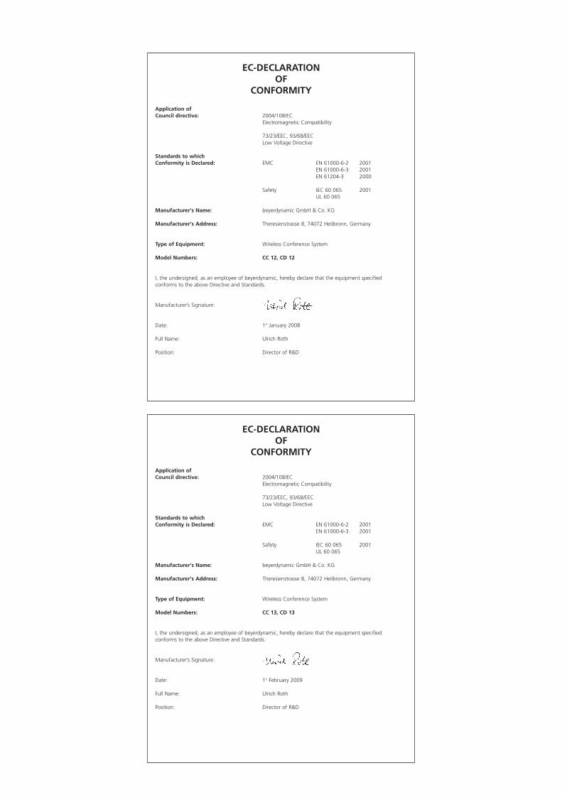
EC-DECLARATIONOF
CONFORMITY
Application ofCouncil directive: 2004/108/EC
Electromagnetic Compatibility
73/23/EEC, 93/68/EEC Low Voltage Directive
Standards to which Conformity is Declared: EMC EN 61000-6-2 2001
EN 61000-6-3 2001EN 61204-3 2000
Safety IEC 60 065 2001UL 60 065
Manufacturer's Name: beyerdynamic GmbH & Co. KG
Manufacturer's Address: Theresienstrasse 8, 74072 Heilbronn, Germany
Type of Equipment: Wireless Conference System
Model Numbers: CC 12, CD 12
I, the undersigned, as an employee of beyerdynamic, hereby declare that the equipment specified conforms to the above Directive and Standards.
Manufacturer’s Signature:
Date: 1st January 2008
Full Name: Ulrich Roth
Position: Director of R&D
EC-DECLARATIONOF
CONFORMITY
Application ofCouncil directive: 2004/108/EC
Electromagnetic Compatibility
73/23/EEC, 93/68/EEC Low Voltage Directive
Standards to which Conformity is Declared: EMC EN 61000-6-2 2001
EN 61000-6-3 2001
Safety IEC 60 065 2001UL 60 065
Manufacturer's Name: beyerdynamic GmbH & Co. KG
Manufacturer's Address: Theresienstrasse 8, 74072 Heilbronn, Germany
Type of Equipment: Wireless Conference System
Model Numbers: CC 13, CD 13
I, the undersigned, as an employee of beyerdynamic, hereby declare that the equipment specified conforms to the above Directive and Standards.
Manufacturer’s Signature:
Date: 1st February 2009
Full Name: Ulrich Roth
Position: Director of R&D

DEF
16/
BA M
CW
-D 5
0 (0
4.10
)/577
.022
/ •
Änd
erun
gen
und
Irrtü
mer
vor
beha
lten
• Su
bjec
t to
cha
nge
with
out
notic
e •
Suje
t à
chan
gem
ent
sans
pré
avis
• P
rinte
d in
Ger
man
y
beyerdynamic GmbH & Co. KGTheresienstr. 8 | 74072 Heilbronn – GermanyTel. +49 (0) 7131 / 617 - 0 | Fax +49 (0) 7131 / 617 - [email protected] | www.beyerdynamic.de
Weitere Vertriebspartner weltweit finden Sie unter www.beyerdynamic.deFor further distributors worldwide, please go to www.beyerdynamic.com