bearing class and select
DESCRIPTION
nnTRANSCRIPT

Chapter 2
Bearing Classification andSelection
2.1 Introduction
Design is a creative process aimed at finding a solution to a particular problem.In all forms of design a particular problem may have many different solutions,mainly because design requirements can be interpreted in many ways. Forexample, it may be desirable to produce:
* The cheapest design
* The easiest to build with available materials
* The most reliable
* The one that takes up the smallest space
* The one that is lightest in weight
* The best from any of a whole variety of possible standpoints
The task of the designer is therefore not clearcut, because he or she has to choosea reasonable compromise between these various requirements and then has todecide to adopt one of the possible designs that could meet this compromise.The process of bearing selection and design usually involves these steps:
1. Selecting a suitable type of bearing
2. Estimating a bearing size that is likely to be satisfactory
3. Analyzing bearing performance to see if it meets the requirements
4. Modifying the design and the dimensions until the performance is near towhichever optimum is considered the most important
23
Copyright © 2004 Marcel Dekker, Inc.

24 FUNDAMENTALS OF FLUID FILM LUBRICATION
The last two steps in the process can be handled fairly easily by someone whois trained in analytical methods and understands the fundamental principles ofthe subject. The first two steps, however, require some creative decisions tobe made and for many people represent the most difficult part of the designprocess.
2.2 Bearing Classification
A bearing is a support or guide that locates one machine component withrespect to others in such a way that prescribed relative motion can occur whilethe forces associated with machine operation are transmitted smoothly andefficiently. Bearings can be classified in several ways: according to the basicmode of operation (rubbing, hydrodynamic, hydrostatic, or rolling element),according to the direction and nature of the applied load (thrust or journal), oraccording to geometric form (tapered land, stepped parallel surface, or tiltingpad). There is much to be said for classification according to the basic modeof operation, with subdivisions to account for different geometric forms andloading conditions. That classification is used in this book.
2.2.1 Dry Rubbing Bearings
In dry rubbing bearings the two bearing surfaces rub together in rolling or slid-ing motion, or both, and are lubricated by boundary lubrication. Examples ofdry rubbing bearings are unlubricated journals made from materials such asnylon, polytetraftuoroethylene, and carbon and diamond pivots used in instru-ments. The load-carrying and frictional characteristics of this class of bearingscan be related directly to the basic contact properties of the bearing materials.
2.2.2 Impregnated bearings
In this type of bearing a porous material (usually metal) is impregnated with alubricant, thus giving a self-lubricating effect. The porous metal is usually madeby sintering (heating to create a coherent mass without melting) a compressedmetal powder (e.g., sintered iron or bronze). The pores serve as reservoirs forthe lubricant. The load-carrying and frictional characteristics of the bearingdepend on the properties of the solid matrix and the lubricant in conjunctionwith the opposing solid. The lubricant may be a liquid or a grease.
In general, the application of impregnated bearings is restricted to lowsliding speeds (usually less than 1 or 1.5 m/s), but they can carry high meanpressures (often up to 7 to 15 MPa). A great advantage of these bearings is thatthey are simple and cheap, just like rubbing bearings, and they are frequentlyused in low-speed or intermittent-motion situations such as automobile chassis,cams, and oscillating mechanisms.
Impregnated separators for small ball bearings such as those used in pre-cision instruments are sometimes used as lubricant reservoirs for the rolling
Copyright © 2004 Marcel Dekker, Inc.

BEARING CLASSIFICATION 25
elements when a minimum amount of lubricant is required. In this case theporous material is generally a plastic (e.g., nylon).
It is usually doubtful that the impregnated bearing operates in true hy-drodynamic fashion owing to the small amount of lubricant that is present.The behavior can be described as partial hydrodynamic lubrication, thereforeimplying partial lubrication. The bearing's hydrodynamic performance can beanalyzed by assuming that a full film exists in the clearance space and that thelubricant flow within the porous material is covered by Darcy's law as pointedout, for example, in Cameron (1976). Darcy's simple formula for porous bear-ings relates the pressure gradient to the How within a porous material whileneglecting inertia! effects and assuming that there is no relative surface veloc-ity. A simultaneous solution of the Reynolds equation and the flow equation fora porous matrix yields How patterns, pressure distributions, and load-carryingcapacities that can be used to construct design charts. Satisfactory designprocedures, however, usually embody a considerable amount of experimentalinformation and operating experience to supplement the hydrodynamic analy-sis. Difficulty in qualifying the separate actions that govern bearing behaviorreflects the partial hydrodynamic operation of many bearings in this class.
2.2.3 Conformal Fluid Film Bearings
The opposing surfaces of hydrodynamic Huid Him bearings are completely sep-arated by a lubricant Him. The lubricant may be a liquid or a gag, and theload-carrying capacity derived from the pressure within the lubricating Rimmay be generated by the motion of the machine elements (self-acting or hydro-dynamic bearings) or by external pressurization (hydrostatic) or hydrodynamicsqueeze motion, or by a combination of these actions. In all cases the frictionalcharacteristics of the bearings are governed by the laws of viscous How. Theload-carrying capacities are similarly dictated by hydrodynamic action, but theproperties of the bearing materials have to be considered (e.g., the fatigue lifeor low friction properties) at extremely low speeds.
The methods of feeding lubricant to a conformal Huid Him bearing varyconsiderably. At low speeds and modest loads a simple ring-oiler that draws oilup to the bearing from a reservoir by means of viscous lifting might suffice, butin many modern machines the oil is supplied to the bearing under pressure toensure adequate HHing of the clearance space. Externally pressurized, or hydro-static, bearings require elaborate lubricant supply systems, and the lubricantenters the bearing under a pressure of the order of a megapascal. This type ofbearing is particularly useful at high loads and low speeds or when Him stiffnessperpendicular to surface motion is important.
A simple subdivision of conformal Huid Him bearings that accounts for thenature of the lubricant, the mode of operation, the direction of motion, thenature of the load, and the geometric form of the bearing is shown in Fig. 2.1.
Copyright © 2004 Marcel Dekker, Inc.

26 FUNDAMENTALS OF FLUID FILM LUBRICATION
Conforms! fluid film bearings
Nature oflubrication
Liquid
Mode of operation HydrodynamicI
Direction of load JournalI
I ISqueeze Hydrostatic
! I
Combined
Gas
Hybrid_J
ThrustI
Nature of load
Geometric form(e.g. partial orcomplete journalbearings)
SteadyI
Geometric form
DynamicI
Figure 2.1: Divisions of conforma! fluid film bearings.
Copyright © 2004 Marcel Dekker, Inc.
BEARING CLASSIFICATION 27
Rolling-element bearings
Nature oflubrication
rOilL
Grease]
rMode of operation Ball
Roller(includingneedle)
Direction of load Thrust Angular. contact .
Nature of load
Geometric form
Steady
[_
Dynamic
!
Single row Double row
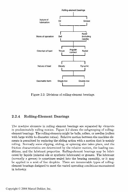
Figure 2.2: Divisions of rolling-element bearings.
2.2.4 Rolling-Element Bearings
The machine elements in rolling element bearings are separated by elementsin predominately rolling motion. Figure 2.2 shows the subgrouping of rolling-element bearings. The rolling elements might be balls, rollers, or needles (rollerswith large width-to-diameter ratios). Relative motion between the machine ele-ments is permitted by replacing the sliding action with a motion that is mainlyrolling. Normally some slipping, sliding, or spinning also takes place, and thefriction characteristics are determined by the relative motion, the loading con-ditions, and the lubricant properties. Rolling-element bearings may be lubri-cated by liquids (mineral oils or synthetic lubricants) or greases. The lubricant(normally a grease) is sometimes sealed into the bearing assembly, or it maybe applied in a mist of fine droplets. There are innumerable types of rolling-element bearings designed to meet the varied operating conditions encounteredin industry.
Copyright © 2004 Marcel Dekker, Inc.

28 FUNDAMENTALS OF FLUID FILM LUBRICATION
2.3 Bearing Selection
The designer is often confronted with decisions on whether a rolling-element orhydrodynamic bearing should be used in a particular application. The follow-ing characteristics make rolling-element bearings more desirable than hydrody-namic (conformal Quid Aim) bearings in many situations: (1) low starting andgood operating friction, (2) the ability to support combined radial and thrustloads, (3) less sensitivity to interruptions in lubrication, (4) no self-excited in-stabilities, (5) good low-temperature starting, and (6) the ability to seal thelubricant within the bearing. Within reasonable limits, changes in load, speed,and operating temperature have but little effect on the satisfactory performanceof rolling-element bearings.
The following characteristics make rolling-element bearings less desirablethan hydrodynamic (conformal fluid film) bearings: (1) Unite fatigue life sub-ject to wide fluctuations, (2) larger space required in the radial direction, (3)low damping capacity, (4) higher noise level, (5) more severe alignment re-quirements, and (6) higher cost. Each type of bearing has its particular strongpoints, and care should be taken in choosing the most appropriate type of bear-ing for a given application. Useful guidance on the important issue of bearingselection has been presented by the Engineering Sciences Data Unit (ESDU).The ESDU documents (1965, 1967) are excellent guides to selecting the type ofjournal or thrust bearing that is most likely to give the required performancewhen considering the load, speed, and geometry of the bearing.
Figure 2.3, reproduced from ESDU (1965), shows the typical maximumload that can be carried at various speed, for a nominal life of 10,000 h at roomtemperature, by various types of journal bearings on shafts of the diametersquoted. The heavy curves indicate the preferred type of journal bearing for aparticular load, speed, and diameter and thus divide the graph into distinctiveregions. The applied load and speed are usually known, and this enables apreliminary assessment to be made of the type of journal bearing most likelyto be suitable for a particular application. In many cases the shaft diameterwill already have been determined by other considerations, and Fig. 2.3 can beused to find the type of journal bearing that will give adequate load-carryingcapacity at the required speed.
These curves are based on good engineering practice and commerciallyavailable parts. Higher loads and speeds or smaller shaft diameters are pos-sible with exceptionally high engineering standards or specially produced ma-terials. Except for rolling-element bearings the curves are drawn for bearingswith widths equal to their diameters. A medium-viscosity mineral oil lubricantis assumed for the hydrodynamic bearings.
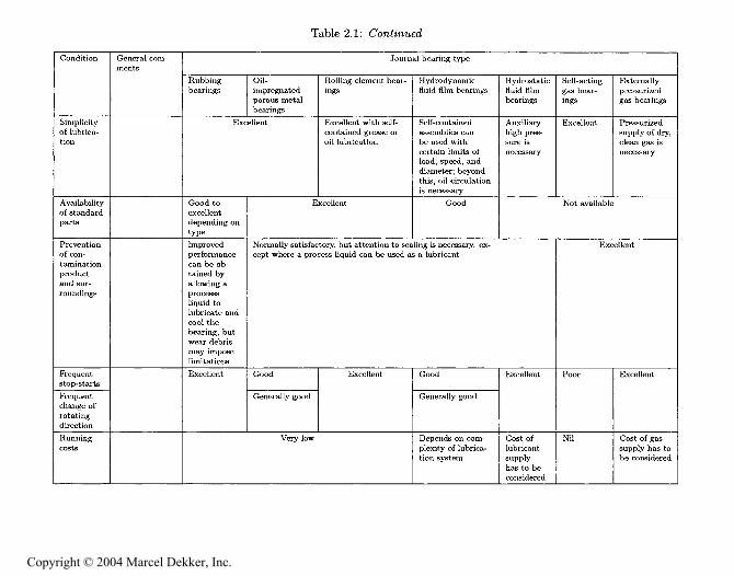
Considerations other than the load and speed may often have an overridingimportance in bearing selection. Table 2.1 gives the advantages and limitationsof various bearings in relation to environmental conditions and particular re-quirements. It is emphasized that Fig. 2.3 and Table 2.1 are only intended asguides.
Copyright © 2004 Marcel Dekker, Inc.

BEARING SELECTION 29
10'
10'
5 10"=- z
10
— Rubbing bearingsOil-impregnated porous metal bearingsRotling-element bearingsHydrodynamic oi! film bearings
10'
*§S 10*
L ^10'
10
Shaftdiameter,m (in.)0.5 (20).'
y L'<3
\ - ApproximateV* solid-steel-shaft
burst limit
Approximate maximumspeed, rubbing beari--
— Approximate maximumE speed, rolling-element bearings
10'-
.0125(7?)
I , I ,!,hl ! i I i l i l I I I I i l i l I I I I i t i l I I I I i l i l I l ; l i l l ! I I10-' 1 10
Frequency of rotation, rps10 10* 2x10*
I I , l , l , l , l I , l.l.hl I < l . l . h l I i hl.li! I < ! ; l < ! i l I . I . h i . I1 10 10 1Q3 10* 10 10
Frequency of rotation, rpm
Figure 2.3: General guide to journal bearing type. Except for rolling-element
bearings, curves are drawn for bearings with width equal to diameter. A
medium-viscosity mineral oil is assumed for hydrodynamic bearings. [.From
Copyright © 2004 Marcel Dekker, Inc.

30FUNDAMENTALS OF FLUID FILM LUBRICATION
Q[B
'g
^ 'S 3
gg"
S^
^ &'g'
&a
s -ih
g g." 'S -
o'.H
=
<c 3
s= 5-
.S '
^ =
Copyright © 2004 Marcel Dekker, Inc.
BEARING SELECTION
31
*ee
T'glS ^
'
^ ^1
!L
.g-g
n.a .a .a-
g- e
Copyright © 2004 Marcel Dekker, Inc.

Table 2.1: Conceded
Wetness
ity
Radiation
Low start-ing torque
nn que
radial loca-tion
Life
Combinationof axial andload-carrying
Silent run-ning
General corn-
Attention to
necessary
Journal bearing type
Rubbing
Normally
material
Satisfactory
Not normallyrecom-
Poor
Oil-
porous metalbearings
Normally satis-
belring "
Normally satisfac-
attention to scalingmay be necessary
Hydrodynamic Hydrostaticfluid Him
Satisfactory
Lubricant may impose limitations
Satisfactory Good Satisfactory
Good
Finite but predictable
A thrust force must be provided
Good forsteady
Excellent
Most types capable of
Usually satisfactory;consult manufacturer
Theoretically infl-
Excellent
Excellent
Theoreticallyinfinite
Self-acting
ings
Externally
gas bearings
Satisfactory
Excellent
Satisfactory
Good
Theoretically
and num-
and starts
Excellent
Excellent
Theoretically
A thrust force must be provided to carry the axial loads
Excellent Excellentexcept forpossible
Excellent Excellentexcept for
noise
o>MZ
O"9
trCO
3rgtr"G3
o
Copyright © 2004 Marcel Dekker, Inc.

Table 2.2: Advantages and limitations of thrust bearings. [From ESDU (1967).]
Condition
High tem-perature
Low tem-perature
Externatvibration
Space re-quirements
Dirt or dust
Vacuum
Genera! com-ments
Attention todifferentia]expansions andtheir effect
upon axiat
clearance is
necessary
Attention to
differentia!expansionsand starting
torques isnecessary
Attention to
the possibility
of fretting
essary (exceptfor hydrostaticbearings)
Thrust bearing type
Rubbingbearings
Normallysatisfactorydepending on
material
Oil-impregnatedporous metalbearings
Attention
to oxidation
resistanceof lubricant
necessary
Lubricant may
impose limita-tions; consider-
ation of start-
ing torque isnecessary
Normally satisfactory exceptwhen peak of impact load ex-ceeds load carrying capacity
Small radial extent
mg Uaget ' ''
Excellent
Rolling-element bear-ings
Up to 100 °C nolimitations; from 100to 250 °C stabilized
bearings and speciallubrication proce-dures are probablyrequired
Below -30 °C spe-
cial lubricants are re-
quired; considerationof starting torque is
necessary
May impose limita-tions; consult manu-
facturer
Bearings of many dif-ferent proportions areavailable
Sealing is important
HydrodynamicHuid film bearings
HydrostaticHuid Himbearings
Attention to oxidation resis-
tance of lubricant is necessary
Lubricant mayimpose limitations;
consideration ofstarting torque is
necessary
Satisfactory
Lubricant
may im-
pose limita-
tions
Excellent
Small radial extent but total
space requirement depends onthe lubrication feed system
t rtanf'°"°""'"
Lubricant may impose limitations
Self-acting
gas bear-
ings
Externally
pressurizedgas bearings
Excellent
Excellent; thorough dry-ing of gas is necessary
Normally
satisfactory
Smallradial
extent
p.r "*
Not nor-mally
Excellent
Small radialtotal space
requirementdepends on
gas feedsystem
Satisfactory
Not appli-
cable when
has to be
maintained
r*MO
O
Copyright © 2004 Marcel Dekker, Inc.

34FUNDAMENTALS OF FLUID FILM LUBRICATION
S g
H S & 8
H S
&. n.
E -o
°3.6
0
= " -5 "3
E.2:
A^
< S
S So s
o -3 'c
UoJ2
Copyright © 2004 Marcel Dekker, Inc.

BEARING SELECTION
35
^V2
M.S
. a. t
s.§ s
ypesEL,
m
ig^o^
a g0 -S
>, >,
o 8 §
,c o -n
ss.g'o 'o
Sa a 3
0 O M
'33-3^
Copyright © 2004 Marcel Dekker, Inc.

36 FUNDAMENTALS OF FLUID FILM LUBRICATION
10=
S 10"
E
E
10
10"
-9 10"
10
***** Rubbing bearingsOil-impregnated porous metal bearingsRolling-element bearingsHydrodynamic oil film bearings
Diameter,m (in.)0.5(20) ,
. — — —\ ^ - Approximate bursting" ^ speed, steel disks
.25(10)
Approximate maximumspeed, rubbing bearings-
-Approximate maximumspeed, rolling-elementbearings
J-L ! i h l1 10 10'Frequency of rotation, rps
10* 2x10"
I I . l . l i h l I i l i h l i l I . 1 . 1 . I . I I . l . h l i l I . [.I.hi I . 1 . 1 . ! < l1 10 10 1C? 1? 10 10
Frequency of rotation, rpm
Figure 2.4: General guide to thrust bearing type. Except for roHing-elementbearings, curves are drawn for typical ratios of inside diameter to outside di-ameter. A medium-viscosity mineral oil is assumed for hydrodynamic bearings.
Copyright © 2004 Marcel Dekker, Inc.

CLOSURE 37
Similarly, Fig. 2.4, reproduced from ESDU (1967), shows the typical max-imum load that can be carried at various speeds, for a nominal life of 10,000 hat room temperature, by various types of thrust bearings on shafts of the di-ameters quoted. The heavy curves again indicate the preferred type of bearingfor a particular load, speed, and diameter and thus divide the graph into majorregions. Considerations other than load and speed are given in Table 2.2 forthrust bearings.
2.4 Closure
This chapter began with a general discussion of the process of bearing design.The four primary steps used in bearing design are selecting a suitable type,estimating bearing size, analyzing performance, and modifying or fine-tuning.It was pointed out that the first two steps are the most difficult and requirecreative decisions, whereas the last two steps can be handled fairly easily bya person trained in analytical methods. After considering several options, itwas decided that bearings would best be classified by considering their modesof operation. The four primary classes of bearing that were considered weredry or rubbing bearings, which use boundary lubrication if any; impregnatedbearings, which use partial lubrication; rolling-element bearings, which use elas-tohydrodynamic lubrication; and hydrodynamic fluid film bearings, which usehydrodynamic lubrication. The Engineering Sciences Data Unit documents canbe used as guides in selecting the type of journal or thrust bearing most likely togive the required performance when considering its load, speed, and geometry.Considerations other than load and speed are important in bearing selection.Thus, tables are presented that give the advantages and limitations of variousbearings in relation to environmental conditions and particular requirements.It should be recognized that information on bearing selections given in thischapter is intended to be a guide to selecting a suitable type of bearing and toestimating a bearing size that is likely to be satisfactory.
2.5 Problems
2.1 Figures 2.3 and 2.4 show the relationship between load and speed for fourdifferent types of bearings. How would you use these figures to help youselect the appropriate bearing for your particular application?
2.2 Suggest suitable types of bearing to meet the following situations: (a)High load, very low speed, very low friction; (b) Light load, very highspeed, no liquid lubricant; (c) Light load, low speed, no liquid lubricant.
2.3 Explain why gas-lubricated bearings are appealing. Describe the limitingfeatures of this type of bearing.
Copyright © 2004 Marcel Dekker, Inc.
38 FUNDAMENTALS OF FLUID FILM LUBRICATION
References
Cameron, A. (1976): .Ba3M LM&WcaMort T/teory, 2d ed. Ellis Horwood Limited,Chichester, England.
Engineering Sciences Data Unit (ESDU) (1965): General Guide to the Choiceof Journal Bearing Type. Item 65007, Institution of Mechanical Engineers,London.
Engineering Sciences Data Unit (ESDU) (1967): General Guide to the Choiceof Thrust Bearing Type. Item 67033, Institution of Mechanical Engineers,London.
Copyright © 2004 Marcel Dekker, Inc.