beamforming in 3g and 4g mobile communications: the ...cdn.intechweb.org/pdfs/24910.pdf · 0...
TRANSCRIPT

0
Beamforming in 3G and 4G MobileCommunications: The Switched-Beam Approach
Konstantinos A. Gotsis1 and John N. Sahalos2
1Aristotle University of Thessaloniki2University of Nicosia
1Greece2Cyprus
1. Introduction
The technology and deployment of modern mobile communications systems, should adaptto the continuous and rapid growth of wireless data traffic. Besides the increase inbandwidth, the addition of cell sites and sectors, and the enhancement of air interfacecapabilities, smart antennas play also a substantial role in the improvement of wirelesssystems’ performance. When we refer to smart antennas, we mean structures of multipleantenna elements at the transmitting and/or the receiving side of the radio link, whose signalsare properly processed, in order to better exploit the mobile radio channel and enhance thecommunications performance. During the last decade there has been intensive research onMultiple Input-Multiple Output (MIMO) systems, which are antenna formations that involveprocessing at both sides of the link (Jensen & Wallace, 2004).Depending on the signal processing methods and the adaptive schemes used, smart antennatechniques can be separated into three broad categories: a) Diversity, b) Spatial Multiplexing(SM), and c) Beamforming. Roughly speaking, beamforming aims at improving Signalto Interference plus Noise Ratio (SINR), diversity aims at reducing the variations in theSINR experienced by the receiver, while SM aims at sharing SINR in high SINR scenarios(3G-Americas, 2009).Transmit and receive diversity are used in order to mitigate the problem of multipath fading,enhancing the reliability of a wireless link. In SM, which is the most popular transmissionscheme of MIMO systems, multiple data streams are transmitted in parallel, increasing thedata transmission rate. Beamforming uses an antenna array1 to transmit/receive energy ina specific direction, increasing the cellular capacity and coverage. Although it is an earlysmart antenna technology, beamforming is still supported by the latest 3GPP releases (3rdGeneration Partnership Project - www.3gpp.org), namely the LTE (Long Term Evolution)and LTE advanced. Operators though seem reluctant to incorporate smart beamformingtechniques into base stations, mainly due to the cost and complexity of such implementations.The current research concerning 4G mobile systems is mostly concentrated on MIMOprocessing and space-time coding algorithms. However, antenna arrays and beamforminghave still the potential to contribute in the enhancement of modern cellular systems.
1 Antenna array is called the aggregation of radiating elements in a certain electrical and geometricalarrangement (Balanis, 2005).
11
www.intechopen.com

2 Will-be-set-by-IN-TECH
Beamforming systems are generally classified as either Switched-Beam Systems (SBS) orAdaptive Array Systems (AAS). A SBS relies on a fixed BeamForming Network (BFN) thatproduces a set of predefined beams. Probably the most popular solution for fixed BFNis a Butler Matrix (BM) (Butler & Lowe, 1961). A BM in its standard form is a M × Mnetwork, which consists of hybrid couplers, phase shifters and crossovers. M is the number ofinput/output ports that give a set of M different beams. In (Kaifas & Sahalos, 2006), the readercan find a comprehensive review of the BM functionality and its implementation issues.A SBS needs a Switching Network (SN) in order to select the appropriate beam to receive thesignal from a particular Mobile Station (MS). As it is shown in Fig. 1a, the maximum of theselected beam might not point at the desired direction. Moreover, typically a beam servesmore than one MS. On the contrary, an AAS has the possibility to form a special beam foreach user Fig. 1b. This is accomplished by a series of adaptive array processors that applyweight vectors to the received and transmitted signals, in order to control the relative phasebetween the antenna elements and their amplitude distribution. In this way specific beampatterns can be produced, directing the main lobe towards the desired MS and nulls towardsthe interfering signals. Thus, Direction of Arrival (DoA) estimation of signals impinging onan antenna array is a very important issue for cellular communications.
Fig. 1. Beam coverage of a) switched-beam system and b) adaptive array system.
Adaptive beamforming presupposes that the Base Station (BS) updates the localization of theMS. However, accurate localization is not an easy task, since a big number of simultaneousmobile users can overload the process. Therefore, although many popular DoA estimationmethods and adaptive beamforming algorithms have been developed (Godara, 2004), noparticular standardization has been established. The implementation of an adaptive system ismuch more complex than a switched-beam one. On the other hand, ideal adaptive beampointing minimizes the interference between users and exploits much better the availablepower resources. In any case there are advantages and disadvantages which have to beconsidered (Baumgartner, 2003; Baumgartner & Bonek, 2006; Osseiran et al., 2001; Pedersenet al., 2003).In order to exploit the simplicity of SBS, and promote effective smart antenna beamforming,the authors in (Gotsis et al., 2009) developed a Neural Network (NN) DoA estimationmethodology, which has been especially designed for an SBS and applied to a Direct SequenceCode Division Multiple Access (DS-CDMA) scheme. As a succession of the above paper, animproved BM based beamforming network has been presented in (Gotsis et al., 2010). Theproposed structure provides enhanced beamforming flexibility compared to a typical BMand also has the possibility to efficiently work in conjunction with the NN-DoA estimationtechnique.The main scope of this chapter is the completion and extension of the work presented inthe above references. A basic subject is the introduction of ’DoA-based Switching (DoAS)’
202 Recent Developments in Mobile Communications – A Multidisciplinary Approach
www.intechopen.com

Beamforming in 3G and 4G Mobile Communications: The Switched-Beam Approach 3
and its incorporation into a 3G mobile communications framework, like the Universal MobileTelecommunications System (UMTS). DoAS is evaluated and compared to the so called in thiswork ’Typical Switching (TS)’. The term ’TS’ refers to the typical operation of a SBS, which isdetermined by the highest uplink SINR or by the highest mean received power.In (3G-Americas, 2009; 2010) one can find various propositions for 4G systems that combineMIMO techniques and fixed beamforming (using BM) into a single structure. Generally, BMstill attracts the interest of researchers (Chia-Chan et al., 2010; Peng et al., 2009). Therefore, the3G case is followed by a discussion of how the switched-beam approach using BM could beuseful in the context of next generation systems.
2. The improved switched-beam system
Fig. 2. a) Typical schematic of a Butler Matrix (BM) 8 × 8 and its SN. b) Schematic of abeamforming network with a typical BM 8 × 8 enhanced by the appropriate SN and a groupof SLPS.
2.1 The beamforming network
A concentrated illustration of the beamforming network proposed in (Gotsis et al., 2010), isdepicted in Fig. 2b. In Fig. 2a, a typical schematic of a BM 8 × 8 and its SN is shown.The BFN is constituted of three main blocks: a) a BM 8 × 8, b) a switching network and c)a block of Switched Line Phase Shifters (SLPS). Regarding the BM, taking into account theradiation pattern characteristics, the degrees of freedom offered and the complexity of theimplementation, the 8 × 8 dimensions are the most appropriate to cover an angular sector of120◦.
2.1.1 Single and combined BM port excitation
The SN consists of a circuit of Single Pole Double Throw (SPDT) switches (Pozar, 1990) indendroid structure and a 3dB power divider. A digital word determines the switches’ state (’0’
203Beamforming in 3G and 4G Mobile Communications: The Switched-Beam Approach
www.intechopen.com
4 Will-be-set-by-IN-TECH
30 40 50 60 70 80 90 100 110 120 130 140 150−40
−30
−20
−10
0
angle (deg.)
dB
1R4L3R1L2L2R3L4R
(a)
30 40 50 60 70 80 90 100 110 120 130 140 150−40
−35
−30
−25
−20
−15
−10
−5
0
angle (deg.)
dB
1R+2R3R+4R1L+2L1L+1R3L+4L2R+3R2L+3L
(b)
30 40 50 60 70 80 90 100 110 120 130 140 150−40
−35
−30
−25
−20
−15
−10
−5
0
angle (deg.)
dB
(c)
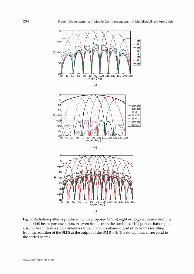
Fig. 3. Radiation patterns produced by the proposed SBS: a) eight orthogonal beams from thesingle (1:0) beam port excitation, b) seven beams from the combined (1:1) port excitation plusa sector beam from a single antenna element, and c) enhanced grid of 15 beams resultingfrom the addition of the SLPS at the output of the BM 8 × 8. The dotted lines correspond tothe added beams.
204 Recent Developments in Mobile Communications – A Multidisciplinary Approach
www.intechopen.com

Beamforming in 3G and 4G Mobile Communications: The Switched-Beam Approach 5
or ’1’) and thus, the signal’s route through the network. The first bit of the word correspondsto the state of the main switch (S1), which gives two options. The first option is the typicalsingle port excitation (1:0) of the BM, that leads to the uniform illumination of the antennaelements. The result is a grid of eight orthogonal beams, as shown in Fig. 3a. The beams arecalled orthogonal in the sense that at one beam’s maximum, all the other beam patterns havea minimum. There are four beams at the right (R) and four at the left (L) of the broadside.The beam ports take their name after the position of the corresponding beam in relation tothe broadside. The second option is the combined equal excitation (1:1) of the BM portsthat correspond to pairs of adjacent in space orthogonal beams. This results to the cosineillumination of the antenna elements and a grid of seven beams, as shown in Fig. 3b. In thesame diagram the sector beam of a single antenna element (a rectangular microstrip patch)is also illustrated. The reader observes that 1:1 provides beams with lower Side Lobe Level(SLL), higher Crossover Level (CL) and wider Half-Power BeamWidth (HPBW) than the 1:0case. This is due to the cosine versus the uniform illumination of the antenna elements, thatconfirms the following rule of thumb: "in linear antenna array synthesis the array with thesmoothest amplitude distribution has the smallest side lobes and the larger HPBW (and viceversa)" (Balanis, 2005). Details about the characteristics of the discussed radiation patterns in(Gotsis et al., 2009).
2.1.2 Extra beams from single port excitation
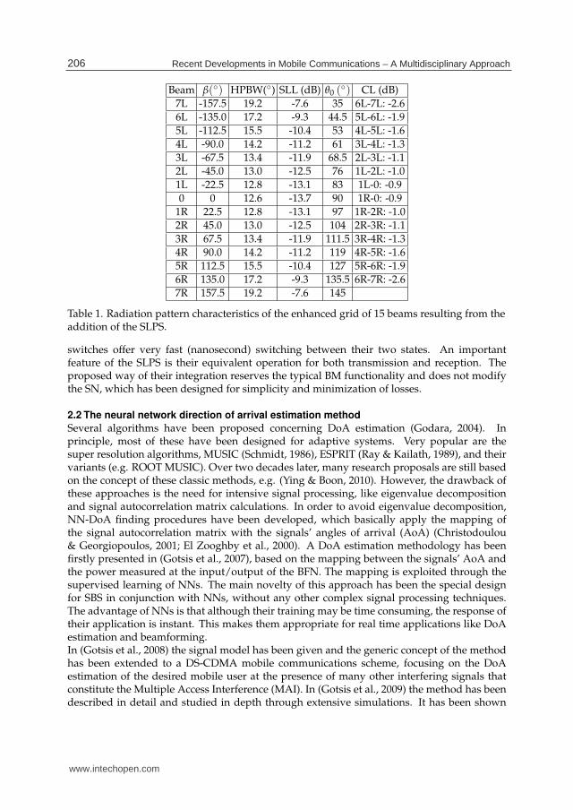
Extra beams in a BM can be produced if a block of SLPS is added at its output (see Fig. 2).The SLPS do not modify the layout of the typical BM. They just interconnect the last row ofthe hybrids and the antenna ports of the BM. A SLPS is a simple structure, which uses twoSPDT switches to drive the signal between the one of two microstrip lines of different length(Pozar, 1990). The length difference determines the phase difference between the two paths.The one path (solid reference line) of the proposed structure, is the path of the typical BMthat gives the orthogonal beams. The length of the other line (dotted in Fig. 2b), has beenchosen so that an extra phase Δφ = (n − 1) · 22.5◦ is added at the nth antenna element2. Thus,the progressive phase difference produced by the excitation of each beam port is increasedby 22.5◦. For example the beam port 1R produces either the predefined phase difference β =22.5◦ or β = 45◦. The new phase difference corresponds to a new beam that lies between 1Rand 2R. All possible single port excitations create an enhanced grid of 15 beams. This grid isconstituted from the standard eight orthogonal beams, plus the seven beams (also orthogonalbetween them) that come from the use of the added SLPS (Fig. 3c). Table 1 summarizes thefeatures of the resulting pattern.Compared to Fig. 3a the CL is much higher. Even between the edge beams, the CL is higherthan -3dB. Between the rest of the beams the CL ranges from -1.9dB to -0.9dB, whereas in thetypical eight beams pattern ranges from -4.7dB to -3.8dB (Gotsis et al., 2009). This meansthat anywhere in the 120◦ sector a MS can be served by nearly the maximum of one ofthe main lobes, which has the narrowest possible HPBW. For example the 1:0 beam withmaximum at θ0 = 61◦ has HPBW = 14.2◦, while the 1:1 beam with maximum at θ0 = 62◦
has HPBW = 18.5◦. The 1:0 excitations give narrower beamwidths than all the possiblecorresponding combined excitations 1 : x, where 0 < x < 1. On the other hand, the 1:0beams have the highest SLL.Besides producing the desired radiation patterns, the SLPS addition is practical and easy toimplement. Their integration in a single layer microstrip structure is simple and the SPDT
2 It should be noted that for the 1st element there is no phase shifter, since its phase is taken as a reference.
205Beamforming in 3G and 4G Mobile Communications: The Switched-Beam Approach
www.intechopen.com
6 Will-be-set-by-IN-TECH
Beam β(◦) HPBW(◦) SLL (dB) θ0 (◦) CL (dB)
7L -157.5 19.2 -7.6 35 6L-7L: -2.6
6L -135.0 17.2 -9.3 44.5 5L-6L: -1.9
5L -112.5 15.5 -10.4 53 4L-5L: -1.6
4L -90.0 14.2 -11.2 61 3L-4L: -1.3
3L -67.5 13.4 -11.9 68.5 2L-3L: -1.1
2L -45.0 13.0 -12.5 76 1L-2L: -1.0
1L -22.5 12.8 -13.1 83 1L-0: -0.9
0 0 12.6 -13.7 90 1R-0: -0.9
1R 22.5 12.8 -13.1 97 1R-2R: -1.0
2R 45.0 13.0 -12.5 104 2R-3R: -1.1
3R 67.5 13.4 -11.9 111.5 3R-4R: -1.3
4R 90.0 14.2 -11.2 119 4R-5R: -1.6
5R 112.5 15.5 -10.4 127 5R-6R: -1.9
6R 135.0 17.2 -9.3 135.5 6R-7R: -2.6
7R 157.5 19.2 -7.6 145
Table 1. Radiation pattern characteristics of the enhanced grid of 15 beams resulting from theaddition of the SLPS.
switches offer very fast (nanosecond) switching between their two states. An importantfeature of the SLPS is their equivalent operation for both transmission and reception. Theproposed way of their integration reserves the typical BM functionality and does not modifythe SN, which has been designed for simplicity and minimization of losses.
2.2 The neural network direction of arrival estimation method
Several algorithms have been proposed concerning DoA estimation (Godara, 2004). Inprinciple, most of these have been designed for adaptive systems. Very popular are thesuper resolution algorithms, MUSIC (Schmidt, 1986), ESPRIT (Ray & Kailath, 1989), and theirvariants (e.g. ROOT MUSIC). Over two decades later, many research proposals are still basedon the concept of these classic methods, e.g. (Ying & Boon, 2010). However, the drawback ofthese approaches is the need for intensive signal processing, like eigenvalue decompositionand signal autocorrelation matrix calculations. In order to avoid eigenvalue decomposition,NN-DoA finding procedures have been developed, which basically apply the mapping ofthe signal autocorrelation matrix with the signals’ angles of arrival (AoA) (Christodoulou& Georgiopoulos, 2001; El Zooghby et al., 2000). A DoA estimation methodology has beenfirstly presented in (Gotsis et al., 2007), based on the mapping between the signals’ AoA andthe power measured at the input/output of the BFN. The mapping is exploited through thesupervised learning of NNs. The main novelty of this approach has been the special designfor SBS in conjunction with NNs, without any other complex signal processing techniques.The advantage of NNs is that although their training may be time consuming, the response oftheir application is instant. This makes them appropriate for real time applications like DoAestimation and beamforming.In (Gotsis et al., 2008) the signal model has been given and the generic concept of the methodhas been extended to a DS-CDMA mobile communications scheme, focusing on the DoAestimation of the desired mobile user at the presence of many other interfering signals thatconstitute the Multiple Access Interference (MAI). In (Gotsis et al., 2009) the method has beendescribed in detail and studied in depth through extensive simulations. It has been shown
206 Recent Developments in Mobile Communications – A Multidisciplinary Approach
www.intechopen.com

Beamforming in 3G and 4G Mobile Communications: The Switched-Beam Approach 7
that the desired signal’s DoA can be extracted with a less than one degree Root Mean SquareError (RMSE), even if its power level is 6dB less than each one of 39 interfering signals. A basicconclusion was that the 1:1 excitation of the BM should be used for the uplink communicationbetween the MS and the base station. Due to the non-orthogonality and the high CL of theseven beams pattern, the 1:1 mode gives much better DoA estimation results than the typical1:0. The orthogonality and higher directivity of the eight beams pattern are better for thedownlink transmission towards the desired MS. That is why the SN of the SBS has beendesigned to support both excitation modes.In the next section various beamforming possibilities involving the proposed SBS and theNN-DoA estimation method are presented and evaluated in terms of their performance in theframework of UMTS.
3. Smart switched beamforming in UMTS
UMTS has been standardized by the 3rd Generation Partnership Project (3GPP), which hasbeen a collaboration of various telecommunications associations from Europe, Japan, Korea,USA and China. The original scope of 3GPP was to produce technical specifications andtechnical reports for a 3G and beyond mobile system. Release 99 was the first release of3G specifications and it was essentially a consolidation of the underlying Global Systemfor Mobile Communications (GSM) and the development of the new Universal TerrestrialRadio Access Network (UTRAN). There have been many steps till 3GPP reached the LongTerm Evolution (LTE), which is a pre-4G standard, one step behind the LTE Advanced thatfully complies with the IMT-Advanced (International Mobile Telecommunications Advanced)requirements for 4G standards (www.3gpp.org).
3.1 Beam switching modes
Base station beamforming for UMTS has followed the general classification described in theintroduction. Particularly, UMTS Release 6 (3GPP, 2004) specified three possible modes:"none", "flexible beamforming", and "grid of fixed beams". The "none" mode signifies thatbeamforming is optional. "Flexible beamforming" corresponds to the adaptive beamformingused by an AAS, whereas the "grid of fixed beams" corresponds to a set of predefined beamsused by a SBS. As it was mentioned in the introduction, the SBS may operate either in the TSor the DoAS mode.
3.1.1 Typical Switching (TS)
In (3GPP, 2004) it has been specified that the operation of a SBS depends on the so called ’bestcell portion measurement’, which corresponds to the TS operation mode. A cell portion hasbeen "the part of a cell that is covered by a specific beam antenna radiation pattern, whichcan be created using a grid of fixed beam directions". In this context a cell is a "logicalcell", which is the area covered by the Primary Common Pilot Channel (P-CPICH) (Pedersenet al., 2003). When a call is initiated, the User Equipment (UE)3 is being accepted by thebeam that measures the highest SINR for the Physical Random Access Channel (PRACH).During the communication the switching is activated depending on the SINR measurementfor the Dedicated Physical Control Channel (DPCCH) and it is reported to the Radio NetworkController (RNC). The difference between common and dedicated channels is that in the firstcase the channels’ resources are shared to all or a group of cell users, whereas in the second
3 In UMTS terminology the mobile station is called User Equipment and the base station Node-B.
207Beamforming in 3G and 4G Mobile Communications: The Switched-Beam Approach
www.intechopen.com
8 Will-be-set-by-IN-TECH
case the channels are dedicated, through a particular code and frequency, to only one user. TheRNC which is the governing element in UTRAN and controls the Node-Bs that are connectedto it, decides for the best downlink beam. When a user leaves the coverage region of a fixedbeam and enters another beam region of the same cell, the UE should get informed about thischange. The information is done by the Radio Resource Control (RRC) messages, like the RRCphysical channel reconfiguration message (3GPP, 2008). The detailed description of UMTScommunication channels and their role in beamforming is out of the scope of this chapter;these can be found in the literature (Baumgartner, 2003; Holma & Toskala, 2007; Pedersenet al., 2003). Basic procedures are roughly given in order to frame our study.
3.1.2 DoA-based Switching (DoAS)
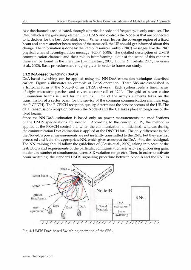
DoA-based switching can be applied using the NN-DoA estimation technique describedearlier. Figure 4 illustrates an example of DoAS operation. Three SBS are established ina trihedral form at the Node-B of an UTRA network. Each system feeds a linear arrayof eight microstrip patches and covers a sector-cell of 120◦. The grid of seven cosineillumination beams is used for the uplink. One of the array’s elements takes on thetransmission of a sector beam for the service of the common communication channels (e.g.the P-CPICH). The P-CPICH reception quality, determines the service sectors of the UE. Thedata transmission/reception between the Node-B and the UE takes place through one of thefixed beams.Since the NN-DoA estimation is based only on power measurements, no modificationsof the UMTS specifications are needed. According to the concept of TS, the method isapplied at the PRACH control bits when the communication is initialized, whereas duringthe communication DoA estimation is applied at the DPCCH bits. The only difference is thatthe Node-B’s power measurements are not instantly transmitted to the RNC, but they are firstprocessed and fed to the appropriate NN, which gives as output the DoA of the desired signal.The NN training should follow the guidelines of (Gotsis et al., 2009), taking into account therestrictions and requirements of the particular communication scenario (e.g. processing gain,maximum number of simultaneous users, SIR variation range etc). Then, in order to activatebeam switching, the standard UMTS signalling procedure between Node-B and the RNC is
Fig. 4. UMTS DoA-based Switching operation of the SBS .
208 Recent Developments in Mobile Communications – A Multidisciplinary Approach
www.intechopen.com

Beamforming in 3G and 4G Mobile Communications: The Switched-Beam Approach 9
realized. However, the "best cell portion measurement" is not determined by the highestSINR, but by the estimated actual DoA of the signal. The choice of the downlink beam isbased on the uplink DoA estimation, which is a realistic approach that is used in wirelesscommunications. This has been shown experimentally for the communication between a BSwith an eight element linear antenna array and a single element MS (Pedersen et al., 1999).
3.2 Performance of TS and DoAS
Depending on the switches’ state, the proposed SBS (Fig. 2b) supports various switched-beamconfigurations. The simplest one is the typical use of the eight orthogonal beams (1:0) for boththe Up and Down (UD) link. This configuration should work in the TS mode and is called’8UD’. An advanced choice for the TS mode, which is a proposition of this work, is the useof fifteen beams (1:0) for both the uplink and downlink (i.e. ’15UD’ configuration). Finally, anovel structure called ’7U15D’, works in the DoAS mode using the seven beams (1:1) for theuplink and the fifteen beams (1:0) for the downlink. A simulation model has been developedin order to perform a comparison between 15UD and 7U15D with the conventional 8UD. Themodel makes use of the Monte Carlo approach. N mobile stations are randomly located in anangular sector of 120◦ with radius R0 (the logical cell of the communication scenario) (Fig. 5).The stations are served by a single SBS that covers the sector and it is assumed that there is nointerference from other adjacent cells. In the case of DoAS mode the downlink beam is chosenfrom a predefined lookup table, depending on the estimated DoA of the desired signal on theuplink. In the TS mode the NN-DoA algorithm is not involved and the downlink beam is theone that has measured the highest uplink received power.Since the downlink beam has been chosen, power control is assumed and a particular SINRt
target is set, in order to calculate the transmit power required for the desired mobile user. TheSINR for the nth UE is calculated by
λn =
Pn,b
Ln,bQ
N0 + (1 − α)In,b=
Pn,b
Ln,bQ
Itotn
(1)
where Pn,b is the transmit power of the beam b that serves the mobile n, Q is the processing
gain, Ln,b is the path loss between the nth station and beam b, In,b is the received power at
the nth station due to all other stations served by the same beam, N0 is the thermal noise, andItotn is the total interference at station n. The non-orthogonality factor 0 ≤ α ≤ 1 takes into
Fig. 5. The SBS covers an angular sector of 120◦ and serves N randomly located mobilestations.
209Beamforming in 3G and 4G Mobile Communications: The Switched-Beam Approach
www.intechopen.com

10 Will-be-set-by-IN-TECH
account that signals spread with different code-words are not fully orthogonal after travellingthrough a radio channel with more than one delay tap (Baumgartner, 2003). The path lossin dB is calculated using the COST Walfisch-Ikegami-Model (COST-WI), for the line-of-sight(LOS) case between the base station and the mobile antennas
Ln,b[dB] = 42.6 + 26 log(Rn/km) + 20 log( f /MHz)− Db(θn), Rn ≥ 20m (2)
where Rn is the distance between the nth UE and the base station, f is the downlink operationfrequency and Db(θn) is the directivity pattern of beam b towards the angle θn of thestation. The directivity patterns come from the radiation patterns, taking also into accountthe directivity of each beam calculated by the ORAMA computer tool (Sahalos, 2006). Giventhat moving towards the edges of the sector the beams have wider HPBW, the directivitypatterns give even weaker coverage at these angular regions, compared to the correspondingradiation patterns. The received interference at the nth UE, served by beam b, due to the Mstations served by the same beam is
In,b =M
∑m=1 �=n,b
Pm,b
Ln,b=
M
∑m=1 �=n,b
100.1(Pm,b [dBm]−Ln,b [dB]) [mW] (3)
where Pm,b is the transmit power of the beam b that serves the mobile m. Pm,b is calculated soas to achieve at the corresponding UE a particular SNRt. Therefore
Pm,b[dBm] = N0[dBm] + Lm,b[dB] + SNRt[dB] (4)
The required transmit power Prn,b is given by
Prn,b[dBm] = Itot
n [dBm] + Lm(n),b[dB] + SINRt[dB] − 10 log Q (5)
whereItotn [dBm] = 10log{100.1N0[dBm][mW] + (1 − α)In,b[mW]} (6)
The simulation equations are followed by a specific numerical application in order to quantifythe performance of each beam configuration. Thermal noise is calculated for N0 = −99dBm(3GPP, 2007). The non-orthogonality factor is taken for α = 0.5, the cell radius R0 = 1km, theprocessing gain for both uplink and downlink Q = 128, the downlink operation frequencyf = 2000MHz, the SINR target SINRt = 20dB, the SNR target SNRt = 10dB and the totalnumber of simultaneous users ranges from 10 to 80.Depending on the type of switching the downlink beam is chosen for each one of the threebeam configurations and a mean Pr
n,b is calculated for the desired user, for each beamformingcase and number of users. The simulations results (after 10000 independent runs) show thatwhen 15 downlink beams are used (either TS or DoAS), the performance is almost identicaland there is a power gain of about 5 dB per user compared to the 8 beams case. This is depictedin Fig. 6a, where the mean required transmit power towards the desired user, is plotted foreach switched-beam structure. The improvement comes from a) the fact of fewer interferingsignals per beam and b) the more directive transmission due to the bigger number of availablebeams. The coincidence between 15UD and 7U15D happens since normally the DoAS modeactivates the same downlink beam as the typical one. This stands even when the number of
210 Recent Developments in Mobile Communications – A Multidisciplinary Approach
www.intechopen.com

Beamforming in 3G and 4G Mobile Communications: The Switched-Beam Approach 11
Fig. 6. a) Mean transmit power required for each switched-beam configuration in order toachieve at the desired user an SINRt = 20dB. In b) the results take also into account the BFNpower losses due to the SPDT switches.
simultaneous users increases and the DoA estimation performance deteriorates, mostly at theedges of the sector where the coverage is weaker.The 5 dB power gain does not take into account the BFN losses due to the SPDT switches.In order to have a more ’complete’ evaluation of the three switched-beam configurations, theperformance study considers three separate SBS, one for each configuration. Figure 2b showsthe 7U15D SBS, whose SN has both the 1:0 and 1:1 excitation possibility and at the output ofthe BM there is a group of SLPS for the extra seven 1:0 orthogonal beams. In Fig. 2a, it isshown that a typical 8UD SBS needs only a simple SN (without a 3 dB divider) for the eight1:0 orthogonal beams. Finally, a 15UD SBS needs the same SN as the 8UD SBS, plus the groupof SLPS. It is obvious that the 8UD system uses the fewer SPDT switches, whereas the 7U15Dthe more. Figure 6b gives the mean required transmit power taking also into account that eachswitch has an insertion loss of about 0.8 dB. The power level reference for the curves of Fig. 6is the required transmit power of a sector beam that comes from one microstrip patch (at thepresence of 40 users).Both modes that use fifteen downlink beams perform better than the typical eight beamscase. The 7U15D (DoAS) has less gain than the 15UD (TS), due to the extra switches of theSN. However, DoAS uses only seven instead of fifteen uplink beams, and thus there is lessadministrative cost. The above lead us to another possible configuration that consists of twoseparate SBS, one for the uplink and one for the downlink. The uplink SBS works with an SNthat supports only the 1:1 mode and it is responsible for the DoA estimation using the gridof 7 beams. The downlink SBS works only in the 1:0 mode and uses the enhanced grid of 15beams to transmit towards the mobile users. This structure, symbolised as 7U / 15D, usesless uplink beams, having the same downlink performance with the 15UD case (dashed linein Fig. 6).
4. Beamforming in beyond 3G and 4G mobile communications
An extension of the DoAS concept towards next generation beamforming, would require theapplication of the proposed DoA estimation method to an Orthogonal Frequency-DivisionMultiple Access (OFDMA) scheme (instead of DS-CDMA), since OFDMA is the dominant
211Beamforming in 3G and 4G Mobile Communications: The Switched-Beam Approach
www.intechopen.com

12 Will-be-set-by-IN-TECH
multiple access technique for 4G mobile communications systems. However, according to thelatest 3GPP releases, base station multi-antenna configurations should be able to choose theappropriate smart antenna technique, depending on the radiocommunications requirementsand the channel characteristics. Thus, it is important to consider beamforming in an overallsmart antenna context, together with spatial multiplexing and diversity. Following thiscontext, a practical example of combining SM and beamforming will be described in thissection.
4.1 Transmission rank
Spatial multiplexing is a MIMO scheme that employs multiple antennas at both sides ofthe radio link, in order to create multiple parallel channels that share the overall SINR andincrease the data transmission rate. The number of simultaneously transmitted parallelstreams is termed as ’transmission rank’. Generally speaking, the transmission rank canbe defined as the number of independent symbols transmitted per time-frequency resource(3G-Americas, 2009). Although the need for this definition comes from spatial multiplexing(transmission ranks higher than one), it can be also used for beamforming and transmitdiversity, which obviously are considered as single rank schemes. As it has been mentionedin the introductory section, beamforming and diversity aim at improving SINR, whereas SMaims at sharing SINR. Thus, generally speaking, rank-one transmissions increase coverageand keep a steady quality, whereas higher ranks improve data rates.
4.2 Codebook & non-codebook based spatial precoding
4.2.1 Spatial multiplexing
The various ways an antenna array transmits the modulated symbols with spatialmultiplexing precoding, can be given by a general expression for the transmit vector T
T =
w11 · · · w1K... · · ·
...wN1 · · · wNK
s1
s2
...
sK
= [w1 w2 . . . wK ]
s1
s2
...
sK
= Ws (7)
where wnk is the nth element of the kth weight vector wk; wk weights the symbol sk, whichcorresponds to the kth symbol stream. The weight vectors may be dependent or independentof the channel, depending on the availability of channel information on the transmit side.Moreover, when the weight matrix W is chosen from a pre-fixed set of matrices we have theso-called ’codebook-based precoding’, whereas when the weight choice is free we have the’non-codebook-based precoding’.Spatial multiplexing needs low spatial correlation on both the transmitter and receiverside. This can be accomplished by either co-polarized antenna elements with large distancebetween them, or cross-polarized elements with small inter-element distance. The definitionsof ’large’ and ’small’ depend on the angular spread and the wavelength, however for a basestation a typical small inter-antenna distance may be taken as half a wavelength, whereas alarge as four to ten wavelengths.
4.2.2 Beamforming
Unlike SM, beamforming needs strong spatial correlation, which typically means ahalf-wavelength spaced antenna array of co-polarized antenna elements. Beamforming can
212 Recent Developments in Mobile Communications – A Multidisciplinary Approach
www.intechopen.com

Beamforming in 3G and 4G Mobile Communications: The Switched-Beam Approach 13
be expressed by a vector Tb f , which comes from a reduced form of (7)
Tb f = w1s1 =
w1s1
w2s1
...
wNs1
(8)
where only a single symbol s1 is multiplied by a weight vector w1. The nth element ofthe weight vector (wn) controls the phase and the amplitude of the nth antenna element.If the weight vector is chosen from a set of predefined vectors we have ’codebook-basedbeamforming’, whereas when the weight choice is not restricted and dynamically adapts tochannel’s variations we refer to ’non-codebook-based beamforming’. Beam switching using aset of fixed beams may be considered as a simple form of codebook-based beamforming, sinceeach beam corresponds to a predefined weight vector.
4.3 Beam switching combined with spatial multiplexing
Consider two antenna arrays separated by a distance of several wavelengths (e.g. four).Each array consists of two half-wavelength spaced elements. The small distance betweenthe antenna elements favors the use of beamforming, whereas the large inter-array distanceis useful for spatial multiplexing. Therefore, such a structure may be used for the paralleltransmission of two symbol streams s1&s2, one from each beamforming antenna array. Thus,besides the increase in data transmission rate, there may be also SINR improvement due tothe directive transmission of the symbols.Figure 7 depicts a simple implementation that combines beam switching with SM. Two BM2 × 2 provide the antenna arrays with the pre-defined necessary phase adjustments, in orderto cover the desired sector with two beams instead of a typical sector beam from a singleelement. A BM 2 × 2 is practically an 90◦ hybrid coupler. An SPDT switch is used to selectbetween the two ports of the coupler, which give a phase difference between the elements ofeither 90◦ or −90◦. Figure 8 shows the resulting beams 1L and 1R. Depending on the channelcondition and the DoA information the best beam should be chosen for transmission.The beamforming concept described above can be extended to antenna configurations withmore elements and Butler matrices with bigger dimensions. For example, a structure with a
Fig. 7. Schematic of a transmitter combining spatial multiplexing and beam switching for a2 × 2 MIMO scheme.
213Beamforming in 3G and 4G Mobile Communications: The Switched-Beam Approach
www.intechopen.com

14 Will-be-set-by-IN-TECH
Fig. 8. Beams produced by an antenna array of two orthogonal microstrip patches fed by aBM 2 × 2.
BM 4 × 4 may be also used for a 2 × 2 transmission scheme. However, in this case there aremore beam choices regarding the symbol transmission.
5. Conclusions
The research on smart beamforming systems has been started several decades before, whenthe first radars were developed for military purposes. The term beamforming refers to thefunction done by a group of co-operating antenna elements (called an antenna array), in orderto form the desired radiation pattern and direct the radiated energy towards a specific target.Adaptive beamforming, namely the formation of a dynamically changing beam pattern thatcontinuously directs a maximum towards the desired user and nulls towards the interferingsignals, is theoretically an ideal operation. However, despite the great research done on thisfield, adaptive array systems have not been adopted by the wireless communications market,mainly due to their cost and complexity. Contrary to them, switched-beam systems (SBS)constitute probably the most easily implemented choice. Instead of adaptive array processors,a SBS uses a simple switching network (SN) to select the most appropriate beam from a set ofpredefined beams produced by a fixed beamforming network (BFN). The main scope of thischapter has been the investigation of the potential of the switched-beam approach in modernmobile communications.The most popular fixed BFN for applications in mobile communications is the Butler Matrix(BM). The various beamforming possibilities of an improved BM based SBS have beendiscussed and extensive simulations took place, in order to compare their performance interms of the required base station transmit power towards the desired mobile user. Besidesthe Typical Switching (TS) determined by the highest received power or SINR, a novelbeamforming proposal has been also examined, which is the operation of a SBS that usesthe DoA information of the desired user. The proposal is called DoA-based Switching (DoAS)and uses the neural network (NN) DoA estimation methodology developed by the authorsin a previous work (Gotsis et al., 2009). The NN has low processing time compared to anadaptive array processor that runs a typical adaptive beamforming algorithm. This, togetherwith the rapid response of the SN’s switches provides fast decision and operation.The simulations results lead to general conclusions concerning the operation of a SBS in aUMTS base station and also evaluate DoAS. The improved SBS besides supporting DoAS,it also provides a set of extra directive beams for more accurate transmission towards atarget. The use of these fixed beams either in a typical way or in conjunction with DoASgives improved performance results and shows very good potentiality. However, in order to
214 Recent Developments in Mobile Communications – A Multidisciplinary Approach
www.intechopen.com

Beamforming in 3G and 4G Mobile Communications: The Switched-Beam Approach 15
further increase the overall power gain, the losses of the described BFN should be reduced.The design of a more power-effective BFN could be a next step of our work.The chapter ends with a brief discussion regarding the evolution of beamforming, andespecially the role of switched-beam techniques, from 3G towards 4G mobile communicationssystems. Modern implementations require that smart antenna configurations adapt to thevarying conditions of a radiocommunications link and choose accordingly the most suitablesmart antenna technique or even a combination of them. Within this context, a simple antennastructure has been described that applies beam switching (using a BM) in conjunction withspatial multiplexing (SM). Such a structure combines the increase in coverage and capacitydue to beamforming, with the increase in the data transmission rate due to SM. SM is aMultiple Input-Multiple Output (MIMO) scheme that involves the parallel transmission ofmultiple data streams, using two or more antenna elements at both sides of the link. Contraryto that, beamforming is a Multiple Input-Single Output (MISO) technique, since it uses anarray of antenna elements only at one side of the link (typically the base station).As a future work in this field we intend to investigate the possibility of the simultaneoustransmission of orthogonal beams from a single BM, in order to combine beam switchingwith SM into a single antenna array. The BM beam orthogonality may be useful in the contextof MIMO processing, where low correlation between signals is needed.
6. References
3G-Americas (2009). MIMO transmission schemes for LTE and HSPA networks, White Paper .3G-Americas (2010). MIMO and smart antennas for 3G and 4G wireless systems, White Paper .3GPP (2004). Beamforming enhancements, TR 25.887 V6.0.0 (2004-03), Release 6, 3GPP.3GPP (2007). Radio Frequency (RF) system scenarios, TR 25.942 V7.0.0 (2007-03), Release 7,
3GPP.3GPP (2008). Radio Resource Control (RRC) Protocol Specification, TS 25.331 V7.11.0
(2008-12), Release 7, 3GPP.Balanis, C. A. (2005). Antenna Theory: Analysis and Design, John Wiley and Sons, Hoboken,
New Jersey.Baumgartner, T. (2003). Smart Antenna Strategies for the UMTS FDD Downlink, PhD thesis,
Technischen Universität Wien, Wien.Baumgartner, T. & Bonek, E. (2006). On the optimum number of beams for fixed beam smart
antennas in UMTS FDD, Wireless Communication, IEEE Transactions on Vol. 5(No.3): 560–567.
Butler, J. & Lowe, R. (1961). Beamforming matrix simplifies design of electronically scannedantennas, Electronic Design .
Chia-Chan, C., Ruey-Hsuan, L. & Ting-Yen, S. (2010). Design of a beam switching/steeringButler Matrix for phased array system, Antennas and Propagation, IEEE Transactions onVol. 58(No. 2): 367 –374.
Christodoulou, C. & Georgiopoulos, M. (2001). Applications of Neural Networks inElectromagnetics, Artech House, Boston-London.
El Zooghby, A., Christodoulou, C. & Georgiopoulos, M. (2000). A neural network-based smartantenna for multiple source tracking, Antennas and Propagation, IEEE Transactions onVol. 48(No. 5): 768–776.
Godara, L. C. (2004). Smart Antennas, CRC Press, Boca Raton.
215Beamforming in 3G and 4G Mobile Communications: The Switched-Beam Approach
www.intechopen.com

16 Will-be-set-by-IN-TECH
Gotsis, K. A., Kaifas, T. N., Siakavara, K. & Sahalos, J. N. (2008). Direction of Arrival (DoA)estimation for a Switched-Beam DS-CDMA System using neural networks, JournalAutomatika Vol. 49(No. 1-2): 27–33.
Gotsis, K. A., Kyriacou, G. A. & Sahalos, J. N. (2010). Improved Butler Matrix configuration forsmart beamforming operations, Antennas and Propagation (EuCAP), 2010 Proceedingsof the Fourth European Conference on, pp. 1 –4.
Gotsis, K. A., Siakavara, K. & Sahalos, J. N. (2009). On the Direction of Arrival (DoA)estimation for a switched-beam antenna system using neural networks, Antennas andPropagation, IEEE Transactions on Vol. 57(No. 5): 1399–1411.
Gotsis, K. A., Vaitsopoulos, E. G., Siakavara, K. & Sahalos, J. N. (2007). Multiplesignal Direction of Arrival (DoA) estimation for a switched-beam system usingneural networks, Progress In Electromagn. Research Symp., Prague, Czech Republic,pp. 420–424.
Holma, H. & Toskala, A. (2007). WCDMA for UMTS - HSPA Evolution and LTE, Wiley.Jensen, M. & Wallace, J. (2004). A review of antennas and propagation for MIMO wireless
communications, Antennas and Propagation, IEEE Transactions on Vol. 52(No. 11): 2810– 2824.
Kaifas, T. & Sahalos, J. (2006). On the design of a single-layer wideband Butler Matrixfor switched-beam UMTS system applications [wireless corner], Antennas andPropagation Magazine, IEEE Vol. 48(No. 6): 193 –204.
Osseiran, A., Ericson, M., Barta, M., Goransson, B. & Hagerman, B. (2001). Downlink capacitycomparison between different smart antenna concepts in a mixed service WCDMAsystem, Proc. IEEE VTC, pp. 1528–1532.
Pedersen, K. I., Mogensen, P. E. & Frederiksen, F. (1999). Joint directional properties ofuplink and downlink channel in mobile communications, Electronics Letters Vol.35: 1311–1312.
Pedersen, K. I., Mogensen, P. E. & Moreno, J. R. (2003). Application and performanceof downlink beamforming techniques in UMTS, IEEE Communications Magazinepp. 134–143.
Peng, C., Wei, H., Zhenqi, K., Junfeng, X., Haiming, W., Jixin, C., Hongjun, T., Jianyi, Z.& Ke, W. (2009). A multibeam antenna based on substrate integrated waveguidetechnology for MIMO wireless communications, Antennas and Propagation, IEEETransactions on Vol. 57(No. 6): 1813 –1821.
Pozar, D. M. (1990). Microwave Engineering, Addison-Wesley.Ray, R. & Kailath, T. (1989). Esprit-estimation of signal parameters via rotational
invariance techniques, Acoustics, Speech and Signal Processing, IEEE Transactions onVol. 37: 984–995.
Sahalos, J. N. (2006). Orthogonal Methods for Array Synthesis: Theory and the ORAMA ComputerTool, John Wiley & Sons, New York.
Schmidt, R. O. (1986). Multiple emitter location and signal parameter estimation, Antennasand Propagation, IEEE Transactions on Vol. 34(No. 3): 276–280.
Ying, Z. & Boon, P.-N. (2010). Music-like DoA estimation without estimating the number ofsources, Signal Processing, IEEE Transactions on Vol. 58(No. 3): 1668–1676.
216 Recent Developments in Mobile Communications – A Multidisciplinary Approach
www.intechopen.com

Recent Developments in Mobile Communications - AMultidisciplinary ApproachEdited by Dr Juan P. Maícas
ISBN 978-953-307-910-3Hard cover, 272 pagesPublisher InTechPublished online 16, December, 2011Published in print edition December, 2011
InTech EuropeUniversity Campus STeP Ri Slavka Krautzeka 83/A 51000 Rijeka, Croatia Phone: +385 (51) 770 447 Fax: +385 (51) 686 166
InTech ChinaUnit 405, Office Block, Hotel Equatorial Shanghai No.65, Yan An Road (West), Shanghai, 200040, China
Phone: +86-21-62489820 Fax: +86-21-62489821
Recent Developments in Mobile Communications - A Multidisciplinary Approach offers a multidisciplinaryperspective on the mobile telecommunications industry. The aim of the chapters is to offer bothcomprehensive and up-to-date surveys of recent developments and the state-of-the-art of various economicaland technical aspects of mobile telecommunications markets. The economy-oriented section offers a variety ofchapters dealing with different topics within the field. An overview is given on the effects of privatization onmobile service providers' performance; application of the LAM model to market segmentation; the details ofWAC; the current state of the telecommunication market; a potential framework for the analysis of thecomposition of both ecosystems and value networks using tussles and control points; the return of qualityinvestments applied to the mobile telecommunications industry; the current state in the networks effectsliterature. The other section of the book approaches the field from the technical side. Some of the topics dealtwith are antenna parameters for mobile communication systems; emerging wireless technologies that can beemployed in RVC communication; ad hoc networks in mobile communications; DoA-based Switching (DoAS);Coordinated MultiPoint transmission and reception (CoMP); conventional and unconventional CACs; and waterquality dynamic monitoring systems based on web-server-embedded technology.
How to referenceIn order to correctly reference this scholarly work, feel free to copy and paste the following:
Konstantinos A. Gotsis and John N. Sahalos (2011). Beamforming in 3G and 4G Mobile Communications: TheSwitched-Beam Approach, Recent Developments in Mobile Communications - A Multidisciplinary Approach, DrJuan P. Maícas (Ed.), ISBN: 978-953-307-910-3, InTech, Available from:http://www.intechopen.com/books/recent-developments-in-mobile-communications-a-multidisciplinary-approach/beamforming-in-3g-and-4g-mobile-communications-the-switched-beam-approach
www.intechopen.com

www.intechopen.com