beam-column joint testing · 2018-08-31 · section b-b 30 30 b b d d side view 12 4.5 4.5 12 6 6...
TRANSCRIPT

Beam-Column
Joint Testing
Fu-Pei, Hsiao, Wen-Cheng, Shen,
Pu-Wen, Weng, Yi-An, Li
Aug. 10, 2018

Outlines
• Specimen Design
• Construction
• Test Setup
• Instrumentation Scheme
– Interior
– Exterior
• Material Property
• Test Result
2

Specimen Design
3

Scope of Beam-Column Joint Specimen
4
110
40
260
10
Side View
10
150
30
C
C
30
65
65
540
φ6
φ6
20
20
190
φ6
Front View

Scope of Beam-Column Joint Specimen
5
Side View

Cross Section of Members
6
%53.2=sρ %85.2=sρ

Beam-Column Joint A/B
7
110
40
260
10
Side View
10
150
30
C
C
30
65
65
540
φ6
φ6
20
20
190
φ6Side View Plane View
190
540
Beam
Co
lum
n

Beam-Column Joint A
8
90
110
260
65
10
110
40
260
10
160
10
Front View
A A
Section B-B
30
30
B B
D D
Side View
12
4.5
4.5
12
6
6
12
12
24
24
3
6
150
25
40
Section C-C
40
65 65
30
30
30
150
905
10 40 10
10 10 5
10
5
10
10
15
5
65
C
C
Plane View
10
Section A-A
Section D-D
30
90
5
10 40 10
10 10 5
24
12
8
8
540
25
15
190
20
40
10
4.5
4.5
4.5 65
.55
.5 685
.5 68
5.5
4.5
4.5 65
.55.5 6
85.5 6
8
5.5
4.5
D19
D10
20
40

Beam-Column Joint B
9
4.5 65
.55
.5 685
.5 68
5.5
4.5
4.5 65
.55.5 6
85.5 6
8
5.5
4.5

Specimen Construction
10

Specimen Construction
11
Rebar Installation Completed
Formwork Assembly Completed
Concrete Pouring Completed

Test Setup
12

Test Setup Sketch
13
Column
Be
am
Base Base
Loading Direction

Instrumentation Scheme• Interior
• Exterior
14

Strain Gauge
(Beam-Column Joint A)
15
B1C
1
Total 46Longitudinal: 32Transverse: 14

Strain Gauge
(Beam-Column Joint B)
16
C2A
2C
2A
3C
2A4
C2
A5
C2B
2C
2B3
B2
C1
C2D
1C
2D2
C2
D3
C2D
1C
2D2
C2
D3
C2D
4C
2D
5C
2D
6
C2D
4C
2D
5C
2D
6
C2B
4C
2B5
C2A
1C
2A
6
C2
B1
C2
B6
Total 46Longitudinal: 32Transverse: 14

Exterior (Beam-Column Joint A/B)
17
Loading Direction
110 40 260
1010
150
30 30
65 65
540
190
Load cell
11040260
10 10
150
3030
6565
540
190
Load cell
NDI Makers (45 Maker)

Material Property
18

Compression Strength of Concrete
19
f’c (MPa)
Specimen 1 24.87
Specimen 2 24.86
Specimen 3 24.47
Average 24.73
Specimen 3Specimen 2Specimen 1

Stress-Strain Curve of Concrete
20
Axia
lS
tress
(MP
a)

Test Result• Beam-Column Joint A
• Beam-Column Joint B
21

Loading Protocol
22
Loading Direction
-10
-8
-6
-4
-2
0
2
4
6
8
10
0 2 4 6 8 10 12 14 16 18 20 22 24 26
Dri
ft R
ati
o (
%)
Load Cycle
2 Cycles Applied at Each Displacement Level

Hysteretic Loop (Beam-Column Joint A)
23
-120 -90 -60 -30 0 30 60 90 120
Displacement (mm)
-200
-100
0
100
200
Late
ralF
orc
e(k
N)
-10 -8 -6 -4 -2 0 2 4 6 8 10
Drift Ratio (%)
Max Load: 100.40 kN @2.0%
Max Load: -100.67 kN @2.0%
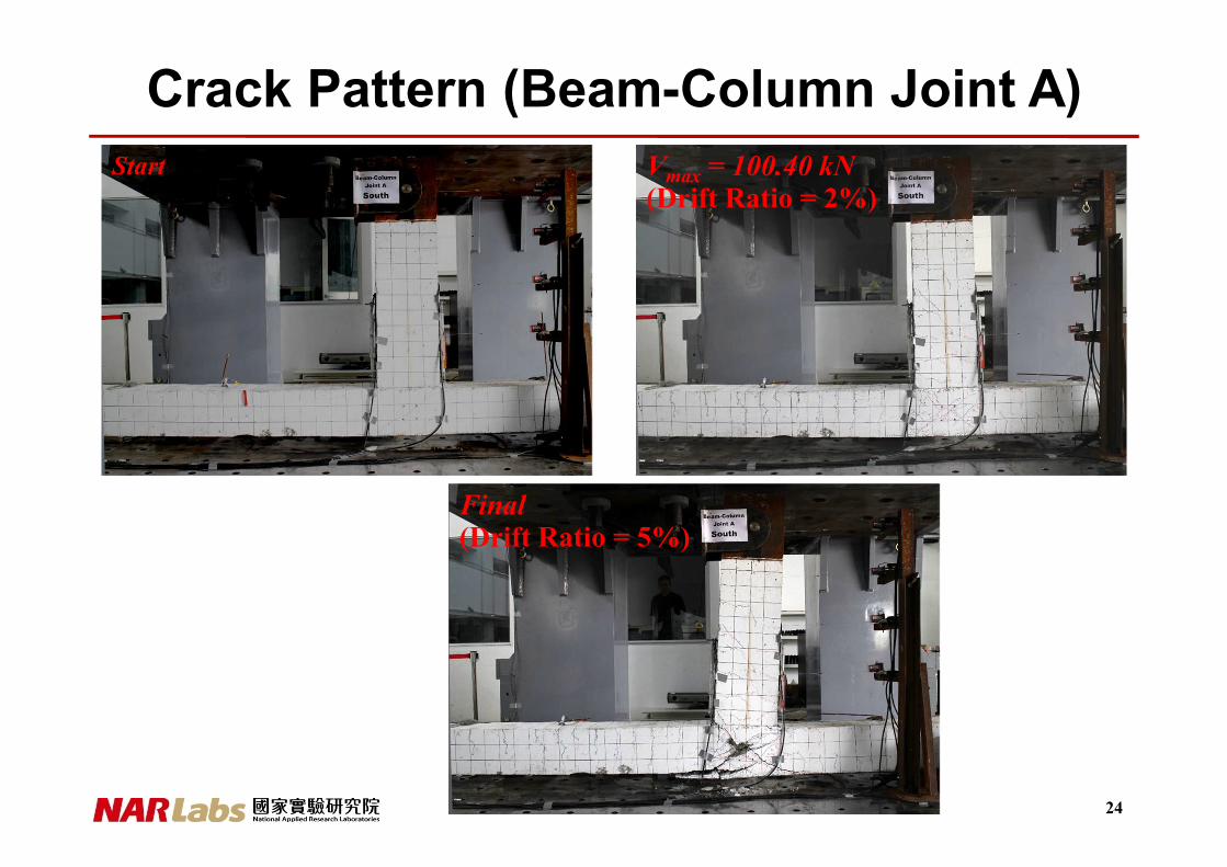
Crack Pattern (Beam-Column Joint A)
24
Start Vmax = 100.40 kN(Drift Ratio = 2%)
Final(Drift Ratio = 5%)

Hysteretic Loop (Beam-Column Joint B)
25
-120 -90 -60 -30 0 30 60 90 120
Displacement (mm)
-200
-100
0
100
200
Late
ralF
orc
e(k
N)
-10 -8 -6 -4 -2 0 2 4 6 8 10
Drift Ratio (%)
Max Load: 157.60 kN @3.0%
Max Load: -157.41 kN @3.0%

Crack Pattern (Beam-Column Joint B)
26
Start Vmax = 157.60 kN(Drift Ratio = 3%)
Final(Drift Ratio = 7%)

Comparison of Hysteretic Loop
• Beam-Column Joint A vs. Beam-Column
Joint B
27
-120 -90 -60 -30 0 30 60 90 120
Displacement (mm)
-200
-100
0
100
200
Late
ralF
orc
e(k
N)
-10 -8 -6 -4 -2 0 2 4 6 8 10
Drift Ratio (%)
Beam-Column Joint A
Beam-Column Joint BMax Load: 100.40 kN @2.0%
Max Load: 157.60 kN @3.0%
Max Load: -100.67 kN @2.0%
Max Load: -157.41 kN @3.0%

Analytical Result• Beam-Column Joint A
• Beam-Column Joint B
28
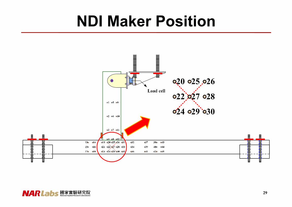
NDI Maker Position
29
20
22
24
25 26
27 28
29 30

Calculation of γavg
30
2avg
d
bhγ
∆ −∆= ×
2
∆−
2
∆−
2
∆
2
∆
is calculated by NDI embedded program
, ,
2
0020
0w
d
hb me mmh mer ≅≅

Comparison of Shear Deformation
• Beam-Column Joint A vs. Beam-Column Joint B
31

Lateral Force vs. Shear Deformation
(Beam-Column Joint A)
32

Lateral Force vs. Shear Deformation
(Beam-Column Joint B)
33

Thanks for your kind attentions