bealeafbi11-250 by order of the commander … · by order of the commander beale air force base ......
TRANSCRIPT

BEALEAFBI11-250 BY ORDER OF THE COMMANDER BEALE AIR FORCE BASE BEALE AIR FORCE BASE INSTRUCTION 11-250 7 JUNE 2005 Flying Operations AIRFIELD OPERATIONS AND BASE FLYING PROCEDURES OPR: 9 OSS/OSA (Capt Monty L. Harshner) Certified by: 9 RW/CC (Col Lawrence L. Wells) Supersedes BEALEAFBI 11-250, 28 April 2004 Pages: 87/Distribution: F COMPLIANCE WITH THIS PUBLICATION IS MANDATORY This instruction implements AFPD 11-2, Aircraft Rules and Procedures, AFI 11-202V3, General Flight Rules, AFI 13-203, Air Traffic Control, AFI 13-204, Functional Management of Airfield Operations, AFI 13-213, Airfield Management, and related supplements. It contains local information and directives pertaining to air operations at Beale Air Force Base (BAFB). This instruction applies to all units associated with, and involved in, flying operations at BAFB. It also applies to all organizations whose personnel operate vehicles on or around the BAFB flight line. Send comments and suggested changes to this instruction on AF Form 847, Recommendation for Change of Publication through channels to 9 OSS/OSA, Beale AFB CA 95903. Send waiver requests pertaining to this instruction to 9 OG/OGV for coordination and consideration. Ensure that all records created as a result of processes prescribed in AFMAN 37-123 (to be replaced by AFMAN 33-363) are maintained in accordance with this manual, and are disposed of in accordance with the Air Force Records Disposition Schedule (RDS) located at https://webrims.amc.af.mil. Contact supporting records managers as required. SUMMARY OF REVISIONS This instruction has been substantially revised and must be completely reviewed.

Chapter 1 INTRODUCTION 1.1. SCOPE. This instruction implements AFPD 11-2. It prescribes procedures and policies concerning operation and control of aircraft on the BAFB flight line and in local airspace, to include air traffic control (ATC) and flight line support functions. 1.2. POLICY. In a single reference this instruction both reiterates higher headquarters guidance and is the source document for numerous organizational instructions. HQ ACC/DORO has reviewed this instruction for compliance with Federal Aviation Administration and Air Force ATC directives. Individual on-base users are responsible for revising their internal guidance in turn. Deviations are authorized when directed by ATC or in emergency situations where adherence would jeopardize safety. 1.3. REGULATION ADMINISTRATION. The 9 RW/CC is responsible for this instruction. The 9 RW/CC may issue waivers or immediate action changes to this regulation when necessary for accomplishment of normal or special mission requirements. All procedural changes affecting ATC must be forwarded to HQ ACC/DORO for review and approval before implementation IAW AFI 13-204. Send suggested changes to 9 OSS/OSA, Beale AFB CA 95903.

Chapter 2 AIRFIELD MANAGEMENT/AIR TRAFFIC CONTROL - GENERAL 2.1. AIRFIELD OPERATING HOURS 2.1.1. Published Hours. Unless modified by Notice To Airmen (NOTAM) or DoD publication, the airfield will open 0700L-2200L, Monday through Thursday and 0700L-1800L on Friday. The airfield is closed on weekends, holidays and down days unless approved otherwise by the 9 OG/CC. 2.1.2. Uncontrolled Field. BAFB does not operate as an uncontrolled airfield. When BAFB Tower is closed, the airfield is closed—takeoff and landing are not authorized except for emergencies. 2.1.3. Reduced Services/Hours. Reduction of flight services and/or airfield hours may become necessary due to periodic manning shortages. Any such reduction will be approved by the 9 OG/CC and will be advertised via NOTAM or flight publication. 2.2. RUNWAYS 2.2.1. Specifications. Runway 15/33 is 12,000 feet long, 300 feet wide; the runway is grooved 75 feet either side of the centerline (center 150 feet grooved). Load-bearing and surface specifications available in the DoD IFR Supplement (see Attachment 1). 2.2.2. Active Runway Selection. The Tower Watch Supervisor will change the active runway in accordance with Federal Aviation Administration (FAA) Order 7110.65, Air Traffic Control, and coordinate the runway change with the Supervisor of Flying (SOF). Runway 15 is the calm wind runway and the primary instrument runway. 2.2.2.1. ATC will notify the SOF, Radar Final Control (RFC), FAA Terminal Radar Approach Control (TRACON), Airfield Management Operations (AM Ops), and Weather when the active runway changes. 2.2.2.2. AM Ops will notify 9 RW/CP, 940 ARW/CP, Transient Alert (TA), Fire Department, and Aero Club of the change. 2.2.3. Runway Operations Suspended. Runway operations will be suspended when an aircraft is disabled on the runway, when an emergency is declared on or near the runway, immediately following an emergency landing, or when any unsafe condition warrants. The Tower Watch Supervisor, SOF and Airfield Management personnel have the authority to suspend runway operations. Notification shall be made to the Tower Watch Supervisor and AM Ops when runway operations are suspended. AM Ops is the only agency authorized to reopen or resume operations to a previously suspended runway. AM Ops will notify the Tower Watch Supervisor when operations may resume.

2.2.4. Runway Closure. The following personnel have the authority to close/open the runway: 9 RW/CC, 9 RW/CV, 9 OG/CC, 9 OG/CD, SOF, Chief of Airfield Management (CAM) or designated representative. Notification shall be made to the Tower Watch Supervisor and AM Ops when the runway is opened or closed. AM Ops is the only agency authorized to reopen or resume operations to a previously closed runway. AM Ops will advise the Tower Watch Supervisor when the runway is open. 2.3. AIRFIELD INSPECTIONS AND CHECKS
2.3.1. Daily Airfield Inspection. The CAM or designated representative will conduct a minimum of one airfield inspection per day. The CAM will ensure personnel authorized to perform airfield inspections are knowledgeable and have an understanding of required distance for obstacles in relation to the runway, taxiways, and parking aprons. 2.3.2. Quarterly Inspections. The airfield manager or designated representative will accompany representatives from Wing Safety, Civil Engineering, and the Foreign Object Damage (FOD) monitor to conduct a quarterly airfield inspection. Members will determine major airfield discrepancies and/or irregularities that require correction and could require runway or taxiway closure. 2.3.3. Daily Opening Check. AM Ops opening airfield checks, at a minimum, must determine the primary takeoff, landing, and taxi surfaces are FOD free; the current bird condition; the runway surface condition. Airfield Management will report the initial Runway Surface Condition (RSC) and changes to ATC. 2.3.4. Runway Surface Condition. AM Ops shall conduct a check anytime it is suspected the RSC has changed. The SOF or the Tower Watch Supervisor may downgrade the runway surface condition from dry to wet. This information will be relayed to the pilot as an advisory only. Example phraseology: “Runway appears wet or SOF advises runway appears wet”.
2.3.5. Additional checks. Will be conducted:
2.3.5.1. When requested by the SOF or ATC. 2.3.5.2. Immediately following any emergency landing, except those involving emergency fuel or physiological conditions, or as directed by the SOF. In the case of an airfield ground emergency, this check shall encompass all of the affected area. (see para 11.5). Note: Unless a runway check has been specifically waived by the SOF, runway operations will be suspended after all In-Flight Emergencies (IFE) until resumed by Airfield Management. 2.3.5.3. For airfield lighting during periods of darkness to ascertain the operability of the airfield lights. 2.3.5.4. For any other situation requiring Airfield Management presence on the airfield, AM Ops will advise ATC when a runway check or inspection is required.

2.3.6. Documentation. Document all airfield inspections using 9 OSS/OSAA Form 1, Airfield (Airdrome) Inspection Checklist. All discrepancies shall be logged on AF Form 3616, Daily Record of Facility Operation and the airfield discrepancy log and tracked until completion. Submit the form to the AM Ops flight data coordinator as soon as possible.
2.4. BIRD WATCH CONDITION 2.4.1. Responsibilities. (See 9 RW OPLAN 91-212, Bird Aircraft Strike Hazard). 2.4.2. Bird Watch Conditions. The 9 OG/CC, SOF and Tower Watch Supervisor have the authority to declare the Bird Watch Condition (BWC), the Tower Watch Supervisor will declare the BWC when the SOF is not on duty.
BWC DEFINITION LOW Normal bird activity; low probability of a strike. MODERATE
Concentrations of birds near the runway or in a location to create a probable hazard to flying; moderate or greater is mandatory if positive dispersal actions are under way; increase vigilance. Update status at least once an hour.
SEVERE
Heavy concentrations of birds on or immediately above the runway or in a location to create an immediate hazard to flying; high potential for a strike; thoroughly evaluate mission need. Update status at least every fifteen minutes.
2.5. NOTICES TO AIRMEN 2.5.1. Responsibilities. BAFB Tower is the primary monitor facility for BAFB NOTAM. AM Ops is the NOTAM issuing facility; forward NOTAM requests to AM Ops. 2.5.2. Navigational Aid Malfunctions. BAFB Tower is also the primary monitor facility for BAFB’s navigational aids (NAVAIDS), using remote status indicator equipment and pilot reports. The Tower Watch Supervisor will coordinate for appropriate NOTAM and/or corrective action on NAVAID malfunctions.
2.5.3. No-NOTAM Preventative Maintenance. BAFB NAVAIDS (see DoD IFR En Route Supplement) may be out of service for no-NOTAM maintenance according to the following schedule:
NAVAID SCHEDULED NO-NOTAM MAINTENANCE Instrument Landing System (ILS)
0600-1000L Tuesday
Tactical Air Navigation (TACAN)
0600-1000L Thursday
Precision Approach Radar (PAR)
0600-0900L Wednesday 1300-1600L Friday

2.6. TERMINAL INSTRUMENT PROCEDURES 2.6.1. Responsibilities. 9 OG/CC is overall responsible for the base Terminal Instrument Procedures (TERPS) program. Requests for instrument procedure development/changes should be directed to 9 OSS/OSA. 2.6.2. Obstacle Penetration. If planned vertical construction or vertically prominent equipment (i.e. cranes, drills, towers) on the airfield has the potential to penetrate a TERPS flight safety zone, Airfield Management will coordinate for a TERPS review of the activity. Any unit that suspects a possible safety zone penetration should include 9 OSS/OSA on their activity coordination package. Off-airfield activity must obtain a TERPS review according to FAA and USAF requirements. 2.6.3. Flight Information Publication (FLIP) Accounts. Requests for changes to FLIP accounts shall be directed to Chief, Airfield Management Operations, the FLIP account manager. 2.6.4. Waivers. Airfield waivers to existing infrastructure, request for new infrastructure or changes to existing waivers must be approved by HQ ACC CE. Airfield construction waivers may be approved at the base level by the 9 RW/CC. All airfield waiver requests must be initiated through 9 CES/CECP (Base Community Planner). All Waiver requests shall be coordinated through Airfield Management before being sent to the 9 RW/CC or HQ ACC. Requests for waivers to any airspace criteria shall be directed to 9 OSS/OSOH. 2.7. AIRFIELD LIGHTING 2.7.1. Systems. Runway 15: High intensity runway lights (HIRL), high intensity approach lights, sequenced flashing lights (SFL) and precision approach path indicator (PAPI) lights. Runway 33: HIRL, SFL, PAPI and high intensity approach lights. 2.7.2. Control. ATC controls the airfield lighting system with the exception of airfield obstruction lights. If BAFB Tower is not available, 9 CES Airfield Lighting will control airfield lighting. In the event 9 CES is unavailable, contact the BAFB Fire Department and they will notify the on-call electrician. 2.7.3. Energy Conservation. In the interest of energy conservation, when there is no traffic forecasted for two or more hours, airfield lighting will be turned off except the rotating beacon and PAPI lights. 2.7.4. Inspections. CE Airfield Lighting will inspect the airfield lighting system daily, Monday through Friday, and report outages to Airfield Management IAW the 9 OSS/OSAA and 9 CES/CEOIE Memorandum of Understanding. 2.8. ATC SERVICES 2.8.1. ATC procedures contained in Chapters 3 through 10.

2.8.2. Class C Service. The FAA provides terminal Instrument Flight Rules (IFR) and Class C radar service to BAFB through Northern California TRACON (NCT). BAFB Tower provides Class C service within a 5 Nautical Mile (NM) radius, surface to 2,100 Mean Sea Level (MSL). BAFB Tower will coordinate with FAA to utilize airspace 2,100 to 2,600 MSL (for definition and dimensions of BAFB’s Class C airspace, see para 4.2). 2.8.3. Radar Final Control (RFC). Normal RFC hours are 0700L-2200L, Monday through Thursday and 0700L-1800L on Friday. The RFC is closed on weekends, holidays, and down days except by NOTAM, approved by the Airfield Operations Flight Commander (AOF/CC) or higher. RFC provides multiple PAR and airport surveillance radar (ASR) approaches. ILS approach monitoring will be provided when requested or as required by FAAO 7110.65 and AFI 13-203. 2.8.4. After Hours. Any unit that requires the airfield to open outside of the published hours must coordinate for 9 OG/CC approval. In lieu of direct coordination, requests may be made through Airfield Operations at DSN 368-3318/3924 or Comm (530) 634-3318/3924. Requests should be received at least 24 hours in advance of a late/early hour’s requirement, or by the preceding Wednesday for weekend operations. 2.8.5. Backup Power. Generators supporting air traffic control and landing systems (ATCALS) equipment have “auto start” capability for uninterrupted ATC service in the case of a commercial power outage. These generators will be run-tested monthly by 9 CE Power Production. 9 CES shall coordinate with ATC prior to testing any of these generators (see ATCALS Equipment Status Operations Letter for more information). 2.9. PAVE PAWS 2.9.1. CAUTION: ALL AIRCRAFT MAINTAIN AT OR ABOVE 2100 MSL WITHIN ½ NM OF PAVE PAWS. In close proximity to the local AN/GSC49 SATCOM terminal (PAVE PAWS) there is the possibility that electronic explosive devices (i.e. ejection seats) may inadvertently fire. 2.9.2. Location. PAVE PAWS is located on the BAB TACAN 072 radial, 4.7 NM (see Attachment 1). 2.10. FLIGHT PLANNING 2.10.1. Filing Requirement. All arrivals and departures must operate on a valid FAA or military flight plan. 2.10.1.1. Domestic flight plans must be received at least 30 minutes prior to departure and contain all information required on a DD Form175, Military Flight Plan. 2.10.1.2. International flight plans must be received at least 2 hours prior to departure and contain all information required on a DD Form 1801, International Flight Plan.

2.10.2. Airborne Filing. IAW AFI 13-213, original flight plans cannot be accepted by BAFB pilot-to-dispatch. Exception: Aircraft Commander on a stop over flight/divert (weather or maintenance) flight plan may re-file or amend the flight plan with AM Ops via any means (radio, telephone, etc.) provided AM Ops personnel verify an original flight plan clearance was filed. AM Ops may verify original flight plan by contacting the original departure location via telephone or flight plan processing computer. 2.10.3. Phone/Fax Filing. In lieu of submitting a hard copy flight plan to AM Ops, on-base units may file by telephone (364-2002) or fax (364-9106) for flights departing BAFB. 2.10.3.1. For faxed flight plans, the signature block must be signed by the pilot- in-command. The original DD Form 175 or DD Form 1801 shall be maintained by the flying unit for one year. 2.10.3.2. After fax transmission the pilot- in-command must call AM Ops to ensure the flight plan was received and can be processed. Requests for an airfield/NAVAID status briefing may be made at this time. To relieve AM Ops workload, aircrews should obtain NOTAMS from the official US NOTAM Office Web Site, www.notams.jcs.mil. 2.10.4. No Flight Plan Arrivals. If ATC cannot locate a flight plan in the ATC system, AM Ops will attempt to verify a valid flight plan by contacting the appropriate Flight Service Station, Command Post, ATC and/or point of departure. If unable to verify the flight plan, a landing clearance will not be issued and the pilot will be advised to contact AM Ops on pilot-to-dispatch frequency to resolve the problem. 2.11. PRIOR PERMISSION REQUIRED
2.11.1. Purpose. To ensure parking space, adequate services, and dissemination of local advisories, prior permission is required (PPR) for all transient aircraft intending to full-stop at BAFB. The PPR system also serves to restrict flight activity during certain exercises and “real world” operations; in this case, the 9 OG/CC will authorize a NOTAM upgrading PPR (for coordination) to Official Business Only (OBO) (for screening). Exceptions: Aircraft with a Distinguished Visitor (DV) Code of six or higher, aircraft emergencies or as an alternate for IFR flights. Aeromedical Evacuation or Special Air Missions are exempt from PPR/OBO restrictions, but are required to obtain a PPR number for tracking/notification. 2.11.2. Obtaining a PPR Number. Transient pilots should contact BAFB AM Ops at DSN 368-2002 or commercial (530) 634-2002. 2.11.3. ATC Verification. ATC will verify PPR status for all arrivals not appearing on the 9 RW or 940 ARW flight schedule. If it is determined that AM Ops has not issued a PPR number to that flight, full stop landing clearance is at the discretion of the Tower Watch Supervisor (depending on traffic). Services and parking may not be available for no-PPR arrivals. 2.11.4. Practice Approaches. No PPR is required (civilian approaches see para 2.12.1.; transient military see para 4.6.).
2.12. CIVIL AIRCRAFT 2.12.1. Practice Approaches. Civilian practice approaches, to include use of the ILS, on a non-interference basis are encouraged at BAFB. Practice approaches during wing flying hours may be disapproved by the Tower Watch Supervisor or the SOF if the practice will impair, delay or compromise the mission of any military aircraft. 2.12.1.1. All civil aircraft practice approaches will terminate in low approach unless approved IAW para 2.12.2. 2.12.1.2. Minimum altitude flown must be at or above the missed approach altitude.
2.12.2. Landing Requirements. Except for emergencies, no civil aircraft may touch down unless the pilot in command has accomplished the requirements of AFI 10-1001, Civil Aircraft Landing Permits. Note: BAFB Aero Club aircraft are exempt from these requirements.
2.12.2.1. The 9 RW/CC or designated representatives may approve or disapprove civil aircraft landing applications (DD Forms 2400, Civil Aircraft Certificate of Insurance; 2401, Civil Aircraft Landing Permit; and 2402, Civil Aircraft Hold Harmless Agreement). 2.12.2.2. Contact BAFB AM Ops (9 OSS/OSAA) or the AOF/CC (9 OSS/OSA) for assistance. 2.12.2.3. Unauthorized landings will be categorized emergency, inadvertent, or intentional, and will be handled in accordance with AFI 10-1001, Chapter 10. Handling may include armed Security Forces response, landing fees, punitive fees, aircraft detention, and supply and service charges. 2.12.3. Civil Air Patrol (CAP). CAP missions (indicated by the use of a designated CAP callsign) are considered military flights and are exempt from the requirements of this section. CAP flights shall comply with the BAFB Aero Club procedures in para 9.3. through para 9.6.
2.13. MISCELLANEOUS INFORMATION 2.13.1. Wear of Hats. (See AFI 36-2903 BAFB Sup 1 for no hat areas). 2.13.2. Taking Photographs. Contact 9 RW/PA regarding photographs of BAFB. AM Ops may take pictures without prior permission, when official business dictates. 2.13.3. Flight Line Smoking Policy. IAW AFOSHSTD91-100 smoking is prohibited in the flight line area except where designated by the installation fire chief in coordination with the functional manager and (or) supervisor.

Chapter 3 AIRCRAFT GROUND OPERATIONS 3.1. CONTROLLED MOVEMENT AREAS 3.1.1. Procedure. ATC will exercise positive control of all aircraft and vehicle traffic in their respective movement areas. Except for runway operations on Local Control (“Beale Tower”) frequency, all traffic shall contact Ground Control (“Beale Ground”) prior to entering their applicable movement area, and shall maintain two-way radio contact while inside the area (exception for U-2 Mobiles, see para 5.2.2.4.). Aircraft shall state their location on the airfield when requesting taxi. 3.1.2. Aircraft Controlled Movement Area. Defined as all paved areas designated for aircraft movement (see Attachment 2), except the following areas:
3.1.2.1. Taxiway M. 3.1.2.2. Dock 7 area (T-38 dock). 3.1.2.3. Docks 1-6 area (parking apron east of Arnold Ave.). 3.1.2.4. Taxiway A north of the fence line.
3.1.3. Vehicle Controlled Movement Area. Includes the runway and overruns and all paved and grassy areas from 100 feet west of the runway and overrun to the eastern edge (flight line side) of taxiway Foxtrot (see para 13.7.1.). 3.1.3.1. Vehicle operations outside this area are the responsibility of the operator. Vehicles shall give way to aircraft at all times. 3.1.3.2. Aircraft towing shall comply with vehicle movement area procedures and approval procedures in para 3.4.2. 3.1.3.3. Operators not equipped for or proficient in radio communications may be escorted (see Chapters 12 and 13 for flight line driver qualifications and traffic procedures). 3.1.4. Hours. Controlled Movement Area requirements apply whenever the airfield is open (whenever BAFB Tower is open, as published or by NOTAM) and during closed hours according to para 13.7.1.2. 3.1.5. Exemption. Fire Department/Crash/Rescue/Dragon Video vehicles responding to a flight line emergency do not require ATC permission to enter the Vehicle Controlled Movement Area. ATC will be aware of the response in progress. However, emergency response crews should establish radio contact with ATC as soon as practical. IMPORTANT: ATC permission is ALWAYS required to proceed onto the runway.

3.2. HOLD LINES 3.2.1. Instrument Hold Lines. Two solid yellow instrument hold lines traverse taxiways B and E, accompanied by the painted letters ILS Holdline (see Attachment 1). The markings consist of two yellow solid parallel lines spaced two feet apart and connected by pairs of yellow solid vertical lines spaced 10 feet apart. A sign with the inscription “INST” in white on a red background is installed next to these hold-position markings. The designation for the instrument holding position, INST, is painted on the runway side of the line and is readable as you face the runway (IMPORTANT: flight line drivers see para 13.7.). 3.2.1.1. Aircraft and vehicles may proceed past the instrument hold line and up to the runway hold line unless ceiling is less than 800’ Above Ground Level (AGL) or visibility is less than 2 Statute Miles (SM) or ATC specifically instructs to hold at the instrument hold line. Anytime the rotating beacon is on vehicles shall not proceed past the instrument hold line without ATC approval. 3.2.1.2. To eliminate potential PAR signal interference, ATC will ensure C-130 and larger aircraft on taxiway C (runway 15 active) or taxiway D (runway 33 active) taxi all the way to the runway hold line for departure, or all the way to taxiway F after exiting the runway. 3.2.2. Runway Hold Lines. Runway hold lines protect the active runway from vehicle or aircraft activity that would endanger flying operations. With the exception of active U-2 mobile operations, explicit ATC permission is always required to cross a runway hold line in the direction of the runway. 3.3. SPECIAL TAXI CONSIDERATIONS 3.3.1. Anti-Hijacking. All aircraft shall obtain taxi clearance prior to moving out of parking. If ATC observes an aircraft move out of parking without contact or coordination, Hijack Prevention procedures will be initiated according to the base OPLAN. Aero Club aircraft remaining in the designated Aero Club parking area are exempt from this requirement. 3.3.2. T-38 Parking. Locally-based T-38 aircraft may taxi into and out of their parking spots on established taxi lines without the use of wing tip marshallers if the obstructions present are either permanent objects, fire bottles, ground equipment in designated areas and behind marked lines on the pavement, or other T-38s in designated parking spots. 3.3.3. Airfield Blind Spots. While all aircraft ground movement is radio controlled by ATC (see para 3.1.), certain areas are not visible from the BAFB Tower (see Attachment 1). ATC separation in these areas is not visual; taxi with caution. 3.3.4. Restricted Areas. A portion of Taxilane G is within a restricted area on the transient parking ramp. Pilots must receive Ground Control approval to enter this or any other restricted area. Ground Control shall coordinate with Security Forces Law Enforcement (LE) Desk prior to directing aircraft or vehicle traffic through a restricted area (see para 12.9.).

3.3.5. Ground Delays. To plan the flow of air traffic, and to expedite ATC “release” coordination, departures should be ready for takeoff upon reaching the runway hold line. Pilots shall advise Ground Control as early as possible if they cannot accept an immediate IFR departure. 3.3.6. Taxiway Edge Lighting Outages. Aircraft movement is restricted to daytime Visual Flight Rules (VFR) operations when the taxiway edge lights are out of service or otherwise unavailable.
3.4. AIRCRAFT TOWS 3.4.1. Coordination. Maintenance Operations Center (MOC) will coordinate all aircraft tows with ATC and Security Forces. 3.4.2. Flight Line Procedures. Prior to entering the vehicle Controlled Movement Area (see para 3.1.3.) tow crews shall obtain Ground Control approval using aircraft radios or the Ramp Net, and shall monitor that frequency until exiting the movement area. For security purposes, while aircraft tows that remain within the confines of aircraft parking ramps do not require Ground Control approval, tow crews shall notify Ground that the tow is commencing and when the tow is complete. 3.5. ENGINE RUNS 3.5.1. Coordination. MOC will coordinate all aircraft engine runs with the ATC and Security Forces. 3.5.2. Flight Line Procedures. Maintenance personnel shall obtain engine run clearance from Ground Control and inform Ground of engine run termination. 3.5.3. Jet Blast. For engine runs and taxi power, aircraft commanders are responsible for ensuring the required distance fore and aft of jet engines is clear according to aircraft specifications. 3.6. NAVAID CHECKPOINTS 3.6.1. Location. TACAN check points are located at either end of the runway (taxiways B and E), depicted by a 10-foot painted circle. Additionally, two Inertial Navigation System (INS) checkpoints are located on the transient parking ramp at DV Spots 1 and 2 (see Attachment 1). 3.6.2. Checkpoint Information. On taxiways B and E, checkpoint information is displayed on lighted signs adjacent to the ground markings. BAFB’s NAVAID checkpoint information is as follows.

LOCATION RADIAL and DME or LAT/LONG
Taxiway B TACAN CH 23 343/1.2 VOR (MYV) 110.8 047° ELEV 113 ft
Taxiway E TACAN CH 23 128/1.1 VOR (MYV) 110.8 061° ELEV 105 ft
DV Spot 1 (most easterly spot) 39° 08.7’N 121° 25.8'W, Magnetic Variation: E16° 5.0', ELEV: 117 ft
DV Spot 2 (most westerly spot) 39° 08.7'N 121° 25.8'W, Magnetic Variation: E16° 5.0', ELEV: 115 ft
3.7. FIRE SUPPRESSION 3.7.1. Responsibilities. Prior to wing flying, the Fire Department will ensure one major crash vehicle is capable of reaching the end of the either runway overrun within 3 minutes. The Fire Department shall notify 9 OG/CC, the SOF and AM Ops whenever firefighting capability cannot fully support flight operations. In this case, Airfield Management will either close the runway or restrict operations to base-assigned aircraft only, depending on the 9 OG/CC or SOF determination. AM Ops will also send a NOTAM establishing an airfield restriction (i.e. official business only) as directed by the 9 OG/CC. 3.7.2. Flight Line Fire Extinguishers. 9 CES/CEF is the “owner” responsible for the care and maintenance of flight line fire extinguishers. 3.7.2.1. Fire extinguishers shall be placed in storage except when positioned fo r specific airfield activity. Extinguishers will be stored at a “ready line” (“dead line”): CO2 extinguishers between shelters M and N, Halon extinguishers behind parking spot 4. 3.7.2.2. Users of the flight line fire extinguishers (U-2 Maintenance, T-38 Maintenance, and TA) shall transport fire extinguishers as needed between storage and their required flight line positions, and will assist 9 CES/CEF in monitoring the safe working condition of all extinguishers. 3.7.3. Improperly Placed Fire Extinguishers. MOC is the point of contact for relocating improperly placed fire extinguishers on the airfield. Generally, AM Ops will advise MOC and MOC will contact the appropriate user to correct the problem. 3.8. TRANSIENT PARKING 3.8.1. Transient Alert. TA provides flight line marshalling services to transient aircraft from 0700-1600 Mon-Fri. 3.8.2. No Transient Alert. Outside of TA service hours, AM Ops will notify the MOC for parking assistance, in which case the following rules apply: 3.8.2.1. All transient aircraft will be parked in the DV parking spots, if available.
3.8.2.2. If the DV spots are full and the aircraft can deplane qualified crew for marshalling, the aircraft may park on spot 1 or spot 17. If crew marshalling is not an option, the aircraft shall park on the centerline of Taxilane G.
3.8.2.3. Transient helicopters shall park on spots A and B (in front of the SR-71 static display). 3.9. HI-LINE DOCK OPERATIONS 3.9.1. Purpose. 9 LRS utilizes the Hi-Line Docks (located north of hangar 126) for cargo pallet-building.
3.9.2. Coordination. Transportation shall coordinate with Airfield Management prior to Hi-Line Dock operations. Airfield Management will only approve activities within the designated area (see Attachment 17), to remain at least 200 feet from taxiway H.

Chapter 4
LOCAL FLYING PROCEDURES Note: This chapter contains general flying procedures and information. Specific U-2, T-38, RQ-4, 940 ARW KC-135 and Aero Club procedures are detailed in Chapters 5 through 9, respectively. 4.1. FLYING AREAS 4.1.1. Local Flying Area. The BAFB local flying area is defined by connecting the following points:
LAT/LONG GEOGRAPHIC LOCATION
43° 35'N 119° 02'W Burns, OR 39° 00'N 120° 00'W Lake Tahoe, CA 37° 57'N 121° 15'W Stockton, CA 38° 58'N 123° 44'W Point Arena, CA 43° 42'N 124° 13'W Reedsport, OR 43° 35'N 119° 02'W Burns, OR
4.1.2. Instrument Training Area. The BAFB instrument training area is defined by connecting the following points:
LAT/LONG GEOGRAPHIC LOCATION 40° 13'N 120° 12'W Amedee, CA 39° 35'N 120° 28'W 39° 28'N 121° 00'W 39° 00'N 121° 45'W 39° 09'N 122° 44'W 39° 25'N 121° 28'W 40° 48'N 121° 28'W 40° 49'N 120° 19'W 40° 13'N 120° 12'W Amedee, CA
4.2. CLASS C AIRSPACE 4.2.1. Boundaries. BAFB Class C airspace is defined as follows; radials and distances are from the center of the runway (see Attachment 13):
RADIUS SECTOR ALTITUDE 5 NM All sectors SFC up to and including 4,100 MSL 10 NM R-127 clockwise to R-007 1,600 MSL up to and including 4,100 MSL 10 NM R-007 clockwise to R-127 2,600 MSL up to and including 4,100 MSL

4.2.2. Class C Service. Class C radar service (see FAA Aeronautical Information Manual(AIM) or FAAO 7110.65) is provided by Northern California TRACON (NCT) and BAFB Tower. NCT and BAFB Tower will coordinate sequencing and separation between IFR and VFR aircraft. Coordination procedures are contained in an ATC letter of agreement. 4.3. SUPERVISOR OF FLYING 4.3.1. Role. The SOF is the direct representative of the 9 OG/CC and is the focal point for command and control of flight operations. The SOF is a group-level position and is the 9 OG/CC’s representative over-seeing flight operations. Decision authority is delegated to this position to accomplish the mission. 4.3.2. Responsibilities. Procedures are contained in AFI 11-418, Operations Supervision and AFI 11-418, BAFB Supplement 1, 9 RW Operations Supervision. Note: IAW AFI 13-203 non-ATC agencies must coordinate with ATC prior to transmitting on ATC frequencies and may not issue ATC instructions. If necessary, ATC may interrupt transmissions to issue ATC instructions. 4.4. FREQUENCIES 4.4.1. Locally Assigned Frequencies. (See DoD FLIP IFR – Supplement for further information).
FREQUENCY USE 276.15, 119.4. Local Control 287.0 U-2 Local Control Discrete 228.4, 121.6 Ground Control 385.6 Emergency Discrete 269.6, 282.35, 124.55 Single Frequency Approach
4.4.2. Automatic Terminal Information Service (ATIS). ATIS is available on 273.5 MHz. The ATIS shall be operated IAW DoD FLIP IFR – Supplement. ATIS broadcasts shall be made upon facility opening and shall continue until the facility closes.
4.5. LOCAL AIRCRAFT PRIORITIES 4.5.1. Local Priorities. Local priorities do not take precedence over the basic air traffic control priorities in FAAO 7110.65 (i.e. Emergency/Distress, Lifeguard, Med Evac, etc.). Note: Priorities 4 through 7 may be adjusted at the discretion of the SOF.
1. National Airborne Operations Center (NAOC) Alert 2. “Real world” Emergency War Order (EWO) 3. Operational missions/Controlled Departure Times (see para 4.5.2) 4. U-2 High flight departures/recoveries 5. U-2 Interview Sorties (AF 1/2/3) and Basic Qualification Sorties (BQ 1/2)

6. IFR Arrivals 7. IFR Departures
4.5.2. Controlled Departure Times. Controlled departure times are used to ensure departure from 5 minutes prior to 10 minutes after the filed departure time. Controlled departure times must be filed with AM Ops. Pilots are encouraged to also inform Ground Control of their controlled departure time when requesting clearance. 4.5.3. Traffic Abatement. Due to the nature of U-2 operations, T-38 and KC-135 tower/radar pattern training should be de-conflicted by scheduling to avoid known times of multiple U-2 pattern activity. 4.6. TRANSIENT MILITARY PRACTICE APPROACHES 4.6.1. Approval. Practice approaches on a non-interference basis are encouraged at BAFB. The SOF will approve transient military approaches if the practice will no t impair, delay or compromise the mission of 9 RW or 940 ARW aircraft. 4.6.2. Coordination. To avoid being turned away, transient pilots expecting practice approaches are encouraged to check BAFB’s daily flying schedule during their flight planning. This may be done by contacting AM Ops at (530) 634-2002 (DSN 368-2002) or Command Post at (530) 634-5700 (DSN 368-5700). 4.6.3. Non-Military Practice Approaches. (See para 2.12.1.). 4.7. VFR TRAFFIC PATTERNS Note: Use extreme caution mountainous terrain north, northeast, and northwest of the airfield. 4.7.1. Traffic Pattern Delays. To allow air traffic planning and to preempt erroneous ATC “release” coordination, pilots should advise Ground Control as early as possible if they intend to delay in the VFR/IFR traffic pattern prior to departing on their delivered clearance (ground delays see para 3.3.5.). 4.7.2. Closing the VFR Pattern. VFR minima for USAF aircraft is 1500’ ceiling and 3 miles visibility. The Tower Watch Supervisor or SOF may close the VFR traffic pattern whenever weather conditions prevent visual separation of aircraft. Minimum ceiling requirements for the VFR patterns are as follows:
VFR PATTERN ALTITUDE REPORTED CEILING T-38 Overhead (2100’ MSL) 2500’ T-38 Overhead (1600’ MSL) 2000’ U-2 Rectangular (1100’ MSL) 1500’ U-2 Overhead (1600’ MSL) 2000’ U-2 Low Closed (1100’ MSL) 1500’

4.7.3. Rectangular Pattern (Attachment 3). Pattern altitude 1,100 MSL. East pattern standard; west pattern authorized when approved or directed by ATC. 4.7.4. T-38/Fighter Overhead Pattern (Attachment 4). Pattern altitude 2,100 MSL. West pattern standard; east overhead pattern authorized when approved or directed by ATC. 1,600 MSL pattern available upon request and ATC approval when no U-2 aircraft operating in the pattern. 4.7.5. U-2/T-38/KC-135 Low Closed Traffic (Attachment 5). U-2 pattern altitude 540 MSL to 1,100 MSL; T-38/KC-135 pattern altitude 680 to 2,100 MSL. West pattern only. 4.7.6. U-2/KC-135 Overhead Pattern (Attachme nt 6). Pattern altitude 1,600 MSL. East pattern standard; west pattern authorized when approved or directed by ATC. 4.7.7. U-2 Closed Traffic (Attachment 7). Pattern altitude is 1,100 MSL. East pattern standard; west pattern authorized when approved or directed by ATC. Present position closed is expected when ATC issues/approves closed traffic. Aircraft must be at least 400’ AGL before commencing the turn out. 4.7.8. Aero Club/Helicopter Pattern (Attachment 8). Pattern altitude 1100 MSL. West rectangular pattern; east pattern authorized when approved or directed by ATC. 4.7.9. T-38/Fighter Closed Traffic (Attachment 9). Pattern altitude 2,100 MSL (1,600 MSL available reference traffic and ATC approval). West pattern standard; east pattern authorized when approved or directed by ATC. If ATC approves a T-38/fighter aircraft for closed traffic, the pilot may not turn crosswind or closed prior to departure end of runway unless specifically directed or approved by ATC. 4.7.10. U-2 Simulated Flameout (SFO) Pattern (Attachments 10 and 11). High Key altitude 1,100 to 2,100 MSL; Low Key altitude 600 to 1,100 MSL. East pattern standard; west pattern are authorized when approved or directed by ATC (see Chapter 5). 4.8. NOISE ABATEMENT 4.8.1. Restrictions. Aircraft should avoid flying over the main base area, hospital or base housing area. 4.8.2. Noise Complaints. Refer noise complaints to Public Affairs (9 RW/PA). 4.9. GO-AROUND/SFO AND OVERHEAD PROTECTION 4.9.1. Restrictions. To ensure appropriate separation between departures, low approach/touch-and-go transitions, go-arounds, and aircraft in the SFO/overhead pattern, the following restrictions apply to all aircraft unless deleted or amended by ATC (see the Letter of Agreement between Northern California TRACON and BAFB Tower).

4.9.2. VFR Pattern Protection. When the VFR pattern is in effect, all departing aircraft, except U-2s releasing pogos, shall maintain at or below 1,000 MSL until departure end of the runway, then climb out according to ATC clearance. When other pattern traffic is lower than 1,500 MSL, ATC will amend the 1,000-foot restriction by issuing detailed climbout instructions. 4.9.3. Offset Initial. To ensure 500 feet of lateral separation between U-2s releasing pogos and aircraft in overhead/SFO pattern, ATC shall direct aircraft in the overhead/SFO pattern to offset 500 feet left/right of the runway. The aircraft will break in the same direction as the offset, so as not to overfly the runway. ATC Phraseology: “OFFSET INITIAL TO THE LEFT/RIGHT, U-2 ON THE RUNWAY FOR DEPARTURE.” Pilots will read back the offset instruction and add “OFFSET LEFT (RIGHT)” to the Initial/High Key position report. Then offset, no less than 500 feet, as required to keep the departing aircraft in sight. 4.9.4. Standard Go-Around. If ATC directs or the pilot initiates a go-around, the pilot shall fly runway heading, maintain at or below 1,000 MSL until crossing the departure end of the runway, then climb out as instructed by approach control (or maintain VFR to stay with Tower). When pattern traffic below 1,500 MSL is a factor, ATC will issue detailed go-around instructions in lieu of the standard 1,000-foot restriction. 4.9.5. Offset Go-Around. If ATC directs “GO-AROUND LEFT/RIGHT SIDE,” the pilot shall execute standard go-around (see para 4.9.4) with a ground track offset 500 feet left/right of the runway. Pilots are responsible for determining the 500-foot distance. Standard go-around climb restriction applies. 4.9.6. Local Climb Out. Defined as: Maintain 1000’ until departure end, fly runway heading, climb and maintain 3000. When desiring to depart into the radar pattern local pilots may be instructed to “EXECUTE LOCAL CLIMBOUT”. 4.10. HELICOPTER OPERATIONS 4.10.1. Arrival. If possible, helicopters should enter BAFB Class C airspace for a west downwind at or below 600 MSL. Helicopters shall not overfly other taxiing aircraft, flight line buildings, or parking ramps. 4.10.2. Helipads. The primary helicopter landing areas are the intersection of taxiways F and D and the intersection of taxiways F and C; however, helicopter landing is authorized to all taxiways except taxiway A (see Attachment 1). 4.10.3. Taxiing. Helicopters not capable of ground taxi will hover taxi along established (paved) taxi routes. Use caution to prevent rotor blast damage to equipment/personnel. 4.11. UNUSUAL MANEUVERS 4.11.1. Approval. Maneuvers that are not essential to mission accomplishment or safety of flight require approval from the Supervisor of Flying. ATC will disapprove pilot requests to

conduct any maneuver which could jeopardize flight safety or which presents a hazard to other aircraft, personnel, or ground facilities. 4.11.2. Federal Aviation Regulation Deviations . Maneuvers requiring a waiver to Federal Aviation Regulations (FAR) must be submitted to AM Ops at least 30 days in advance to provide adequate coordination time. These waivers require 9 OG/CC approval prior to forwarding to the FAA. 4.12. INTERSECTION DEPARTURES 4.12.1. Authorized Intersections. Intersection departures are permitted from any taxiway by pilot request. BAFB operations that routinely use intersection departures will automatically be taxied to the appropriate intersection, which the pilot may refuse if the full length is desired. 4.12.2. Distance Remaining. For non-local aircraft, ATC will issue the distance remaining from the departure intersection to the end of the runway. These distances are shown in Attachment 1. 4.12.3. Nighttime Departures. Between sunset and sunrise, or when the intersection is not visible from BAFB Tower, ATC will not allow an aircraft to taxi into position and hold at the intersection. 4.13. OPPOSITE DIRECTION ARRIVALS/DEPARTURES 4.13.1. Approval. Pilots may request opposite direction arrival/departure at any time in the pattern or on the ground. ATC may disapprove or delay requests based on existing traffic or if there is insufficient lead time to coordinate with Northern California TRACON (if entering/leaving the Class C surface area). 4.13.2. ATC Cutoffs. An opposite direction departure must be on a course at least 45-degrees from runway heading before a normal direction arrival reaches a point 10 miles on final. An opposite direction arrival must cross the landing threshold before a normal direction arrival reaches a point 10 miles on final. 4.14. ADF APPROACH 4.14.1. Restrictions. BAFB's Practice ADF approach (to AM 1410 located across from the Fairgrounds) is Visual Meteorological Conditions (VMC) ONLY, minimum 5 SM visibility, and for 9 RW USE ONLY (see Attachment 16). Do not confuse this with the ILS RWY 14 (ADF procedure turn to Marysville/Yuba County). 4.14.2. Simulated Flameout. U-2s terminating the approach in an SFO (see para 5.3) shall, on initial contact with ATC state the intended high key altitude and state also if runway crossing is required. Do not cross the runway centerline below 2,600 MSL without ATC permission. 4.15. CALL SIGNS

4.15.1. The following call signs are used to differentiate types of U-2 operations:
CALL SIGN OPERATION Pinon 10-19 Airshows/flybys Pinon 20-29 Functional Check Flight (FCF) and
Operational Test & Evaluation (OT&E) Pinon 50-59 Continuation training (low) Pinon 60-69 Student training (low Pinon 70-79 Student training (high) Pinon 90-99 Continuation training (high)
4.15.2. The following are locally designated call signs reserved for the individual indicated and may be used for either U-2 or T-38 flights:
CALL SIGN INDIVIDUAL 01 9 RW/CC 02 9 RW/CV 03 9 OG/CC 04 9 OG/CD 05 9 OSS/CC 06 1 RS/CC 07 99 RS/CC
4.16. REDUCED SAME RUNWAY SEPARATION 4.16.1. Restrictions. Reduced Same Runway Separation (RSRS) may NOT be applied if any of the following conditions exists:
4.16.1.1. A non-base-assigned or Aero Club aircraft is involved.
4.16.1.2. Any situation involving an emergency aircraft. 4.16.1.3. An aircraft involved is cleared for the option. 4.16.1.4. If weather conditions preclude BAFB Tower from visibly determining applicable separation. 4.16.1.5. RCR less than 12. 4.16.1.6. T-38 low approach behind a T-38 touch-and-go. 4.16.1.7. T-38 no-flap full stop landing behind T-38 full stop landing. Note: Pilots will add “no-flap” to their final pattern request anytime a no-flap full stop landing is planned.
4.16.2. Separation. Use the following guidance to apply RSRS:

4.16.2.1. 3,000 feet (6,000 feet at night or when runway is wet):
4.16.2.1.1. T-38 full stop behind a T-38 full stop/touch-and-go/low approach. 4.16.2.1.2. T-38 touch-and-go behind a T-38 touch-and-go/low approach. 4.16.2.1.3. T-38 low approach behind a T-38 low approach.
4.16.2.2. 6,000 feet:
4.16.2.2.1. T-38 low approach behind a T-38 full stop. 4.16.2.2.2. U-2 full stop behind a T-38 full stop/touch and go/low approach. 4.16.2.2.3. T-38 formation flight in front or behind another T-38 (Reduced separation is measured between the trailing aircraft in the lead flight and the lead aircraft in the trailing flight). 4.16.2.2.4. T-38 touch-and-go behind a T-38 full stop (daytime, VFR, dry runway only).
4.16.2.3. 8,000 feet: A U-2 full stop behind a T-38 formation full stop.
4.17. VFR REPORTING POINTS (See Attachment 23).

Chapter 5 U-2 OPERATIONS 5.1. U-2 DEPARTURE PROCEDURES 5.1.1. Intersection Departure. U-2s may depart runway 15 from taxiway C and runway 33 from taxiway D. 5.1.2. High Flight Release. Due to additional coordination between BAFB Tower, NCT and Oakland Center, U-2 high flights may experience some delay depending on traffic and ATC workload.
5.1.3. Tactical Departure. Defined as a spiraling east turn, unrestricted climb to 11,000’ MSL, remaining within 5 NM of BAB TACAN then direct to PYNUN (SAC R345/90). Tactical departures will not be filed in conjunction with a Departure Procedure. Tactical departures will be accomplished in VMC only. Note: A spiraling climb to the west is unavailable due to radar coverage limitations. 5.1.3.1. ATC will approve a climbing turn east of the runway based existing traffic. Pilots will not begin turn until 400’ AGL and will not exceed 30 degrees of bank. 5.1.3.2. If initial climb to 11,000’ MSL is unavailable, ATC will relay an amended climb altitude (determined by approach control). If unable to accept this altitude, the pilot should state intentions to depart non-tactical or delay until the unrestricted climb is available.
5.1.3.3. Pilots shall write “Request Tactical Departure” in the remark section of the flight plan and should repeat the request to Beale Ground when calling for clearance (Example: “Beale Ground, PINON 01, request IFR clearance to (destination), Tactical Departure”). ATC will clearly state Tactical Departure when relaying IFR clearance to the pilot along with any modifications/restrictions prior to giving takeoff clearance.
5.1.3.4. Upon reaching tactical climb altitude, pilot shall proceed direct to PYNUN and thereafter according to their IFR clearance. 5.2. U-2 SUPPORT VEHICLE (MOBILE) OPERATIONS
5.2.1. Responsibility. The U-2 Mobile officer is responsible for all vehicle operations on the runway during launch, transition, and recovery operations. This includes accompanying maintenance “Pogo” crews as necessary (see para 13.7.3.5.).
5.2.2. Communications. U-2 aircraft and Mobiles normally operate on BAFB Tower frequency 287.0 (or Norcal Approach frequency during PAR/ASR approaches). Mobiles shall not perform ATC functions or transmit ATC instructions or clearances, and will limit use of ATC frequencies to those transmissions necessary for safe U-2 operation.

5.2.2.1. If Ultra High Frequency (UHF) equipped, Pogo crews shall monitor 287.0 to maintain situational awareness and to communicate with BAFB Tower if absolutely necessary to ensure safety. 5.2.2.2. Prior to operating on the runway, the U-2 Mobile officer shall perform a radio check with ATC.
5.2.2.3. After exiting the runway, the Mobile officer will ensure all accompanying vehicles and equipment are clear of the runway before reporting off.
5.2.2.4. Mobiles may change from ATC frequency in the interest of flight following or safety, as long as contact is maintained with the SOF. 5.2.3. Departures. Mobiles and Pogo trucks are automatically cleared onto the runway when their assigned aircraft is cleared onto the runway. 5.2.4. Arrivals. Mobiles are automatically cleared onto the runway when their aircraft crosses landing threshold. 5.2.4.1. Pogo vehicles may enter the runway with ATC permission and in trail of a U-2 full-stop landing.
5.2.4.2. Mobile officers may relay runway clearance to Pogo crews upon receiving permission from ATC.
5.2.4.3. The Pogo crew will normally enter the runway from the taxiway nearest to where the aircraft stopped. Mobile shall coordinate and receive ATC approval for Pogo to enter for operations that deviate from this paragraph. 5.2.5. Staging Areas and Run-In. When runway 15 is active, Mobiles may use either taxiway A or taxiway B for staging and run-ins to the runway. Use caution for Aero Club aircraft taxiing on taxiway A. When runway 33 is active, Mobiles shall use taxiway E for staging and run- ins to the runway. 5.2.6. Support Priorities. In the event of a simultaneous recovery and departure, the Pogo crew will give priority to the departure unless the recovery is blocking the runway, or unless another priority is directed by the SOF. 5.3. U-2 SIMULATED FLAMEOUT PROCEDURES 5.3.1. General. Simulated Flameout (SFO) pattern training is critical to the pilots of the 9 RW. An SFO pattern begins at high key and ends 10 feet above the runway normally followed by a landing or low approach. The pattern must be flown from start to finish to achieve the desired training objective. After leaving high key, ATC will only issue pattern adjustments or discontinue the approach if required for flight safety. 5.3.2. Restrictions. The SFO pattern (see para 4.7.10) is closed if any of the following conditions exist:

5.3.2.1. Between sunset and sunrise. 5.3.2.2. Below VFR weather conditions. 5.3.2.3. Ceiling less than 500 feet above high key altitude. 5.3.2.4. Less than 3 SM flight or ground visibility. 5.3.2.5. ATC workload of 8 or more aircraft. 5.3.2.6. Directed by SOF. 5.3.3. SFO Procedures. The pilot shall obtain ATC approval for an SFO. The request should include the desired high key altitude. High key altitude is 1,100 to 2,100 MSL.
5.3.3.1. Phraseology: “(Call Sign), REQUEST (High Key Altitude) HIGH KEY.”
5.3.3.2. In order to minimize potential traffic pattern conflicts, ATC shall not approve 2,100 MSL high key when T-38 aircraft are in the 2100’ MSL VFR overhead/closed/low closed pattern. Exception: T-38 aircraft proceeding to a 5 mile straight- in are not considered in the 2100’ MSL VFR overhead/closed/low closed pattern. 5.3.3.3. The pilot will report high key, normally over the first two thirds of the runway. An abnormal or extended high key (beyond first two thirds of the runway) requires prior coordination with ATC. 5.3.3.4. Turns out of high key will be to the east unless a west SFO pattern is approved or directed by ATC. Exception: A high key, normally 1,100 MSL, abeam taxiway “D” (RWY 15) or abeam taxiway “C” (RWY 33) shall turn out to the west. Remain within 3 NM of the runway throughout the turn. Pilots will specifically request high key “ABEAM C/D.” 5.3.3.5. Low key altitude is normally 600 to 1,100 MSL near the approach end of the runway. Low key for SFOs abeam taxiway “D” or taxiway “C” will normally be between taxiway “D” and taxiway “C.”
5.3.4. Simulated Glide to High Key. Since an engine can flame out at any time, it is crucial for pilots to practice SFO patterns from various altitudes and geographical positions.
5.3.4.1. Pilots may practice SFO patterns from a requested altitude and geographical position with ATC approval. Example: “(Call Sign), REQUEST (Altitude), (East/West/North/South) OF THE FIELD.” Remain within 5 NM radius of BAFB unless otherwise approved by ATC.
5.3.4.2. Pilots will report when inbound and request high key. Example: “(Call Sign), INBOUND FOR HIGH KEY.” The ATC instruction to commence the SFO will be “REPORT HIGH KEY.” If multiple 360 degree turns to high key are required, notify ATC and report “HIGH KEY” when commencing the last turn (see para 5.3.5. for requests to proceed direct to Low Key).

5.3.4.3. Pilots will not cross the runway centerline without ATC approval. If conditions dictate a change of ground track, request the change with ATC.
5.3.5. SFO Alternate Entry Points. Pilots shall use Alternate Entry Procedures anytime an SFO commences at a point other than High Key (over the runway) and intercepts the normal SFO pattern prior to base key. An SFO glide that intercepts the normal SFO pattern at High Key is NOT an Alternate Entry. 5.3.5.1. Three Alternate Entry points are located east of Runway 15/33 defined as 30 degree arcs at 4 DME and one Alternate Entry point to the west defined as a 40 degree arc at 4 DME (see Attachment 12). The SFO may begin from any point on the selected arc at an altitude from 1,100 – 4,000 MSL. Pilots shall proceed direct to Low Key. If aircraft energy requires maneuvering airspace enroute to Low Key, request it with ATC. Do not cross runway centerline without ATC approval. 5.3.5.2. Pilots shall request: “CALL SIGN, REQUEST (Entry Point), at (Altitude).” Remain at or below 2,100 MSL until cleared above. When inbound report “CALL SIGN, (Entry Point), inbound for LOW KEY.” Tower may direct a 360 degree turn at the entry point for sequencing.
5.3.6. Maneuvering Airspace. The following applies if ATC is unable to approve a high/alternate entry SFO request and the pilot elects to maneuver in BAFB Class C airspace, outside of the VFR pattern, until the SFO becomes available. 5.3.6.1. Maneuvering airspace may be ATC directed or pilot requested and is intended to facilitate SFO entry at high key/alternate entry point as soon as ATC approval is received. Pilot phraseology: “(Call Sign), REQUEST MANEUVERING AIRSPACE EAST (WEST) OF THE FIELD AT (Altitude).” 5.3.6.2. East/west maneuvering airspace begins 2 miles from the runway centerline and extends to the boundary of the Class C surface area. 5.3.6.3. If only a short delay is expected, and traffic permitting, BAFB Tower may instruct, “ORBIT HIGH KEY.” The pilot shall climb/descend to high key altitude (or as instructed) and enter 360-degree turns carrying through high key. Unless otherwise coordinated, turns shall be in the same direction that the SFO will be conducted.
5.3.7. SFO Cutoffs. ATC personnel shall use the following cutoffs fo r separating and sequencing traffic when U-2 SFO patterns are being flown.
5.3.7.1. Arrivals :
5.3.7.1.1. U-2 (or any transient CAT II or smaller aircraft) VFR or IFR, traffic shall not be allowed to proceed any closer than 4 miles on final once a U-2 reports low key. A U-2 may be authorized to depart low key when a U-2 is 1 mile or closer on final. 5.3.7.1.2. T-38 (or any transient CAT III aircraft) VFR or IFR, traffic shall not be allowed to proceed any closer than 5 miles on final once a U-2 reports low key. A U-2 may be authorized to depart low key when a T-38 is 2 miles or closer on final. 5.3.7.1.3. KC-135 (or any heavy weight class aircraft) VFR or IFR, traffic shall not be allowed to proceed any closer than 7 miles on final once a U-2 reports low key.

5.3.7.2. Departures: Do not clear an aircraft onto the runway (takeoff or position and hold) after a U2 reports low key.
5.3.8. U-2 Simulated Flaps Less Than 20 Degrees (Flaps Up) Pattern. U-2 Simulated flaps up pattern can be flown from either a closed pattern or an overhead pattern. 5.3.8.1. Pilots shall request extended pattern with BAFB Tower: “PINON XX REQUEST CLOSED, EXTENDED PATTERN or “PINON XX INITIAL, REQUEST EXTENDED BASE.” BAFB Tower shall respond with: “ PINON XX, EXTENDED CLOSED TRAFFIC APPROVED.”
5.3.8.2. U-2 extended pattern is a simulated emergency landing pattern normally flown to the east (west pattern authorized with ATC approval) at 1,100 MSL until abeam the approach end, then begins a descent to turn EXTENDED BASE at 600-800 MSL and approximately 2-3 miles.
5.3.8.3. Due to the reduced airspeed margin and shallow glide path for this pattern, ATC will only issue pattern adjustments or discontinue the pattern beyond the approach end of the runway if required for flight safety. 5.3.8.4. Pilots will not request an EXTENDED PATTERN if a no-flap, spoilers extended, 1 mile final is planned. Add “no-flap” to the base turn radio call to inform the mobile.
5.4. HUNG POGO PROCEDURES 5.4.1. Emergency. The pilot shall declare an emergency. 5.4.2. VFR Conditions . Maintain VFR, climb to at or above 1,100 MSL while maneuvering to the drop zone. Avoid flying over populated areas. Maintain at or above 1,100' MSL and fly offset 800' to the west of the runway to attempt to dislodge the pogo IAW U-2 Flight Manual procedures and IFG procedures. 5.4.2.1. If the pogo falls free, the emergency may be terminated and the sortie may continue. 5.4.2.2. If the pogo does not fall free and aircraft gross weight is less than 24,300 pounds (touch-and-go weight), fly a pattern for a full-stop straight ahead on the runway. If the gross weight is greater than 24,300 pounds, coordinate with ATC for clearance to the fuel dump area (see para 10.7.2.) and dump fuel prior to landing. 5.4.3. IFR Conditions . If weather precludes VFR flight, coordinate with ATC to remain clear of populated areas and fly an instrument approach to a full-stop straight ahead on the runway. 5.5. U-2 STEREO ROUTES 5.5.1. IFR Routes. AM Ops maintains the following coded routes for BAFB-assigned U-2 aircrews departing BAFB IFR. Altitudes other than those listed may be requested from ATC or AM Ops.

5.5.1.1. CHICO - Fly runway heading, radar vectors GERBE, CIC D0+30, BAB. Requested altitude 10,000 MSL. 5.5.1.2. HOLLI 2 - Fly runway heading, radar vectors HOLLI, BAB. Requested altitude 16,000 MSL. 5.5.1.3. AHART - Fly runway heading, radar vectors AHART, BAB. Requested altitude 3,000 MSL. 5.5.1.4. SHERI - Fly runway heading, radar vectors SHERI, BAB. Requested altitude 3,000 MSL. 5.5.2. VFR Routes. BAFB does not maintain VFR stereo routes for the U-2.

Chapter 6 T-38 OPERATIONS 6.1. T-38 TACTICAL INITIAL 6.1.1. Approval. BAFB Tower must approve tactical initial prior to entering BAFB Class C airspace in tactical formation. Tactical initial will not be approved for formations of more than four aircraft or when a U-2 departure will release pogos. Tactical initials will be approved only if aircraft currently established in the east patterns are at or below 1600’ MSL. For coordination, pilots will inform SOF prior to departure or inbound to BAFB of intentions to request tactical initial. 6.1.2. Procedure. A west overhead pattern will normally be flown; pattern altitude 2,100 MSL. Traffic permitting, flight leads may request East patterns and/or pattern altitude of 1,600 MSL. 6.1.2.1. 2-ship. Lead will align with the runway centerline on initial; wingman will space 4,000 to 6,000 feet abeam on the side opposite the break. Roll-out on downwind should be with in-trail formation spacing. 6.1.2.2. 4-ship. A “box” formation will be flown, with the second 2-ship element no more than 6,000 feet directly behind the first (or slightly offset on the side opposite the break). The lead element will break normally and the second element will break to roll out with 4-ship in-trail spacing on downwind. 6.2. BEALE MOA 6.2.1. Scheduling. Schedule MOA usage with 1 RS scheduling office as published in the DoD Area Planning guide (AP/1). If the time requested is outside the MOA’s published hours, 1 RS scheduling will notify AM Ops to issue the appropriate NOTAM. Oakland Center is the controlling authority for MOA entry/exit and real-time activity status. 6.2.2. Whitmore MOA. Altitudes normally 3,000 AGL or 11,000 MSL, whichever is higher, up to and including FL 230. Lateral limits are as follows:
AREA DIMENSIONS Whitmore 1 RBL 010-070 radials, 10-35 DME Whitmore 2 RBL 010-040 radials, 35-60 DME Whitmore 3 RBL 040-070 radials, 35-60 DME
6.2.2.1. File the BOOMERANG stereo route with the remark “Delay in Whitmore MOA ___ minutes.” All flight plans into the Whitmore MOA must be filed IFR. 6.2.2.2. Prior to BAB 335075, request a Whitmore area (1,2 or 3) and an altitude block from Oakland Center. 6.2.2.3. Whitmore MOA/ATCAA is the Functional Check Flight (FCF) area.

6.2.3. Maxwell MOA. Altitudes normally 3,000 AGL or 11,000 MSL, whichever is higher, up to and including FL 230. Lateral limits are as follows:
AREA DIMENSIONS Maxwell 1 MXW 240-330 radials, 10-35 DME Maxwell 2 MXW 285-330 radials, 35-60 DME Maxwell 3 MXW 240-285 radials, 35-60 DME
6.2.3.1. File the MAXWELL stereo route with the remark, “Delay in Maxwell MOA ___ minutes.” All flight plans to the Maxwell MOA must be filed IFR. 6.2.3.2. Request a Maxwell area (1, 2, or 3) and an altitude block from Oakland Center. 6.2.4. China MOA. Area altitudes are normally 3,000 AGL or 11,000 MSL, whichever is higher, up to and including FL 230. Lateral limits are as depicted on aeronautical charts (not radial/DME defined). 6.2.4.1. File the BOOMERANG Stereo Route with the remark, “Delay in the China MOA ___ minutes.” All flight plans to the China area must be filed IFR. 6.2.4.2. Request the China MOA and an altitude block from Oakland Center. 6.3. T-38 STEREO ROUTES 6.3.1. IFR Routes. AM Ops maintains the following coded routes for BAFB-assigned T-38 aircrews departing BAFB IFR. Altitudes other than those listed may be requested from ATC. 6.3.1.1. AHART - Fly runway heading, radar vectors AHART, BAB. Requested altitude 3,000 MSL. 6.3.1.2. SHERI - Fly runway heading, radar vectors SHERI, BAB. Requested altitude 3,000 MSL. 6.3.1.3. HOLLI 1 - Fly runway heading, radar vectors HOLLI, BAB. Requested altitude 16,000 MSL. 6.3.1.4. MAXWELL - Fly runway heading, radar vectors MXW, MXW 265036 D0+15, HOLLI, BAB. Requested altitude FL200. 6.3.1.5. STOCKTON - Fly runway heading, radar vectors SAC, V585 ECA, SCK, D0+30 LIN, V23 SAC, BAB. Requested altitude 5,000 MSL. 6.3.1.6. IR 207 - Fly runway heading, radar vectors RBL 110042, IR207 LLC178015, FMG, BAB. Filed altitude 6,000 MSL on IR 207.
6.3.1.6.1. Coordinate with Lemoore NAS at least two hours prior to proposed IR 207 entry time.

6.3.1.6.2. IR 207 weather minimums: 3,000 ft ceiling, 5 SM visibility. 6.3.1.6.3. Do not enter Fallon NAS restricted airspace without clearance.
6.3.1.7. VR 1250 - Fly runway heading, radar vectors RBL, RBL324080, VR1250 FMG303044, BAB. Requested altitude FL220. 6.3.1.8. VR 201 - Fly runway heading, radar vectors SAC, MVA220057, VR201 HZN035045, FMG, BAB. Requested altitude FL210. 6.3.1.9. VR 202 - Fly runway heading, radar vectors OVE, RBL112048, VR202 LLC178015, RNO, O17, BAB. Requested altitude 5,000 MSL. 6.3.1.10. VR 1261 - Fly runway heading, radar vectors RBL, RBL334/055, VR1261 LLC261045, FMG, BAB. Requested altitude FL200. 6.3.1.11. FALLON - Fly runway heading, radar vectors FMG, RHIDE D0+15, NFL, WATER3 WATER, FMG, BAB. Request altitude FL230. 6.3.1.12. BOOMERANG - Fly runway heading, radar vectors BAB335075 D0+15, BAB. Requested altitude FL220. 6.3.2. VFR Routes. AM Ops maintains the following coded routes for BAFB-assigned T-38 aircrews departing BAFB VFR. ATC clearance phraseology will be: “(Call Sign), (Route Name), DEPARTURE FREQUENCY ______, SQUAWK ______.” 6.3.2.1. OCEAN VIEW VFR - Depart VFR, ILA305009, ENI060027, ENI300034, ENI240022, PYE310017, PYE010016, ILA019026, ILA150015, BAB. VFR hemispheric altitudes apply; plan on 8,500 MSL westbound and 7,500 MSL eastbound. 6.3.2.2. MOUNTAIN VIEW VFR - Depart VFR, BAB075023, FMG210031, FMG185053, MVA245061, CZQ351050, LIN040050, BAB. VFR hemispheric altitudes apply; plan on 13,500 MSL eastbound and 14,500 MSL westbound. 6.4. T-38 FORMATION FLIGHTS 6.4.1. Talon 1 Procedure. Formations on initial that wish to complete individual touch-and-go landings and then reform for a straight- in and formation landing will add “TALON 1” to the initial radio call to inform BAFB Tower. Example: “Roper 41, initial, TALON 1.” Note: The Talon 1 procedure is intended for one touch-and-go landing immediately followed by a straight-in full stop. However, tower may approve multiple touch-and-go landings traffic permitting. Example for such a request: “Roper 41, initial, TALON 1, request 3 patterns.” 6.4.1.1. ATC will sequence the formation as a single unit. Pilots in the formation are responsible for aircraft separation between aircraft in the flight. If more than one pattern is

requested, it can become increasingly difficult to maintain the formation as a single unit given pattern saturation, and pilots take the risk of losing formation integrity in the overhead pattern. 6.4.1.2. Make request for straight- in upon completion of touch-and-go. 6.4.1.3. Four-ship formations will reform for two, two-ship wing landings. RSRS between flights will be 6,000 feet IAW para 4.17.2.2. If only one element is requesting the reform, call on initial will state which element is requesting the TALON 1. Example: “Roper 41, initial, TALON 1, second element.” The first element will act under the provisions of para. 6.4.2. 6.4.1.4. Any deviations from this procedure must be requested and approved by ATC. 6.4.2. Formation Split-up. Formations entering the pattern will clearly state intentions with ATC (i.e. “TALON 1” or other approved procedure). Otherwise, formations will be sequenced as separate aircraft following the first single-ship approach/landing. This procedure maximizes single-ship aircrew training and ATC sequencing flexibility. BAFB Tower will assume responsibility for separation between previous participating elements of a flight following either: (1) the first single-ship touch-n-go landing after initial or (2) the lead aircraft pulls closed following a formation low approach. 6.4.3. Formation Call Sign Usage. Formations will use the formation call sign regardless of aircraft position when the request/position report applies to all aircraft in the formation. For example, “Roper 41, initial, TALON 1” or “Roper 41, request 5 mile straight- in.” After split-up, aircraft previously in formation will use its individually assigned call sign. Note: Gear Down Call - For accountability reasons, formation members in the overhead traffic pattern or during formation “drag” procedures will call “gear down” using its individually assigned call sign regardless of current position in the formation.

Chapter 7
RESERVED FOR RQ-4 OPERATIONS
Chapter 8
RESERVED FOR 940 ARW

Chapter 9
AERO CLUB (FLIGHT TRAINING CENTER) OPERATIONS 9.1. LOCAL FLYING AREA 9.1.1. Dimensions . The BAFB Aero Club has defined their “local flying area” as extending to 50 NM from the BAB TACAN (on-field), excluding the region where mountainous terrain rises above 5,000 MSL.
9.1.1.1. The excluded mountainous terrain is located generally north and east of BAFB from a point at Highway 50, approximately 8 NM west of Placerville airport, north to Emigrant Gap, northwest to the 50 NM boundary, approximately 4 NM north of Sterling City. 9.1.1.2. Aero Club aircraft may operate in the local flying area without filing a cross-country flight plan. This is an all-purpose area designated primarily to support student instruction (other than cross-country training), local checkout and transition training, instrument training, and checkrides. 9.1.2. VFR Traffic Pattern. (See para 4.7.8. and Attachment 8). 9.1.3. Practice Areas. The Flight Training Center has designated four practice areas in the student local flying area, all within a 25 NM radius of the BAB TACAN:
AREA DIMENSIONS PA-1 South of the BAFB and Marysville control zones;
outside of the International (“Capital”) control zone; east of Highway 70; west of Highway 49
PA-2 West of Highway 70; south of Highway 20; outside BAFB and Sacramento Class C airspace
PA-3 West of Highway 70; north of Highway 20 PA-4 East of the BAFB housing area, north of Camp Far
West, 3 NM east of Nevada County Airport; outside of BAFB Class C
9.2. FLIGHT PLANS 9.2.1. Requirement. All Aero Club flights shall operate on a VFR or IFR flight plan in order to arrive or depart BAFB (see para 2.10). 9.2.2. Closing Flight Plans. The pilot in command is responsible for closing a VFR flight plan that originates or terminates off-station, and an IFR flight plan to an uncontrolled airfield. All IFR flight plans and VFR “round robin” flight plans are automatically closed upon full-stop landing at BAFB.

9.2.3. Local VFR. “Local VFR” may be filed on a flight plan if the entire flight will be under VFR conditions, within the local flying area, originating from and terminating at BAFB.
9.2.3.1. Nut Tree airport (045) or Sacramento Executive airport (SAC) may be considered within 50 NM for purposes of flight planning. 9.2.3.2. Flight training students under “local VFR” may conduct practice landings at any airport within the local flying area provided that airport has a paved runway at least 2,000 feet long and 50 feet wide. If the airport is not listed in para 9.2.3.3, it must be identified in the remarks section of the flight plan. 9.2.3.3. VFR Practice areas and their corresponding airports:
AREA DIMENSIONS PA-1 Lincoln, Auburn PA-2 Marysville/Yuba County, Yuba City/Sutter County,
Colusa County PA-3 Oroville PA-4 Nevada County
9.3. GROUND OPERATIONS 9.3.1. Engine Run-Up. Run-ups will be conducted on taxiway A at the fence line or in a location clear of Mobile run-in corridors. 9.3.2. Taxi Clearance. Aircraft shall not taxi outside of the Aero Club Ramp without clearance from BAFB Tower. 9.3.2.1. Use caution in and around the ends of the runway (EORs/“hammerheads”) for U-2 Mobile traffic (see para 5.2.). As a general rule, Aero Club aircraft should never hold on the taxiway between the runway and U-2 Mobile traffic. 9.3.2.2. Aero Club will give way to any “active” Mobile (light bar illuminated). 9.3.3. Runway 15 Departures. When U-2 Mobiles are using taxiway A, Aero Club aircraft shall not hold on Alpha taxiway between runway and fence line (see para 5.2.5.). Aero Club aircraft may hold prior to fence line or on taxiway Bravo east of the Alpha entry. This will ensure aircraft are out of the way of high-speed mobile vehicle traffic. When Mobiles are using taxiway B, Aero Club aircraft will normally hold short of the runway while remaining on taxiway A. 9.3.4. Runway 33 Departures. Aero Club aircraft will normally taxi to taxiway C for an intersection takeoff; 4,500 feet of runway available. 9.3.5. Taxi to Parking. Aircraft landing runway 15 will exit the runway at taxiways C or D, or as directed. For runway 33 exit at taxiway B, or as directed. When taxiing on return toward

taxiway A, use extreme caution for Mobiles on taxiways A and B. Aircraft proceeding to the maintenance hangar, bldg 124, shall use only Taxiway Hotel to the inner ramp. 9.4. DEPARTURES, ARRIVALS AND PRACTICE APPROACHES 9.4.1. Departures. Aero Club VFR departures will turn westbound (unless ATC approves otherwise) after reaching a safe turning altitude and fly parallel to North Beale Road on the north side. 9.4.2. VFR Arrivals. Normally, Aero Club aircraft will enter BAFB’s VFR traffic pattern from the west (see para 4.7.8. and Attachment 8). Use extreme caution for T-38 and U-2 aircraft operating west of the runway between 540 and 2,100 MSL. 9.4.3. Practice Approaches. Aero Club practice approaches are authorized; however, due to the nature of flying operations, aero club aircraft should to the extent possible conduct practice approaches elsewhere. 9.5. SPECIAL VFR 9.5.1. Departures. Special VFR departures are not authorized in Aero Club aircraft. 9.5.2. Arrivals. Special VFR arrivals are permitted when there is no conflicting base flying activity. Airborne Aero Club flights should query ATC about base flying activity. 9.6. LOST COMMUNICATIONS PROCEDURES. Aero Club flights experiencing lost communications in the local area will divert to Yuba County/Marysville (MYV) airport.

Chapter 10 SPECIAL OPERATIONS 10.1. HOT BRAKES, HAZARDOUS CARGO, HUNG ORDNANCE AND HOT ARMAMENT
10.1.1. Hot Brakes. Hot brakes areas are on taxiways B and E for runways 33 and 15, respectively. If hot brakes are confirmed or suspected, the pilot will notify ground control. 10.1.2. Hazardous Cargo. ATC shall direct aircraft carrying hazardous materials to park on taxiway F between taxiways D and E. Hot Cargo Pad 1 (HCP-1) is located on taxiway F 2,000 feet north of taxiway E. HCP-2 is located 350 feet south of HCP-1 (see Attachment 1). 10.1.3. Hung Ordnance. Aircraft unable to drop hung ordnance will be parked on south side of Taxiway E no closer than 48’ from other aircraft, heading 170o. 10.1.4. Hot Armament. Fighter type aircraft with hot armament (live munitions) will taxi to the south side of taxiway Echo to have their munitions secured (pinned). Aircraft will then taxi to the apron at the end of taxiway M and park facing the gun berms, no closer than 48’ from other aircraft. Tie-down is available in these spots. Taxiway M is unlighted. 10.1.5. Coordination. The Tower Watch Supervisor will notify AM Operations as soon as possible of all arrivals under this section. AM Operations will notify the appropriate support agencies. 10.2. NATIONAL AIRBORNE OPERATIONS CENTER (NAOC) ALERT PROCEDURES 10.2.1. Coordination. 9 RW/CP will notify Airfield Operations of National Airborne Operations Center (NAOC) arrival and 24-hour airfield operations will be implemented immediately after the NAOC lands. 10.2.2. Priority Handling. NAOC alert missions are given priority ATC handling in accordance with para 4.5.1. Non-alert NAOC flights will be sequenced with normal IFR traffic.
10.2.2.1. When the Klaxon alarm system sounds to signal an alert launch, ATC will immediately clear the NAOC taxi/takeoff route. 10.2.2.2. 9 RW aircraft holding for a NAOC alert flight should contact the SOF, check fuel status, and prepare for possible divert.

10.3. MACHINE GUN AND EXPLOSIVE ORDNANCE DISPOSAL RANGES 10.3.1. Firing Range. A firing range for M-60 machine gun and M-148 grenade launcher is located east of the airfield, depicted in Attachment 1. 10.3.1.1. The Small Arms Branch of the 9 SFS is responsible for range scheduling. 9 SFS will notify AM Ops when the range is activated. AM Ops will notify ATC; aircraft will be advised by a blanket transmission and thereafter by ATIS. 10.3.1.2. 9 SFS will actively control M-60 firing so that it does not occur with aircraft flying east of the airfield, i.e. on east closed pattern or SFO. Use of practice grenade rounds is not restricted. 10.3.2. Explosive Ordinance Disposal (EOD). The EOD range is located east of the airfield at grid coordinates HH.33 on the BAFB grid map. Approximate location is depicted in Attachment 1. EOD shall contact ATC on the Ramp Net for approval prior to each detonation, and again when the operation is complete and the range is clear. 10.4. DISTINGUISHED VISITOR PROCEDURES
10.4.1. Security. For security reasons, DV arrival and departure coordination shall be limited to the DV code, aircraft call sign, and pertinent movement/position information, and ATC instructions. A DV’s name, rank, title, duty position, and business shall never be transmitted. 10.4.2. Arrival Notification. ATC will notify AM Ops as soon as the DV flight’s “inbound” is received from Approach Control (normally 10-15 NM to fly). AM Ops will notify 9 RW/CP immediately. 10.5. SILENT LAUNCH PROCEDURES 10.5.1. Concept. During a silent launch, normal control instructions are replaced by pre-determined signals appropriate for the mission and agreed upon by ATC and the aircrews involved. 10.5.2. General Rules. The following rules apply in all real-world or simulated radio sensitive environments at BAFB: 10.5.2.1. Radio transmissions will be limited to those essential for safety. Anyone may terminate silent operations in the interest of safety, i.e. “BEALE TOWER ON GUARD, TERMINATE SILENT OPERATIONS.” If it becomes necessary to cancel a takeoff, ATC shall instruct “cancel takeoff clearance” on both Tower frequencies and on Guard (243.0 MHz).
10.5.2.2. Tail numbers instead of call signs shall be used during radio checks. 10.5.2.3. “Silent launch” (or similar terms) shall not be transmitted except as provided by para 10.5.2.1.

10.5.2.4. As an anti-hijacking measure, ATC shall coordinate with the SOF to verify aircraft’s location prior to aircraft taxi. 10.5.2.5. Both aircraft and Mobiles shall visually monitor the BAFB Tower for light gun signals. Light gun signals for U-2s will be directed toward the Mobile; signals for formations will be directed toward the lead aircraft.
10.5.3. Standard Procedures. Mission commanders must coordinate case-by-case specific procedures with 9 OSS/OSA (Airfield Operations). The following procedures are standard:
10.5.3.1. Just prior to engine start the Mobile driver calls the SOF on the telephone to confirm the tail number and request clearance. Land Mobile Radio (LMR) may be used if deemed appropriate. 10.5.3.2. ATC delivers clearances directly to the SOF. SOF relays clearances back to the Mobile via telephone or LMR. 10.5.3.3. Pilots automatically taxi to the runway hold line while monitoring Ground frequency, hold short monitoring Tower frequency, and await the takeoff clearance light gun signal. 10.5.3.4. Traffic permitting, ATC clears the aircraft for takeoff 5 minutes prior to the scheduled departure time. 10.5.3.5. After receiving the takeoff clearance signal, the Mobile leads aircraft onto the runway and takeoff roll is commenced at the scheduled departure time. 10.5.3.6. Silent launch procedures normally terminate when the aircraft is airborne and initial radio contact with Departure Control is made. Mobile drivers resume radio communications with ATC to report off the runway. 10.6. AEROMEDICAL AIRLIFT SUPPORT 10.6.1. Responsibility. AM Ops is the designated base agency for coordinating aeromedical airlift support. 10.6.2. Arrivals. AM Ops will provide type aircraft, ETA, parking location, and pertinent additional information to the Tower Watch Supervisor, Clinic, 9 RW/ CP, and Crash. BAFB Tower will inform AM Ops when the aircraft arrives in the local area and will provide ATC priority handling according to FAAO 7110.65. 10.6.3. Departures. AM Ops will relay the ETD and other pertinent information to the Tower Watch Supervisor, Clinic, 9 RW/CP, and Crash. 10.7. AIRBORNE FUEL DUMPING

10.7.1. Coordination. Except in an emergency, aircraft commanders shall notify the 9 RW (or 940 ARW) SOF and the appropriate ATC agency prior to dumping fuel. 10.7.2. Location. In any non-emergency situation fuel should be dumped from published holding at the BAB 333042, at or above FL 250. A U-2 with a hung pogo will dump fuel along the BAB 032 radial between 20-30 NM, at or above FL 250. 10.7.3. Caution. Fuel dumping should take place at as high an altitude as possible and away from populated areas, agricultural areas, or water sources. 10.8. RESTRICTED LOW APPROACH 10.8.1. Definition. Restricted low approach is a low approach at or above 700 MSL (500 AGL). Restricted low approach for heavy aircraft is at or above 1,200 MSL (1,000 AGL) due to wake turbulence. 10.8.2. Conditions. Normally, ATC will issue restricted low approach when personnel or equipment are on or within 100 feet of the runway or overrun edge. Unrestricted runway operations may continue with personnel and equipment up to the edge of the runway/overrun if all of the following conditions are met: 10.8.2.1. Project manager has coordinated details of their activity with ATC and AM. 10.8.2.2. Ground crews maintain two-way communications with ATC. 10.8.2.3. ATC issues an advisory to each aircraft. 10.8.2.4. The pilot or SOF does not object. 10.9. ATC WEAR of GAS MASKS 10.9.1. Safety Observer. If controllers are wearing gas masks in support of wing exercises, a safety observer must be present. The safety observer must be facility rated and cannot be assigned to any position other than the Tower Watch Supervisor. The safety observer shall have the authority to direct controllers remove gas masks in the interest of flight safety. When an aircraft declares an emergency or is in distress, controllers in direct communication with the aircraft shall remove the gas mask. 10.9.2. Exempt Personnel. During exercises/simulated threat conditions, the Watch Supervisor/Senior Controller (WS/SC) and Coordinator (CT) shall not wear a gas mask during facility operations.

10.10. MODEL AIRPLANE/ROCKET ACTIVITIES 10.10.1. Location. All radio controlled (R/C) model airplanes shall use one of the three facilities designated for this purpose (see Attachments 14 and 15). Area 1 is located on the northern end of A Street in the main base area. Area 2 is Lower Blackwelder Lake. Area 3 is located close to the base housing area. 10.10.2. Safety. Established procedures of the AMA/SFA Safety Code apply. BAFB R/C Club shall brief all R/C operators on local safety rules and facility boundaries, and is primarily responsible for enforcing these rules. A fire extinguisher must be readily available at flying sites where a gasoline-powered aircraft is flown or ground tested. 10.10.3. Insurance. Model aircraft operators must have proof of insurance through the Academy of Model Aeronautics (AMA), Sport Flyer’s Associations (SFA), or equivalent coverage of at least one million dollars per accident for bodily injury or property damage. 10.10.4. Air Traffic Separation. The following rules are established to prevent a collision with full-scale aircraft: 10.10.4.1. All areas are daytime use only (30 minutes before sunrise until 30 minutes after sunset). Area 2 is further limited to weekends and federal holidays. 10.10.4.2. The ceiling in all areas is 500 AGL. If full-scale aircraft will traverse any area’s airspace, the model aircraft ceiling becomes 100 AGL. 10.10.4.3. Before using Area 2, post a frequency plan agreement at Area 1 to avoid interference. 10.10.5. Model Rockets. Model rocketry is permitted only in Area 3 and requires Base Fire Chief approval. ATC approval is not required; however, rocket operators are responsible for ensuring a clear flight path. The ceiling for model rockets is 2,400 AGL.

Chapter 11 EMERGENCY PROCEDURES
11.1. GENERAL 11.1.1. Definition. An emergency is a distress or urgency condition when aircraft or aircrew safety becomes questionable and Fire/Crash assistance and/or priority traffic sequencing is required to minimize the risk. If there is any doubt whether a situation is an emergency, handle it as though it is an emergency. 11.1.2. Declaring an Emergency. The pilot, U-2 Mobile officer, SOF, ATC personnel, maintenance personnel, 9 RW/CC, or 9 OG/CC may declare an aircraft emergency. 11.1.3. 9 RW SOF Involvement. 9 RW emergency aircraft will, time permitting, contact the SOF. SOF responsibilities governed by AFI 11-418. 11.1.4. On-Scene Commander. The on-scene commander will be the most senior ranking individual at the emergency site, typically the Fire Chief/Senior Fire Official, until relieved by the 9 MSG/CC or CD (see BAFB OPLAN 32-1). 11.2. CRASH ALERT SYSTEM
11.2.1. Primary Crash Net. BAFB Tower activates the primary crash phone. Agencies on the primary network are: BAFB Tower, Crash (Fire Station), AM Ops, and Clinic. Additional monitoring (receive only) agencies are: LE Desk and 9 RW/CPM.
11.2.1.1. BAFB Tower will activate the primary crash phone when: 11.2.1.1.1 An emergency is declared. 11.2.1.1.2. External stores are jettisoned. 11.2.1.1.3. Actual or simulated disasters occur. 11.2.1.1.4. A no-radio (NORDO) aircraft is approaching without transponder code. (N/A if it is known that only a radio malfunction exists). 11.2.1.1.5. Pilot indicates actual or suspected hot brakes. 11.2.1.2. BAFB Tower will test the primary crash phone daily between 0730-0800L. 11.2.2. Secondary Crash Net (SCN). AM Ops activates the SCN. Agencies on the secondary network are: Crash (Fire Station), Clinic, Disaster Control, Weather, 9 RW/CP, 940 ARW/CP the Mission Support Group Commander. Additional monitoring (receive only) agencies are: 9 SFS LE Desk, 9 RW/SE, 9 CES/CED (EOD), 9 CES, 9 RW/CPM, 9 RW/PA, and 9 CS. Note:

IAW AFI 13-213, the SCN will only be used to relay information critical to aircraft and airfield operations. Use other forms of communication to relay non-critical base information. Requests for additions/deletions to Secondary Crash Phone must be coordinated through the CAM and forwarded to the 9 OSS/CC for approval/disapproval. AM Ops will determine talk back or listen only capability for approved additions as warranted in justification.
11.2.2.1. AM Ops will activate the secondary crash phone immediately following primary crash phone notification. 11.2.2.2. AM Ops will test the secondary crash phone daily at 0800L. 11.3. EMERGENCY AIRCRAFT PRIORITY 11.3.1. ATC Broadcast. When an IFE intends to land at BAFB, ATC will transmit over emergency frequencies, “ATTENTION ALL AIRCRAFT IN THE BEALE AREA, IN-FLIGHT EMERGENCY IN PROGRESS, ETA _____, RUNWAY CLOSURE IS (IS NOT) ANTICIPATED, BEALE TOWER OUT.” (Note: ATC will request an ETA from the emergency pilot if none is stated.) Aircraft flying in the area should check fuel status and decide either to land at least 5 minutes before the stated ETA or hold until the emergency is terminated. 11.3.2. ATC Cutoff. When an emergency aircraft reaches a point 5 minutes to fly or 10 flying miles from the runway (whichever occurs first), BAFB Tower shall cease all runway operations.
11.3.2.1. This cutoff does not prohibit low approaches before the emergency aircraft arrival or restricted low approaches after the arrival (see para 10.8.), as long as wake turbulence will not adversely affect the emergency aircraft. 11.3.2.2. The SOF may coordinate with the Tower Watch Supervisor to allow aircraft landings after the 5-minute/10-mile cutoff. 11.3.3. Taxi Hold. Ground shall direct aircraft to hold their position when emergency vehicles are responding or repositioning on the airfield. When emergency vehicles are in position, ground movement may resume. 11.4. EMERGENCY TERMINATION 11.4.1. Authority. Only the senior fire protection official on the scene will terminate the emergency and notify ATC. 11.4.2. Coordination. ATC will relay the emergency termination time to AM Ops.
11.5. RUNWAY CHECK FOLLOWING EMERGENCIES 11.5.1. Airfield Management. Runway operations are automatically suspended when an emergency aircraft touches down and shall not be resumed until the Airfield Manager or a

designated representative has inspected the landing area and declared runway operations resumed. 11.5.2. U-2 Mobile Inspection. If the runway inspection will be delayed due to Airfield Management workload, the SOF may authorize a U-2 Mobile to conduct the inspection and resume runway operations. In this case, SOF will call AM Ops with the results of the inspection. 11.5.3. SOF Responsibility. SOF may waive requirement for runway inspection following an emergency if in his/her judgment a FOD check is unnecessary. In such case, SOF assumes responsibility for runway FOD condition until the next runway inspection is conducted. 11.6. VISUAL CHECK OF EMERGENCY AIRCRAFT 11.6.1. Daytime. Pilots will normally fly a low pass at 500’ AGL, offset between the control tower and the runway. 11.6.2. Nighttime. A visual check can be accomplished at night by using daytime procedures and positioning personnel near the approach/strobe lights. 11.6.3. Mobile Chase. When a Mobile vehicle is inspecting while in chase, the U-2 low pass will be over the runway at or above 10 feet AGL. 11.7. EMERGENCY LOCATOR TRANSMITTER ACTIVATION 11.7.1. Definition. An “active” Emergency Locator Transmitter (ELT) is one whose signal is received outside the authorized test window (the first 5 minutes of each hour for no more than 3 audio sweeps). 11.7.2. Reporting. Report active ELT signals to the nearest ATC facility. Include the frequency and a description of the signal (strong, weak, intermittent, continuous, etc.). 11.7.2.1. ATC will forward reports to AM Ops and FAA TRACON. 11.7.2.2. AM Ops will notify Aircrew Life Support (1 RS/OSTL), Survival Equipment (9 MXS/MXMFE), Physiological Support Squadron (9 PSPTS), and Aero Club (if transmission on 121.5). 11.7.3. Termination. The resolving agency shall notify AM Ops when the search has been completed. AM Ops will notify ATC. 11.8. EXTERNAL STORES JETTISON 11.8.1. Emergency Jettison. If safe flight cannot continue to the designated jettison area and the pilot determines that immediate jettison is required, pilot judgment will determine the action taken. In either case, any external stores jettison constitutes an emergency. The procedures of this section apply to use of the designated jettison area.

11.8.2. VFR Conditions. BAFB Tower will coordinate with Approach Control to hold other aircraft outside BAFB’s Class C airspace; Ground will hold taxiing aircraft in a safe location until the drop is completed. BAFB Tower will visually check the jettison area for personnel or equipment
11.8.2.1. AM Ops will request that 9 SFS close Gavin-Mandery Road from N Street to the main gate. 9 SFS will notify AM Ops when this area is clear of traffic. 11.8.2.2. Pilot of the jettison aircraft must obtain ATC clearance for a low approach offset to the right side of runway 15. Prior to the approach, the pilot shall maintain 2,000 MSL within the Class C surface area, without overflying populated areas. 11.8.2.3. The pilot will normally fly the jettison pass to runway 15, offset to the right, at or above 700 MSL, and at the flight manual recommended altitude and airspeed. The target is the grassy area west of the overrun. 11.8.2.4. Runway operations are automatically suspended following the jettison until the Airfield Manager or a designated representative has inspected the landing area in the vicinity of the jettison and declares runway operations resumed. 11.8.3. IFR Conditions. Contact appropriate ATC agency for vectors to the IFR drop zone at the SUU 188020 (northwest corner of Suisun Bay). 11.9. CONTROLLED BAILOUT 11.9.1. Purpose. The controlled bailout area is established to provide safe terrain for recovery and to expedite search efforts. 11.9.2. Location. Bailout should be accomplished flying outbound on the BAB 057 radial, as close as possible to 3 DME. This location is approximately ¾ NM northwest of the circular water reservoir. 11.10. EVACUATION OF AIRFIELD OPERATIONS FLIGHT FACILITIES 11.10.1. ATC Evacuation. (See OSA OI 13-203 for further details).
11.10.1.1. All personnel will evacuate the control tower when wind gusts reach or are forecasted to reach 70 knots. 11.10.1.2. If evacuating because of a fire or bomb threat, all personnel will move to the gravel parking lot located on the east side of the control tower and await further instructions. Leave facility doors unlocked for emergency response personnel. 11.10.1.3. Time permitting, the Tower Watch Supervisor will accomplish the following actions before evacuating:

11.10.1.3.1. Activate primary crash phone. 11.10.1.3.2. Notify Northern California TRACON. 11.10.1.3.3. Notify the RFC (if evacuating the control tower only). 11.10.1.3.4. Broadcast on appropriate ATC frequencies: 11.10.1.3.4.1. Tower: “ATTENTION ALL AIRCRAFT, BEALE TOWER IS BEING EVACUATED, ALL AIRCRAFT CONTACT NORCAL APPROACH FOR FURTHER INSTRUCTIONS. ALL TAXIING AIRCRAFT, TAXI TO PARKING.” If bomb threat, add, “MAINTAIN 1,000 FEET CLEARANCE FROM THE CONTROL TOWER.” 11.10.1.3.4.2. Radar Final Control: “(Callsign), BEALE RADAR FINAL CONTROL IS BEING EVACUATED. RADAR SERVICE TERMINATED FLY RUNWAY HEADING, MAINTAIN 3,000 FEET, CONTACT NORCAL APPROACH THIS FREQUENCY.”
11.10.2. Airfield Management Evacuation. In case of a bomb threat or fire in the building 1060, AM Ops will notify all agencies in the building to evacuate. Activate secondary crash net and pass the following information: “AIRFIELD MANAGEMENT AND WEATHER ARE EVACUATING”. AM Ops will evacuate to building 1075 (Rm 110). The secondary net will be replaced by conference call.
11.11. HYDRAZINE EMERGENCIES 11.11.1. Detection. U-2s and F-16s contain hydrazine. If leaked, the toxin might first be detected by an ammonia scent in the air. 11.11.2. Procedures. Evacuate immediately to at least 100’ upwind or 500’ downwind. Refer to BAFBI 21-180, Hydrazine Response Procedures. 11.12. AIRBORNE LOST COMMUNICATIONS 11.12.1. Squawk. Pilots experiencing lost communications will squawk 7600 and take action in accordance with the FAA AIM. 11.12.2. Procedures. Preferred local No Radio (NORDO) procedure, if in VFR conditions, is to fly an overhead pattern and rock the wings on initial. Always look to BAFB Tower for light gun signals if lost communication is suspected on the airport or within BAFB Tower-controlled airspace (see para 10.8.). 11.13. HAZARDOUS/SEVERE WEATHER NOTIFICATION (See OSA OI 13-203 and the Operations Letter between ATCALS and the Airfield Operations Flight).

Chapter 12
FLIGHT LINE DRIVING ADMINISTRATION AND TRAINING 12.1. GENERAL 12.1.1. OPR. The Deputy Chief of Airfield Management (DCAM) is primarily responsible for the base flight line driving program, to include flight line driver training. Unit commanders are responsible for their unit’s flight line driving program and are supported by a unit program manager. 12.1.2. Office Licenses. Under no circumstances will “blanket” flight line driver licenses be issued to a position or project in general (i.e. SOF, Squadron Commander, etc.). 12.1.3. Experience. Except as allowed in para 12.8., flight line experience (vehicles or aircraft) shall not be used as a substitute for any flight line driver training or testing requirements of this chapter. 12.2. RESPONSIBILITIES 12.2.1. Group Commander. Upon suspension/revocation of base driving privilege the owning group commander can authorize re- instatement of flight line driving privileges to perform critical mission essential duties. 12.2.2. Unit Commander. Appoint in writing a primary and alternate flight line driving program manager for the unit, normally the Vehicle Control Officer (VCO) or Vehicle Control Noncommissioned Officer (VCNCO) to conduct training for all their personnel where duties require operating a vehicle on the flight line. Forward a copy of the appointment letter to the DCAM. 12.2.2.1. Certify personnel are qualified to drive on the flight line (Authority may be delegated in writing to individual unit Flight Line Driving Program Managers.). 12.2.2.2. Limit the unit’s number of flight line drivers to an absolute minimum necessary to accomplish the mission. 12.2.2.3. Upon suspension/revocation of a member’s base driving privileges, suspended/revoke the member’s flight line driver’s license. Notify the unit Flight Line Driving Program Manager and DCAM in writing when this action has occurred. Requests for reinstatement must be processed according to para 12.2.2. When a member’s base driving privileges are reinstated, he/she must complete flight line driving refresher training prior to being reissued a flight line driver’s license. 12.2.3. Deputy Chief of Airfield Management (DCAM): 12.2.3.1. Develop a local flight line driver familiarization program and provide it to all unit Flight Line Driving Program Managers. 12.2.3.2 Train unit Flight Line Driving Program Managers on flight line driving requirements and program administration within 30 days of that manager’s appointment. 12.2.3.3. Provide unit Flight Line Driving Program Managers information and materials needed to train personnel operating vehicles on the flight line.

12.2.3.4. Monitor unit’s flight line driver training programs for effectiveness. Monitor radios for proper radio terminology/phraseology and discipline. 12.2.3.5. Inspect all unit flight line driving programs at least annually. Inspections will focus on program integrity, compliance and support. As a minimum, inspection results will be briefed quarterly at the AOB and minutes made available to the unit commander. As a minimum the following items will be reviewed/inspected:
12.2.3.5.1. Flight Line Driving Program Manager qualifications and letter of appointment. 12.2.3.5.2. Availability of current instructions, forms and other associated materials. 12.2.3.5.3. Current listing and number of certified flight line drivers in the unit. 12.2.3.5.4. Adequacy of training and testing materials. 12.2.3.5.5. Training documentation.
12.2.4. Unit Program Manager. Program manager must be a licensed flight line driver at BAFB and have duties directly involved with the flight line.
12.2.4.1. Administer the unit flight line driver training program using an DCAM-approved syllabus. Provides light gun signal recognition training and classroom training (as directed locally), practical flight line driving procedures for day (night as required), a flight line driving test (check ride), and a flight line driving exam (written).
12.2.4.1.1. Individuals not receiving night orientation/training check rides will have their AF Form 483s restricted (e.g., AUTHORIZED DAYLIGHT HOURS ONLY). If the individual later requires a night time authorization, the unit Flight Line Driving Program Manager will ensure training is provided (night orientation) and documented. The CAM, DCAM or CAMO will update the AF Form 483, as required. 12.2.4.1.2. Members requiring a color vision test will be referred to the local MTF and their records screened to determine the results of previous tests. If the member has a previous failure, the member should be retested. If the member fails he/she shall be referred to the optometry clinic for testing. That identifies the degree of deficiency and what areas the member is deficient (red, green, yellow, and blue). 12.2.4.2. Ensures trainees are licensed/certified to operate the vehicle proposed for flight line use. Base-assigned personnel require a valid state or government driver’s license to operate a military vehicle on the flight line. 12.2.4.3. Maintains records associated forms and listing of all unit personnel authorized to drive on the flight line. Review and update the listing of all unit personnel authorized to drive on the flight line at least quarterly. Forward a copy to the DCAM. Records as a minimum will include: 12.2.4.3.1. Name and grade of the trainee. 12.2.4.3.2. Date completed daytime and nighttime (if required) practical checkrides. 12.2.4.3.3. Date complete computer-based training (CBT) with CBT test score printout. 12.2.4.3.4. Date completed light gun test.

12.2.4.3.5. Date completed the color vision test. 12.2.4.3.6. Date completed written test and test score.
12.2.4.4. Maintain a list of the unit’s flight line drivers. Send an updated list to the DCAM quarterly. 12.2.4.5. Notify the unit commander and DCAM in writing after revoking/suspending a flight line driver’s license. 12.2.4.6. Schedule training for a replacement program manager with the DCAM at least 30 days prior to relinquishing the duty. 12.2.4.7. Advise the applicant to accomplish color vision testing at the base clinic. The applicant should schedule testing (or records review, see para 12.4.4.) with their Primary Care Manager. 12.2.4.8. Conduct and document annual refresher training for all flight line drivers in the unit. This training will include, as a minimum, the ACC Flight Line Driving CBT and Power Point training slide show provided by the DCAM. 12.3. FLIGHT LINE DRIVING TRAINERS 12.3.1. Flight Line Driving Trainers. Trainers must be flight line driver certified and appointed by the unit commander. Appointment letters shall be maintained by the unit program manager with a copy sent to the DCAM. 12.3.2. Operators. Base-assigned personnel who operate a vehicle on the flight line shall be trained in their respective unit’s flight line driver training program. TDY/contractor personnel refer to para 12.5. and para 12.6. for applicability.
12.4. TRAINING PROGRAM 12.4.1. Overview. The BAFB training program includes three elements: (1) Classroom/CBT knowledge portion with a written test, (2) practical on-field training with both day and night checkrides, and (3) a color vision verification. EXCEPTION: Individuals who do not require night driving privileges may be trained to daytime standards and awarded a provisional license stamped, “AUTHORIZED DAYLIGHT HOURS ONLY.” 12.4.2. Syllabus. The DCAM will provide a standardized, base-wide training syllabus incorporating, at a minimum, Chapters 11 and 12 of this instruction as well as AFOSHSTD 91-100. Local emphasis items are: 12.4.2.1. Entry control points (ECPs). 12.4.2.2. Traffic flow. 12.4.2.3. Speed limits. 12.4.2.4. Parking on the flight line. 12.4.2.5. Chocking requirements. 12.4.2.6. Light gun signals.

12.4.2.7. Aircraft taxiing during day/night conditions. 12.4.2.8. Radio procedures and radio discipline. 12.4.2.9. Controlled Movement Areas. 12.4.2.10. Runway entry/exit procedures. 12.4.2.11. Emergency vehicle response. 12.4.2.12. FOD prevention. 12.4.2.13. U-2 Mobile operations. 12.4.2.14. Aero Club operations. 12.4.2.15. AM Ops DV (“Red Carpet”) area.
12.4.3. Knowledge Test. The flight line driving knowledge test is incorporated in the computer-based training program.
12.4.3.1. Passing score is 80%. A test administrator/trainer is required to review all missed questions with the applicant. Test failures will not know which questions were missed, but must enter a period of re-training and may re-test no sooner than 7 days later.
12.4.3.2. Airfield Management will conduct random written testing to ensure that unit- level training is properly accomplished. Individuals failing an inspection test will be decertified until able to pass.
12.4.4. Color Vision Test. All applicants require color vision verification. A verification letter may be granted on the basis of a medical records review or new pseudoisochromatic plate (PIP) testing, normally by the individual’s Primary Care Manager. If medical evaluation determines the applicant is color defective, the CAM may grant a restricted license based on a successful practical test involving the identification of actual airfield signs and lighting. 12.4.5. Final Processing. When unit training is complete, the applicant will hand-carry their completed Flight Line Familiarization Checklist, color vision verification and printed results of the flight line driving CBT to Airfield Management (AM Ops). A license (AF Form 483) will generally be processed without delay anytime Monday thru Friday, however, during opening hours or periods of heavy flight activity this administration is secondary to Airfield Management’s flight planning and flight line response requirements. 12.4.6. Refresher Training. Refresher training must be completed and documented annually. The DCAM will establish the method and standard for this testing. It will include, as a minimum, the ACC Flight Line Driving CBT and Power Point training slide show provided by the DCAM.
12.5. TDY PERSONNEL 12.5.1. Possesses AF Form 483. TDY personnel with an AF Form 483 from their home base may receive condensed knowledge and practical training consisting of an on-field local procedures briefing by a host unit flight line driving trainer. No written test, additional day/night checkride or color vision test is required. The host unit program manager may instead vouch for

the TDY member’s local flight line driving proficiency with a signed letter to that effect. Provided this letter, Airfield Management will stamp the individual’s home station AF Form 483 will the BAFB flight line authorization. 12.5.2. Does Not Possess AF Form 483. TDY members who don’t have an AF FORM 483 from their home base must meet the same certification and training requirements as locally assigned personnel. 12.6. CONTRACTORS 12.6.1. Application. This paragraph applies to temporary contractors. Permanently assigned contractors must meet the same certification requirements as assigned military and Department of Defense personnel. 12.6.2. Training. Contractors are required to schedule flight line driver training from Airfield Management to be administered at least three days prior to their airfield activity. 12.6.3. Testing. Due to the specific, restricted nature of contractor access, Airfield Management will ensure adequate training is provided. Written, practical and color vision testing shall be used at the discretion of Airfield Management. 12.6.4. Documentation. Documentation of training will be a letter signed by the contractor applicant stating that they have received BAFB flight line driver training. Airfield Management will then issue to qualifying contractors a POV pass and temporary AF Form 483, Certificate of Competency. These issued documents are controlled items and must be returned to Airfield Management (not thrown away). 12.6.5. Traffic Control Plan. Prior to starting work, the contractor or hosting project office shall submit to Airfield Management a plan for positive control of airfield traffic to and from the job site. Routing to and from airfield job sites shall be established in writing or depicted on a diagram. Contractor vehicles will be restricted to areas, routes and operations directly related to their contracted duties, using vehicle access roads on and around the flight line to the maximum extent practical. Additional traffic control measures should address, if applicable, use of barricades and signs, escorts, flag persons, restricted area avoidance, plans for distributing airfield maps to construction crews, and sub-contractor or inspector access.
12.6.6. Driver/Vehicle Roster. The contractor or hosting project office shall submit to Airfield Management a list of contractor’s authorized flight line drivers for each project. Airfield Management will use this information to issue contractor flight line vehicle passes. Include the following: 12.6.6.1. Name of driver(s) and company the individual(s) represent. 12.6.6.2. State driver’s license number. 12.6.6.3. Vehicle type, model, year, color, license number. 12.6.6.4. Date(s) contractor will be driving on flight line. 12.6.6.5. Office symbol, point of contact, and phone number at Base Contracting or host office. 12.6.6.6. Job site contact method (i.e. cellular phone number). 12.7. AIRFIELD MAINTENANCE
12.7.1. Sweepers. IAW Sweeper Operations and Maintenance Memorandum, the Sweeper will coordinate with Airfield Management daily to identify any high importance areas to be swept. 12.7.2. Mowers. Airfield mowers will report to Airfield Management prior to starting mowing operations in order to receive proper instructions.
12.8. COMMERCIAL AND PRIVATELY OWNED VEHICLES 12.8.1. General. For security reasons, the number of non-government vehicles on the flight line will be kept to an absolute minimum. 12.8.2. Contractor Vehicles. Except for special purpose vehicles (i.e. heavy equipment), all non-government vehicles must bear a company logo and display a contractor flight line pass in the windshield while operating on the flight line. Passes are controlled items and shall be secured when not on the flight line. 12.8.3. Privately Owned Vehicles (POV). POV access for military and DoD civilians shall be requested in a letter addressed to the 9 OSS/CC and signed by the requestor’s (host) unit commander. The letter must include rank, name and organization of the requestor, status of the operator’s flight line driver qualification, and a statement explaining why POV access is necessary in lieu of a government vehicle. The letter is submitted to the DCAM, who in turn will forward requests to the 9 OSS/CC for approval. IAW AFI 31-101, POVs are not allowed in airfield Restricted Areas (red lines) or Clear Zones (see para 3.3.4.). 12.8.4. Handling. Prior to issuing a POV/contractor pass, Airfield Management or the (host) unit flight line driving manager shall brief the recipient on para 12.6.4. 12.8.5. Expiration. To ensure annual accountability, all POV/contractor passes expire at midnight on December 31 unless another date is annotated.
12.9. ENFORCEMENT AND VIOLATIONS
12.9.1. Authority. Only unit commanders, flight line driving program managers and Airfield Management personnel have the authority to revoke flight line driving privileges. Unit- level suspension/revocation action should be reported to Airfield Management as soon as possible; if Airfield Management is the acting authority, the driver’s unit flight line driving program manager will be notified immediately. 12.9.2. Runway and Controlled Movement Area. Runway and Controlled Movement Area violations require immediate notification of Airfield Management. These are the most serious violations and action must be taken in a timely manner in order to accurately determine the circumstances and eliminate the potential for reoccurrence. 12.9.3. Safety Reporting Forms. For runway intrusions that adversely impacted flight operations an AF Form 651, Hazardous Air Traffic Report, must be submitted to Wing Safety. For runway intrusions and Controlled Movement Area violations that did not impact aircraft operations, an AF Form 457, USAF Hazard Report, will be used and reported to the CAM to take immediate action to correct the problem or apply interim control measures. When circumstances surrounding the incident cannot be corrected immediately, report the incident to the Wing Safety Office by AF Form 457, by telephone or in person. The AOF/CC will normally accomplish this reporting with the combined input of all parties involved. All flight line operators are encouraged to police the flight line by reporting driving violations and unsafe practices to Airfield Management or their unit flight line driving manager (see also AFI 91-202,

US Air Force Mishap Prevention Program). 12.9.4. Disciplinary Action. If a violation is alleged, the individuals AF Form 483 will be confiscated by the appropriate authority pending further investigation. If CAM/DCAM concludes that a violation did occur, the following terms of suspension will apply: 12.9.4.1. First infraction in 365 days: 30-day suspension. 12.9.4.2. Second infraction in 365 days: 60-day suspension. 12.9.4.3. Subsequent infractions in 365 days: 1 year suspension. 12.9.4.4. Runway/Controlled Movement Area violations: Add mandatory re-certification training prior to reinstatement.

Chapter 13
FLIGHT LINE DRIVING PROCEDURES
13.1. GENERAL 13.1.1. Seat Belts. Seatbelt use is mandatory, if installed. 13.1.2. Nose Dock Area. The hangars and apron located east of Arnold Avenue are not considered part of the flight line. 9 MXG has jurisdiction in this area. 13.2. CHOCKING 13.2.1. In Proximity of Aircraft. Chocks are required both in front of and behind one of the rear wheels anytime a motor vehicle is left unattended within 25 feet of an aircraft, except for U-2 Mobiles performing flight-related duties. Unattended motor vehicles more than 25 feet from an aircraft must also be chocked unless the vehicle is turned off, the parking break is set and the transmission is in gear (or in “PARK” if automatic). 13.2.2. Backing Up. Pre-position chocks in accordance with paragraph 13.8.1.3. 13.2.3. Emergency Vehicles. Vehicles responding to an emergency are exempt from chocking requirements; however, these vehicles shall be left unlocked with keys in the ignition and facing away from all aircraft unless absolutely necessary. 13.2.4. AGE. Aerospace Ground Equipment (AGE) is not considered a vehicle for the purposes of this chapter unless it is self-propelled. 13.3. DRIVING LANES 13.3.1. Application. Drivers whose mission requires that they operate outside established driving lanes may do so provided they use the most direct route to and from the nearest driving lane. 13.3.2. No Lane Markings. Where driving lanes are not marked, all vehicles should drive on the far right side of the paved taxiway. Note: Driving on the taxiway shoulders is prohibited except in emergency situation. 13.3.3. Main Ramp Traffic. The vehicle traffic plan on the main parking ramp is a one-way clockwise flow with marked crossing lanes. 13.4. SPEED LIMITS 13.4.1. Speed Limits. 13.4.1.1. Taxiways A, B, C, D, E, and F:
OPERATION SPEED LIMIT Normal daytime 35 MPH Nighttime or reduced visibility 15 MPH
13.4.1.2. Main parking ramp:

OPERATION SPEED LIMIT General purpose vehicles 15 MPH Special purpose vehicles 10 MPH Vehicles towing equipment 10 MPH Vehicles towing aircraft 5 MPH Within 25 feet of an aircraft 5 MPH
13.4.2. Exceptions. Emergency vehicles and active U-2 Mobiles are exempt from flight line speed limits. Mobiles are required to illuminate their light bar when exceeding 35 MPH. 13.5. EQUIPMENT TOWING 13.5.1. Tow Vehicle. General purpose vehicles will not tow compressors, auxiliary power units, or similar equipment unless properly equipped with hitches designed for that purpose. 13.5.2. Safety Chains. Safety chains are required. All AGE except weapons trailers are exempt.
13.6. FOREIGN OBJECT DAMAGE (FOD) PREVENTION 13.6.1. Definition. The term “FOD” refers to any debris which, when deposited on the airfield, has the potential to damage aircraft surfaces, tires or engines. 13.6.2. Responsibility. All flight line drivers are expected to stop and pick up any FOD encountered on or near the flight line; this includes foreign objects, natural environmental debris and pavement degradation. Extensive FOD situations that require a sweeper should be reported to Airfield Management. 13.6.3. FOD Inspections. Vehicle operators shall conduct a FOD inspection at all flight line entry points and immediately after returning to the paved flight line from an unpaved area. 13.6.3.1. Inspections should address not only foreign debris in the tires and undercarriage, but also the secure attachment of on-board equipment and vehicle accessories. 13.6.3.2. Do not depart the paved surface unless it is required to accomplish the mission, to obtain clearance (at least 25 feet) from a taxiing aircraft, or to give way to emergency response vehicles. 13.6.3.3. Vehicles can get bogged down in the rainy season. In this case, the driver should contact their VCO/VCNCO for assistance and perform a thorough FOD inspection once returned to the paved surface. 13.7. VEHICLES IN PROXIMITY OF THE RUNWAY 13.7.1. Controlled Movement Area. The runway, overruns and primary taxiways are within the Vehicle Controlled Movement Area (see para 3.1.1. and para 3.1.3.). All vehicles must maintain two-way radio contact with BAFB Tower, or be escorted by a vehicle in contact with Tower, while on the runway. Exception: Mobile vehicles (see para 5.2.2.).
13.7.1.1. During published periods of airfield closure, vehicles entering the Vehicle Controlled Movement Area shall first attempt contact with AM Ops or Ground Control to verify the airfield is closed. Regardless of a closure, vehicles on the runway shall monitor a two-way radio in case

the airfield must reopen (see para 3.1.4.).
13.7.1.2. Vehicles in the Vehicle Controlled Movement Area (or their escort) should be equipped with a rotating beacon or pulsating light system. If the vehicle is not so equipped, headlights and four-way flashers (hazard lights) must be on. Note: When unable to establish communications with personnel in the Controlled Movement Area. Immediately notify AM Ops of the situation. Attempt to contact the vehicle by using light gun signals. If on the runway, raise or lower the intensity of the runway edge lights. This signal directs personnel to immediately exit the runway and establish communication with BAFB Tower (AM Ops will respond to provide assistance as needed). In the event of an accident or vehicle breakdown on the airfield, the Tower Watch Supervisor, AM Ops and 9 SFS Security Control must be notified by the fastest means possible (AM Ops will respond to provide assistance as needed).
13.7.2. Instrument Hold Lines. (See para 3.2.1.). 13.7.3. Runway Hold Lines. NEVER cross a runway hold line onto the runway without explicit ATC permission. Permission may be given by radio, light gun or through an escort vehicle. Each authorization applies to a single vehicle and a single hold line crossing unless specifically stated otherwise.
13.7.3.1. Runway hold lines consist of four lines (two solid and two broken) and traverse all taxiways with runway intersection. 13.7.3.2. While only marked across paved areas, the runway hold line distance applies to all unpaved areas adjacent to the runway. Any activity within 100 feet of the runway/overrun edge (i.e. closer than the runway hold lines), on either side of the runway, is considered to be “on” the runway and requires explicit ATC permission. 13.7.3.3. Personnel/vehicles/equipment may remain as close as the runway/overrun edge during aircraft operations if in accordance with para 10.8.2. 13.7.3.4. Projects that will take place within 100 feet of the runway (mowing, airfield lighting, radar maintenance, etc.) must be coordinated with Airfield Management. This coordination is NOT in lieu of BAFB Tower authorization. 13.7.3.5. U-2 Mobiles and Pogo crews are exempt from runway hold line restrictions if operating as specified in para 5.2.3 and para 5.2.4. Despite being escorted and accounted for by the accompanying Mobile, Pogo crews shall monitor Tower frequency 287.0 to maintain situational awareness and to communicate with Tower if necessary. 13.7.3.6. Example ATC phraseology used to approve or disapprove runway access:
13.7.3.6.1. “(Callsign), PROCEED ON RUNWAY ONE-FIVE.” 13.7.3.6.2. “(Callsign), PROCEED ACROSS RUNWAY THREE-THREE.” 13.7.3.6.3. “(Callsign), HOLD SHORT OF RUNWAY ONE-FIVE.” 13.7.3.6.4. “(Callsign), EXIT RUNWAY AT TAXIWAY DELTA/NEXT TAXIWAY, (REPORT WHEN OFF).” Note: A vehicle is off the runway only after it (and all the vehicles under its escort responsibility) has crossed to the safe side of the runway hold line. When requested by ATC to report off the runway include the vehicle’s location, e.g. “(Callsign), OFF THE RUNWAY AT TAXIWAY DELTA.”

13.7.3.7. Drivers are required to read back all ho ld instructions. For example:
13.7.3.7.1. ATC: “(Callsign), HOLD SHORT OF RUNWAY ONE-FIVE.” 13.7.3.7.2. Vehicle: “(Callsign) HOLDING SHORT OF RUNWAY ONE-FIVE.” 13.8. VEHICLES IN PROXIMITY OF AIRCRAFT
13.8.1. Parked Aircraft. Always maintain awareness for the position parked aircraft, especially in low-light situations.
13.8.1.1. Do not allow a vehicle to pass under any part of an aircraft. 13.8.1.2. Do not park within 25 feet of an aircraft unless the type of vehicle, the mission, or unavoidable circumstances require closer placement; then, para 13.2.1. applies. 13.8.1.3. Do not back a vehicle in the direction of an aircraft except as authorized in certain towing, loading, unloading, and refueling operations. In these cases, drivers must use a marshaller and, if the operation permits, pre-positioned chocks. 13.8.1.4. Do not park on a heading to impact an aircraft, in forward or reverse, unless the operation requires it. 13.8.2. Taxiing Aircraft. Never position a vehicle in front of, or drive into, the path of taxiing aircraft. Mobiles and the SOF are exempt from this rule.
13.8.2.1. A qualified flight line driver shall remain in the vicinity of any vehicle stopped along a taxiway, run-up area or apron due to potentially insufficient wingtip clearance from a taxiing aircraft. The driver must be able to be recalled by handheld radio or personnel relay if outside audible range of a vehicle radio. 13.8.2.2. Vehicle headlights shining toward a moving aircraft at night should be turned off whenever they might adversely affect a pilot’s night vision. Many vehicles’ daytime running lights will turn off when the parking brake is engaged; if unable, redirect the vehicle away from the airplane’s path. Parking lights shall remain on. 13.8.3. Run-up Aircraft. Except for U-2 Mobiles, non-essential vehicles shall remain at least 25 feet in front or 200 feet behind an aircraft that is running-up engines. 13.8.4. U-2 Ramp. Vehicles on the U-2 ramp should park in the marked parking area between driving lanes unless duties dictate otherwise. Leave parked vehicles unlocked with keys in the ignition. 13.8.5. Main Ramp. Vehicles on the main ramp should park in the marked parking lane on the aircraft side of the driving lane. Leave parked vehicles unlocked with keys in the ignition. 13.9. EMERGENCY RESPONSE 13.9.1. Right of Way. All vehicles on the flight line shall stop and/or give way when emergency vehicles are seen or heard. The only vehicles moving on the airfield during an initial emergency dispatch should be associated with the response. 13.9.2. Cordon. The on-scene commander dictates the access policy and cordon distance around an emergency aircraft. For initial response purposes, with the exception of emergency

vehicles, all vehicles shall initially remain at least 200 feet from the emergency aircraft. 13.10. LOCAL PRECAUTIONS
13.10.1. Taxiway A. High-speed Mobile traffic when runway 15 is in use (see para 5.2.). 13.10.2. Taxiway B. Taxiway contains a runway hold line (see para 3.2.2.) and an instrument hold line (see para 3.2.1.).
13.10.2.1. High-speed Mobile traffic when runway 15 is in use (see para 5.2.). 13.10.2.2. KC-135 and T-38 aircraft entering from both taxiway F and the main ramp.
13.10.3. Taxiway E. Taxiway contains a runway hold line (see para 3.2.2.) and an instrument hold line (see para 3.2.1.).
13.10.3.1. High-speed Mobile traffic when runway 33 is in use (see para 5.2.). 13.10.3.2. Possible arming/de-arming activity; be vigilant for ground crew hand signals. 13.10.3.3. Primary parking area for aircraft with “hot” (unsecured) guns, hung ordnance and hot brakes. 13.10.4. Taxiway F. In the vicinity of taxiways C and D, the slope of the taxiway limits visibility in both directions.
13.10.4.1. Frequent U-2 and Mobile traffic “over the hump” at taxiway C, D and K intersections. 13.10.4.2. Aircraft with hazardous cargo may be parked between taxiways D and E. 13.10.4.3. Primary helicopter landing areas are at taxiway C and taxiway D intersections, however, helicopter landing is permitted anywhere on taxiway F. 13.10.4.4. Trucks entering from the POL Pump House. 13.10.5. All Grass Areas. Grass fire potential during the summer months associated with catalytic converters/mufflers. During the dry season avoid driving on the airfield grass (see para 13.6.3.).
13.11. RESTRICTED AREA DRIVING
13.11.1. Marking. Restricted area boundaries are marked by a solid red line painted on the airfield pavement. Entry Control Points (ECPs) are ind icated by a wider white line and be accompanied by a security checkpoint or gated fence (see Attachments 21 and 22). 13.11.2. Access Requirements. An authorized escort or restricted area access badge issued by 9 SFS is required to enter any restricted area. Unless approved by SFS to “break red,” it is mandatory to enter and exit a restricted area through an ECP. Approval coordination assistance is available through MOC, AM Ops or 9 RW/CP 13.11.3. Access Exceptions. Vehicles directly involved in an emergency response or U-2 mobiles launching/recovering an aircraft (i.e. “Follow-Me”, tow vehicles, etc.) are exempt from

using an ECP. 13.12. LIGHT GUN SIGNALS 13.12.1. Responsibility. All flight line drivers must be familiar with light gun signals and shall check BAFB Tower for light signals periodically and in a known/suspected lost communications situation. 13.12.2. Light Gun Signals. (See FAAO 7110.65).
Signal Vehicle Response Steady Green Proceed onto the runway Steady Red Stop Flashing Red Exit the runway immediately Flashing White Return to starting point on
the airport Alternating Red and Green
General warning. Exercise extreme caution
13.12.3. Runway Edge Light Signaling. In the event of radio failure, if it becomes necessary to recall personnel and/or vehicles from the runway, BAFB Tower will turn the runway lights to highest intensity and alternate between settings. Immediately exit the runway with all personnel and equipment. 13.12.4. Acknowledging Signals. If it is prudent to acknowledge receipt of a light gun signal (it is not prudent, for instance, to acknowledge a flashing red light until safely past the runway hold line), point the vehicle toward BAFB Tower and cycle the headlights on and off several times. 13.13. DISTINGUISHED VISITOR GREETING/SUPPORT 13.13.1. Parking. Aircraft parking spots DV1, DV2, and DV3 are located in front of AM Ops. 13.13.2. Reception Vehicles. Transportation and support vehicles will be parked single file on the flight line access road (King’s Way). Staff cars and senior team member vehicles will be parked as directed by event planners, to comply with para 13.8. No vehicle may drive or park on painted “red carpet” area. 13.14. REDEPLOYMENT FLIGHT ARRIVALS 13.14.1. POV Greeting. Persons driving POVs to greet or pick up redeploying troops will park on Kings Way. 13.14.2. POV Loading. POVs being loaded directly from the flight line will normally make an immediate right turn from Kings Way onto the asphalt and proceed as close to the curb as possible. At no time will POVs be driven on the concrete portion of the ramp. With loading complete, POVs make an immediate right turn and exit the ramp onto Fairchild Street. Alternatively, Security Forces may direct traffic by any route necessary. 13.14.3. Inclement Weather. During inclement weather, redeployment aircraft may use Nose Dock 1 (Bldg 1069). Parking in this case will be South of the nose dock. Alternatively, Nose

Dock 6 (Bldg 1074) may be used; park behind the nose dock. If a nose dock is not available, AM Ops will arrange alternate off- load, baggage handling and customs inspection locations.
13.15. FLIGHT LINE PARKING 13.15.1. Vehicles, AGE and other moveable flight line equipment are “mobile obstacles” and shall be positioned at least 125’ from an apron edge and at least 200’ from taxiway centerline when not in use (see para 13.2.). 13.15.2. Pre-positioned fire bottles are considered to be in use and are not mobile obstacles. 13.16. VEHICULAR CALL SIGNS 13.16.1. Approval. Shall be approved by AM to ensure duplicate call signs are not used. 13.16.2. Existing Call Signs. The following call signs have been pre-approved:
CALL SIGN AGENCY Ops 1,2 and 3 Airfield Management TA Transient Alert Sweeper CE Sweeper Air Field Lighting CE Electric Shop Pogo Pogo Recovery
Vehicle Deuce Photo U2 Videography Contractor As Required POL POL Radar Radar Maintenance Met Nav Meteorological
Navigational
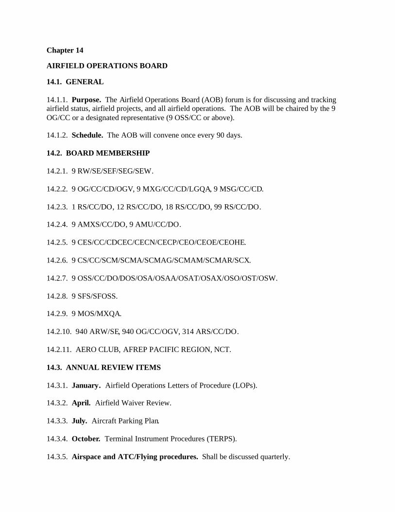
Chapter 14
AIRFIELD OPERATIONS BOARD
14.1. GENERAL 14.1.1. Purpose. The Airfield Operations Board (AOB) forum is for discussing and tracking airfield status, airfield projects, and all airfield operations. The AOB will be chaired by the 9
OG/CC or a designated representative (9 OSS/CC or above). 14.1.2. Schedule. The AOB will convene once every 90 days. 14.2. BOARD MEMBERSHIP 14.2.1. 9 RW/SE/SEF/SEG/SEW. 14.2.2. 9 OG/CC/CD/OGV, 9 MXG/CC/CD/LGQA, 9 MSG/CC/CD. 14.2.3. 1 RS/CC/DO, 12 RS/CC/DO, 18 RS/CC/DO, 99 RS/CC/DO. 14.2.4. 9 AMXS/CC/DO, 9 AMU/CC/DO. 14.2.5. 9 CES/CC/CDCEC/CECN/CECP/CEO/CEOE/CEOHE. 14.2.6. 9 CS/CC/SCM/SCMA/SCMAG/SCMAM/SCMAR/SCX. 14.2.7. 9 OSS/CC/DO/DOS/OSA/OSAA/OSAT/OSAX/OSO/OST/OSW. 14.2.8. 9 SFS/SFOSS. 14.2.9. 9 MOS/MXQA. 14.2.10. 940 ARW/SE, 940 OG/CC/OGV, 314 ARS/CC/DO. 14.2.11. AERO CLUB, AFREP PACIFIC REGION, NCT. 14.3. ANNUAL REVIEW ITEMS 14.3.1. January. Airfield Operations Letters of Procedure (LOPs). 14.3.2. April. Airfield Waiver Review. 14.3.3. July. Aircraft Parking Plan. 14.3.4. October. Terminal Instrument Procedures (TERPS). 14.3.5. Airspace and ATC/Flying procedures. Shall be discussed quarterly.

Chapter 15 PILOT/AIRFIELD OPERATIONS FLIGHT LIAISON PROGRAM 15.1. GENERAL 15.1. Purpose. The Pilot/AOF Liaison Program is intended to provide a forum for pilots and airfield operations flight personnel to exchange information and feedback, enhancing flight safety and improving ATC services in the local environment. 15.2. Membership. The target membership for the liaison program are individuals performing flying, ATC and AM Ops on a daily basis. The liaison program is not intended to involve squadron commanders or operations officers as members; however, the support from squadron leadership is instrumental to the success of the liaison program. 15.2. RESPONSIBILITIES 15.2.1. AOF/DO/SO. The AOF/CC will designate the AOF/DO/SO as the primary representative for the Airfield Operations Flight. The AOF/DO/SO will:
15.2.1.1. Manage and participate in the Pilot Liaison Program. When organizing and conducting a liaison visit to an agency or unit, bring the Pilot/AOF Liaison Program NCOIC, designated air traffic representative, and the primary or alternate AM Ops representative as required/available. 15.2.1.2. Create and distribute meeting minutes to the AOF/CC, Complex Chief Controller, appropriate ATC and AM Ops liaisons, and the agencies visited. 15.2.1.3. Identify problem areas and/or concerns surfaced in liaison meetings, staff corrective actions, and track them through completion. 15.2.1.4. Appoint a primary and alternate air traffic control liaison for each flying organization and a primary and alternate liaison from AM Ops.
15.2.2. Program NCOIC. A Pilot/AOF Liaison Program NCOIC shall be appointed by the AOF/DO/SO. The NCOIC is highly encouraged to attend all meetings with the flying organizations, and will assist the AOF/DO/SO to the maximum extent possible. 15.2.3. ATC/AM Ops Liaisons. Works under the direction of the AOF/DO/SO and the Program NCOIC and at a minimum will:
15.2.3.1. Visit or contact on-base units (940 ARW, 1 RS, 99 RS, and the Aero Club) quarterly or when deemed necessary. Visit off-base units, airports, and fixed base operators as required. In most cases, the AOF/DO or AOF/SO will coordinate and lead the visit.

15.2.3.2. Help facilitate understanding of pilot requirements and concerns, controller and flight dispatch services, AM Ops functions, and air traffic system functions and limitations.
15.2.3.3. Remind customers/pilots of the services available to them at BAFB, limitations of the local system, potential problem areas, mid-air collision threats, etc. 15.2.3.4. Solicit input/feedback from the agencies visited. 15.2.3.5. Deliver Mid-Air Collision Avoidance and Bird Aircraft Strike Hazard pamphlets, surveys, and other visual aids, as appropriate. 15.2.4. Pilot Liaisons. Flying squadrons/Aero Club will designate a primary and alternate representative to meet with their designated ATC/AM Ops liaisons quarterly or when deemed necessary. Pilot liaisons should continually gather inputs from the flying community and notify their ATC/Am Ops counterparts as needed if investigation is required prior to conducting a meeting. LAWRENCE L. WELLS, Colonel, USAF Commander, 9th Reconnaissance Wing

ATTACHMENT 1
AIRFIELD DIAGRAM
Airfield Diagram (NOT TO SCALE)
NORTH
A
B
L F
E D C
F
H K
G
C
TACAN
12,000’ X 300’
4,500’ 7,500’ 7,500’ 4,500’
1000’ X 300’ 2240’ X 300’
1 1A 2 2A 3 3A 4 5 6 7 8 9
17A 17 16A 16 15 14 13 12 11 10
Tanker Ramp
U-2 Ramp VIP 2
VIP 1 T-38 Ramp
I H G F E U T S R Q P O N M L K J
M
Wind Sock/Sensor 3 Wind Sock/Sensor 2 Wind Sock/Sensor 1
15 ILS Glideslope Antenna
J
I
GPN-22 (PAR)
HCP-1 HCP-2
F
33
15
Instrument hold lines
Runway hold lines
Helicopter landing pad
Wash Rack
2
3
4
5
6
1
7
33 ILS Glideslope Antenna
HCP-1 Hazardous Cargo Pad PAVE PAWS
BAB TACAN R-072 / 4.7nm
Controlled Bailout Area BAB TACAN R-057 / 3nm IN
S INS Checkpoint
INS
INS
Fence Line
Glideslope Critical Area
Precision Approach Critical Areas
GAT/R
Aero Club Ramp
Hot Brakes
Firing Range Approx 3nm West
Localizer Critical Area
Field Elevation 113 ft MSL
Runway gradient negligible (<0.1%)
Fire Station
Tower Visual Blind Spots
Tower
Arnold Ave.

TTACHMENT 2
RADIO CONTROLLED MOVEMENT AREAS
NORTH
A
B
L F
E D C
F H K
G
C
TACA
1 1A 2 2A 3 3A 4 5 6 7 8 9
17A 17 16A 16 15 14 13 12 11 10
Tanker Ramp
U-2 Ramp
VIP 2
VIP 1 T-38 Ramp
I H G F E U T S R Q P O N M L K J
Arnold Ave.
M J
I
F
33
15
Controlled Movement Areas (NOT TO SCALE)
Aircraft Movement Area
Vehicle Movement Area
Wash Rack
2
3
4
5
6
1
7
Aero Club Ramp
Tower
Fire Station
IFR Holdlin
e
VFR Holdline
VFR Holdline

ATTACHMENT 3
RECTANGULAR VFR TRAFFIC PATTERN
1100’ MSL
1100’ MSL
Approx. 2.5 Mi
Approx.
45 Sec
(No Wind)
1. Standard pattern will be flown east of the runway2. Do not overfly: Pave Paws, Base Housing, Main Base Area, Hospital, Trailer Park3. CAUTION: FOR PATTERN EXTENSIONS TO THE NORTHEAST OBSTACLE -- [1029’ BAB 347R/008.2 DME]
Approx. 2 Mi
Rectangular VFR Traffic Pattern
M-60
Range
EOD Range
N

ATTACHMENT 4
38/TRANSIENT JET OVERHEAD TRAFFIC PATTERN
33 152100 MSL 2100 MSL
Level Turn
Level Turn
Descending Turn
Descending Turn
T-38/Transient Jet Aircraft Overhead Traffic Pattern
Final Approach Minimum RolloutAlt. 350’ MSL. Not less than 3/4 milefrom end of runway.
Final Approach Minimum RolloutAlt. 350’ MSL. Not less than 3/4 mile
from end of runway.
Initial Approach 3-5 mi from end of runway
Initial Approach 3-5 mi from end of runway
Notes:1. Standard overhead traffic pattern will be flown west of the runway.2. East overhead traffic pattern authorized when approved or directed by tower.
N

ATTACHMENT 5
38/KC-135 LOW CLOSED TRAFFIC PATTERN
U-2/T-38/KC-135 Low Closed Traffic Maneuver
15 33
T-38/KC 135 680’ - 2100’ MSLU-2 540’ - 2100’ MSL Note:
1. Right Traffic RWY 152. Left Traffic RWY 333. Pattern will be flown west of the runway
N

ATTACHMENT 6
2/KC-135 OVERHEAD TRAFFIC PATTERN
33 15
3/4 mi3/4 mi
180 Descending Turn180 Descending Turn
180 Descending Turn180 Descending Turn
Rollout Approx. 1100’ MSL Rollout Approx. 1100’ MSL
3 NM 1600’ MSL Initial 1-3 NM 1600’ MSL
Final Approach 350’ MSL Wings Level Final Approach 350’ MSL
Wings LevelThreshold is end of runway
U-2/KC-135 Overhead Traffic PatternN

ATTACHMENT 7
2 CLOSED TRAFFIC
15 331100’ MSL1100’ MSL
Slow Descent Prior to Base Turn
U-2 Closed Traffic
Notes:1. Standard traffic will be flown east of the runway.2. West traffic authorized when approved or directed by tower.3. Minimum altitude for turnout is 400’ AGL.
N
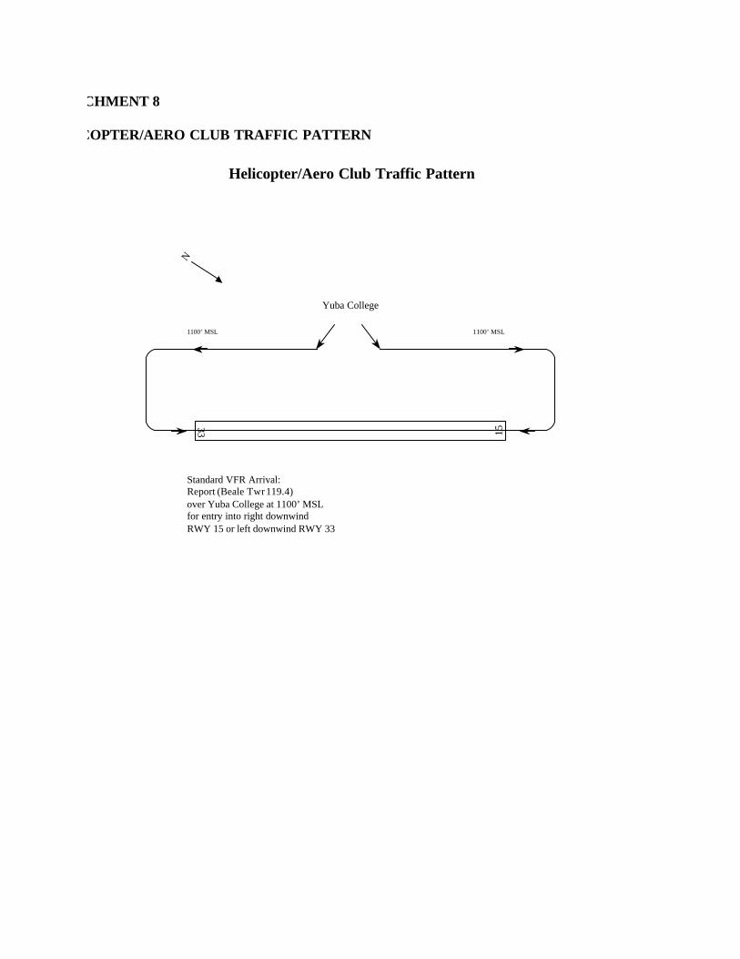
ATTACHMENT 8
HELICOPTER/AERO CLUB TRAFFIC PATTERN
33 15
Yuba College
1100’ MSL 1100’ MSL
Standard VFR Arrival:Report (Beale Twr 119.4)over Yuba College at 1100’ MSL for entry into right downwind RWY 15 or left downwind RWY 33
Helicopter/Aero Club Traffic PatternN

ATTACHMENT 9
38/TRANSIENT JET AIRCRAFT CLOSED TRAFFIC
15 33 2100’ MSL
T-38/Transient Jet Aircraft Closed Traffic
Notes:1. Standard traffic will be flown west of the runway2. East traffic authorized when approved or directed by tower.
N
2100’ MSL

ATTACHMENT 10
SIMULATED FLAMEOUT (SIDE-VIEW) PATTERN
Simulated Flameout Pattern
Side View
High Key: First two-thirds of runway Low Key: Abeam the area between the first 1/3 of the runway and 1/2 mile from the approach end
of the runway C – Base Key: Midpoint of turn from downwind to final
Overhead View
A
B
C
High Key First 2/3 of RWY
A
Low key position varies with wind direction/velocity
B
C

ATTACHMENT 11
2 SIMULATED FLAMEOUT PATTERN
15
BC
33
CDE
HIGH KEY
LOW KEY
LOW KEY
HIGH KEY
U-2 Aircraft Simulated Flameout Pattern
RWY 15HIGH KEY: Altitude is always 1,100 to 2,100 feet MSL and is locatedbetween the approach end and Taxiway ‘D’, depending on winds.
LOW KEY: Altitude is approx. 600 to1,100 feet MSL and normally abeam the area between the first 1/3 of the runway and1/2 mile from the approach end of the runway.
RWY 33HIGH KEY: Altitude is always 1,100 to 2,100 feet MSL and is locatedbetween the approach end and Taxiway ‘C’, depending on winds.
LOW KEY: Altitude is approx. 600 to1,100 feet MSL and normally abeam the area between the first 1/3 of the runway and1/2 mile from the approach end of the runway.
NOTE: West pattern authorized when approved or directed by tower.
N

ATTACHMENT 12
SIMULATED FLAMEOUT ALTERNATE ENTRY PROCEDURES
N
Rwy 15 Overhead SFO Groundtrack
Left Low Key 600 – 1,100 MSL
Right Low Key 600 – 1,100 MSL
Flame BAB 020-050 4 DME
Claw BAB 060-090 4 DME
Tooth BAB 340-010 4 DME
BAB 220-260 DME
Rwy 33 Overhead SFO Groundtrack
Flame BAB 020-050 4 DME
Claw BAB 060-090 4 DME
Tooth BAB 340-010 4 DME
BAB 220-260 4 DME
Runway 15 Entry point altitude is 1,100 – 4,000 MSL
Runway 33 Entry point altitude is 1,100 – 4,000 MSL
Left Low Key 600 – 1,100 MSL
Right Low Key 600 – 1,100 MSL
Make your request with tower “CALL SIGN, REQUEST (Entry Point), at (Altitude).” Remain at or below 2,100 MSL and within 5 DME until cleared otherwise. When inbound report “CALL SIGN, (Entry Point), inbound for LOW KEY.” Proceed direct to LOW KEY. Request deviations with Tower. Do not cross runway centerline unless cleared by Tower.
Yuba College
Yuba College
Hill
Ranch
Pave Paws 2100
Clinic
Clinic
Pave Paws 2100
Hill
Ranch

ATTACHMENT 13
CLASS C AIRSPACE
10 NM
5 NM
41----16
127
007
41----26
41----SFC
Class C Airspace
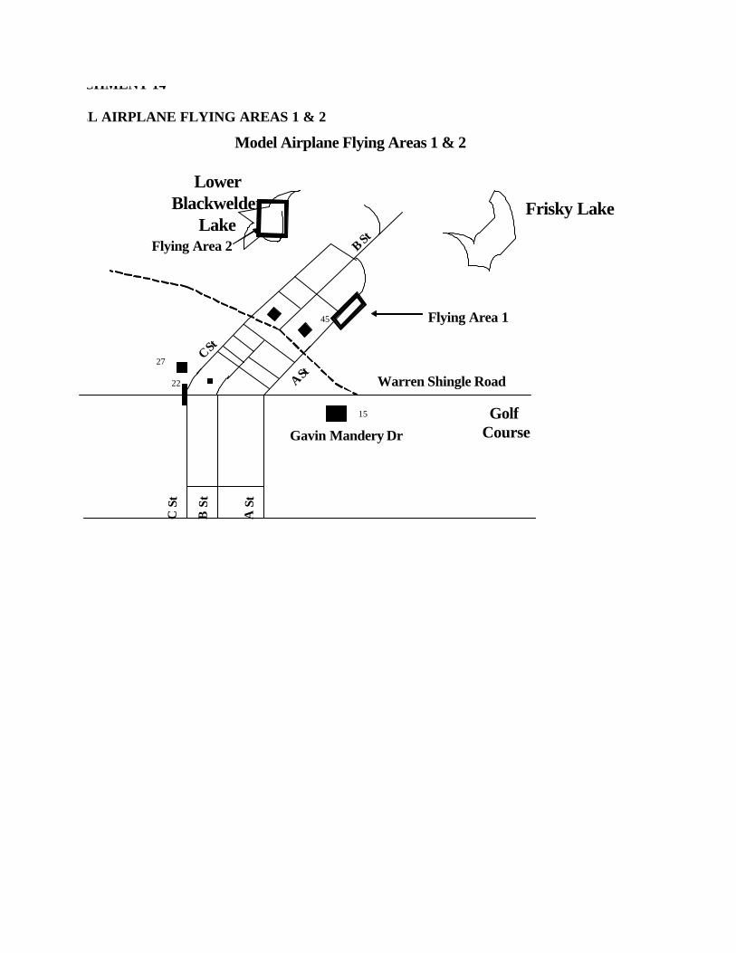
ATTACHMENT 14
MODEL AIRPLANE FLYING AREAS 1 & 2
Flying Area 1
B St
15
Model Airplane Flying Areas 1 & 2
45
Warren Shingle Road
C St
A St27
22
Golf CourseGavin Mandery Dr
A S
t
C S
t
B S
tFrisky Lake
LowerBlackwelder
LakeFlying Area 2

ATTACHMENT 15
MODEL AIRPLANE FLYING AREA 3
Flying Area 3
Model Airplane Flying Area 3
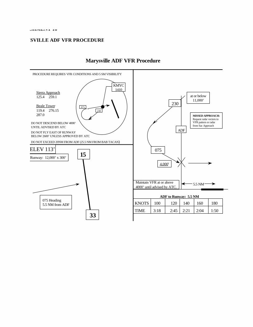
ATTACHMENT 16
MARYSVILLE ADF VFR PROCEDURE
PROCEDURE REQUIRES VFR CONDITIONS AND 5 SM VISIBILITY
Sierra Approach125.4 259.1
Beale Tower119.4 276.15287.0
Marysville ADF VFR Procedure
230075
KMYC1410
230
Maintain VFR at or above4000’ until advised by ATC.
ADF to Runway: 5.5 NM
TIME 3:18 2:45 2:21 2:04 1:50
15
33
ELEV 113’Runway: 12,000’ x 300’
075 Heading5.5 NM from ADF
at or below 11,000’
4,000’
DO NOT EXCEED 20NM FROM ADF (25.5 NM FROM BAB TACAN)
KNOTS 100 120 140 160 180
075
ADF
5.5 NM
DO NOT DESCEND BELOW 4000’UNTIL ADVISED BY ATC
MISSED APPROACH:Request radar vectors to VFR pattern or radar from Sac Approach
DO NOT FLY EAST OF RUNWAY BELOW 2600’ UNLESS APPROVED BY ATC

ATTACHMENT 17
LINE DOCK OPERATIONS
HANGAR126
HANGAR125
Blast ShieldBlast Shield Blast Shield Blast Shield Blast Shield
Fence FenceTA
XIW
AY
“H”
Hi-Line Dock Operations
The area encompasses the leftside of the hangers to the blacktop next to the blast shields.
HANGAR124
HANGAR123
HANGAR122
175 ft

ATTACHMENT 18
FLIGHT LINE ENTRY POINT – TAXIWAY A
FLIGHT LINE ENTRY POINTS (FEP) AT TAXIWAY A
FEP
FEP
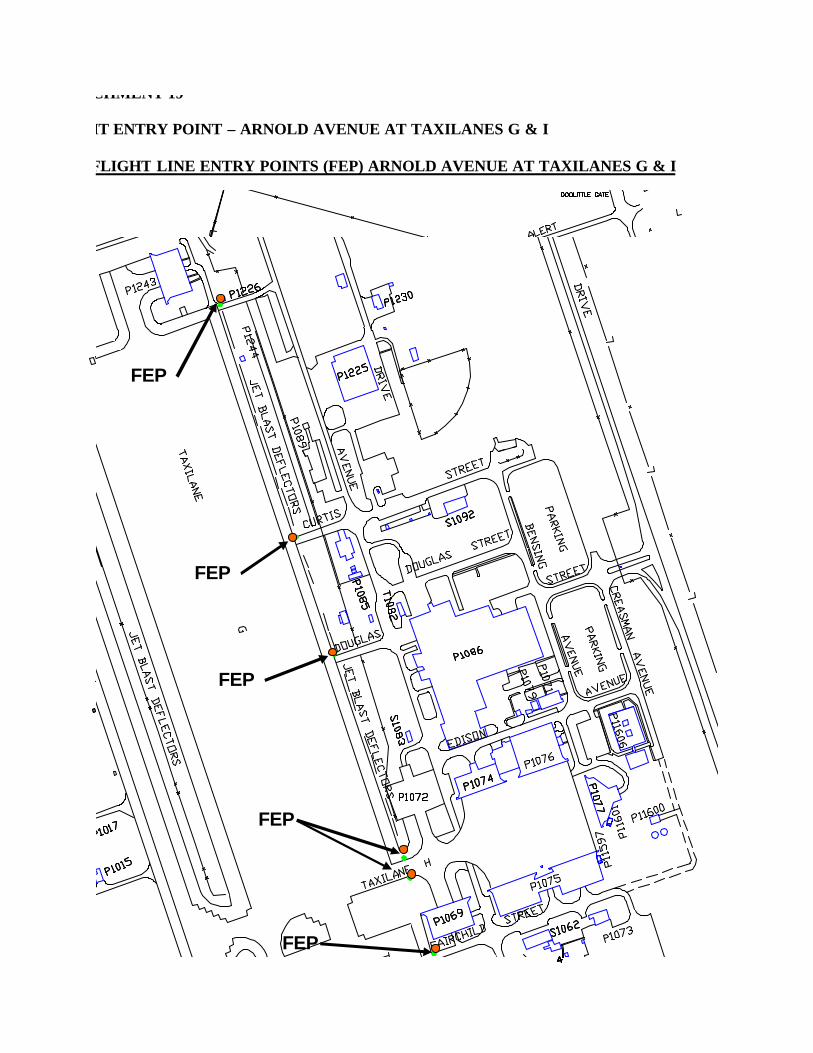
ATTACHMENT 19
FLIGHT ENTRY POINT – ARNOLD AVENUE AT TAXILANES G & I
FLIGHT LINE ENTRY POINTS (FEP) ARNOLD AVENUE AT TAXILANES G & I
FEP
FEP
FLIGHTLINE ENTRY POINTS (FEP) AT TAXIWAY A
FEP
FEP
FEP
FEP
FEP
FEP
FEP
FEP
FEP
FEP

ATTACHMENT 19 CONTINUED
FLIGHT LINE ENTRY POINTS (FEP) ARNOLD AVE SOUTH -- TAXILANE I CONTINUED
FEP
FEP

ATTACHMENT 20
RESTRICTED AREA ENTRY CONTOL POINTS (ECP) TAXILANE G & H
RESTRICTED AREA ENTRY CONTROL POINTS (ECP) TAXILANE G & H
ECP

ATTACHMENT 21
RESTRICTED AREA ENTRY CONTROL POINTS (ECP) SOUTH TAXILANE I
RESTRICTED AREA ENTRY CONTROL POINTS (ECP) SOUTH TAXILANE I
ECP

ATTACHMENT 22
VFR REPORTING POINTS
HWY 65
HWY 70
HWY 20
YUBA R
4100 2600
4100 SFC
4100 1600
5
10 NM
1.
2.
4.
6.
1. Yuba River - East to West 2. Wheatland Gate - 3.8 NM South 3. Yuba County Airport - 7 NM West, South West 4. Yuba College - 5 NM West 5. Hammonton Airstrip - 3 NM North 6. Tank Farm - 2.2 nm South
R-007
R-127